

Page 1
Clean air solutions built for you.
MORE INFORMATION AVAILABLE AT WWW.ENVIRCO.COM
Industrial
Cleanroom Products
®
Original
» MAC 10
®
IQ™
» MAC 10
®
LEAC™
» MAC 10
®
LEDC™
» MAC 10
» Ducted Ceiling Module:
DCM & RSR
» AC or DC Control Systems
Envirco MAC 10 and VE5 are registered trademarks of Envirco, USA. Specications subject to modications or changes without notice.
US patents 4,560,395 and 5,470,363.
Other patents issued and pending in foreign countries. Special thanks to Connect2Cleanrooms for cleanroom photography.
Copyright ©2013 Envirco. All Rights Reserved.
Form P/N#: 267381-001 0913
Hospital & Healthcare
Hospital & Healthcare
®
and IsoClean
» IsoClean
with Ultraviolet Light
®
» AirCeil
» Hospi-Gard® Room
Pressure Monitor
Enviramedic Products
» HOR Horizontal Flow
Enclosure
» HCF Horizontal Flow
Surgery Room
» VOR Vertical Flow Surgery
Isolator
The Cavendish Centre, Winnall Close | Winchester, Hampshire; S023 OLB, UK
Pharmaceutical
Pharmaceutical &
Medical Device
®
RX products
» MAC 10
are available in stainless
steel diffuser screens or
complete stainless steel
construction
» Unimodule M-2 Vertical
Unidirectional Flow
Workstation
» METD 100% Exhausted
Vertical Flow Workstation
» Unidirectional Downow
Module
tel: 919.775.2201 | toll free: 800.884.0002 | fax:800.458.2379
tel:+44(0)1962.840465 | fax:+44(0)1962.828619
www.envirco-emea.com | email: r[email protected]
Building #1, 200 Middle Suhong Road | Suzhou, Jiangsu PRC 215021
tel: +86.512.62587180 | fax: +86.512.62580031
Laboratory & Research
Laboratory & Research
» 100-Plus Horizontal or
Vertical Flow Clean Bench
» Unidirectional Flow
Horizontal Flow Bench (LF)
» TT Table Top Horizontal
Flow Clean Bench
» EnviraLab Sterility Module:
ESM
» NSF 49 Listed Biological
Safety Cabinet
101 McNeill Road | Sanford, NC 27330, USA
www.envirco.com | email: [email protected]
Envirco European Sales
Envirco Asian Sales and Manufacturing
www.envirco.com | email: [email protected]
Envirco USA
MAC 10® VCU Controls
Fan Filter Unit
Standard, RSR, & RSRE Models
OPERATION GUIDE
Page 2
MAC 10® VCU Control
Operation Guide
MAC 10 LEDC and IQ VCU controls
for remote mount part number 11166-001
Wiring Details & Operation
■ Wiring Detail
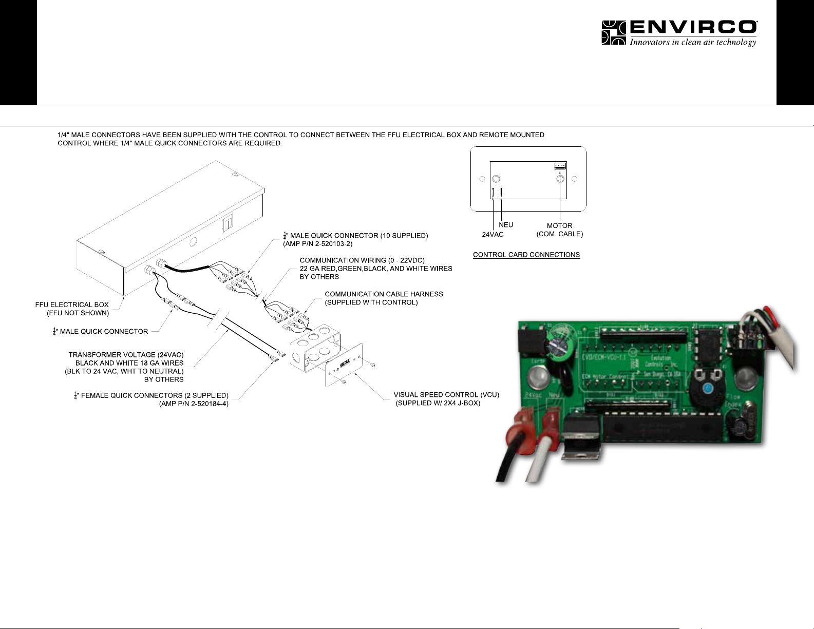
Please make sure all power is off before making these connections.
• The six leads exiting the FFU electrical box have ¼” female quick connectors.
• The leads attached to the control have ¼” female quick connectors.
• Please follow all applicable local codes for low voltage wiring. Conduit or plenum
rated cables may be required.
• The wiring between the FFU electrical box and the controls require the 18 gauge
black and white leads (24VAC) be connected to the same 18 gauge wire colors on
the control (white to white and black to black).
• The 22 gauge communication wiring (0-22VDC) is also color coded. Connect the
red wire out of the electrical box to the red wire on the remote mounted control.
Connect the green wire to the green wire; the black wire to the black wire and the
white wire to the white wire.
• 1/4” male connectors have been supplied with the control to connect between the
FFU electrical box and remote mounted control where 1/4” male quick connectors
are required.
■ VCU Operation
The fan lter unit needs to be turned on prior to operation of the control. With the
Visual Speed Control board, a single screw driver is required to adjust the unit airow.
Just to the left of the LED readout is a recessed blue slotted stem which when turned
clockwise will increase the airow and if turned counter clockwise will decrease the
airow. The LED readout alternates between outputting the selected ow index (%)
and the actual motor RPM.
 Loading...