

Page 1
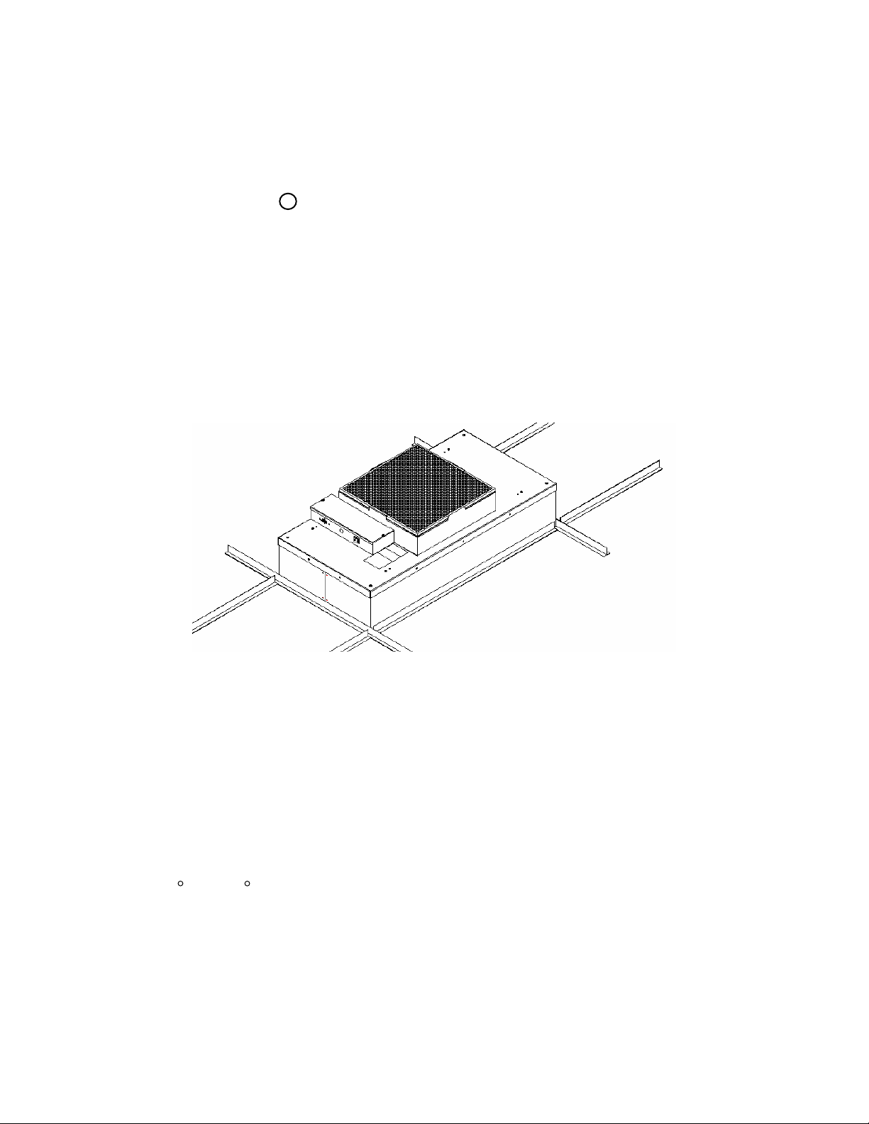
*** READ AND SAVE THESE INSTRUCTIONS ***
MAC 10 LE-AC FAN FILTER MODULE
R
INSTALLATION AND SERVICE MANUAL
STANDARD, RSR, RSRE MODELS
Mac 10 and VE5 are registered Trademarks of the
Envirco, U.S.A.
US Patents 4,560,395 and 5,470,363 Other patents issued and pending in foreign countries
R
R
Version 1
Updated 2.5.11
Page 2

Critical operation conditions of the MAC 10
11194-XXX Mac 10 L E AC 2x4 (600x1210mm) Standard Filter
1. Touching of the HEPA filter will damage it, voiding the warranty on the
filter. The screen is only to protect against an accidental ‘touch’ of the
filter. Never place a hand or tool on the filter. Never lie filter face flat
down on a surface always have filter on its side or back to protect from
damage.
2. Prior to powering the unit, verify that the unit has been plugged into the
correct voltage. The serial number label on the top of the Mac 10 unit has
the required voltage.
3. For reorder prepossess the Mac 10 part number and serial number
should be recorded. This information is located on the serial number
label, located adjacent to the electrical box. If you can’t located the Sales
Order Number please contact Envirco for this information.
Part Numbers Covered by this Manual
Mac 10 LE AC 2x4 (600x1210mm) RSR/E Filter
Note: A ‘Z’ in the part number indicates that the unit is special. This may
indicate a size change from standard or a special filter. Please contact
the factory for part numbers if this is the situation.
CAUTION
TO REDUCE THE RISK OF INJURY TO PERSONS, INSTALL FAN AT
LEAST 2.1M (7 FEET) ABOVE THE FLOOR
MAC 10 LE-AC SERVICE MANUAL
Page 3

READ AND SAVE THESE INSTRUCTIONS
WARNING!
TO REDUCE THE RISK OF FIRE, ELECTRICAL SHOCK, OR INJURY TO PERSONS,
OBSERVE THE FOLLOWING :
A. Installation work and electrical wiring must be done by qualified person(s) in
accordance with all applicable codes and standards, including fire-rated construction.
B. When cutting or drilling into wall or ceiling, do not damage electrical wiring and other
hidden utilities.
C. If this unit is to be installed over a tub or shower, it must be marked as appropriate
for the application.
D. Use this unit only in the manner intended by the manufacturer. If you have any
questions, contact the manufacturer:
ENVIRCO
101 McNeill Road
Sanford, NC 27330
Tel: (919) 775-2201
Tel: (800) 884-0002
Fax: (800) 458-2379
Email: [email protected]
ASIAN SALES
Building #1
200 Middle Suhong Road
Suzhou, Jiangsu
PRC 215021
Tel: (86) 512 6258 0031
Fax:(86) 512 6258 7180
Europe, Middle East & Africa (EMEA)
TRION Div of Ruskin Air Management Ltd
European Operations
The Cavendish Center Winnall Close
Winchester Hampshire
S023 OLB, UK
Tel: +44 (0) 1962 840465
Fax: +44 (0) 1962 828619
E. Before servicing or cleaning unit, switch power off at service panel and lock service
panel to prevent power from being switched on accidentally.
MAC 10 LE-AC SERVICE MANUAL
2 EGAP
Page 4

Table of Contents
Title Page
1 INSTALLATION ................................................................................................................................. 4
FIGURE 1 – UNIT UNCRATING.............................................................................................................. 4
2 SERVICE: CLEANING THE MAC 10 LE-AC PREFILTER (FOAM)....................................... 5
FIGURE 2 – FOAM PREFILTER CLEANING ....................................................................................... 5
3 SERVICE: CLEANING THE MAC 10 LE-AC PREFILTER (G4 PLEATED PREFILTER) .. 6
FIGURE 3 – G4 PREFILTER REPLACEMENT.................................................................................... . 6
4 SERVICE: REMOVAL AND REPLACEMENT OF THE HEPA/ULPA FILTER
(STANDARD UNIT) .................................................................................................................................... 7
FIGURE 4 – STANDARD FILTER REPLACEMENT ........................................................................... 7
5 SERVICE: REMOVAL AND INSTALLATION OF THE ROOM SIDE REPLACEABLE
GEL SEAL FILTER (RSR/RSRE).............................................................................................................
FIGURE 5 – RSR SHEET METAL FILTER REPLACEMENT............................................................ 9
8
6 SERVICE: REMOVAL AND INSTALLATION OF THE MOTOR (STANDARD AND RSR
MODELS) ................................................................................................................................................... 10
FIGURE 6 – MOTOR REPLACEMENT ............................................................................................... . 11
7 SERVICE: REMOVAL AND INSTALLATION OF THE RSRE MOTOR.............................. 12
FIGURE 7 – RSRE MOTOR REPLACEMENT .................................................................................... 13
FIGURE 8 –MOTOR BLOWER COMPONENTS ................................................................................ 13
8 ON/OFF SWITCH - SPEED/AIRFLOW ADJUSTMENT ............................................................ 14
FIGURE 9 – ELECTRICAL BOX FACE............................................................................................... . 14
9 TROUBLE SHOOTING: ............................................................................................................. ..... 15
10 MAC 10 LE-AC WIRING DIAGRAMS .........
11 MAC 10 LE-AC REPLACEMENT PARTS LIST: ....................................................................
12 WARRANTY .................................................................................................................................. 18
............................................................................. 16
17
MAC 10 LE-AC SERVICE MANUAL
Page 5
1 INSTALLATION
Note: The MAC 10 LE-AC Fan Filter Unit is completely assembled at the factory with
the exception of the optional ¼” (0.64 cm)-20 eyebolts, which can be used
when hanging the unit from an overhead structure.
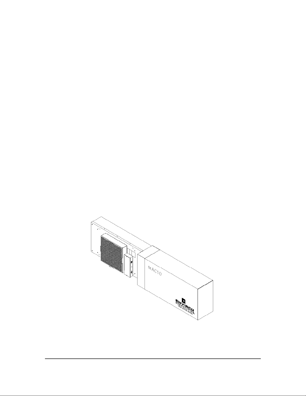
Step 1. Carefully remove the unit from the shipping carton and inspect for any damage
that may have occurred during transportation. (See Figure 1)
Step 2. Wipe down plastic bag and move unit into clean room. (Double bagging is
available upon request.)
Step 3. If using rigidly supported grid (usually 2” (50 mm) or wider), raise unit through
ceiling and lower onto the gasketed grid. If using a flexible grid (typically
supported with wires) the unit must be secured to an overhead structure with
eyebolts, s-hooks and chain or ¼-20 all thread. A roll of high-density gasket has
been provided
for use with ungasketed grids. Note: special size units are
available to fit specific clean room grid systems.
Step 4. Have an electrician wire the unit to the appropriate voltage (115V, 220V, 277
AC), according to the wiring diagram in section IX and local electric codes. If
optional power cord was purchased, plug unit into a grounded recepta
cle. The
optional power cord is not acceptable for plenum installations.
V
Figure 1 – Unit Uncrating
MAC 10 LE-AC SERVICE MANUAL
4 EGAP
Page 6
2 SERVICE: Cleaning the MAC 10 LE-AC Prefilter (foam)
WARNING!
Disconnect the unit from the electrical power source before attempting any
service.
Tools Required: None
Note: To keep the filter in top operating condition, washing the foam prefilter is
recommended every three to six months.
Step 1. To gain access to the prefilter, remove the ceiling panel next to the unit, if
applicable.
Step 2. Switch the ON-OFF switch to the off position.
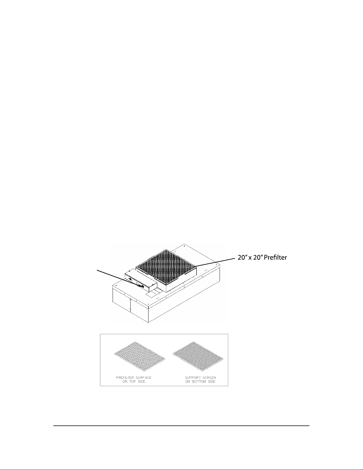
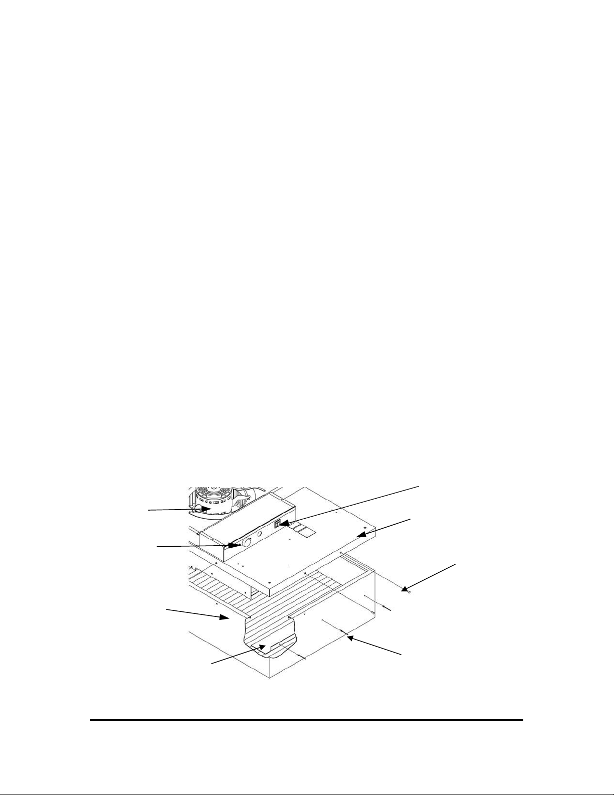
Step 3. Remove the prefilter from the snap-in frame. (See Figure 2)
Step 4. Clean the prefilter by hand washing in water with a mild detergent or by using a
vacuum cleaner. Allow prefilter to dry completely before replacing.
Step 5. Reassemble by reversing the above steps.
ON/OFF Switch
MAC 10 LE-AC SERVICE MANUAL
5 E G A P
Page 7
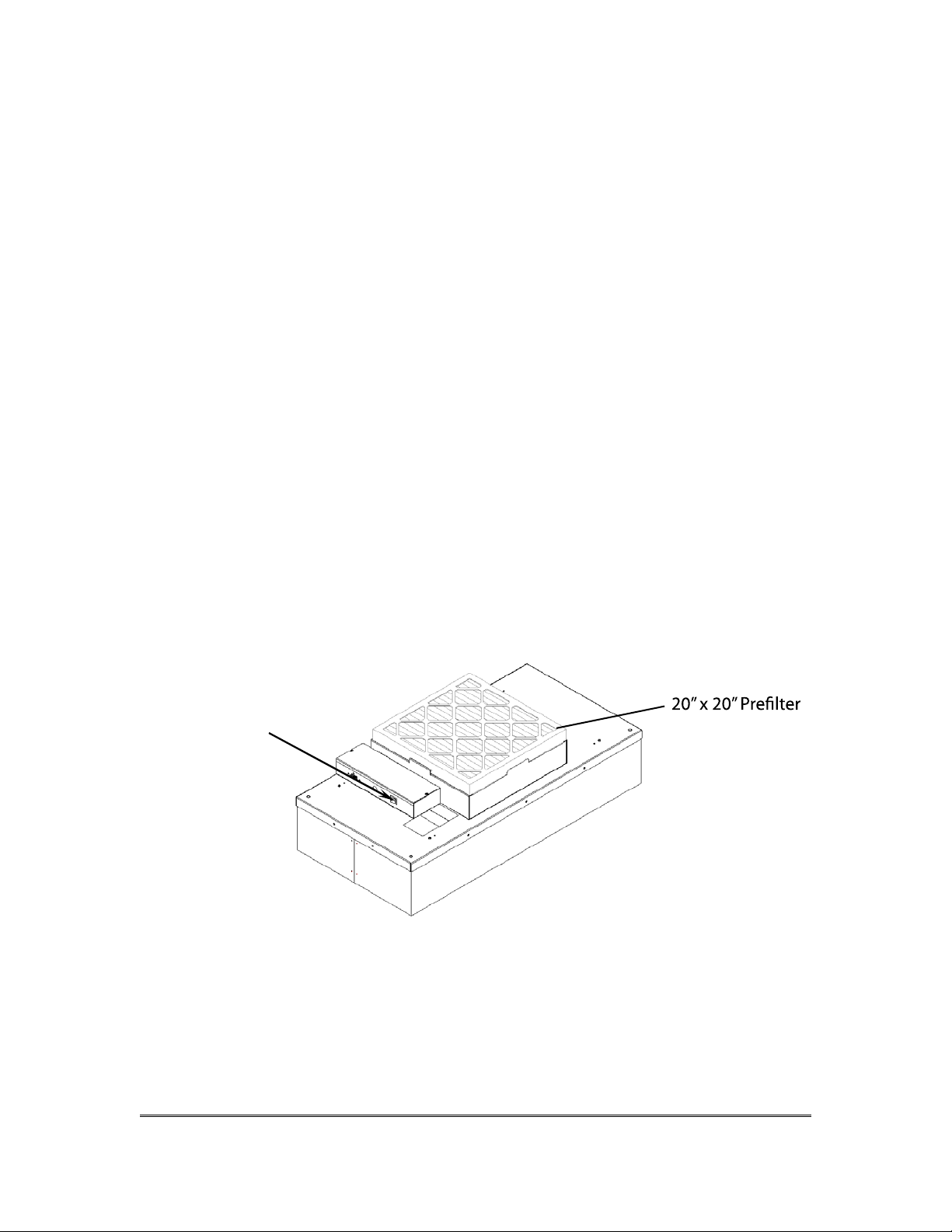
Figure 2 – Foam Prefilter Cleaning
3 SERVICE: Cleaning the MAC 10 LE-AC Prefilter (G4 Pleated
Prefilter)
WARNING!
Disconnect the unit from the electrical power source before attempting any
service.
Tools Required: None
Note: To keep the filter in top operating condition replacing the pleated prefilter is
recommended every twelve months or sooner.
Step 1. To gain access to the prefilter, remove the ceiling panel next to the unit, if
applicable.
Step 2. Switch the ON-OFF switch to the off position.
Step 3. Remove the prefilter from the snap-in frame. The beverage frame has slots
that have to be depressed to release the filter from the prefilter housing (See
Figure 3)
Step 4. After removing the new G4 pleated prefilter from the box, remove the die cut
slots from the beverage board frame and install on prefilter bracket.
Step 5. Reassemble by reversing the above steps.
ON/OFF Switch
Figure 3 – G4 Prefilter Replacement
MAC 10 LE-AC SERVICE MANUAL
6 E G A P
Page 8
4 SERVICE: Removal and Replacement of the HEPA/ULPA
)
)
Filter (Standard Unit)
WARNING!
Disconnect the unit from the electrical power source before attempting any
service.
WARNING!
The Standard Filter is protected with an expanded metal face screen. This is
never to be used to handle the filter. It is only for protection against an accidental
touch of the filter. Only handle the filter by the frame.
Tools Required: Phillips Head Driver, Battery Operated Drill with a 5/32 Drill
Bit, Rivet Hand Tool, Ø5/32 aluminum rivet grip range .126.187
Step 1. Remove unit from ceiling.
Step 2. Remove the 10 screws holding the HEPA/ULPA filter to the lid assembly.
Step 3. Lift the lid assembly off the HEPA/ULPA filter (see Figure 3). Remove Filter
deflectors using 5/32 drill bit. Keep filter deflectors to install in new filter.
Discard
Carefully install the filter deflectors into the new filter using the 5/32 rivets. Do
not touch or place the filter deflectors on the HEPA/ULPA media pack. This
could cause tears in the filter pack.
Note: Before replacing with a new HEPA/ULPA filter, carefully inspect the new filter for
any visible damage. Also inspect the gasket in the “tee” bar to insure a tight seal.
Replace as necessary.
the used filter as per requirements of the applicable regulations.
Step 4. Replace with the new HEPA/ULPA filter and assemble by reversing the above
steps.
ON/OFF
Lid Screw (10)
Lid Assembly
Speed Control
#8 SCREWS (10X
HEPA/ULPA
Filter
FILTER DEFLECTOR
Ø5/32 RIVET (6X
Figure 4 – Standard Filter Replacement
MAC 10 LE-AC SERVICE MANUAL
7 EGAP
Page 9

5 SERVICE: Removal and Installation of the Room Side
Replaceable Gel Seal Filter (RSR/RSRE)
WARNING!
Disconnect the unit from the electrical power source before attempting any
service.
WARNING!
The RSR Filter is protected with an expanded metal face screen. This is never to
be used to handle the filter. It is only for protection against an accidental touch of
the filter. Only handle the filter by the frame.
Tools Required: Phillips Head Driver
3/16” hex head wrench
Manpower Required: 2
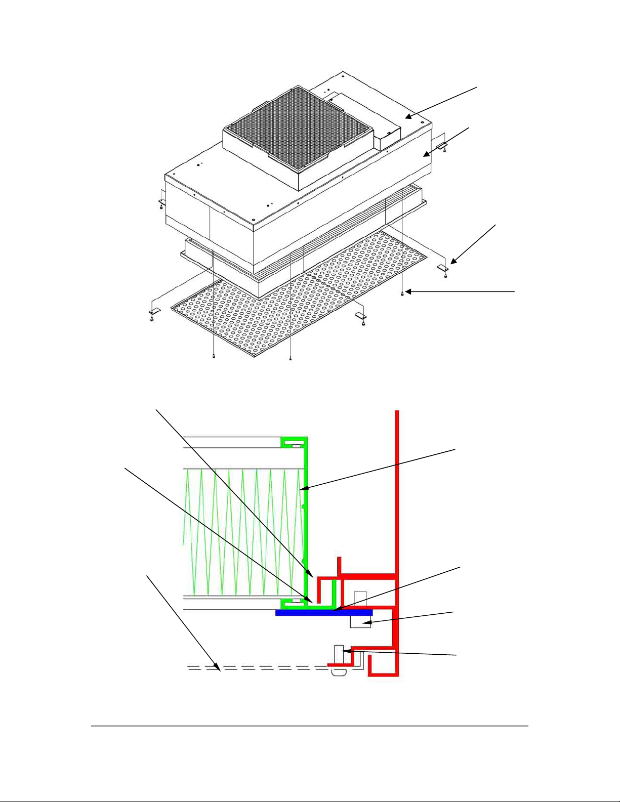
Step 1. Remove the diffuser screen by removing the 6 each 10-32x1/2 screws.
Step 2. Loosen the six 1/4x20 socket head screws far enough to rotate the filter clip
°. The filter will not drop during this operation. Slowly pull the filter away
90
from the knife-edge seal, taking care not to touch the filter face during this
operation. It is important to pull the filter slowly away from the seal, so that the
gel remains in the filter gel track.
Step 3. Inspect filter for visible damage, if damaged set aside for replacement or repair.
Step 4. Inspect the gel seal, if reinstalling the removed filter. Determine if the gel has
lost its ability to seal, if so repair the
Step 5. Place the filter against the filter-sealing surface of the RSR unit. Install filter
clips and screws. The clips can be rotated and angled into place. Using the
clips as a lever the filter can be seated. It is recommended to work either
clockwise or counter clock wise around the filter, raise the filter into the gel.
Step 6. Reinstall screen.
gel.
(Referenced by Figure 5 on page 9)
MAC 10 LE-AC SERVICE MANUAL
8
Page 10
Fan Filter Unit
2-Piece Welded
Plenum Housing
Filter Clip and
Screw (typ 6)
Diffuser Screen
Screws (typ 6)
Knife-edge
Seal
Gel
Track
Perforated
Screen
Filter
Filter
Clip
¼ -20
Cap
Screw
10-32 PHP
Screws
Figure 5 – RSR Sheet Metal Filter Replacement
MAC 10 LE-AC SERVICE MANUAL
9 EGAP
Page 11

6 SERVICE: Removal and Installation of the Motor (Standard
and RSR models)
WARNING!
Disconnect the unit from the electrical power source before attempting any
service.
WARNING!
Electrical service should be performed by licensed electricians or authorized
ENVIRCO service technicians.
Tools Required: Phillips Head Driver
3/8” (10mm) Hex Head Wrench
Pliers
5/32”(0.40 cm) Allen wrench
Step 1. To gain access to the motor, remove the ceiling panel next to the unit, if
applicable.
Step 2. Switch the ON-OFF switch to the off position.
Step 3. Remove the prefilter off the prefilter frame. (See Section II)
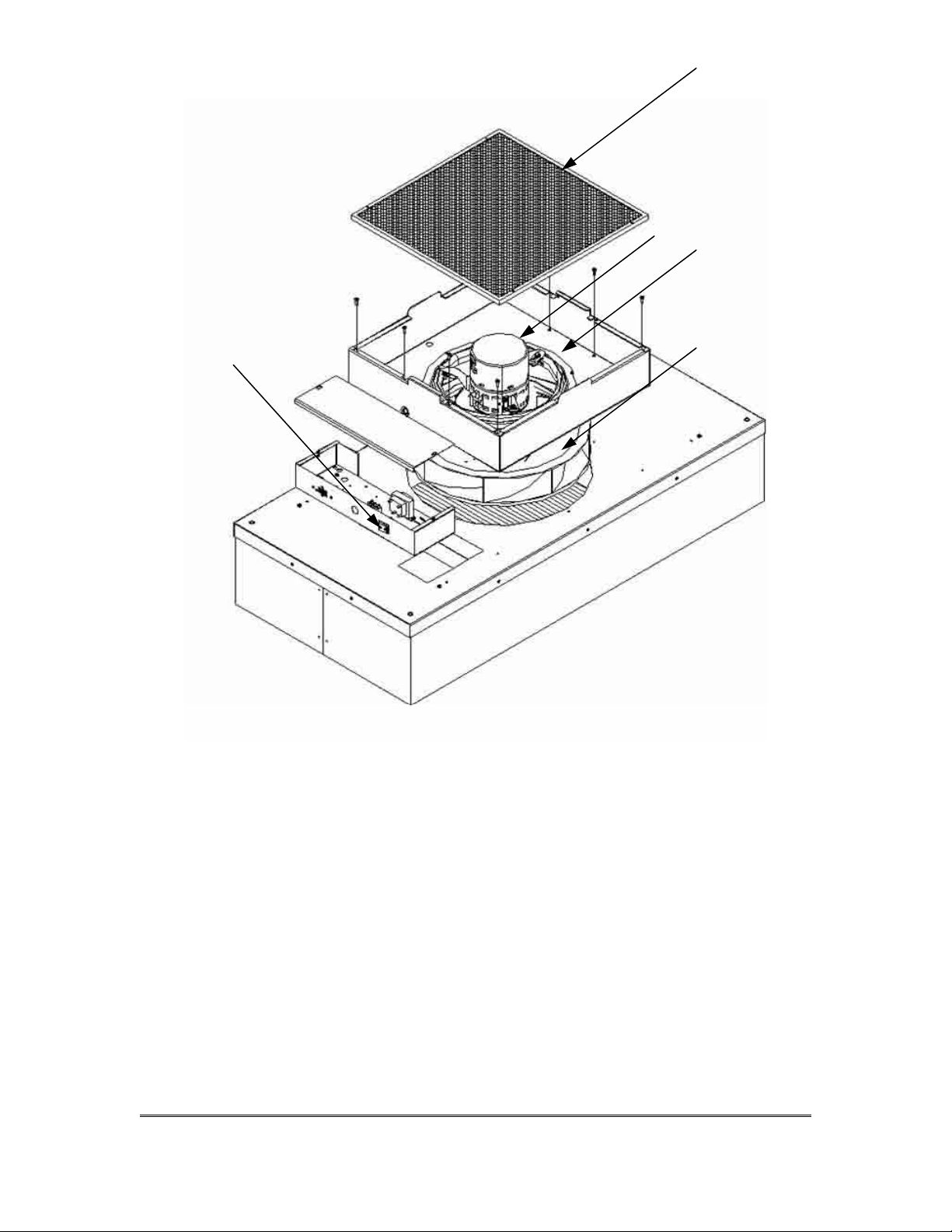
Step 4. Loosen the electrical box cover screws (2), and slide/lift off cover. (Figure 6)
Step 5. Make note of all wire locations for reinstallation later.
Step 6. Disconnect 5-pin and 16-pin wire harnesses from the electrical box housing.
Step 7. Remove the eight screws to free the motor/blower assembly from the lid
assembly. If using power drivers, set the unit to a low torque setting to avoid
stripping the sheet metal screw
Step 8. Using an adjustable wrench loosen the two set screws
wheel to the motor shaft.
Step 9. Mark the location of the motor support bracket (belly band), then loosen the bolt
just enough to allow the motor support bracket to slid off the motor.
Step 10. Using the removed motor, mark the new motor with the location of the motor
support bracket.
Step 11. Replace with the new motor and reassemble by reversing the above steps 1-8.
Set the spacing at 0.25” (6.35 mm) clearance between the blower and the
upper motor plate/prefilter frame. This will give a 0.11” overlap between the
venturi ring and the blower
s. (See Figure 6)
that attach the blower
(Referenced by Figure 6 on page 11)
MAC 10 LE-AC SERVICE MANUAL
9
Page 12
ON/OFF Switch
Prefilter
Motor
Venturi Ring
Blower Wheel
Figure 6 – Motor Replacement
MAC 10 LE-AC SERVICE MANUAL
11 EGAP
Page 13

7 SERVICE: Removal and Installation of the RSRE Motor
WARNING!
Disconnect the unit from the electrical power source before attempting any
service.
WARNING!
Electrical service should be performed by licensed electricians or authorized
ENVIRCO service technicians.
Step 1. To gain access to the motor, remove the gel seal filter (see Section III).
Step 2. Prior to removing motor/blower assembly, remove blower wheel to expose
motor connectors on motor. Using an adjustable wrench loosen the two set
screws that attach the blower wheel to the motor shaft. Disconnect the five and
sixteen pin connectors from the motor.
Step 3. While supporting the motor blower assembly from below, remove the six screws
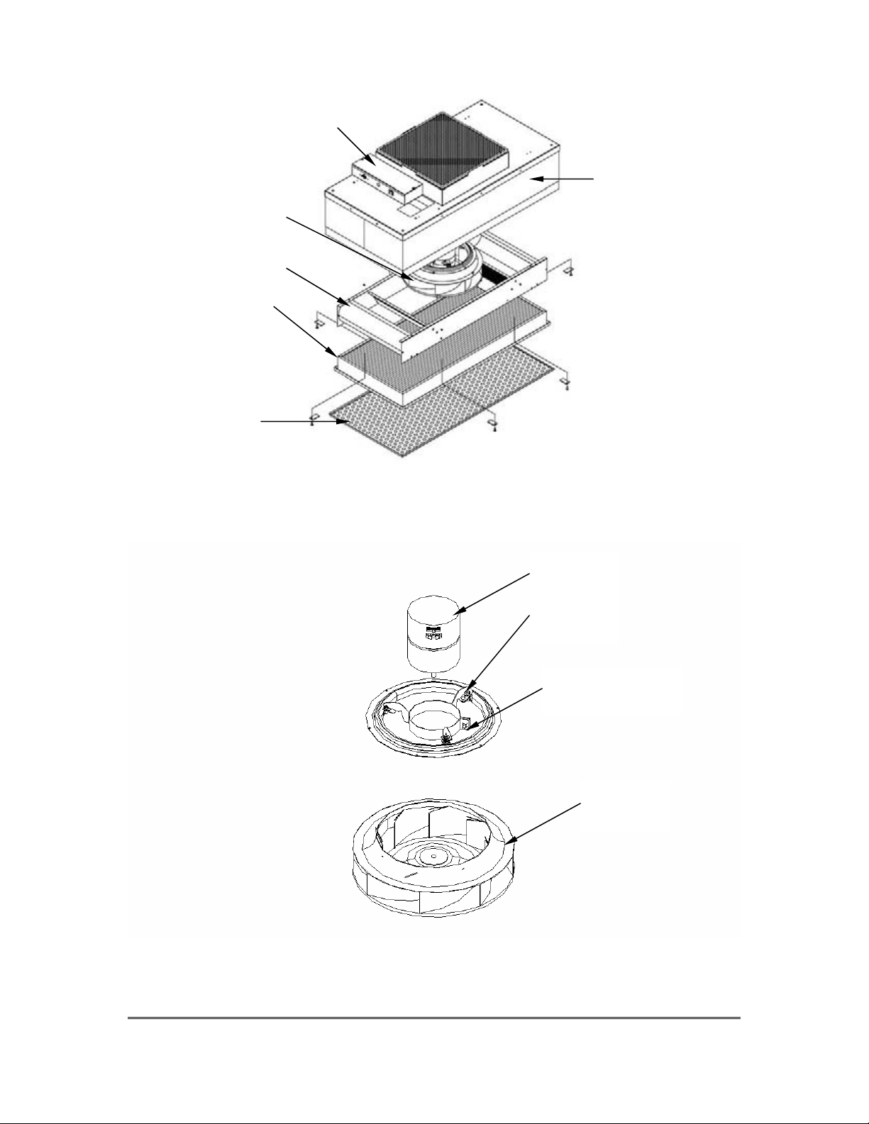
on the underside of the venturi ring and lower the assembly. (See Figure 7).
Note the baffle does not have to be removed to remove the motor/blower
assembly.
Step 4. Before removal of the motor mount bracket, measure the precise location of the
bracket on the motor. Remove the bracket.
Step 5. Replace with the new motor and reassemble by reversing the above steps. Set
the location of the motor mount bracket as
the spacing at 0.25” (6.35 mm) clearance between the blower and the upper
motor plate/prefilter frame creating a 0.11” (2.80 mm) overlap between the
wheel and the venturi ring. When reinstalling the assembly, align the plate to
insure that the leads will reach the electrical box.
measured (see above Step 6). Set
(Referenced by Figures 7 & 8 on page 13)
MAC 10 LE-AC SERVICE MANUAL
12
Page 14
Electrical connectors
Assy
located in inner
prefilter wall
Motor/Blower
Baffle Assembly
Gel Seal Filter
Screen
Plenum
Figure 7 – RSRE Motor Replacement
Motor
Venturi
Ring
Loosen Bolt to
remove Motor
Figure 8 –Motor Blower Components
Blower
Wheel
MAC 10 LE-AC SERVICE MANUAL
31 EGAP
Page 15
8 ON/OFF Switch - Speed/Airflow Adjustment
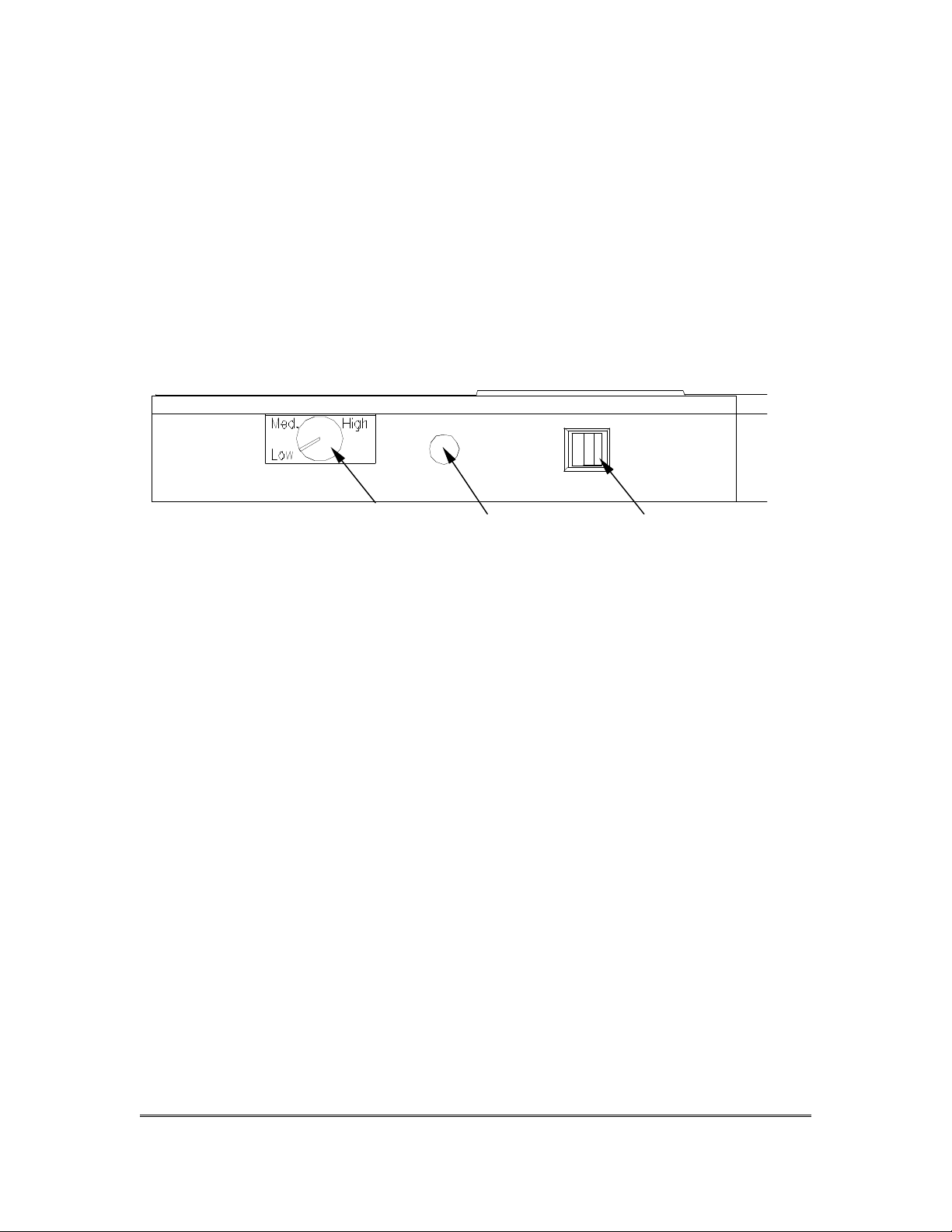
All MAC 10 units are equipped with a three-position rotary switch, which is located on
the side of the electrical box. (See Figure 8)
Recommended fan speed during initial start-up and operation is the “LOW” speed. As
airflow eventually decreases due to filter loading, fan speed may be increased by
moving the rocker switch to the top or “MEDIUM” position, and finally to the “HIGH”
position. Periodic airflow velocity readings(Per I.E.S.T. Specifications)
conducted to determine the filter condition and appropriate fan speed setting.
Figure 8 – 3 Speed Switch Adjustment
should be
ON/OFF SwitchElectrical Entrance3-Speed Switch
MAC 10 LE-AC SERVICE MANUAL
41 EGAP
Page 16

9 Trouble Shooting:
Unit is not adjustable
Step 1. Verify that rotation of the knob on the visual speed control does not change the
RPM or Flow Index display on the unit. If rotating does nothing, remove the electrical
box cover and remove the 4-pin connector from the Visual Speed control and install in
180 degrees rotated. Again adjust the knob. The 4 pin connector is on the 18” (31.8
mm)white conductor.
Low Air Velocity
Step 1. Check prefilter media; replace or clean as necessary.
Step 2. Adjust visual speed control for higher blower output.
Step 3. Check power supply for proper voltage, amperage and distribution frequency.
Step 4. Replace HEPA filter if the air velocity remains low.
High Air Velocity
Step 1. Adjust visual speed control for lower blower output.
Non-Laminar Flow and/or Excessive Contamination
Step 1. Insure that no large obstructions are upstream of airflow pattern.
Step 2. Determine that no other air-moving devices are operating in or around clean
room which disrupt room’s airflow pattern.
Step 3. Check air velocity and if low, conduct the “Low Air Velocity” procedure outlined
above.
Step 4. Conduct smoke and photometer test on HEPA filter. Seal or replace HEPA filter
as necessary.
Contact Technical support at:
ENVIRCO
101 McNeill Road
Sanford, NC 27330, U.S.A.
Tel: (919) 775-2201
Tel: (800) 884-0002
MAC 10 LE-AC SERVICE MANUAL
51 EGAP
Page 17
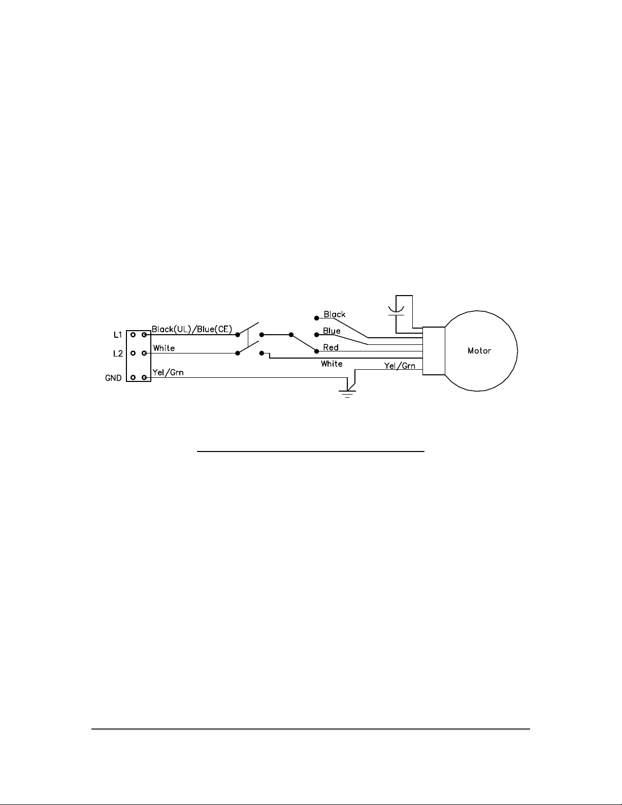
10 MAC 10 LE-AC Wiring Diagrams
Mac 10 LE-AC Three Speed Wiring Diagram
Figure 11 – Wiring Diagram Speed Control
MAC 10 LE-AC SERVICE MANUAL
61 EGAP
Page 18
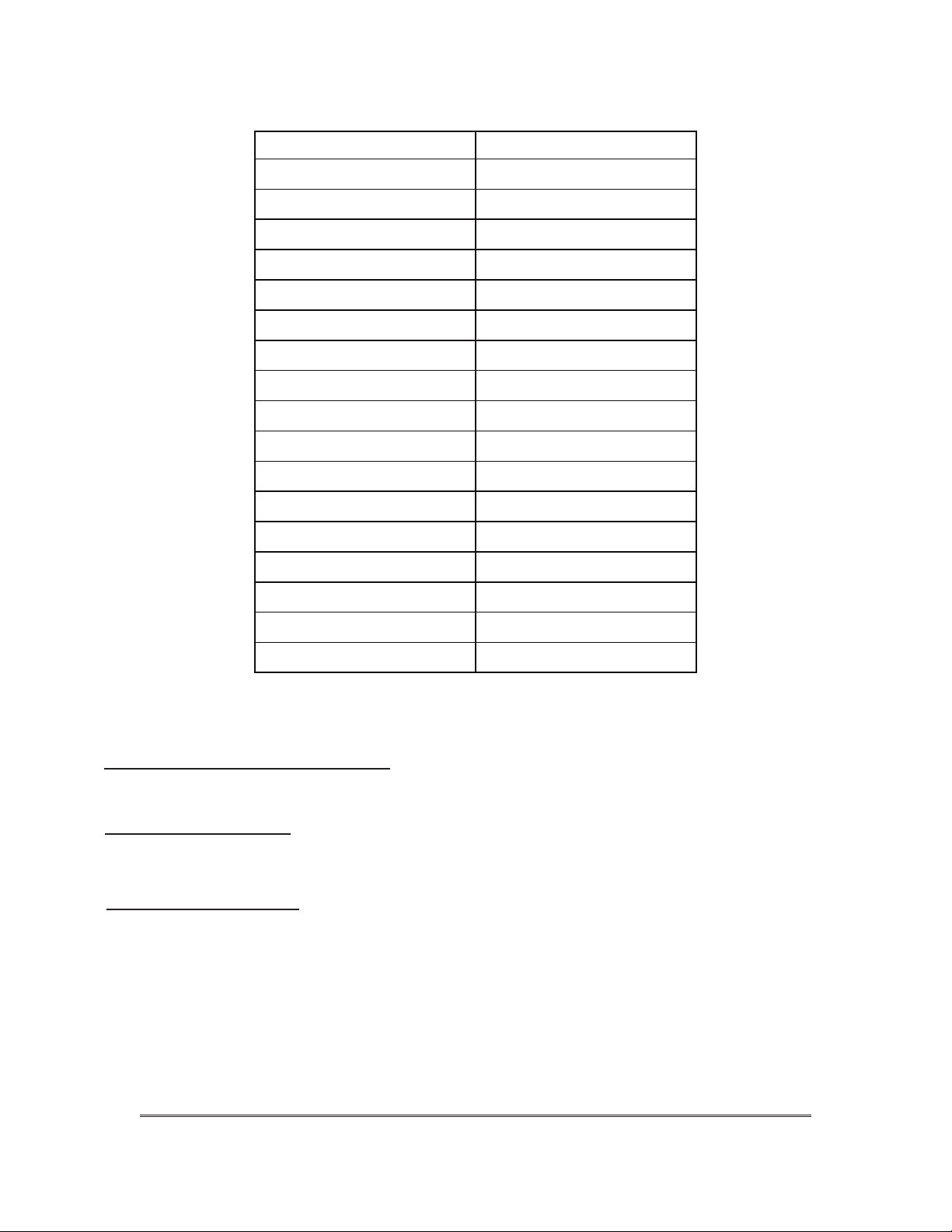
ACLE PARTS PART #
30/30 Pre filter 64125-001
11 MAC 10 LE-AC Replacement Parts List:
STANDARD FILTERS PART NUMBERS
Grommet 63271
Motor 120V 63764-001
Motor 220V 63764-002
Motor 277V 63764-003
Motor Mount Clip 38511-001
Venturi Ring 64115
Blower Wheel 64015
Motor/Blower Assy
120V 24511-001
220V 24511-002
277V 24511-003
Capacitor 61485
Capicitor Boot 60126
Rocker Switch 63739-002
3 spd switch 63775
Foam Pre-filter 62981-038
All filter part numbers are based on the standard Mac 10 sizes (2x4 – 23.63x47.63).
If the unit in question is not this
factory for replacement filter information.
69600S-001HAPXX FILTER - HEPA 2X4 9" FRAME
69600S-001UAPXX FILTER - ULPA 2X4 9" FRAME
WELDED RSR GEL SEAL
69601-001H FILTER - HEPA 21X45X3.5 GEL SEAL
69601-001U FILTER - ULPA 21X45X3.5 GEL SEAL
Optional Accessories:
Fluorescent lighting
Ionizing bar
A/C intake collar:
ULPA Filter (Standard and RSR)
Replacement parts are available through your authorized
Envirco representative. If you cannot locate a representative
in your area, contact Envirco Parts Dept. at:
20x20 (10” /254mm)
20x20 (12” /304.8mm)
20x20 (14” /355.6mm )
(20X20)
(20X20)
size or the part number includes a “Z” contact the
ENVIRCO
101 McNeill Road
Sanford, NC 27330, U.S.A.
Tel: (919) 775-2201
Tel: (800) 884-0002
Fax: (800) 458-2379
MAC 10 LE-AC SERVICE MANUAL
PAGE 71
Page 19

12 Warranty
LIMITED WARRANTY: Unless otherwise expressly stated in Envirco’s published
specifications for the Goods, Envirco warrants that that Goods are free from defects in material
and workmanship, except for services which are warranted to be performed in a competent and
diligent manner in accordance with any
mutually agreed specifications. The foregoing warranty shall apply for eighteen (18) months from
the date of shipment from Envirco’s facility, except for services for which the warranty shall apply
for ninety (90) days from the date of performance (the “Warranty Period”). Provided Buyer
informs Envirco in writing of any breach of warranty prior to the expiration of the applicable
Warranty Period, Envirco shall, as its sole obligation and Buyer’s sole and exclusive remedy for
any breach of this warranty, repair or replace/re-perform the Goods which gave rise to the breach
or, at Envirco’ option, refund the amounts paid by Buyer for the Goods which gave rise to the
breach. Any repair, replacement or re-performance by Envirco hereunder shall not extend the
applicable Warranty Period. The parties shall mutually agree on the specifications of any test to
determine the presence of a defect.
shall bear the costs of access, de-installation, re-installation and transportation of Goods to
Envirco and back to Buyer. These warranties and remedies are conditioned upon (a) the proper
storage, installation, operation, and maintenance of the Goods and conformance with the proper
operation instruction manuals provided by Envirco or its suppliers or subcontractors, (b) Buyer
keeping proper records of operation and maintenance during the applicable Warranty Period and
providing Envirco access to those records, and (c) modification or repair of the Goods only as
authorized by Envirco. Envirco does not warrant the Goods or any repaired or replacement parts
against normal wear and tear or damage caused by misuse, accident, or use against the
instructions of Envirco. Any modification or repair of any of the Goods not authorized by Envirco
shall render the warranty null and void. EXCEPT AS EXPRESSLY SET FORTH HEREIN,
ENVIRCO MAKES NO OTHER WARRANTIES, EXPRESS OR IMPLIED, INCLUDING, BUT
NOT LIMITED TO, ANY IMPLIED WARRANTIES OF MERCHANTABILITY, NONINFRINGEMENT OR FITNESS FOR A PARTICULAR PURPOSE WHICH ARE HEREBY
DISCLAIMED TO THE EXTENT PERMITTED
Unless otherwi
se agreed upon by Envirco in writing, Buyer
.
13 TESTING
Each MAC 10 LE-AC filter unit is thoroughly tested at the factory before shipment.
However, because of the “rigors” of shipping, ENVIRCO encourages its re-test after
installation. Additional, for large installations it is recommended to bench test 5% of the
units prior to installation.
ENVIRCO recommends that the customer contact an independent organization, with
technicians trained and experienced in performance evaluation and maintenance of
clean air equipment.
Some of the testing procedures performed on the MAC 10 LE-AC include PSL challenge
of HEPA/ULPA filters to assure specified performance, along with air velocity
measurement and adjustment tests. No DOP is used on Mac 10 Filters, unless
requested.
MAC 10 LE-AC SERVICE MANUAL
18 EGAP
 Loading...