

Page 1

www.envirco.com
®
H
OSPI
-G
ARD
IsoClean
And
IsoClean
®
®
UV
Operation Manual
Page 2

OSPI-GARD
H
®
ISOC
Operation Manual
LEAN
®
and ISOCLEAN
®
UV
CAUTION AND WARNINGS
READ AND SAVE THESE INSTRUCTIONS
CAUTION: To reduce the risk of fire, electrical shock or injury to persons, observe the
following:
A. Installation work and electrical wiring must be done by a qualified person(s) in accordance with
all applicable codes and standards, including fire-rated construction.
B. When cutting or drilling into a wall or ceiling, do not damage electrical wiring or other hidden
utilities.
C. Service to this equipment should be performed by authorized technicians trained and
experienced in performance evaluation and maintenance of clean air equipment. However,
certain procedures are outlined in this manual that can be performed by the owner.
D. Before servicing the unit, switch power off at service panel and lock service panel to prevent
power from being switched on accidentally, and follow proper procedures as necessary.
E. Use this unit only in the manner intended by the manufacturer. If you have questions, please
contact:
ENVIRCO CORPORATION
Envirco Office
5601 Balloon Fiesta Parkway N.E.
Albuquerque, New Mexico 87113
U.S.A.
Tel : (505) 345-3561
Fax : (505) 345-8875
Email: info@envirco.com
TRION LTD.
The Cavendish Centre
Winnall Close
Winchester, Hampshire, SO23 0LB, UK
Tel : 44 1962 840465
Fax : 44 1962 828619
Email: info@trion.co.uk
Hospi-Gard is a registered trademark of ENVIRCO Corporation
US Patents 4,560,395 and 5,470,363. Other patents issued and pending in foreign countries
IsoClean CM® is a trademark of ENVIRCO Corporation
FEDDERS INTERNATIONAL
Headquarters
No. 268 Xi Zang Road (M)
Haungpu District
Shanghai 200001
PRC
Tel : (86) 512 6258 7180
Fax : (86) 512 6258 0035
FEDDERS INTERNATIONAL, INC.
DP Computers Building
128 Joo Seng Road #05-01
Singapore 368356
Tel : 65 286 0995
Fax : 65 286 0859
i
Page 3

OSPI-GARD
H
®
ISOC
LEAN
®
and ISOCLEAN
®
UV
Operation Manual
TABLE OF CONTENTS
TITLE PAGE
1.0. Introduction ............................................................................................................................... 1
1.1. Description ...........................................................................................................................................1
1.2. Features...............................................................................................................................................1
1.3. Applications..........................................................................................................................................2
2.0. Installation ................................................................................................................................. 3
2.1. Unpacking Instructions.........................................................................................................................3
2.2. Assembly .............................................................................................................................................3
2.3. Initial Start-Up ..............................................................................................3
3.0. Operating Procedures ............................................................................................................... 4
3.1. Initial Set-Up ........................................................................................................................................4
3.2. Speed Adjustment................................................................................................................................4
3.3. Airflow Indicator ...................................................................................................................................4
3.4. Recirculation Mode ..............................................................................................................................5
3.5. Partial Exhaust/Recirculation Mode (Negative Pressure)....................................................................6
3.6. Total Exhaust Mode (Negative Pressure)............................................................................................6
3.7. Negative Pressure ...............................................................................................................................7
4.0. Maintenance and Service.......................................................................................................... 9
4.1. Parts Identification ...............................................................................................................................9
4.2. Cleaning the Unit ...............................................................................................................................11
4.3. Prefilter Replacement ........................................................................................................................11
4.4. Removal of Front and Rear Panels ...................................................................................................12
4.5. HEPA Filter Replacement ..................................................................................................................12
4.6. Power Cord........................................................................................................................................13
4.7. On/Off Switch.....................................................................................................................................13
4.8. Speed Control Switch ........................................................................................................................13
4.9. Air Pressure Switch............................................................................................................................13
4.10. Capacitor............................................................................................................................................14
4.11. Pilot Light ...........................................................................................................................................14
4.12. Motor..................................................................................................................................................14
4.13. Motor/Blower Lubrication ...................................................................................................................14
4.14. Relocating a Contaminated Unit ........................................................................................................14
4.15. Unit Decontamination.........................................................................................................................15
4.16. UV Light Tube Replacement..............................................................................................................17
5.0. Troubleshooting ...................................................................................................................... 18
5.1. Inoperative Air Flow ...........................................................................................................................18
5.2. Low Air Flow ......................................................................................................................................18
5.3. High Air Flow......................................................................................................................................18
5.4. Excessive Contamination ..................................................................................................................18
ii
Page 4

OSPI-GARD
H
®
ISOC
LEAN
®
and ISOCLEAN
®
UV
Operation Manual
6.0. Wiring Diagram........................................................................................................................ 19
6.1. Hospi-Gard® IsoClean Wiring Diagram ............................................................................................19
6.2. Hospi-Gard
®
IsoClean UV Wiring Diagram......................................................................................20
7.0. Specifications .......................................................................................................................... 21
7.1. IsoClean®...........................................................................................................................................21
7.2. IsoClean
®
UV .....................................................................................................................................21
8.0. Replacement Parts .................................................................................................................. 22
9.0. Airflow Measurement and Testing.......................................................................................... 24
10.0. Appendix.................................................................................................................................. 25
11.0. Limited Warranty ..................................................................................................................... 26
iii
Page 5

1.0. Introduction
1.1. Description
The Hospi-Gard
efficiency particulate air (HEPA) filtration system specifically designed to provide a highvelocity airflow pattern from the top face grille that creates a sweeping action to remove
airborne particulate. In addition to recirculating clean air, it can simultaneously exhaust
air out of the room to create negative pressure. An optional 8-inch exhaust collar is
available to convert the IsoClean
Air enters the module through the intake grille located on the lower section of the unit.
The air is evenly drawn by the blower first through a prefilter and then through a HEPA
filter. The HEPA filter is 99.99% efficient at removing particles 0.3 microns and larger.
The air moves at a volume of 550 cubic feet per minute (CFM) on low, 700 CFM on
medium and up to 800 CFM on high to carry away airborne particulate generated by
activities within the room.
OSPI-GARD
H
IsoClean® and IsoClean® UV are portable, self-contained high-
®
ISOC
Operation Manual
LEAN
®
and ISOCLEAN
INTRODUCTION
®
to a complete exhausting system.
®
UV
The IsoClean
caught on the HEPA filter surface and in the air prior to recirculation back into the room.
1.2. Features
The Hospi-Gard IsoClean® can be used as a total recirculating air system, as a total
•
air exhaust system (using the optional 8-in. exhaust collar) or as a split system with
partial air recirculation and partial air exhaust.
The Hospi-Gard IsoClean® can easily and economically convert a standard room
•
into a negative pressure, patient isolation room.
Provides 27 air changes per hour in a typical patient room of 18 feet x 12 feet x 8 feet.
•
The three-speed adjustable airflow control allows effective use in a variety of room
•
sizes.
High discharge air velocity with a high-to-low airflow pattern assures adequate “reach”
•
and air circulation, preventing “short circuiting.”
Quiet operation. 52 dBA at low, 56 at medium and 60 at high speed measured 30 in.
•
from face of unit.
HEPA filter and prefilter are easy to replace.
•
®
UV offers the added benefits of ultraviolet irradiation of the particulate
Page 1
Page 6

H
1.3. Applications
Hospital
Convert Patient Rooms to Negative Pressure Isolation Rooms
•
Waiting Rooms
•
Bronchoscopy Rooms
•
Emergency Rooms
•
Intensive Care Units
•
Sputum Induction Booths and Rooms
•
Aerosol Pentamidine Booths and Rooms
•
Renal Dialysis Treatment Rooms
•
Hospital Reconstruction Areas
•
Other
OSPI-GARD
®
ISOC
LEAN
Operation Manual
®
and ISOCLEAN
®
UV
Clinics
•
Physician Offices
•
Correctional Facilities
•
Nursing Homes
•
Homeless Shelters
•
Addiction Recovery Center
•
Page 2
Page 7

2.0. Installation
2.1. Unpacking Instructions
2.1.1. The Hospi-Gard
2.1.2. Uncrate and remove all packing material. Examine the unit for internal damage.
2.2. Assembly
OSPI-GARD
H
®
ISOC
Operation Manual
LEAN
®
and ISOCLEAN
®
UV
INSTALLATION
IsoClean® is shipped in an open-framed crate. The module
should be inspected for exterior shipping damage immediately upon arrival. If
any damage is observed, a claims report should be completed and promptly filed
with the responsible carrier.
If damage is discovered inside the crating, file a claim with the responsible carrier
immediately. The shipping components list and actual material received should
be compared and any shortages reported to Envirco immediately.
2.2.1. The Hospi-Gard
and requires no assembly. Every unit is tested prior to shipment to verify airflow,
noise level and that the unit is leak-free.
2.2.2. Place the unit in its final operating position (see Figure 1 in section 3.4. for
recommended positioning).
2.2.3. Lock the wheel locks on the casters to keep the unit from accidental repositioning.
2.3. Initial Start-Up
NOTE: The CDC requires that quantitative leakage and filter performance tests be
performed at the initial installation and every time the filter is changed or
moved. Tests should be repeated every six months. The factory tests should
not be substituted for the initial test.
IsoClean® is shipped completely assembled from the factory
Page 3
Page 8

OSPI-GARD
H
OPERATING PROCEDURES
3.0. Operating Procedures
3.1. Initial Set-Up
3.1.1. Connect the power cord to a standard 115-Volt, Single Phase, 60 Hertz,
grounded power source. Assure that the circuit is sized to provide sufficient
amperage as noted on the Hospi-Gard
3.1.2. Locate the “ON/OFF” switch on the right side of the unit. The switch is a
maintain contact rocker type.
3.1.3. Turn the Hospi-Gard
portion of the rocker switch. A slight whirring sound will be heard as the motor
starts. Within 5 to 10 seconds, the module will start to provide clean air into the
environment.
®
ISOC
Operation Manual
IsoClean® unit on by pressing downward on the raised
LEAN
®
and ISOCLEAN
IsoClean® data plate.
®
UV
3.2. Speed Adjustment
NOTE: The Hospi-Gard
3.2.1. To change speeds, remove the exhaust grille by pulling down and lifting out.
3.2.2. Turn the 3-speed switch to the desired setting.
3.2.3. Replace the exhaust grille.
3.3. Airflow Indicator
3.3.1. Locate the airflow indicator on the right side of the unit above the “ON/OFF”
switch. On high speed, the light will turn on when there is sufficient pressure,
indicating the need for a filter change. The airflow indicator should not be used as
the only guide for when a filter change is necessary. The unit should be checked
on a periodic basis to insure recommended room air changes per hour are being
met.
3.3.2. The air velocity generated by the unit may be checked using an airflow
measurement device. The volume of air entering the lower intake grille should
be approximately 550 CFM on low, 700 CFM on medium and 800 CFM on high
with a new filter. See Section 9 for the recommended airflow measurement
procedure.
IsoClean unit is set on low at the factory.
Page 4
Page 9
OSPI-GARD
H
3.4. Recirculation Mode
®
ISOC
LEAN
Operation Manual
®
and ISOCLEAN
®
UV
3.4.1. The Hospi-Gard
IsoClean® unit is set at the factory on the 100% air recirculation
mode.
3.4.2. The room air change rate of the unit will depend on both the Hospi-Gard
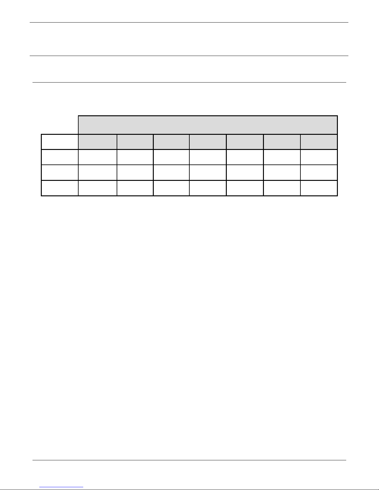
IsoClean® speed setting and the size of the room. See Table 1 in the Appendix
for representative room air changes per hour (ACH).
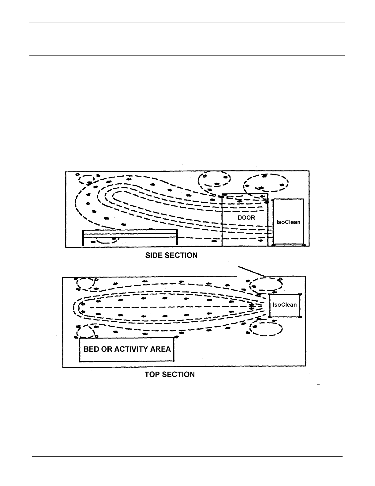
3.4.3. For maximum recirculation efficiency, the unit should be placed between the
entry door and the patient’s bed or the activity area (see Figure 1 below).
However, the unit will function effectively at other locations within the room.
Figure 1: Recommended Hospi-Gard
IsoClean® Positioning within a Patient Room
Page 5
Page 10

OSPI-GARD
H
®
ISOC
LEAN
®
and ISOCLEAN
®
Operation Manual
3.5. Partial Exhaust/Recirculation Mode (Negative Pressure)
UV
NOTE: The IsoClean
®
and IsoClean® UV units come with a removable Exhaust Cover
Plate and a removable 6-inch Duct Collar for attachment to exhaust ducting
(not included) to create a negative pressure room. If the Exhaust Cover Plate
is not removed, both the IsoClean
®
and IsoClean® UV units will operate in the
100% recirculation mode.
3.5.1. Remove the Exhaust Cover Plate located on top of the IsoClean
®
unit by taking
off the four (4) screws and plastic caps used to secure the cover to the IsoClean
exhaust port.
3.5.2. Remove the 6-inch duct collar underneath the top cover and flip the collar over.
3.5.3. Attach exhaust ducting (not included) onto the collar and fasten tightly with a
round hose clamp (not included).
®
3.5.4. Mount the duct collar with ducting onto the IsoClean
exhaust port using the four
(4) screws that originally held the cover plate.
NOTE: Keep the top plate and plastic washers for re-assembly when needed.
3.5.5. The HEPA filtered exhaust air can now be vented to the outside or returned to
the main HVAC system
1
. If the unit is ducted to an exhaust duct rather than
directly to the outside, it must be verified that the exhaust duct is capable of
handling the exhaust air expelled by the unit.
®
3.5.6. The IsoClean
®
is designed to exhaust 100-300 CFM at the 6-inch exhaust port. It
is recommended that the unit be set on the high-speed setting when operating in
this mode to achieve maximum exhaust and negative pressure. At this setting,
the IsoClean
®
will exhaust approximately 300 CFM and recirculate 500 CFM.
3.6. Total Exhaust Mode (Negative Pressure)
NOTE: The cover plate must be securely attached to the top of the IsoClean
®
for the
unit to run in the 100% exhaust mode.
3.6.1. An optional 8-inch Exhaust Collar with Flange (Part No. 11055) is available to
convert the IsoClean
®
unit to the 100% exhaust mode.
3.6.1.1. Remove the front exhaust grille by pulling down and lifting out.
3.6.1.2. Place the optional 8-inch exhaust collar over the opening where the
grille was removed and attach with the screws included with the 8-inch
collar.
3.6.1.3. Attach flexible exhaust duct (not included) over the 8-inch collar and
fasten tightly with a round hose clamp (not included).
__________________________________________________________________________________
1
CDC recommends that air from negative pressure rooms be exhausted to the outside in accordance with federal, state and local
regulations. The air should not be recirculated into the general ventilation. In certain cases in existing facilities, recirculation of air into the
general ventilation system is unavoidable and, in such cases, CDC guidelines state that HEPA filters should be installed in the exhaust
duct leading from the room to the general ventilation system.
Page 6
Page 11

OSPI-GARD
H
®
ISOC
LEAN
Operation Manual
®
and ISOCLEAN
®
UV
3.6.1.4. The HEPA filtered exhaust air can now be vented to the outside or
returned to the main HVAC system
2
. If the unit is ducted to an exhaust
duct rather than directly to the outside, it must be verified that the
exhaust duct is capable of handling the exhaust air expelled by the unit.
3.6.2. An optional 8-inch Duct Collar (Part No. 23877-002P) and Front Exhaust Cover
(Part No. 38236-001P) must be purchased separately to convert the IsoClean
UV unit to the 100% exhaust mode.
®
3.6.2.1. Remove the Exhaust Cover Plate for the IsoClean
of the IsoClean
used to secure the cover to the IsoClean
3.6.2.2. Replace the Exhaust Cover Plate with the optional 8-inch Duct Collar
and secure it to the IsoClean
®
UV by taking off the four (4) screws and plastic caps
®
UV using the four (4) screws that
®
UV exhaust port.
UV located on top
originally held the Cover Plate.
3.6.2.3. Remove the Front Exhaust Grille and replace with the Front Exhaust
Cover.
3.6.2.4. Attach flexible exhaust duct (not included) over the 8-inch collar and
fasten tightly with a round hose clamp (not included).
3.6.2.5. The HEPA filtered exhaust air can now be vented to the outside or
returned to the main HVAC system
3
. If the unit is ducted to an exhaust
duct rather than directly to the outside, it must be verified that the
exhaust duct is capable of handling the exhaust air expelled by the unit.
®
3.7. Negative Pressure
NOTE: CDC Guidelines recommend that rooms used for negative pressure isolation
should be single patient rooms with negative pressure relative to the corridor or
other areas connected to the room. The minimum pressure difference
necessary to achieve and maintain negative pressure that will result in airflow
into the room is 0.01 inch W.G. (a higher pressure is preferred). To achieve
this, the exhaust flow should be 10% or 50 CFM greater than the supply
(whichever is greater).
3.7.1. Achieving Negative Pressure
3.7.1.1. The IsoClean
®
unit is designed to exhaust 100-300 CFM when the
6-inch exhaust collar is used. It is recommended that the unit be set on
the high-speed setting when operating in this mode to achieve
maximum exhaust and negative pressure. At this setting, the IsoClean
will exhaust approximately 300 CFM and recirculate 500 CFM.
__________________________________________________________________________________
2
CDC recommends that air from negative pressure rooms be exhausted to the outside in accordance with federal, state and local
regulations. The air should not be recirculated into the general ventilation. In certain cases in existing facilities, recirculation of air into the
general ventilation system is unavoidable and, in such cases, CDC guidelines state that HEPA filters should be installed in the exhaust
duct leading from the room to the general ventilation system.
3
CDC recommends that air from negative pressure rooms be exhausted to the outside in accordance with federal, state and local
regulations. The air should not be recirculated into the general ventilation. In certain cases in existing facilities, recirculation of air into the
general ventilation system is unavoidable and, in such cases, CDC guidelines state that HEPA filters should be installed in the exhaust
duct leading from the room to the general ventilation system.
®
Page 7
Page 12

OSPI-GARD
H
®
ISOC
Operation Manual
LEAN
®
and ISOCLEAN
3.7.1.2. If an exhaust volume greater than 300 CFM is required to create a
negative pressure room, the optional 8-inch 100% exhaust collar (Part
No. 11055) should be used as described in Section 3.6.
3.7.1.3. The attachment of ductwork to the exhaust port decreases the air
volume exhausted through the port. The magnitude of the decrease
varies depending on the length and type of duct as well as its
configuration. For example, for a 10-foot run of standard flexible duct
containing two 90-degree bends, the exhaust reduction will be
approximately 100 CFM.
NOTE: It is the responsibility of the purchaser and not Envirco Corporation to
ensure the room in which the unit is used is in compliance with CDC
Guidelines
4
for a negative pressure isolation room and monitored to
ensure its continuing performance.
3.7.2. Difficulty Achieving Negative Pressure
®
UV
The equipment may not be able to achieve or maintain negative pressure in
conformance with the CDC Guidelines4 due to building ventilation of rooms or air
leakage. The room should be inspected for air leakage through doors, windows,
plumbing and wall penetrations. Appropriate corrective action should be taken to
seal the leaks.
__________________________________________________________________________________
4
CDC. Guidelines for Preventing the Transmission of Tuberculosis in Health-Care Facilities, 1994. MMWR, October 28, 1994; 43
(No. RR-13.)
Page 8
Page 13
OSPI-GARD
H
MAINTENANCE AND SERVICE
4.0. Maintenance and Service
4.1. Parts Identification
®
ISOC
LEAN
Operation Manual
®
and ISOCLEAN
®
UV
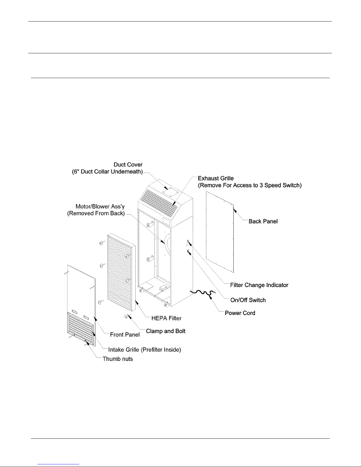
4.1.1. Hospi-Gard
IsoClean
®
Figure 2: Hospi-Gard
IsoClean® Parts Location
Page 9
Page 14
OSPI-GARD
H
®
ISOC
LEAN
Operation Manual
®
and ISOCLEAN
®
UV
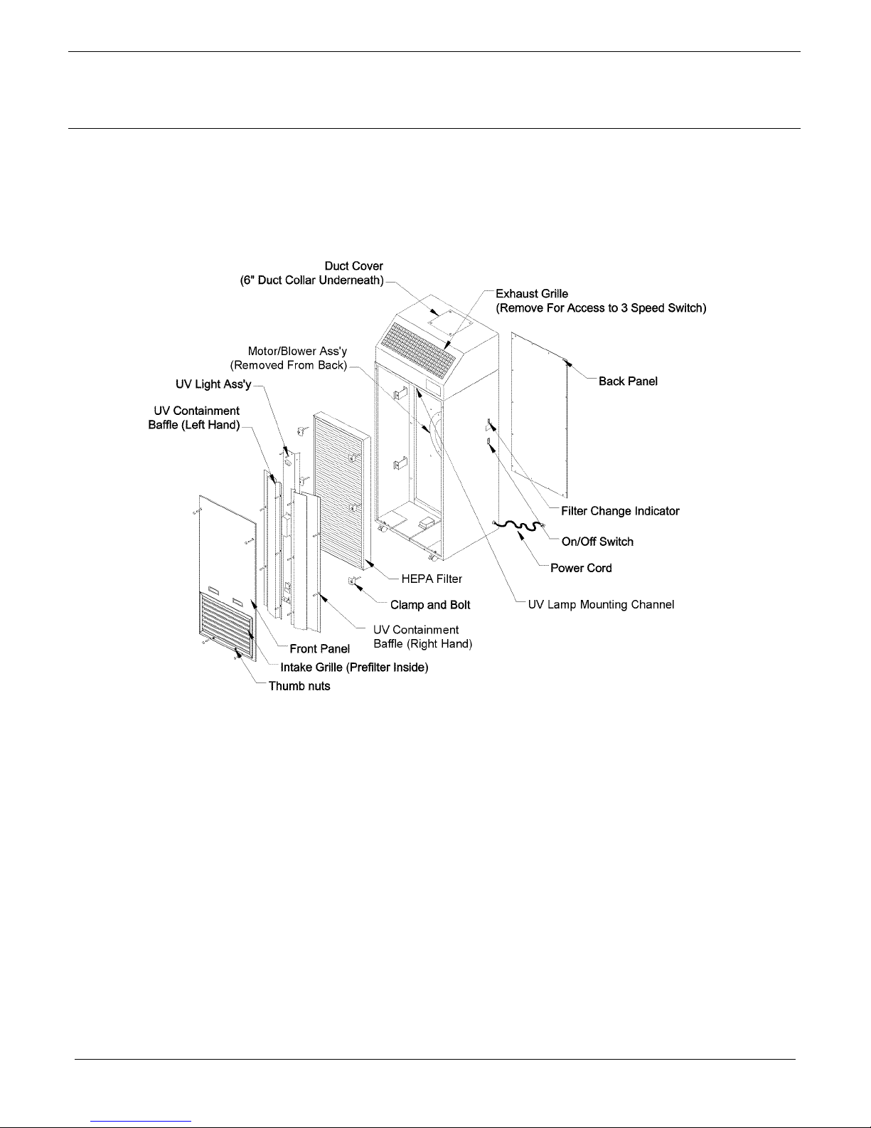
4.1.2. Hospi-Gard
IsoClean® UV
Figure 3: Hospi-Gard
IsoClean® UV Parts Location
Page 10
Page 15

OSPI-GARD
H
®
ISOC
Operation Manual
LEAN
®
and ISOCLEAN
®
UV
CAUTION: Proper protective equipment and measures must be used at all times
during unit cleaning and maintenance. Check with your Safety Office to
assure the cleaning solutions, protective equipment (disposable hospital
gown, HEPA respirator, protective gloves) and protocols followed comply
with your facility’s and CDC guidelines.
CAUTION: Disconnect the unit from the electrical power source before attempting
service. Do not work inside the IsoClean
®
UV with the UV light on. Proper
replacement of UV containment baffles, after maintenance, is mandatory to
maintain safe short-term and long-term UV exposure levels.
4.2. Cleaning the Unit
4.2.1. Periodic cleaning of the unit may be done with a mild disinfecting soap and water
solution. A 1% or 1/100 dilution of bleach is an optional disinfectant
5
.
4.2.2. Cleaning must be performed with the unit running. Wipe the exterior of the unit
with a damp sponge or cloth, paying particular attention to the prefilter intake
grille.
4.3. Prefilter Replacement
4.3.1. The prefilter should be replaced every 60 to 90 days. Regularly replacing the
prefilter will maximize the life of the HEPA filter.
The IsoClean
®
UV comes standard with an anti-microbial pleated prefilter. It is
recommended that a pleated prefilter is used to insure that safe long-term
recommended exposure levels to UV are maintained.
4.3.2. Wipe the unit as described in Section 4.2.
4.3.3. Spray a mist of phenolic disinfectant such as “Amplyl” or “Lysol” into the air
intake grille.
4.3.4. Remove the two (2) thumb nuts from the face of the intake grille and pull the
grille out.
4.3.5. Insert gloved hand into a red plastic, medical waste disposal bag. Grasp the top
portion of the prefilter with bagged hand and gently pull outward. The airflow of
the unit will offer a resistance to pulling the prefilter out.
4.3.6. Turn the bag inside out over the prefilter then seal the bag for containment.
4.3.7. Install a new prefilter and close the grille up in the reverse order of removal.
__________________________________________________________________________________
5
Rutala WA, APIC guideline for selection and use of disinfectants, Am J Infect Control 1996 Aug ; 24(4): 313-42.
Page 11
Page 16

OSPI-GARD
H
®
ISOC
Operation Manual
LEAN
®
and ISOCLEAN
®
UV
CAUTION: Appropriate decontamination procedures (see Section 4.15 must be
followed prior to removal of the access panels to replace the HEPA filter or
other parts. Contact your Safety Office to assure it conforms to your
facility’s protocol.
4.4. Removal of Front and Rear Panels
4.4.1. Remove the front access panel by taking off the screw covers and removing the
four (4) screws. The front panel may now be lifted off.
4.4.2. Remove the 18 screws securing the rear access panel. The rear panel may now
be lifted off.
4.5. HEPA Filter Replacement
The CDC recommends that in any application, HEPA filters should be maintained
meticulously and should be carefully installed by adequately trained personnel wearing
an appropriate respirator. A regular maintenance program should include procedures for
installation, removal and disposal of filter elements and a program to monitor the HEPA
filter for possible leakage and for filter loading.
4.5.1. The expected HEPA filter life should range from 18 months to two (2) years
depending on the environment and prefilter maintenance schedule. The filter
indicator light will give a warning of filter loading by flickering on high speed.
When the light stays lit on high speed, the HEPA filter should be changed.
4.5.2. Remove the prefilter as described in Section 4.3.
4.5.3. Remove the front access panel as described in Section 4.4. Lift the panel out
and set it aside.
4.5.4. Removal of the UV Light Assembly for the IsoClean
®
UV
4.5.4.1. Remove the five (5) screws on the left hand UV containment baffle and
the five (5) screws on the right hand containment baffle and remove the
baffle assemblies.
4.5.4.2. Disconnect the three-pin connector located near the UV lamp ballast
and remove the wires from the wire routing clamp.
4.5.4.3. Remove the four (4) screws, washers and nuts holding the UV lamp
assembly in place (the mounting channel may be removed or left in
place). Access through the exhaust grille is necessary to remove the
mounting channel. Remove the exhaust grille by pushing down and
lifting out. Carefully remove the UV lamp assembly taking care not to
touch the glass tube.
NOTE: Clean the UV light tube as necessary, using a cloth dampened with an
10% alcohol (or ammonia) and water solution, to avoid lamp
degradation due to oil and dust residues.
Page 12
Page 17

H
4.5.5. Remove the six (6) bolts and clamps holding the HEPA filter. Slip a plastic
biohazard bag over the filter from the top down. Tilt the top of the filter downward
and wrap the bag over the bottom of the HEPA filter. Seal the bag to for
containment.
NOTE: It may be necessary to use two (2) biohazard bags to fully contain the
4.5.6. Remove the new HEPA filter from its container and install it in the reverse order
of removal. Care must be taken when handling the HEPA filter. Do not bump or
squeeze the filter as this may damage the filter and render it non-effective.
4.6. Power Cord
4.6.1. With the back panel removed, unplug the white connector on the power cord.
4.6.2. Remove nut on ground wire.
4.6.3. Remove strain relief on the side of the unit.
4.6.4. Remove the old cord and replace with the new one, following the steps above in
reverse order.
OSPI-GARD
filter.
®
ISOC
LEAN
Operation Manual
®
and ISOCLEAN
®
UV
4.7. On/Off Switch
4.7.1. With the back panel removed, unplug the white connector on the switch and
squeeze the retainer strips on switch bezel.
4.7.2. Remove retaining nut that holds the switch to the baffle panel.
4.7.3. Unplug all connecting wires and replace the new switch, following the steps
above in reverse order.
4.8. Speed Control Switch
4.8.1. Remove the exhaust grille by pushing down and lifting out.
4.8.2. Remove the retaining nut that holds the switch to the baffle panel.
4.7.3. Unplug all connecting wires and replace with the new switch, following the steps
above in reverse order.
4.9. Air Pressure Switch
4.9.1. With the back panel removed, disconnect the two (2) air supply tubes and two (2)
electric terminals.
4.9.2. Remove the two (2) sheet metal screws and replace with the new switch, making
sure to reconnect everything correctly.
Page 13
Page 18

4.10. Capacitor
4.10.1. With the back panel removed, remove one screw from capacitor strap.
4.10.2. Slide capacitor out.
4.10.3. Remove the rubber boot and disconnect wires.
4.10.4. Replace with the new capacitor, following the steps above in reverse order.
4.11. Pilot Light
4.11.1 With the back panel removed, disconnect the 3-pin connector and push out
pilot light from the inside of the unit.
4.11.2 Replace the pilot light, following the step above in reverse order.
4.12. Motor
4.12.1. With the back panel removed, disconnect all wire connections between the
motor and other components.
4.12.2. Loosen the Allen Head Set screws on the blower wheel hub and remove the
wheel.
OSPI-GARD
H
®
ISOC
LEAN
Operation Manual
®
and ISOCLEAN
®
UV
4.12.3. Loosen the screw on the motor belly band until the motor can slide out.
4.12.4. Replace with the new motor, following the steps above in reverse order,
ensuring there is an ⅛-inch to ¼-inch gap between the blower wheel and the
inlet ring.
CAUTION: When reinstalling the motor ensure that it does not touch or puncture the
HEPA filter.
4.13. Motor/Blower Lubrication
The IsoClean
unit is equipped with permanently sealed bearings and requires no
lubrication.
4.14. Relocating a Contaminated Unit
NOTE: Use proper protocol, gowning and protective measures.
4.14.1. If an existing unit is to be placed into storage for an extended period of time,
remove and replace the prefilter as described in Section 4.3.
4.14.2. Turn the unit off and disconnect from power source.
4.14.3. Clean the exterior surfaces of the unit as described in Section 4.2.
4.14.4. Unlock caster wheel locks and move unit to its new location.
Page 14
Page 19

OSPI-GARD
H
4.15. Unit Decontamination
NOTE: Use proper protocol, gowning and protective measures during unit
decontamination.
Should decontamination of the unit be required, the following is an adaptation by
Annex G. of the Recommended Microbiological Decontamination Procedure from NSF
49, May 1992. Confirm with appropriate Biosafety and Industrial Safety Professionals
that the procedures meet your facility’s guidelines.
4.15.1. Paraformaldehyde Decontamination
4.15.1.1. Relocate the unit as described in Section 4.14 to a controlled
access, non-public area with a non-porous floor, good ventilation
and a dedicated exhaust directly outside the building. A new
prefilter is not required. Attach and seal a flexible hose to the
dedicated exhaust. Place the other end of the exhaust hose near
the unit.
®
ISOC
LEAN
Operation Manual
®
and ISOCLEAN
®
UV
4.15.1.2. Calculate the total volume of the unit by multiplying the height, width
and depth. The total IsoClean
volume is 13 cubic feet (61 in. x 24
in. x 15.5 in.).
3
4.15.1.3. Multiply the total volume of the unit by 0.3g/ft
to determine the gram
weight of Paraformaldehyde required. Decontamination of the
IsoClean
requires 3.9 grams (12 ft3 x 0.3g/ ft3) of
Paraformaldehyde.
4.15.1.4. Remove the intake grille and wipe it down with an appropriate
surface decontaminant.
4.15.1.5. Place an unplugged heating device, such as a commercially
available electric frying pan with the thermostat set at 232.2º to
246.1º C (450º to 475º F) inside the unit through the removed
prefilter access panel. Spread the Paraformaldehyde evenly over
the heating surface of the electric frying pan.
o
CAUTION: The auto-ignition temperature of Paraformaldehyde is 300
o
(572
F). Place a hot plate, beaker of water, and temperature
C
and humidity indicators in the unit next to the pan that will
contain the Paraformaldehyde.
4.15.1.6. Enclose all sides of the unit with heavy gauge plastic film and tape
in place while leaving the film that will close the space formerly
occupied by the intake grille free. The power cord should be coiled
and taped to the unit and sealed under the plastic film. Seal the film
to the floor on which the unit stands.
4.15.1.7. Determine the temperature and humidity inside the unit.
Page 15
Page 20

OSPI-GARD
H
®
ISOC
LEAN
Operation Manual
®
and ISOCLEAN
®
UV
4.15.1.8. The temperature should be 21.1
o
C (70
o
F) or higher with a humidity
level between 60% to 85%. Use the hot plate to heat the beaker of
water until the desired temperature and humidity are achieved.
Disconnect the hot plate.
4.15.1.9. Seal the film over the remaining opening of the intake grille space.
Carefully seal around the power cord extending from the electric
frying pan so that formaldehyde gas will not leak out.
4.15.1.10. Plug the cord of the electric frying pan into an outlet.
4.15.1.11. After the Paraformaldehyde has depolymerized, disconnect the
frying pan from the electrical outlet.
4.15.1.12. Allow the unit to stand for a minimum of two hours or overnight.
4.15.1.13. Attach the flexible hose to the unit and allow it to draw from inside
the unit.
4.15.1.14. After 15 minutes of visible exhaust activity, small openings may be
made in the film over the unit’s air supply grille to improve
ventilation.
4.15.1.15. Allow the unit to ventilate overnight.
4.15.1.16. Remove the unit from exhaust ventilation when the formaldehyde
gas has been exhausted.
CAUTION: During unit decontamination, respiratory protection for
service personnel is recommended. Only National Institute
for Occupational Safety and Health (NIOSH) approved
respirators should be used.
4.15.1.17. Remove the HEPA filter as described in Section 4.5. The filter can
now be disposed of as general waste.
4.15.2. Phenolic Decontamination
In facilities where Paraformaldehyde gas decontamination is prohibited or not
feasible, the unit can be disinfected by the following procedure.
4.14.2.1. Remove the prefilter as described in Section 4.3.
4.14.2.2. After the intake grille and prefilter are removed, turn the unit on, and
with the unit running, spray a mist of phenolic disinfectant such as
Amphyl or Lysol into the air intake opening. Approximately two (2)
to five (5) ounces is adequate.
4.14.2.3. Remove the HEPA filter as described in the Section 4.5. Since the
filter has not been decontaminated by the formaldehyde procedure,
it must be placed in a red medical waste bag and disposed of
properly.
Page 16
Page 21

OSPI-GARD
H
®
ISOC
4.16. UV Light Tube Replacement
4.16.1. The expected life of the UV light tube is nine (9) months to one (1) year
depending on the environment and prefilter maintenance schedule.
4.16.2. Remove the five (5) screws on the left hand UV containment baffle or the five
(5) screws on the right hand containment baffle and remove the baffle
assembly.
4.16.3. Reach around the UV light assembly, taking care not to touch the face of the
HEPA filter, and grasp the “old” light tube gently. Rotate the light tube 90
degrees in either direction to enable removal (you should feel tension on the
tube release). To remove the light tube, carefully pull away from the UV lamp
assembly, towards the HEPA filter. Dispose of the light tube (or recycle)
following local guidelines.
CAUTION: Touching the face of the filter could cause damage to the filter media
resulting in the need of professional repair or replacement.
4.16.4. Use clean latex gloves to insure that the new light tube remains clean. Clean
the new light tube using a cloth dampened with a 10% alcohol (or ammonia)
and water solution. To replace, reverse the order of removal.
®
LEAN
Operation Manual
and ISOCLEAN
®
UV
Page 17
Page 22

OSPI-GARD
H
5.0. Troubleshooting
NOTE: Before attempting to service and repair the unit, use proper protocol and follow
appropriate decontamination procedures described in the following sections:
Section 4.2 Cleaning the Unit
Section 4.3 Prefilter Replacement
Section 4.14 Relocating a Contaminated Unit
Section 4.15 Unit Decontamination
5.1. Inoperative Air Flow
5.1.1. Confirm that the power cord is plugged into the building receptacle and power is
present.
®
ISOC
Operation Manual
LEAN
®
and ISOCLEAN
TROUBLESHOOTING
®
UV
5.1.2. Confirm that the unit power switch is turned “ON.”
5.1.3. Check switch and internal wiring per Wiring Diagram (Section 6). Replace or
repair faulty component(s).
5.1.4. Check the motor and replace if necessary.
5.1.5. Check the motor capacitor and replace if necessary.
5.2. Low Air Flow
5.2.1. Check prefilter for obstruction and remove obstruction as necessary
(Section 4.3).
5.2.2. Replace dirty prefilter media.
5.2.3. Switch the speed control to the next higher airflow setting.
5.2.4. Check power supply for proper voltage, amperage and distribution frequency.
5.2.5. Check for down-stream obstructions or erratic isolation room ventilation balance.
5.2.6. Replace HEPA filter if the air velocity remains low (Section 4.5).
5.3. High Air Flow
5.3.1. Adjust the speed control down to the next lowest setting.
5.3.2. Assure all filters are properly in place.
5.4. Excessive Contamination
5.4.1. Replace HEPA filter (Section 4.5.)
5.4.2. Assure the HEPA filter is installed properly.
Page 18
Page 23
H
6.0. Wiring Diagram
OSPI-GARD
®
ISOC
Operation Manual
LEAN
®
and ISOCLEAN
WIRING DIAGRAM
®
UV
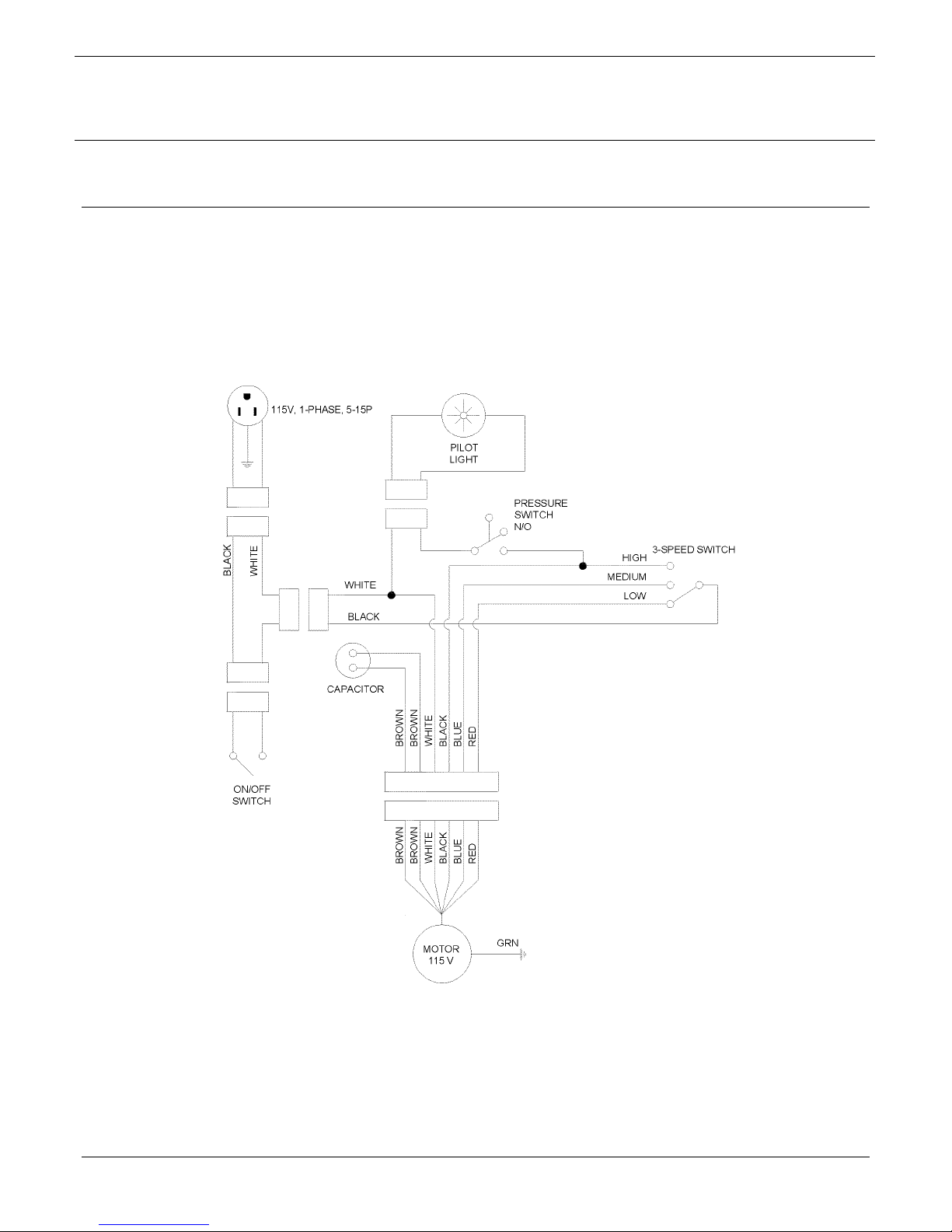
6.1. Hospi-Gard® IsoClean
Wiring Diagram
Figure 4: Hospi-Gard® IsoClean
Page 19
Wiring Diagram
Page 24
OSPI-GARD
H
®
ISOC
LEAN
Operation Manual
®
and ISOCLEAN
®
UV
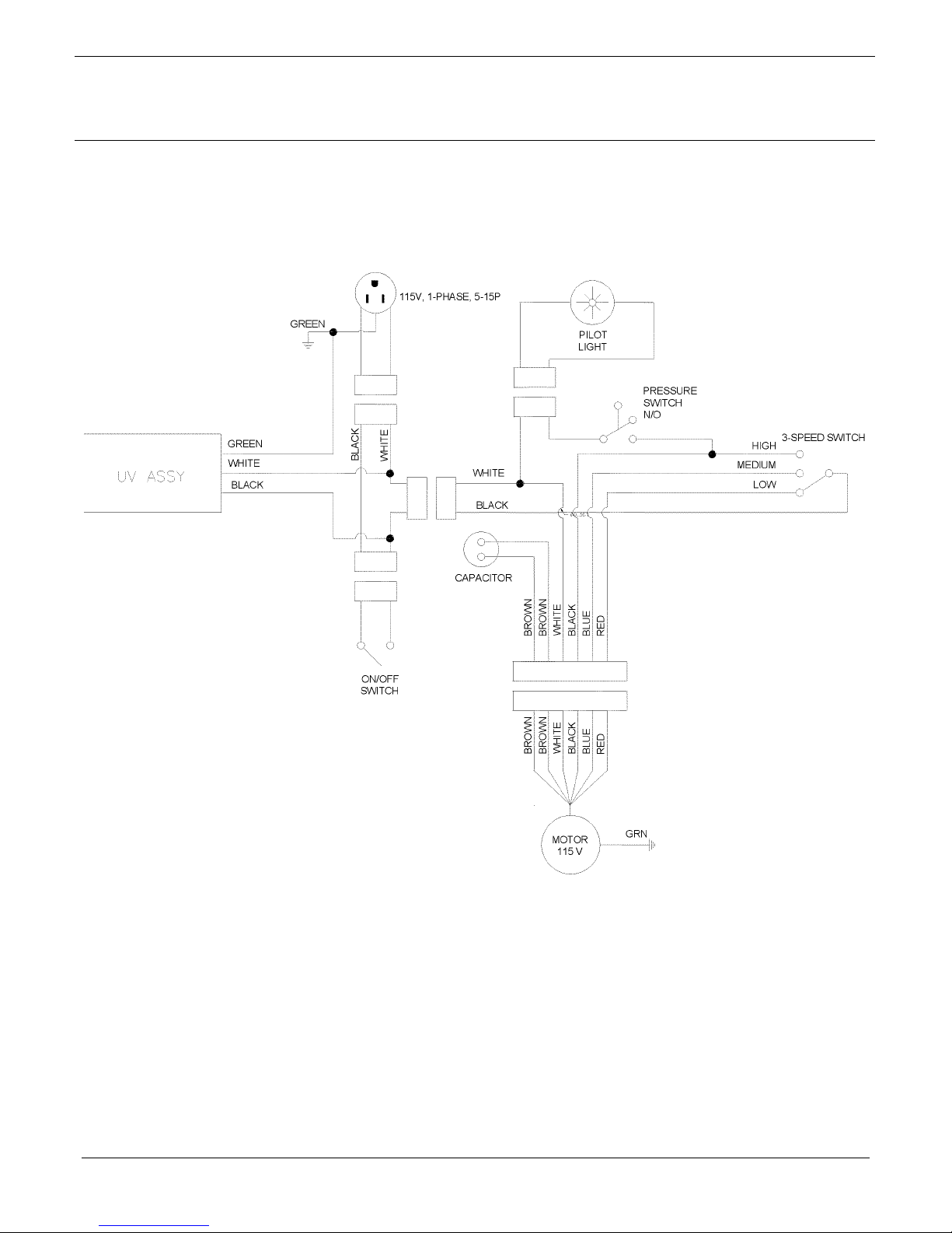
6.2. Hospi-Gard® IsoClean
UV Wiring Diagram
Figure 5: Hospi-Gard® IsoClean® UV Wiring Diagram
Page 20
Page 25

7.0. Specifications
7.1. IsoClean® (10850)
Dimensions: 62.25 H x 23.75 W x 15.75 D In.
Weight: 175 lbs. (ship weight)
Power Requirements: 7.0 A at 115 V, 60 Hz, Single Phase
Average Airflow: 550 CFM on Low
HEPA Filter Media: 99.99% at 0.3 micron minimum efficiency
Prefilter: Woven polyester with frame
Motor: 1/3 Hp, direct drive, three-speed, continuous duty
Exhaust Port: 6-Inch Duct Collar
OSPI-GARD
H
®
ISOC
Operation Manual
LEAN
®
and ISOCLEAN
SPECIFICATIONS
158.2 H x 60.4 W x 40.0 D cm
78 kg
700 CFM on Medium
800 CFM on High
®
UV
7.2. IsoClean® UV (10850-005)
Dimensions: 62.25 H x 23.75 W x 19.5 D In.
Weight: 200 lbs. (ship weight)
Power Requirements: 8.0 A at 115 V, 60 Hz, Single Phase
Average Airflow: 550 CFM on Low
HEPA Filter Media: 99.99% at 0.3 micron minimum efficiency
Prefilter: Anti-microbial pleated prefilter with frame
Motor: 1/3 Hp, direct drive, three-speed, continuous duty
Exhaust Port: 6-inch Duct Collar
158.2 H x 60.4 W x 50.2 D cm
89 kg
700 CFM on Medium
800 CFM on High
Page 21
Page 26

OSPI-GARD
H
8.0. Replacement Parts
8.1. IsoClean® (10850)
®
ISOC
LEAN
®
and ISOCLEAN
Operation Manual
REPLACEMENT PARTS
®
UV
Part No.
Description Quantity
62954 Motor, 1/3 HP, 3 speed 115V 1
62964 Air Inlet Ring 1
62978 Blower Wheel 1
62944 3-Speed Switch 1
63042-008 Power Cord – Molded 115V 1
61807
Motor Capacitor 15µf
1
66354 On-Off Switch 1
63027 Air Pressure Switch 1
61400 Filter Pilot Light 1
90833 Prefilter 12”x20”x1” 1
69391-001 HEPA Filter 21”x45”x3” 1
62973 Caster 2
62974 Caster with Brake 2
23877 6-inch Duct Collar for IsoClean
37454 Exhaust Cover Plate for IsoClean
Part No.
Optional Accessories Quantity
®
®
1
1
11055 8-in. A/C Collar with Flange for 100% Exhaust (IsoClean®)1
63338 Annunciator 1
63352 Antimicrobial Prefilter 1
63349 Carbon Prefilter 1
63337 Room Pressure Monitor 1
To place a direct order:
ENVIRCO CORPORATION
Envirco Office
5601 Balloon Fiesta Parkway N.E.
Albuquerque, New Mexico 87113
U.S.A.
Tel : (505) 345-3561
Fax : (505) 345-8875
Email: [email protected]
TRION LTD.
The Cavendish Centre
Winnall Close
Winchester, Hampshire, SO23 0LB, UK
Tel : 44 1962 840465
Fax : 44 1962 828619
Email: [email protected]
Page 22
FEDDERS INTERNATIONAL
Headquarters
No. 268 Xi Zang Road (M)
Haungpu District
Shanghai 200001
PRC
Tel : (86) 512 6258 7180
Fax : (86) 512 6258 0035
FEDDERS INTERNATIONAL, INC.
DP Computers Building
128 Joo Seng Road #05-01
Singapore 368356
Tel : 65 286 0995
Fax : 65 286 0859
Page 27

OSPI-GARD
H
8.2. IsoClean® UV (10850-005)
®
ISOC
LEAN
Operation Manual
®
and ISOCLEAN
®
UV
Part No.
Description Quantity
62954 Motor, 1/3 HP, 3 speed 115V 1
62964 Air Inlet Ring 1
62978 Blower Wheel 1
62944 3-Speed Switch 1
63042-008 Power Cord – Molded 115V 1
61807
Motor Capacitor 15µf
66354 On-Off Switch 1
63027 Air Pressure Switch 1
61400 Filter Pilot Light 1
63352 Antimicrobial Prefilter 12”x20”x1” 1
69391-001 HEPA Filter 21”x45”x3” 1
62973 Caster 2
62974 Caster with Brake 2
23877-003 6-inch Duct Collar for IsoClean
37454-002 Exhaust Cover Plate for IsoClean
60265 Germicidal Lamp for IsoClean
24392-001 UV Containment Baffle for IsoClean
Part No.
Optional Accessories Quantity
®
UV 1
®
UV 1
®
UV 1
®
UV 1
23877-002P 8-inch Duct Collar Kit for IsoClean® UV 1
63338 Annunciator 1
63337 Room Pressure Monitor 1
63349 Carbon Prefilter 1
1
To place a direct order:
ENVIRCO CORPORATION
Envirco Office
5601 Balloon Fiesta Parkway N.E.
Albuquerque, New Mexico 87113
U.S.A.
Tel : (505) 345-3561
Fax : (505) 345-8875
Email: [email protected]
TRION LTD.
The Cavendish Centre
Winnall Close
Winchester, Hampshire, SO23 0LB, UK
Tel : 44 1962 840465
Fax : 44 1962 828619
Email: [email protected]
Page 23
FEDDERS INTERNATIONAL
Headquarters
No. 268 Xi Zang Road (M)
Haungpu District
Shanghai 200001
PRC
Tel : (86) 512 6258 7180
Fax : (86) 512 6258 0035
FEDDERS INTERNATIONAL, INC.
DP Computers Building
128 Joo Seng Road #05-01
Singapore 368356
Tel : 65 286 0995
Fax : 65 286 0859
Page 28
OSPI-GARD
H
®
ISOC
LEAN
Operation Manual
TESTING
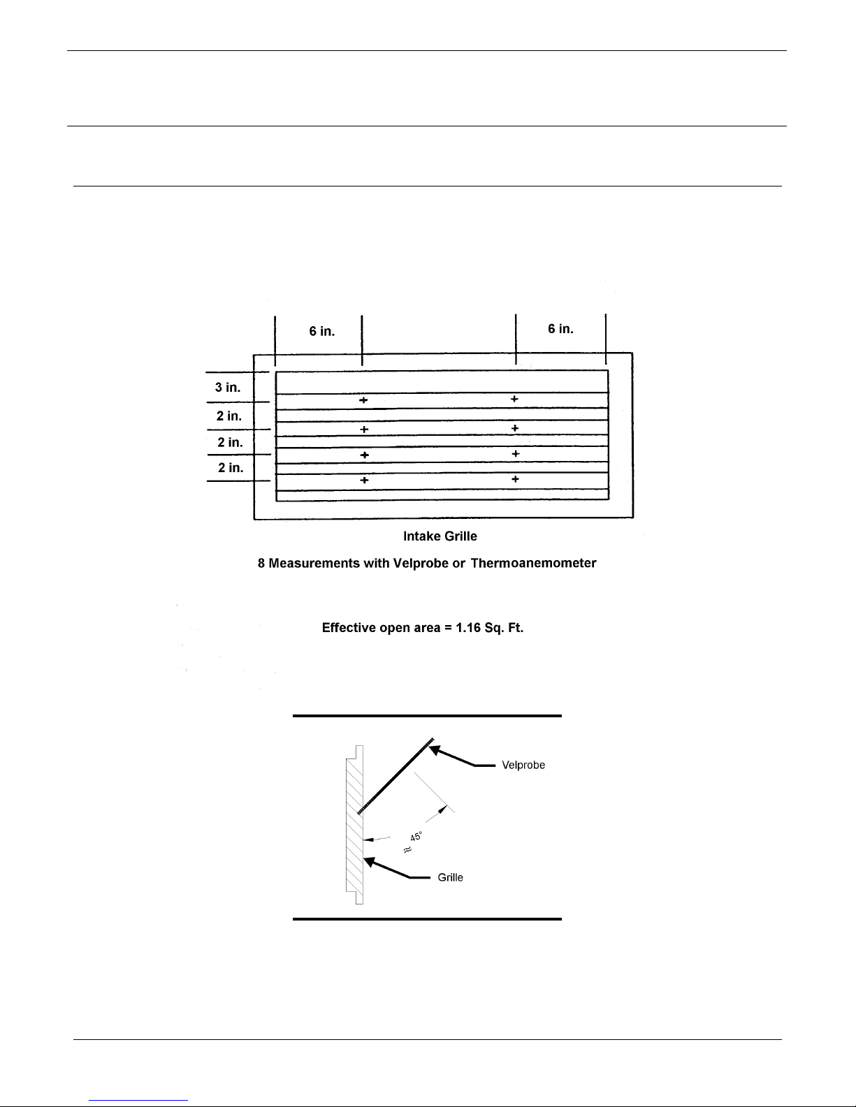
9.0. Airflow Measurement and Testing
®
and ISOCLEAN
®
UV
Page 24
Page 29
10.0. Appendix
OSPI-GARD
H
®
ISOC
LEAN
®
and ISOCLEAN
Operation Manual
APPENDIX
Room Size (Room Air Volume)
®
UV
Fan Speed
Low
(550 CFM)
Medium
(700 CFM)
High
(800 CFM)
10ftx10ftx8ft
(800 ft3)
41 ACH 28 ACH 23 ACH 20 ACH 18 ACH 13 ACH 10 ACH
51 ACH 36 ACH 28 ACH 25 ACH 23 ACH 17 ACH 12 ACH
60 ACH 41 ACH 33 ACH 29 ACH 26 ACH 20 ACH 15 ACH
12ftx12ftx8ft
(1150 ft3)
12ftx15ftx8ft
(1440 ft3)
12ftx15ftx9ft
(1620 ft3)
15ftx15ftx8ft
(1800 ft3)
15ftx20ftx8ft
(2400 ft3)
20ftx20ftx8ft
(3200 ft3)
Table 1: Representative Room Air Changes Per Hour (ACH)
Page 25
Page 30

OSPI-GARD
H
11.0. Limited Warranty
Envirco Corporation (“Envirco”) warrants the equipment will be free of defects in materials and
workmanship under normal use for a period of one (1) year. The HEPA filter shall only be
warranted against loading for a period of one (1) year when operated in clean room
conditions. Envirco’s sole obligation under this warranty is to repair or replace any parts of the
equipment which are defective for a period of one (1) year from the invoice date, provided that
the repair or replacement is actually performed within the one (1) year period from the invoice
date. The buyer agrees to assume any incidental expenses including, but not limited to, the
cost of transporting the defective equipment to Envirco’s repair facility. The buyer’s sole
remedy under this limited warranty is the repair or replacement of any defective part of the
equipment.
ENVIRCO DISCLAIMS ANY IMPLIED WARRANTIES INCLUDING WARRANTIES OF
MERCHANTABILITY AND FITNESS FOR A PARTICULAR PURPOSE. IN NO EVENT
SHALL ENVIRCO BE LIABLE FOR PUNITIVE, INCIDENTAL, OR CONSEQUENTIAL
DAMAGES ARISING OUT OF THIS SALE, INCLUDING, BUT NOT LIMITED TO DAMAGE
TO A PERSONS OR PROPERTY, LOSS OF USE, LOSS OF TIME, INCONVENIENCE,
EQUIPMENT RENTAL, LOSS OF EARNINGS OR PROFIT OR ANY OTHER COMMERCIAL
LOSS. THIS WARRANTY EXCLUDES CERTAIN EXPENDABLE ITEMS SUCH AS
PREFILTERS, ETC. ENVIRCO EXPRESSLY DISCLAIMS AND EXCLUDES FROM THE
WARRANTY ANY RESPONSIBILITY FOR EQUIPMENT FAILURES AND/OR DEFECTS
ATTRIBUTABLE TO IMPROPER MAINTENANCE, ABUSE, ACCIDENT OR
MODIFICATION OF EQUIPMENT (SUCH AS APPLICATION OF AN ADJUSTABLE
FREQUENCY DRIVE).
®
ISOC
Operation Manual
LEAN
®
and ISOCLEAN
LIMITED WARRANTY
®
UV
Page 26
 Loading...