

Page 1

www.envirco.com
ENVIRCO
Control Console
Models: CC1-10 (Part No. 63971-001)
CC1-25 (Part No. 63971-002)
CC1-50 (Part No. 63971-003)
Control Console Operation Manual Rev 0400809.doc
Operation Manual
Page 2

ENVIRCO Control Console
Operation Manual
TABLE OF CONTENTS
TITLE PAGE
1.0. SAFETY PRECAUTIONS............................................................................................................................ 3
2.0. OVERVIEW .................................................................................................................................................. 4
2.1. C
2.2. M
2.3. FEATURES......................................................................................................................................... 4
2.4. BENEFITS .......................................................................................................................................... 4
3.0. SPECIFICATIONS........................................................................................................................................ 5
3.1. E
3.2. E
4.0. INSTALLATION ........................................................................................................................................... 6
4.1. N
4.2. C
5.0. CONTROL CONSOLE OPERATION........................................................................................................... 8
5.1. FRONT PANEL FEATURES................................................................................................................... 8
5.2. P
5.3. STANDBY MONITOR MODE ................................................................................................................. 9
5.4. USER MONITOR MODE ..................................................................................................................... 10
5.5. U
5.6. OPTION MENU ................................................................................................................................. 11
5.7. ACCESS LEVELS .............................................................................................................................. 12
ONTROL CONSOLE MODELS............................................................................................................. 4
AIN FUNCTIONS............................................................................................................................... 4
LECTRICAL SPECIFICATIONS ............................................................................................................. 5
LEVATION AND DIMENSIONS ............................................................................................................. 5
ETWORK WIRING ............................................................................................................................. 6
ONTROL CONSOLE INSTALLATION TEMPLATE..................................................................................... 7
OWER ON........................................................................................................................................ 8
SER ADJUST MODE........................................................................................................................ 10
6.0. LIMITED WARRANTY ............................................................................................................................... 13
Page 2
Page 3
ENVIRCO Control Console
1.0. Safety Precautions
Please read and save the following important safety information regarding the
VOR-12 Surgery Isolator prior to unit operation.
To reduce the risk of fire, electrical shock or injury to persons, observe the following:
• Installation work and electrical wiring for the Control Console and other clean system
equipment must be done by a qualified person(s) in accordance with all applicable codes
and standards, including fire-rated construction.
• When cutting or drilling into a wall or ceiling, do not damage electrical wiring or other hidden
utilities.
• Service to the Control Console cannot be performed in the field. Returned equipment still
under warranty to Envirco.
Operation Manual
• Before trying to remove the Control Console from the clean system it controls, switch power
off for the entire clean system at service panel and lock service panel to prevent power from
being switched on accidentally, and follow proper procedures as necessary.
• Use this unit only in the manner intended by the manufacturer. If you have questions,
please contact:
ENVIRCO CORPORATION
Envirco Office
5601 Balloon Fiesta Parkway N.E.
Albuquerque, New Mexico 87113
U.S.A.
Tel : (505) 345-3561
Fax : (505) 345-8875
Email:
TRION LTD.
The Cavendish Centre
Winnall Close
Winchester, Hampshire, SO23 0LB, UK
Tel : 44 1962 840465
Fax : 44 1962 828619
Email:
info@trion.co.uk
FEDDERS INTERNATIONAL
Headquarters
No. 268 Xi Zang Road (M)
Haungpu District, Shanghai 200001
PRC
Tel : (86) 512 6258 7180
Fax : (86) 512 6258 0035
Email:
FEDDERS INTERNATIONAL, INC.
DP Computers Building
128 Joo Seng Road #05-01
Singapore 368356
Tel : 65 286 0995
Fax : 65 286 0859
Email: [email protected]
Page 3
Page 4
2.0. Overview
ENVIRCO Control Console
Operation Manual
The Envirco Control Console combines intelligent speed control with industry standard
MODBUS
®
networking. The versatile design allows control of an array of MAC 10 XL installed
Envirco Phase Controllers or “Smart” MAC 10 units linked to an Envirco DC Controller.
The console combines a user interface with MODBUS master capability so no additional
networking components are needed and no MODBUS knowledge is necessary to install a
network. Once the console has automatically scanned the network, only a few simple
configuration selections are required.
2.1. Control Console Models
Envirco CC1-Series Control Console
Model No. Addresses No. of MAC 10 XL FFUs No. of “Smart” MAC 10 Units
CC1-10 10 up to 80 up to 10
CC1-25 25 up to 200 up to 25
CC1-50 50 up to 400 up to 50
2.2. Main Functions
• Individual address speed adjustment
• Global address speed adjustment
• Global address set-back speed adjustment
2.3. Features
• 7-Seginent LED Control Console Display
• Dual rotary dials for easy option selection and system adjustments
• “Set Speed Memory” resets to last setting under power loss
• Global standby feature
• Pre-programmed user access levels and pass-codes to prevent tampering or
accidental system changes
2.4. Benefits
• Quick and easy system air balancing of Envirco Fan Filter Units
• Global standby feature for energy savings
• Simple set-up and wall-mount Control Console installation
• No installer configuration required
Page 4
Page 5
3.0. Specifications
3.1. Electrical Specifications
Supply Voltage: 6-12 Vdc
Typical Supply Current: 90 mA
Network Transceivers: 2-wire, 1/8 unit load type
Operating Temperature: 0-40° Celsius (32-104°F)
DC Power Connector: 2.1 mm DC power jack
MODBUS network: RJ45 socket
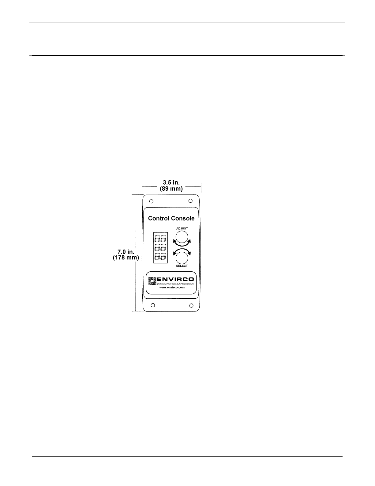
3.2. Elevation and Dimensions
ENVIRCO Control Console
Operation Manual
Page 5
Page 6
4.0. Installation
The Envirco Control Systems are engineered for easy installation. However testing either
before permanent installation or as the system is installed is strongly recommended.
The Control Console can be wall installed in the cleanroom or at a remote location, however,
the maximum recommended distance from the beginning to the end of the daisy chain should
not exceed 800 linear feet.
4.1. Network Wiring
Note: Cabling shall be provided and installed by others. Network cable requirements
A network is constructed by simply daisy-chaining MAC 10 XL installed Envirco Phase
Controllers or “Smart” MAC 10 installed DC Controllers from the Control Console.
Specific network wiring information can be found in the Envirco MAC 10 XL Control
System or MAC 10 DC Control System operation manuals.
ENVIRCO Control Console
Operation Manual
should be specified based on:
Network cable requirements should be specified based on:
• Distance between nodes
• Total network length
• Noisy electrical environment
• Environmental conditions
• Mechanical issues
Once the Control Console has been connected to at least one phase controlled MAC 10
XL or “Smart” MAC 10 installed DC Controller, power can be applied. The Control
Console will automatically scan the network.
Each Phase Controller or DC Controlled “Smart” MAC 10 FFU should be given a unique
address within the Control Console’s available address range (determined by model
number.) The addresses do not need to be contiguous, but contiguous addressing will
make operator functions easier.
Page 6
Page 7
ENVIRCO Control Console
Operation Manual
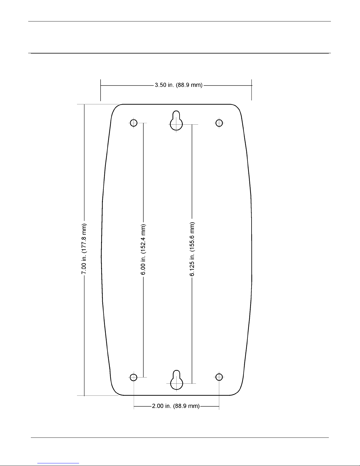
4.2. Control Console Installation Template
Page 7
Page 8
p
ENVIRCO Control Console
Operation Manual
5.0. Control Console Operation
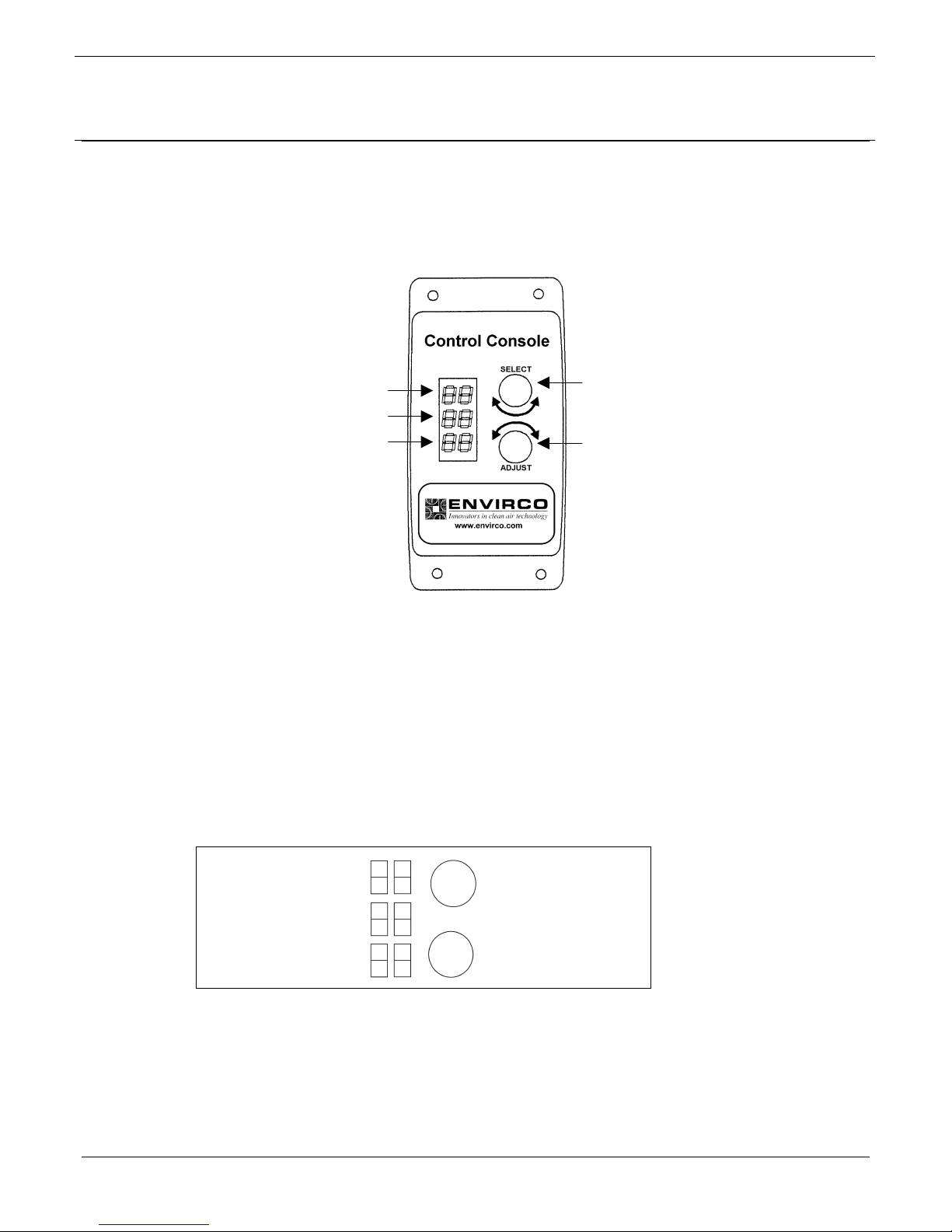
5.1. Front Panel Features
Selected Address
Status of Selected Unit
Speed of Selected Unit
• Rotate to Select Unit or
Option Menu.
• Rotate to Adjust Speed or
O
tion Settings
5.2. Power On
At power-on, the Control Console displays a series of parameters including model
number on the three LED displays for about one second. The Control Console then
cycles all segments in display to confirm that the display is functional. Once display
cycling is complete, the Control Console then scans all addresses valid for that model
(10, 25 or 50.)
If no MAC 10 XL installed Envirco Phase Controllers or “Smart” MAC 10 units linked to
an Envirco DC Controller is detected, the Control Console repeats the scan sequence
until at least one unit is found.
Scan Address
Number of Units found
No Effect
No Effect
Figure 1: Front Panel Functions During Power-On
Page 8
Page 9
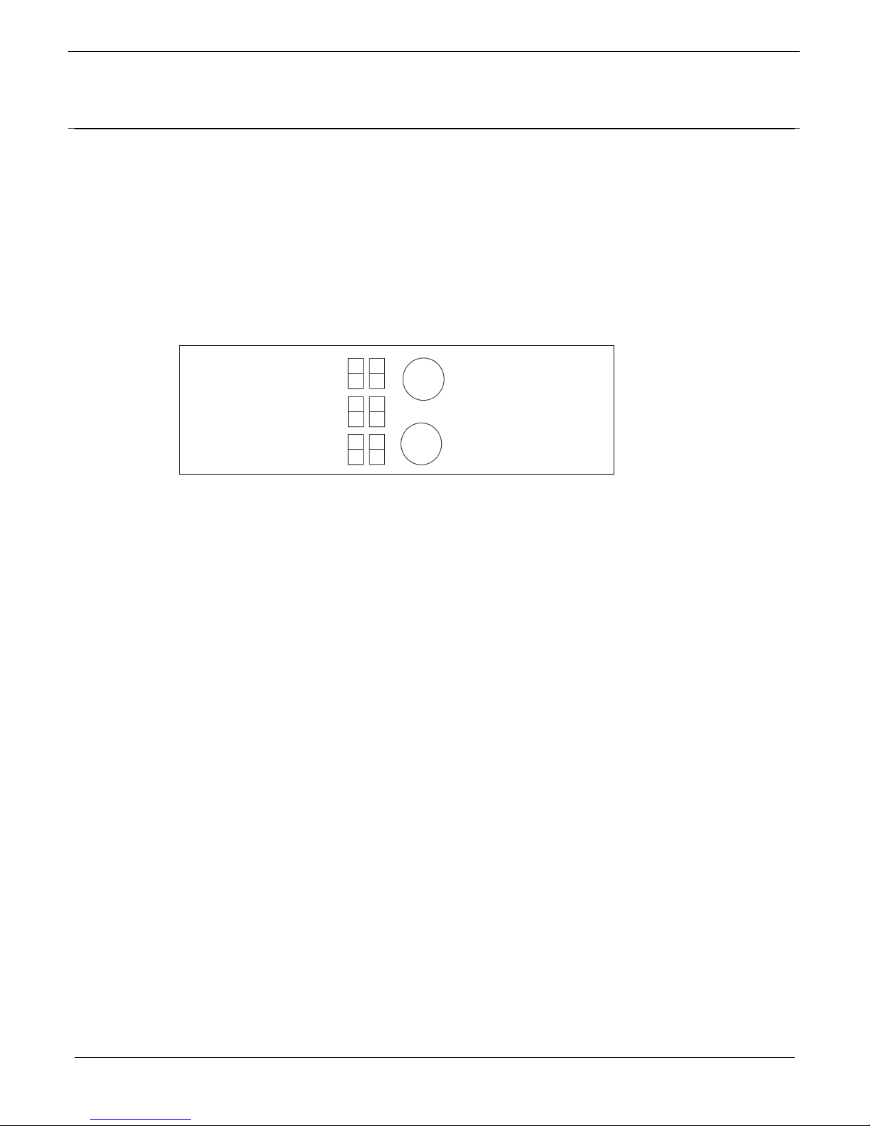
5.3. Standby Monitor Mode
The Control Console immediately enters standby monitor mode at the conclusion of
power-on scanning. The Control Console remains in standby monitor mode until one of
the two dials are rotated. If the dials are not adjusted for a period of 30 seconds, the
Control Console will revert to standby monitor mode.
In standby monitor mode, the Control Console repeatedly polls all units detected during
power-on scanning. Unused motor addresses are skipped, but the highest address
must be within range of the Control Console model settings (10, 25 or 50.)
ENVIRCO Control Console
Operation Manual
Address
Pressure Switch Status
Set Speed
Any rotation to exit standby
monitor mode
Figure 2: Standby Monitor Mode Front Panel Functions
The Control Console polls each Phase Controller or “Smart” MAC 10 FFU while
displaying status information on each unit for about 2 seconds. The following
information is displayed:
A. MODBUS Address of unit monitored (Top LED)
B. Pressure Switch Status
• “PG” for Pressure Good
• “PF” for Pressure Fault
• If Pressure Switches are not enabled, the display will be blank
• If the Control Console is in Low Speed Mode, then “LO” will be displayed instead
of the pressure switch status
C. Set Speed or Blank Display (Center LED)
• Displays Set speed in percent
• This value is read from MODBUS register 2.
Note: If no response is received, the middle and lower LED shall display “—“
Page 9
Page 10
ENVIRCO Control Console
Operation Manual
5.4. User Monitor Mode
If any dial activity is detected, the Control Console leaves standby monitor mode and
enters user monitor mode. In this mode, any unit can be selected by rotating the Select
dial.
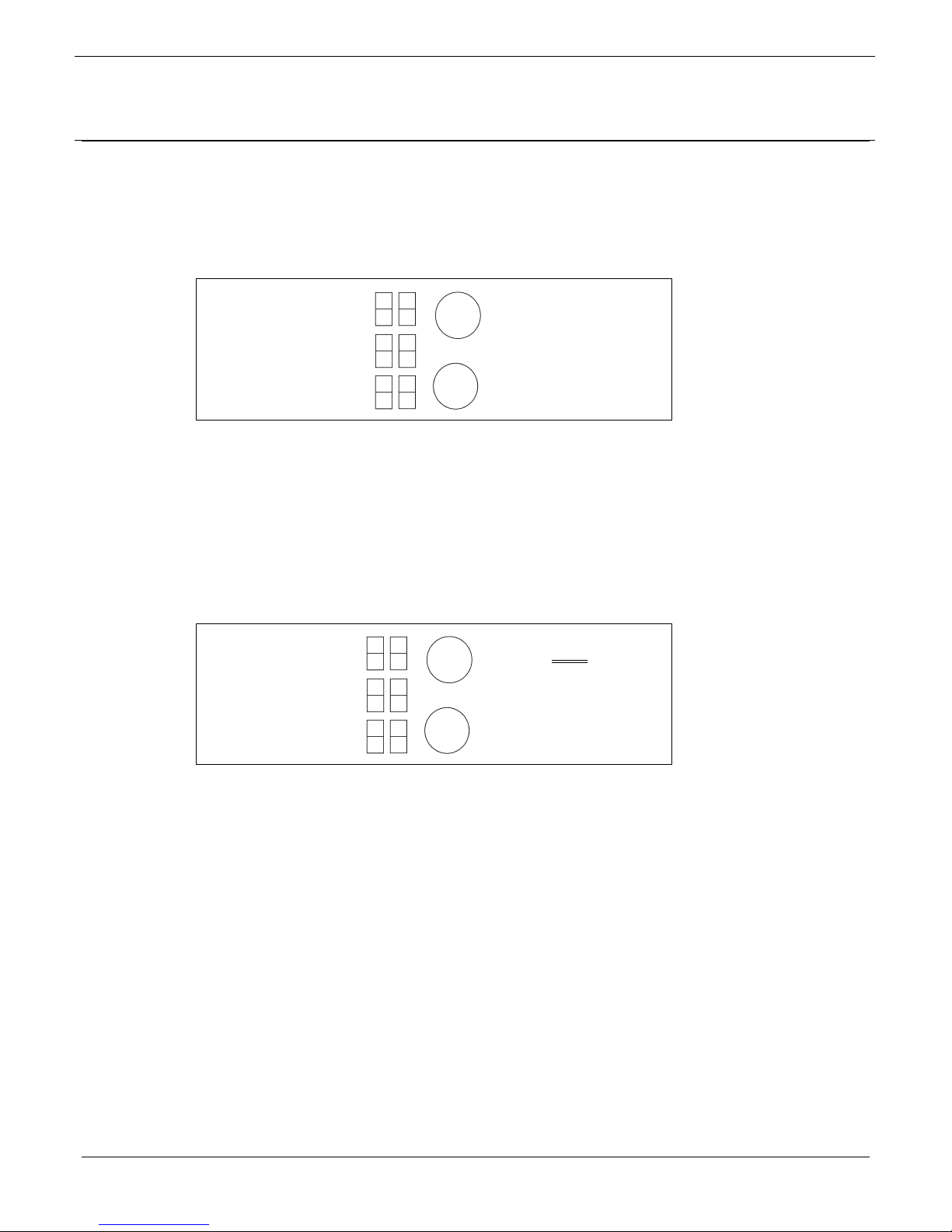
Address
Pressure Switch Status
Set Speed
Rotate to select address.
Press to lock selection.
No Effect
Figure 3: User Monitor Mode Front Panel Functions
Note: If the Select dial is moved past the valid address range, the select display shows
"OP". Pushing the Select dial enters the Option Menu.
5.5. User Adjust Mode
This mode is identical to User Monitor mode, except that the set speed of any motor can
be adjusted.
Address
Pressure Switch Status
Set Speed
1. Rotate to select
2. Adjust Set Speed
Up or Down.
address.
Figure 4: User Adjust Mode Front Panel Functions
If the Select dial is moved below the valid address range, the select display shows "OP".
The current access level is also displayed. Pushing the Select dial enters the Option
Menu.
The Control Console writes the set speed as a percentage of the maximum speed (099%). If power fails, each Digital Speed Controller will run at the most recent speed
selected.
Page 10
Page 11
ENVIRCO Control Console
Operation Manual
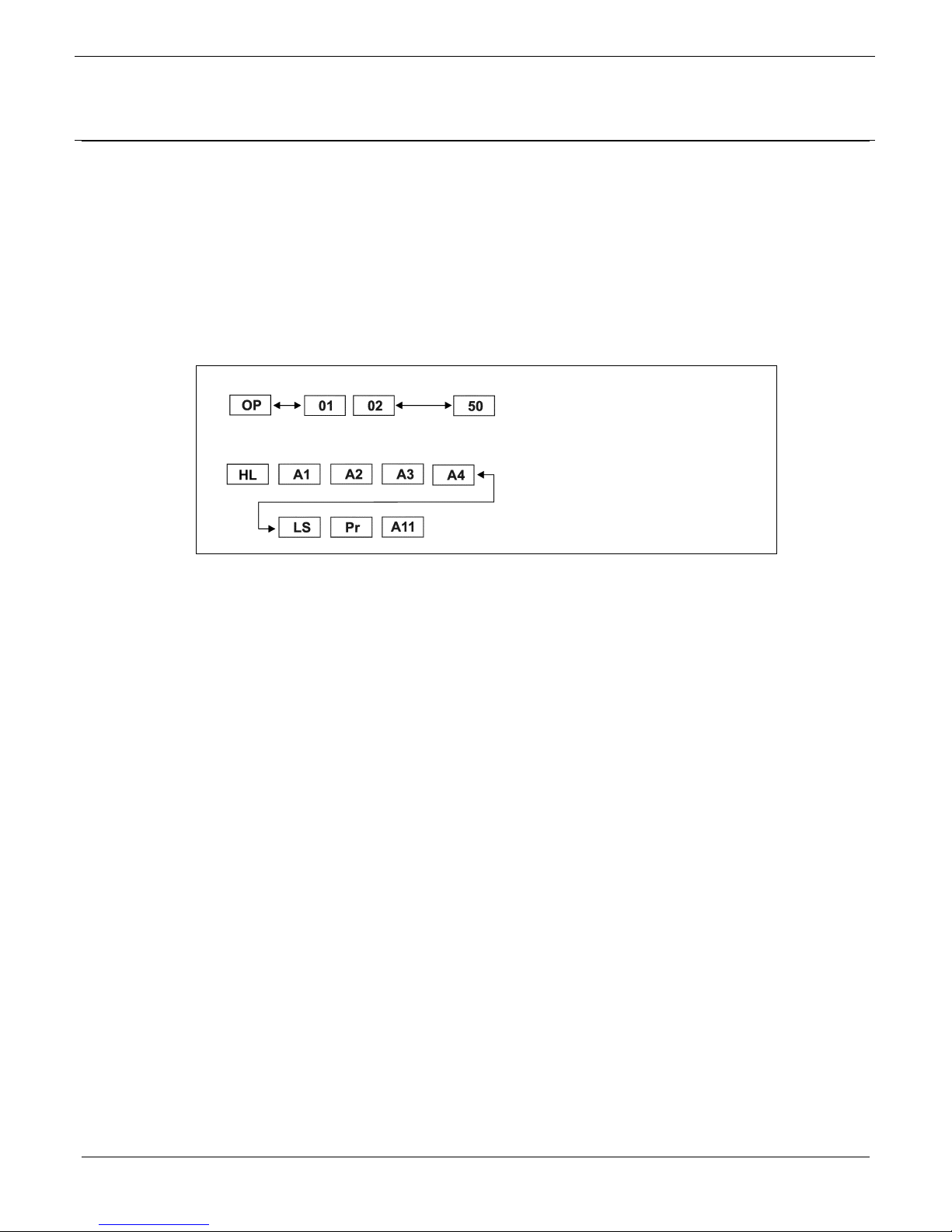
5.6. Option Menu
The option menu allows a user to perform the following functions:
A. Change the access level by entering pass-codes (A1…A3)
B. Select High Speed (normal) or Low Speed (global set back)
C. Adjust the Low Speed set back
D. Select whether pressure switches are present or not
E. Set the speed for every node simultaneously
1. Rotate Select di al to display
“OP” on top LED.
2. Press Select dial to enter option
menu.
1. Rotate Select di al to display
desired option in the center LED.
2. Push Select d ial again to exit
option menu.
Figure 5: Option Menu Navigation
5.6.1. Access Levels
• Use the Select Dial to display the new access level requested.
• Press the Select Dial
• If the new level has fewer privileges, then no pass-code is needed. The
bottom LED will scroll through its seven LED segments to confirm the change
• If a pass-code is needed, enter the two-number code on the Adjust Dial.
Press the Adjust Dial to lock in the code.
• If the pass-code is correct, the bottom LED will scroll through its seven LED
segments
5.6.2. Selecting High or Low Speed (HL)
• This action requires access levels A1-A3
• Rotate the Select dial to display “HL” in the center LED and press Select dial
to lock in this option.
• Rotate the Adjust dial to select "HI" or "'LO"
• If “HI” is selected the units shall run at their individually set speeds
• If “LO” is selected, each unit will be set back by a global amount (see
adjusting Low Speed below)
• If Low Speed is selected, this setting will remain in effect until High Speed is
selected or the power is cycled.
Page 11
Page 12
ENVIRCO Control Console
Operation Manual
5.6.3. Adjusting Low Speed Set Back (LS)
• This action requires access levels A1-A2
• Use the Select dial to display the “LS” menu option
• Rotate the Adjust dial to vary the set-back percentage (0-99%)
5.6.4. Selecting Pressure Switch (Pr)
• The Pressure switch option should be enabled if Phase Controlled units have
a pressure switch installed
• Rotate the Adjust dial to select:
A. “NC”: Normally closed (the switch opens if there is a pressure fault.)
B. “NO”: Normally open (the switch closes if there is a pressure fault.)
C. “__”: No pressure switch
5.6.5. Global Speed Set (All)
• This is available only when operating at Access Level 1.
• Rotate the Adjust dial to set the desired speed.
• Press the Adjust dial to set every node to that speed
5.7. Access Levels
To restrict access to functions other than monitoring, the Control Console implements
access levels. Level A1 carries the greatest privileges.
Access Level Pass-Code Description
A1 12 88 Operator can adjust configuration settings.
A2 25 75 Operator can use all functions for monitoring and control.
A3 49 51 Operator can monitor and adjust High/Low settings.
A4 N/A Operator can only monitor status of the network.
Table 1: Access Levels and Codes
Page 12
Page 13

ENVIRCO Control Console
Operation Manual
6.0. Limited Warranty
Envirco Corporation (“Envirco”) warrants the equipment will be free of defects in materials and
workmanship under normal use for a period of one (1) year. The HEPA filter shall only be
warranted against loading for a period of one (1) year when operated in clean room conditions.
Envirco’s sole obligation under this warranty is to repair or replace any parts of the equipment
which are defective for a period of one (1) year from the invoice date, provided that the repair or
replacement is actually performed within the one (1) year period from the invoice date. The
buyer agrees to assume any incidental expenses including, but not limited to, the cost of
transporting the defective equipment to Envirco’s repair facility. The buyer’s sole remedy under
this limited warranty is the repair or replacement of any defective part of the equipment.
ENVIRCO DISCLAIMS ANY IMPLIED WARRANTIES INCLUDING WARRANTIES OF
MERCHANTABILITY AND FITNESS FOR A PARTICULAR PURPOSE. IN NO EVENT
SHALL ENVIRCO BE LIABLE FOR PUNITIVE, INCIDENTAL, OR CONSEQUENTIAL
DAMAGES ARISING OUT OF THIS SALE, INCLUDING, BUT NOT LIMITED TO DAMAGE
TO A PERSONS OR PROPERTY, LOSS OF USE, LOSS OF TIME, INCONVENIENCE,
EQUIPMENT RENTAL, LOSS OF EARNINGS OR PROFIT OR ANY OTHER COMMERCIAL
LOSS. THIS WARRANTY EXCLUDES CERTAIN EXPENDABLE ITEMS SUCH AS
PREFILTERS, ETC. ENVIRCO EXPRESSLY DISCLAIMS AND EXCLUDES FROM THE
WARRANTY ANY RESPONSIBILITY FOR EQUIPMENT FAILURES AND/OR DEFECTS
ATTRIBUTABLE TO IMPROPER MAINTENANCE, ABUSE, ACCIDENT OR MODIFICATION
OF EQUIPMENT (SUCH AS APPLICATION OF AN ADJUSTABLE FREQUENCY DRIVE).
Page 13
Page 14
5601 Balloon Fiesta Parkway N.E. • Albuquerque • New Mexico • 87113 • USA
505.345.3561 • 800.545.6598 • Fax: 505.345.8875
www.envirco.com
 Loading...