

Page 1
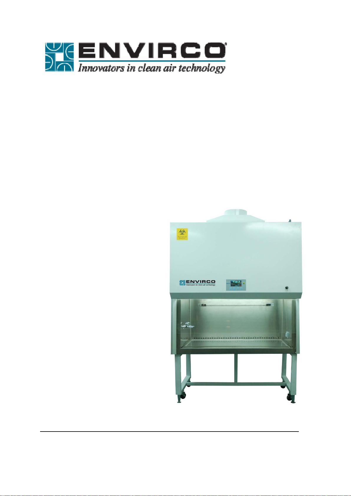
Biological Safety Cabinet
4
’
Model Number 11228-001
User Manual
Envirco 101 McNeill Rd. Sanford, NC 27330 Phone: 1-800-884-8002 Fax: 1-800-458-2379
Page 2

Catalog
I、Introduction 4
1.1 Specifications 5
II、Inst
allation 6
2.1 Position 6
2.2 Disassembly and handling 6
2.3 Assembly and installation 6
2.4 Check?? 7
III、Adjustment
s and testing 9
3.1 Adjustments on site 9
3.2 Tests and standards 9
3.2.1 Filter leakage test 9
3.2.2 Air adjustment of opening of work area 9
3.2.3 Downflow air velocity 10
3.2.4 Pressure test 10
3.3 Sterilization 10
IV、USE AND
MAINTENANCE 15
4.1 General operatingguidelines 12
4.1.1 Description: 12
4.1.2 Typical uses 12
4.1.3 Air filter system 12
4.1.4 Use instructions 12
4.1.5 Digital control circuit 13
4.1.6 Differential pressure indicator 14
4.1.7 Use of UV light 14
4.1.8 Use of electrical outlet 15
4.2 General maintenance 15
4.2.1 Running 15
4.2.2 Construction materials maintenance 15
4.2.3 Wipe down flows 16
4.2.4 Base plenum 16
4.2.5 Visual inspection 16
V、SER
VICE AND COMPONENTS 20
5.1 Main components replacement 16
5.1.1 Replacement of HEPA filter 17
5.1.2 Removal of filter 17
5.1.3 Filter installation 17
5.1.4 Motor replacement 21
2
Page 3

5.2 Pressure monitor calibration 18
5.3 Major parts list 23
5.4 Fault finding hints 19
5.5 Attention to maintenance 21
VI、Inst
allations requiring connection to external exhaust systemError! Bookmark not defined.
6.1 Canopy/thimble connection 25
6.2 Hard connection 25
6.3 IFlow alarm monitoring system instructions 26
VII 、Label instructions 27
APPENDIX 1 Error! Book
DOWNFLOW/HAND INTAKE SETTINGS Error! Book
BIOHAZARD CABINETS-Class Error! Book
mark not defined.
mark not defined.
mark not defined.
FIGURE1 BASE FRAME ASSEMBLY 27
FIGURE 2 BOTH SIDE PANELS
_Toc265052624
FIGURE 4 MAIN PARTS Error! Book
mark not defined.
FIGURE 5 CONTROL PANEL 30
FIGURE 6 MEASUREMENT OF BIOHAZARD CABINET 28
FIGURE 7: AIR FLOW PATTERN AND PROTECTED AREA 30
FIGURE 8: FRONT ACCESS PANEL REMOVAL 30
FIGURE 9: GLASS CLIP 32
FIGURE 10: PRESSURE MONITOR CALIBRATION SETUP Error! Book
FIGURE 11: EXHAUST SYSTEM Error! Book
mark not defined.
mark not defined.
FIGURE 12: ELECTRICAL SCHEMATIC 33
VIII 、W
arranty
3
Page 4

I、Introduction
Investigators and technicians concerned with microbiological safety have, for many years,
utilized specialized containment enclosures to limit their exposure to harmful pathogens. In
addition, it is recognized that exacting research, as well as routine pathology, is often
compromised by environmental contamination. The ENVIRCO Class II Biohazard Cabinet is
designed to limit the contamination exposure of both the worker and the work when handling
biohazard material. The Class II enclosure is an open-face cabinet with a high volume of air
circulated through an internal HEPA filter. Air is drawn into the open front of the cabinet and
exhausted through a HEPA filter. The controlled airflow direction and volume balance provide
protection for the worker, the work (sample), and against cross-contamination within the
cabinet.
This product has been tested to meet the requirements of CAN/CSA-C22.2 No.61010-1,
secondedition, including Amendment 1,or a later version of the same standard incorporating
the same level of testing requirements.
Important
Volatile, friable or poisonousradioactive substancesarenot allowed in the
non-exhaust-cover cabinet.
Sterilize the cabinet before turning off PAO test switch or wash water valve
Do not hinder airflow flowing out of HEPA filter.
Disconnect power before accessingthe operational board.
Maximum power of this equipment is 1000W.
Connect Only To Properly Grounded Outlet. Do Not Remove Ground Pin.
If the equipment is used in a manner not specified by the manufacturer, the
protection provided by the equipment may be impaired.
If needed, please use the emergency power cut-off, located on the front panel.
4
Page 5

Technical Specifications
Model: 11228 -001
Nominal Size: 4Ft.(1.2 meters)
Internal Dimensions: (WxDxH): 55.9″x 33.4″x 85
Internal Size: (W x D x H): 48″x 26.1″x25.6″ (1220 x 665 x 65
.8″ (1421 x 850 x 2180mm)
0 mm)
Average Airflow Velocity:
o Inflow:105fpm (0.53±0.015m/s)
o Downflow:66fpm (0.33±0.015m/s)
Airflow Volume:
o Inflow: 275cfm (465m³/h)
o Downflow67%: 571cfm (956 m³/h)
Exhaust, 33%: 275cfm (465 m³/h)
HEPA filter efficiency: >99.99% for particle size above 0.3 microns
Both filters are HEPA filters, H14.
Supply filter 1: 99.998% MPPS, Exhaust filter: 99.996%@ MPPS
Supply Filter 2: 99.998%MPPS, Exhaust filter : 99.996%@MPPS
Both filters are HEPA filters, H14.
Noise: ≤ 67dB(A)
Fluorescent lamp intensity: ≥650Lu
x
Ground resistance: ≤ 0.10Ω
Voltage Resistance: 2 seconds no breakdown with DC1200V
Cabinet Construction: Work area: 1.5mmstainless steel
Frame: cold-roll steel sheets with electrostatic coating
Working Environment: Use indoors only
Environmental temperature: 59°F– 95°F (15Ԩ-35Ԩ)
Relative humidity: ≤75
%;
Range of atmospheric pressure: 70kPa~106kPa
5
Page 6

Power supply: AC 120V±10%, 60Hz ±1Hz
Serial number is on cabinet; see operational board mark.
II、Installation
2.1Position
The Biological safety cabinet should be positioned in an airflow-protected zone in order to
prevent the airflow from being adversely affected. This can be caused by ventilation
systems,air-conditioning or personnel movement.If the test shows that the interference of
other airflow overpasses the inlet speed into cabinet air flow, indoor infectious gas can enter
the biological safety cabinet work area. Therefore, it is necessary that the cabinet be
positioned correctly.The relationship between the safety cabinet exhaust air and indoor air
exhaust ventilation pipes should also be notedso that the air emission exhaustsfrom the top of
the cabinetand the cabinet itselfshould be positioned to avoid restrictions from its
exhaust.Biological safety cabinets should be in the downstream airflow direction;if possible,
the best way to install this cabinet is to reserve a 12” clearance on all four sides of the cabinet.
Pay special attention to the electrical line: every biological safety cabinet must adopt its
own exclusive line directly into the socket. Do not, under any circumstances, allow the use of
an extension cord without permission from the manufacturer to modify the powercord.
This biological safety cabinet can operate 24 hours a daysuccessively. All circuits and motors
are adequate and have protection measures.
2.2 Disassembly and handling
When the equipment is received,please check the box for outside damage conditions. Broken
glass or other damage should be notedupon receipt of equipment andcarrier should be
notified immediately.
1) If you do not receive return authorization, the equipment cannot be returned to the factory.
2) If the equipment is in cold weather transportation, it should be placed near the desired
location and left at room temperature for 24 hours prior toassembly.
3) First, remove all surface protection material. Read Item #7 below. Do not try to lift the
packageunder frame before the device is completely exposed.
4) When removing the packaging materials, carefully put assembly parts to one side. Excess
packaging tape residue can be wiped clean with alcohol.
5) Check all parts in the transport making sure there are no damaged parts. If damaged parts
are found, immediately report them to the transportation company. If there is damage, do not
open the packaging;the consigner may be asked to inspect the box.
6) Lift the Equipment off the packageunder frame and release the four stop blocks.
7) The security cabinet is very heavy and is equipped with highly efficient HEPA filters that
should be moved carefully. The safety cabinet should be transferred by a vehiclesuch as a
fork lift.
8) The cabinet should not be upside down during shipment under any circumstances.If so
contact the carrier
6
Page 7

2.3 Assembly and install
1) Assemble the under-frame, see installation Figure 1.
FIGURE 1: BASE FRAME ASSEMBLY
1. Seven M10×50 bolts
2. Horizontal support without hole is fastened with two M10×50 bolts
3. Horizontal support with hole is fastened with two M10×50 bolts
4. Left-side support
5. T-style support is fastened with three M10×50 bolts
6. Right-side support
7
Page 8
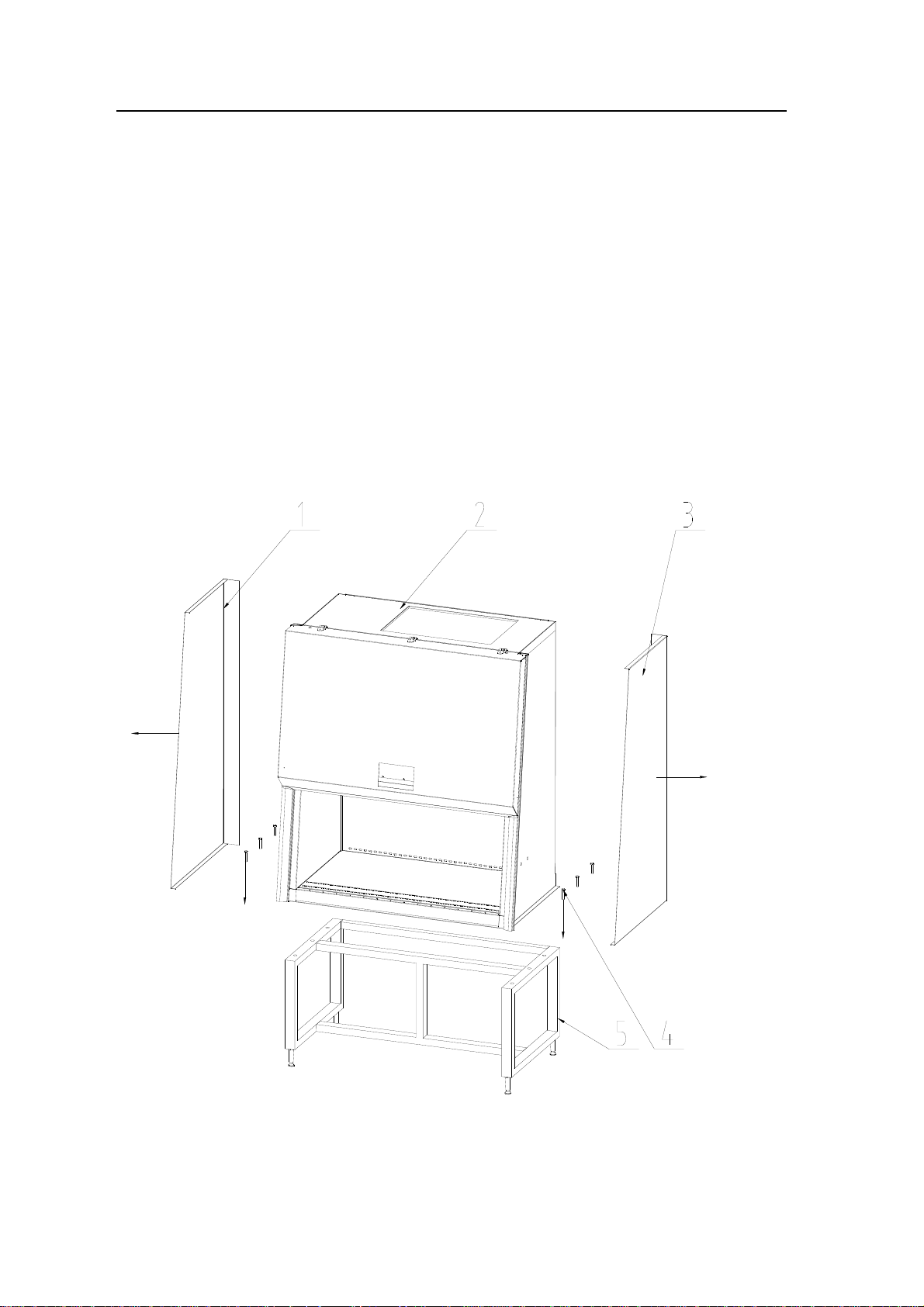
2) Unload the two side panels see Figure 2.
3) Place cabinet onto under-frame and secure with bolts. Bolts are in the cabinet work zone
bag.Make the connection between the under frame and cabinet body (sees Figure 3), and
then mount side panels;
FIGURE 3: CONNECTION OF BASE AND CABINET BODY
1. RIGHT PANEL
2. CABINET
BODY
8
Page 9

3. LEFT PANEL
4. M10 BOLT
5. BASE FRAME
4) Adjust under-frame and level the working surface to ensure the maximum stability on floor.
5) Remove the internal packing materials, empty all parts and clean all debris from inside of
the cabinet
Note: Any residual debris may lead to damage to the HEPA filters and fan.
6) Check packing list to ensure that all materials and accessories are included.
7) Check the internal and external safety cabinet carefully and inspect all components that
may have loosened during transport. If necessary, check for filter leakage. Check the front
panel fixed bolts; the bolts should not be too tight. If you need to check the air filter surface,
you can release the fixed wing nut bolt, remove from the front of the wing nut and then
carefully inspect.
8) Check to make sure the work surface is firmly installed.
9) If the safety cabinet is equipped with water and air, connection to building or other services
must be in accordance with local codes.
10) Install the exhaust HEPA protection device on the exhaust filter: The protection device will
be placed around the filter opening, fixed with a nut.
NOTE: Do not, underany circumstances, put hand into exhaust filter.
11) Remove the four screws and lift out work surface panel. Remove the plug on the
down-board;secure the valve connecting the pieces to the down-board, connecting the drain
valve and making sure valve is in a closed drain position, (parallel to the ground).
12) The device is equipped with a HEPA exhaust protection device on the top. If the
equipment request is to connect to the external exhaust system (used in toxic, poisonous gas
or steam), be sure to refer to Chapter 6 of the external exhaust systems.
NOTE: The minimum distance between exhaust HEPA filter and the ceiling is 11.8”
(300mm). If the exhaust HEPA filter is blocked, sufficient air will not flow into the outlet
operating area. The inlet operating the open airflow speed should be checked on
location, when the exhaust HEPA filter is at the top of the clean room, less than 15.9”
(406mm).
13) Install ultraviolet and fluorescent lamp.
14) Installation of the main components, see Figure 4.
9
Page 10

FIGURE 4: MAIN PARTS
1. Exhaust filter protector hood
2. Operational board
3. UV light
4. Control panel
5. Light
6. Power lock
7. Base frame
8. Emergency stop
10
Page 11

2.4 Check
1) Connect the biological safety cabinet’s dedicated power line to power outlet on a 120V
power source, with a total power of 20 amps. The biological safety cabinet must be the only
equipment on the circuit; see the electrical equipment requirements data on the cover.
2) Turn the key on the front panel and press the power button located on the control panel.
There will be a delay on the fan in order to achieve the required speed. In order to prevent too
much current, the fan needs a delay of about 10-15 seconds in order to achieve full speed
before motor is running. Similarly, the fan also needsa 10-15 second delay to stop. Stable
voltage is provided by a built-in voltage regulator circuit for the motor/blower which helps to
eliminate air fluctuations. Please remember to turn fan of before shutting down.
3) Press the LIGHT button on control panel to turn on the lights. If the lamp is not bright, check
the lamptube or socket. It may have come loose between the lamp and lamp holder during
shipping.
4) Press the UV button on the control panel, turn on the UV lamp and check to make sure the
UV light is working properly.
NOTE: For safety purpose the UV lights will only operate when the glass dooris fully
closed.
5) Press key SOCKET button on the control panel and check the safety cabinet's internal
power socket. If the safety cabinet is equipped with two sockets, this button will control both.
11
Page 12

III. Adjustments and Testing
3.1 Adjust on site
Before packing and transport, this safety cabinet has been tested and confirmed in our
factory; however, another test after installation must be performed. Only qualified personnel
can adjust this device and in order to ensure the accuracy of the on-site testing, this test
equipment must be calibrated. If you cannot implement this operation, please contact
ENVIRCO to provide a local on-site testing services company.
On site adjustment should include the following
- Check the safety cabinet inflow
- Check the safety cabinet internal decline airflow rate
- Check airflow inside the cabinet by using smoke simulator
- When the cabinet is connected to the building’s exhaust system, balance the air emission.
Toensure that your new equipment is accurate, perform an on-site inspection. The equipment
cannot be used without this pre-test, performed by qualified personnel.
Do not adjust the fan speed without fully testing decline of the wind speed and the inflow air.
The manufacturer has already set the correct air flow; no further adjustments should be
required. Do not change the valve set of the ratio between the exhaust and air supply unless a
qualified person thinks it is necessary to do.
3.2 Tests and standards
3.2.1 Filter leakage test
The standard aerosol testing for the integrity of the HEPA filtersis generally performed
annually. Qualified personnel must use a calibrated device when aerosol testing. A
referenced list will be provided by the factory.
:
NOTE: Place connection between supplyair and exhaust filters hose test for pressure
(the middle hose) photometer upper (PAO test point connection).
3.2.2 Air adjustment at the opening of the work area
The exhaust HEPA filter should be installed on the top of the biosafety cabinet. The air volume
exhausted is equal to the air volume entering from the work area opening. The average
velocity entering the opening of the work area has been identified during the design of the bio
safety cabinet. The test should conform to the rules of NSF49. The opening air velocity testing
data is in APPENDIX 1. To adjust the fan speed, adjustments should be according to the data
specified in APPENDIX 1.
12
Page 13

APPENDIX 1
DOWNFLOW/HAND INTAKE SETTINGS
BIOHAZARD CABINETS-Class II
INFLOW MEASUREMENT USING THE THERMOANEMOMETER METHOD
CALCULATED
HIGHEST READING
CABINET
MODEL
HAND INTAKE
DOWNFLOW
AND LOWEST
TYPE
11228 BBC 86 A2
VELOCITY
0.505-0.555m/s
0.305 - 0.355m/s
READING
±20% OF AVERAGE
To set the air velocity of the opening work area correctly, we emphasize again that only
qualified persons using calibrated equipment may carry out the adjustments. If you have
difficulties, please contact the manufacturer.
NOTE: Adjustments must be made in conjunction with the down flow air velocity
profiling section and it is necessary to have a balance test between them.
3.2.3 Downflow air velocity
The equipment’s airflow should be balanced and generally the only requirementis outlined in
Section 3.2. However, as the HEPA filter becomes loaded, the readings on the static pressure
monitor will increase (located on the control panel). The fan speed needs to adjust so it can
build up to the correct air velocity within the working chamber. The equipment is designed with
an air damper. We can control the exhaust and inflow air ratio by adjusting the positions of the
damper. The setting is done in the factory and generally needs no adjustment. The
equipment’s correct settings and the testing data are in feet per Minute (FPM)
NOTE: Adjustments to the balance of the air velocity should be made by a certified
Technician.
3.2.4 Pressure test:
When testing pressure, the PAO test port can be used to introduce the pressurizing gas
(generally air).
3.3 Sterilization:
Before sterilizing the equipment, do not remove the front grids or the drainage valve.
You must sterilize the equipment per the following:
-------Before operation
-------Before replacement of the filter
-------Before performance testing (unless the equipment is new and has never been used)
-------Before moving the equipment
13
Page 14

-------Prior to initiating a totally different work procedure
-------When the safety office or safety committee requested
NOTE: Only the safety office and the safety committee can determine the correct
sterilization procedure.
For the convenience of the vapor sterilization, the following cabinet size is available (see chart
7):
(Chart 7)
MODEL OVERALL SIZE WORKING AREA SIZE Weight
L x W x H
Inch (mm)
11228-001 55.59 x 33.46 x 85.82
(1412 X 850 X 2180)
L x W x H
Inch (mm)
85.82 x 26.18 x 25.59
(1220X665X650)
Lbs (Kg)
838
(380)
TESTING AND CERTIFICATION
The ENVIRCO Biohazard Cabinet has been fully tested by the manufacturer prior to
shipment; however, shipping and handling during installation may result in leaks in the HEPA
filter or other cabinet seals. The cabinet should be adjusted for proper airflow balance after it
has been installed in the final location.
Recommended Tests
The following tests are recommended at initial installation:
1. Aerosol Leak Test of the recirculating air HEPA filters
2. Aerosol Leak Test of the exhaust air HEPA filter
3. Adjustment of the airflow within the cabinet to an average velocity per values on page 10 of
this manual
4. Adjustment of the exhaust air volume to provide a minimum inward airflow per values on
page 10.
5. Visually verify that an inward airflow exists around the entire periphery of the face opening
using an acceptable smoke challenge
6. Check electrical continuity between cap plug ground pin and exposed metal cabinet
surfaces to verify that electrical resistance does not exceed 0.15 ohms. Initial on-site testing
and certification of the ENVIRCO Biohazard Cabinet is included with the purchase of the unit.
Contact an AuthorizedService Contractor to arrange for certification date. Testing and
certification service includes operation and maintenance training for the unit and validation of
the manufacturer’s warranty. Operation of the cabinet prior to authorized certification may
void the warranty and service contract or result inadditional service contractor charges.
Authorized Service Contractor:
ENV Services, Inc. (800) 345-6094Service Record
14
Page 15

A service record card is permanently attached to the front of the cabinet. An Authorized
Service Contractor will record service functions and validate the card upon completion of
certification.
IV、USE AND MAINTENANCE
4.1 General operation rules
4.1.1 Description:
The Biosafety Cabinet should conform to the standard of the American
NSF/ANS149-2004and A/B3, an earlier edition.
The equipment provides the following three functions:
1. Effective protection for personnel from particulate or aerosol airborne contamination
generated within the work chamber
2. Provide clean working zone in the work chamber. The laboratory airborne
contamination cannot impinge on the work surface.
3. The analyte on the two sides has no cross-contamination
4.1.2 Typical uses
The Biosafety Cabinet is generally designed to provide a clean working environment for the
laboratory.
The equipment can protect the operator and prevent cross-contamination. It is used in
production areas and the following work.
Low and moderate risk biological agents*
Pollens, allergens, etc.
*The Class II BiosafetyCabinet’s risk level is defined by the US Standard
ANSI/NSF 49:2002 and references the following:
(1)The risk levels Class 1,2,3,4 are classified by the HEALTH, EDUCATION and WELFARE
CENTER for disease control.
(2)The International Cancer Defending Organization defined the oncogenic viruses as
moderate risk.
(3)Laboratory biosafety brochure
The operator can obtain the satisfied results only after becoming fully acquainted with the
correct operation process.
15
Page 16

4.1.3 The air filter system
Figure 7 is the equipment’s air flow pattern and the protection zone. The air filter system is the
main system to guarantee the equipment’s performance. It consists of a blower, wind pipe,
supply filter and exhaust filter.
The air filter system’s main function is to produce clean air for the work zone. The average
vertical down flow velocity of the clean air in the work zone can reach 0.33fpm +-0.015m/s,
while cleaning the exhausted air and preventing environmental pollution.
4.1.4 Use instructions
(a)The equipment is designed for continuous work, but in order to prolong the HEPA filter’s
life, it is recommended opening it only when necessary. Run the equipment with electrical
power several minutes to ensure the air flow remains steady inside the cabinet.If the cabinet
has deposits in the contamination area, there should be no operation.The front panel should
remain closed to keep the work zone area safe until work area has been properly cleaned.
(b) Use a proper disinfectant to clean the internal work zone before operation.
(c) Examine the pressure readings; when the fan motor is open, you can feel the air flow
across the front window.
(d) When the glass door is open, the ultraviolet lights will not operate.
(e) Inspect the drainage valve and put it into the closed position.
(f) Arrange your experiment and work flow. Don’t mix the work zone with unnecessary items.
(g) Test results have indicated that the protection of the?? safety cabinet is excellent over
extended periods of time.
(h) When a dispensing operation is being carried out within the cabinet, samples should be
moved for storage to the right or left side of the dispensing operation. If the correct techniques
are exercised, there will be no cross-contamination within the cabinet.
(i) Remember the operator’s arms and hands will be the primary source of contamination and
particulates, so one must use sterilized gloves and soap to clean hands and arms.
(j) When the outside air and the adjoining work area are seriously polluted, the operator
should take the proper measures to prevent the particulates from entering the clean work
area.
(k) The air return grills at the front and rear of the work area must never be blocked, especially
when sterile drapes are being used.
16
Page 17

4.1.5 Digital control circuit
(a) The EnvircoBiosafety Cabinet has utilized the latest microprocessor control technology to
control and inspect the Biosafety’s Cabinet’s function. It is simple to operate and is user
friendly while providing a high degree of reliability for diagnostic functions.
(b) Connect the cabinet to the recommended electrical outlet.
(c) Turnthe keyclockwise to power the equipment. The display will illuminate, then go dark and
repeat three times. At the same time, a buzzer will sound off three times.
(d) When you power on, the unit will automatically start a self-check to test its integrity and
safety performance. When the front panel is too high, it will alarm and at the same time the NO
SAFETY on the Vertical Front Display (VFD) will light. At that time, it will be OKAY to adjust
the height of the front panel. If the supply and exhaust filter cannot reach the specified setting,
the equipment will emit an audible-optic alarm. It will notify the user to replace the filter to
protect the user’s safety.
(e) After the unit performs its self-inspection, the equipment will go into a standby mode and
wait for the operator to press the keypad for the desired operation.
(f) After pressing the power button, the default display for supply air differential pressure will
be zero.
(g)The fan motor can be activated by the switch on the control panel. The fan motor mark on
the VFD will light and the motor will start up slowly. It will reach a normal operation speed in
10-15 seconds.
(h) When the stop switch is activated for the fan motor to stop, the fan motor indicator on the
VFD will go dark, the motor will stop running and will be stopped in 10 -15 seconds.
(i) A grounded outlet can be controlled by the corresponding button on the control panel,
allowing the maximum 5A current. If there are two outlets,the switches will control both of
them simultaneously.
(j) The light control is an integrated system. The operator can choose to either turn on the
daylight lamp or the UV light.
NOTE: The UV lamp and the glass door are inter-locked, preventing the UV lamp
from becoming energized.
(k)The digital controller can regulate the overall speed of the fan motor and compensate for
line voltage fluctuation. The equipment can operate normally when the input voltage is
between 100-130 AVC.
(l) The wind volume is shown on the keypad, monitored by the pressure sampling of the
microprocessor. When the air volume is lower than 20% (the normal value), it will buzz three
times every 5 seconds. If the air volume is higher than 20%, it will alarm four times every 5
seconds.
17
Page 18

(m) Before calling for service, unplug the cabinet from the wall, wait for 2 minutes, then plug
and try restarting the motor. If motor start-up fails, call Envirco for service.
4.1.6 Differential pressure indication
Differential pressure indication refers to the pressure difference across the filter. The value is
enhanced when the filter loading is increased. The reading is exclusive for each combination
of safety cabinet and filter that corresponds to the previous readings of the same cabinet. It is
normal that the readings gradually increase; however, if the reading increases rapidly, there
are problems and the cabinet is in need of repair. Supply and exhaust differential shares a
display unit and is converted by the supply and exhaust key-press. EW is the exhaust
pressure differential display and DW is the supply pressure differential display.
4.1.7 Use of UV light
Before and after use of the equipment, one should sterilize by UV light more than half an hour.
4.1.8 Use of the electrical outlet
The switch of the outlet located on the control panel has a fuse of 6.3 A on the circuit board for
overload protection of the outlet. The outlet power is 120V 60Hz, maximum current 5A.
4.2 General maintenance
The system seldom needs maintenance except for the routine cleaning and regular on-site
certification. The exact time interval for routine on-site certification should be ascertained by
Safety Office or Safety Committee. The following maintenance will benefit the user and will
prolong the life of the equipment.
4.2.1 Running
The Biosafety Cabinet can continuously work twenty-four hours. All the circuits and motor are
fully protected.
4.2.2 Construction materials maintenance
Figure 1 lists the recommended cleaning method for the different materials.
NOTE: The equipment has a special exterior paint finish and it will be ruined if rubbed
with abrasive powders.
18
Page 19

Materials Recommended cleaning method
Stainless Steel (a) Wipe the entire surface with a soft paper towel soaked in a concentrated
soap solution such as SWIPE, MR, CLEAN, etc. Then quickly wipe over with
another cloth or towel soaked in clean hot or warm water. The surface will
foam but immediately wipe over again with a dry cloth or towel. The surface
will rapidly dry with a clean, smear-free appearance.
(b)For stained or marked work surface, sinks, etc.,use a mildly abrasive agent
such as SPIC and SPAN. Then wipe clean as above.
Exterior Paint
Finish
Any non-abrasive household agent such as FANTASTIC, BON AMI, etc. Use
a soft cloth or paper towel (non-lining types)
AGENTS SUCH AS AJAX OR COMET.
.DO NOT USE ABRASIVE
4.2.3 Wipe downflows
First raise the front panel making it convenient to clean the whole interior work area. The type
of wipe-down procedure will depend on all the agents being handled. Consult your Safety
Office and SafetyCommittee for advice.
4.2.4 Base Plenum
Any liquids accidentally released within the work area will either be contained in the work tray
or will flow over the work surface and into the base plenum which surrounds the perimeter of
the work area. This stainless steel base plenum can be drained by means of the ball valve. In
normal use, the drain valve must be in the closed position.
NOTE: Spill capacities are as per NSF-49.
4.2.5 Visual inspection
When moving other equipment, close the safety cabinet and inspect the safety cabinet for any
signs of damage. When using the safety cabinet, the display has readings to record the
pressure. These readings will indicate the loading on the supply HEPA filter.
4.1.6. Regularly challenge the hand intake with a suitable air current tester.
19
Page 20

V、SERVICE AND COMPONENTS
5.1 Main components replacement
All the components need replacement (except for the control panel, see 5.1.4, installed on the
top of the work area). Access to this area is via the removable front panel. Unqualified persons
are not permitted to perform the maintenance.
It is a necessity that the safety cabinet be
sterilized after the front panel has been opened.
5.1.1 Replacement of the HEPA filter
The HEPA filter requires replacement when the motor/blower assembly cannot overcome the
rise in static pressure, causing dirt to collect on the upstream filter face and reducing the ability
to maintain the air velocity through the HEPA filter. The life of the HEPA filter depends on the
cleanliness of the surroundings and the overall operation time. The pressure monitor can
inspect the HEPA filter, and a record should be kept as time proceeds. When the average
hand intake velocity and average downflow air velocity are outside of the lowest ranges
indicated in APPENDIX I and there is no adjustment left on the fan speed control, the HEPA
filter will require changing. It is essential that the correct size replacement HEPA filter be used.
The filter size and its efficiency are marked on the label attached to the side of the existing
HEPA filter.
The correct size and type are as follows:
Model Exhaust Filter Supply Filter
11228 BBC 86 700X480CX69 1223X570X69
Type: HEPA filter, filter efficiency≥99.996%, the frame materials are metal.
NOTE: All HEPA filters can be ordered from Envirco. After replacing the filter, one
must test the filter and the air velocity. Calculate the air flow by the filter dimension
and air velocity to make sure it can meet the blower and exhaust air velocity requested
in APPENDIX 1.
5.1.2 Removal of the filter
(a) Sterilize the safety cabinet: If the equipment has used toxic chemicals, consult your Safety
Office for guidance.
(b) Disconnect from electrical source
(c) Open the operational panel using the supports. See Figure 8.
(d) Remove the side panel, either side.
(e) Remove the hex screws used to secure the glass guide and remove the guide.
20
Page 21

(f) Remove screws to the front under panel. Remove the front under panel.
(g) Remove the four screws under the air screen and take off the air screen.
(h) Loosen the screws for the filter and remove the supply filter.
(i) Place the screws and the parts aside and install the new HEPA filter.
Exhaust filter
(k) To the right of the motor there is a spring. Release the self-tapping screw on the spring
and take off tubular motor.
(l) Remove the screws fixed on the front panel and remove the front panel.
(m)Remove the screws on the front pressure belt and take off the front pressure belt and
tighten the bolts on the back pressure belt to the minimum.
(n) Pull out the exhaust filter
(o)Put the removed bolts and components aside to install the new filter.
5.1.3 Filter Installation
(a)Carefully place the supply HEP
(b)Snug tighten the bolts in a uniform manne
(c)Put the air screen between two cards in the cabinet and fix the four bolt
(d)The above operations should be pe
A in position.
r,finish by retightening until secure.
s in the front.
rformed carefully in order to prevent damage to the filter
and the working surface.
(e)Place the frontbottom panel.
(f)Place the exhaust filter in position carefully an
d reinstall the hold-down bars.
(g)Place the fronttop panel.
(h)Put motor on the standing base; adjust the position and fasten the spring.
(i)Raise the glass and press the small column head on glass folder. Insert the wire rope and
the glass door height sho
uld be the same s pre-disassembly.
(j)Install with glass track and boards.
(k)Put down the control panel.
(l)Test supply and exhaust filters by delivering electricity
, Reset inflow wind speed and down
flow wind speed in accordance with Appendix 1.
5.1.4Motor Replacement
(a)Sterile safety cabinet: If the equipment has used poisono
us chemical objects, please
coordinate with your Safety Office.
(b) Cut off the power.
(c)Open the operational panel and tur
n it horizontal.
(d)Disassemble the side board of either side.
(e)Use a hexagonal wrench to unload the same side fixed glass guide bolt and move out of
21
Page 22
guides.
(f) Press the small column head on glass holder, get the wire rope out and remove the glass
ly.
slow
(g) Loosen the bolt which holds the bottomfront board an
(h) Loosen four bolts which holds blower base, di
sconnect the wires and take out of blower
d remove the bottomfront board.
assembly.
(i)Loosen the fixing blower bolt and remove the blower.
(j)Fix the new blower on the blower bracket.
(k)Replace the blower assembly back in reverse steps and tighten bolt.
(l) Seal the connection between blower outlet and air path.
(m)Install the bottom front panel.
(n)Raise the glass and press the small column head on glass folder
glass door height should be the same beforedisassembly.
(o)Install with glass track and boards.
(p)Put down the operational panel.
(q)Reset the inflow velocity and exhaust velocity according to
Appendix 1.
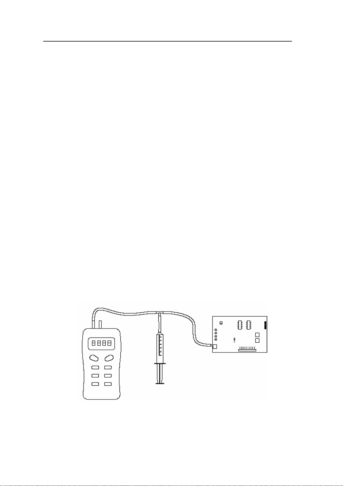
5.2 Pressure Monitor Calibration
Prepare for a barometer with the range of at le
ast 250 Pa and a syringe with the T-type
injected tube, see Figure 10.
FIGURE 10: PRESSURE MONITOR CALIBRATION SETUP
Manometer
, Syringe, Tee Fitting, Sensor Ass’y.
, insert the wire rope; the
22
Page 23

Exhaust filters from top to bottom pressure calibration
(a) Open the front operational panel, unplug the trachea from the pressure sensor NPC1A;
e of T-type injected tube ends connects with NPC1A and one end with barometer and
(b)On
another with syringes.
(c) Press the power button and select exhaust pressure on the display
.
(d) Using syringe pressure control, observe whether the pressure on the screen and the
manometer readings is the same.
(e) Compare these two readings and continuously adjust potentiometers RP1A and RP2A
until the readings are the same.
Correct the air supply filters pressure from top to bottom with the same method.
5.3 Major parts list
Description of parts Number
NSF 49 Support Stand 24.9” High 11239-001
Stainless Steel I.V. Rod with Hooks Consult Factory
Exhaust Collar Consult Factory
Stainless Steel Armrest 4.7” x 3.2” x 3.2” Height 0.79
Fluorescent Lamp (2/box) 64162-003
UV Lamp 64162-004
Down flow Filter 64162-001
Exhaust Flow Filter 64162-002
23
Page 24

5.4Fault finding hints
Problem Solution
The equipment does not
function
(a) Check power at the electrical outlet into which the
equipment is plugged.
(b) Checkthe following three fuse tubes on the circuit to
determine if they are broken:Zero wire fuse tube F4
12.5A, Fire wire fuse tube F5 12.5A, Transformer fuse
tube F6 630mA
(c) Transformer failure or poor connection with wires cannot
provide normal working voltage
Blower does not function (a) Check the motor
(b) Make sure door is completely closed for UV
(c) Check control panel wiring
(d) Check to determineif fuse tube of blower is broken
Motor hums (a) Replace the motor
(b) Fan speed is set too low
Lights do not
function(fluorescent or
(a) The lamp is broken
(b) Some problems with the units on operational panel or
U.V)
wires.
(c) Replace ballast
(d) Check to determineif the fuse tube of light(F1 2.5A) and
UV lamp( F2 2.5A) is broken
Rattling or scraping noise
(a) Check for debris、paper、wrappings、etc., and clean up
from sash motor/blower
(b) The blower may have slipped on the motor drive shaft;
replace the blower.
(c) Check the emergency sash stop, ensure it is not pressed
down
Air flow velocity too low (a) Fan speed is incorrectly set
(b) HEPA filters are loaded; check the static pressure monitor
reading.
(c) Supply/exhaust air flow requires balancing.
Glass door motor not
working
(a) Check to determine if the fuse for the motor is blown,
F8 6.3A
(b) Check motor; replace the motor if necessary
24
Page 25

No power in internal outlet (c) ”Outlet” button on control board is off.
(d) Problem with units on operational panel or wires.
(e) Overloaded protection on outlet wire is tripped or fuse
has been blown.
5.5Maintenance notes
During maintenance, power supply must be turned off before pulling out power plugs. Users
are only allowed to replace UV lamp or fluorescent tubes, while other components should not
be removed. The maintenance of this equipment should only be performed by people who are
trained by Envirco If you need to order parts, you can contact our Technical Services
Department. Be sure to indicate the type and number of the Biological Safety Cabinet.
VI、Installation requiring connection to an external exhaust system
Note: For installations where the exhaust HEPA filters of a Biological Safety Cabinet
are to be connected to an external building exhaust system, it must be a 100%
exhaust system.
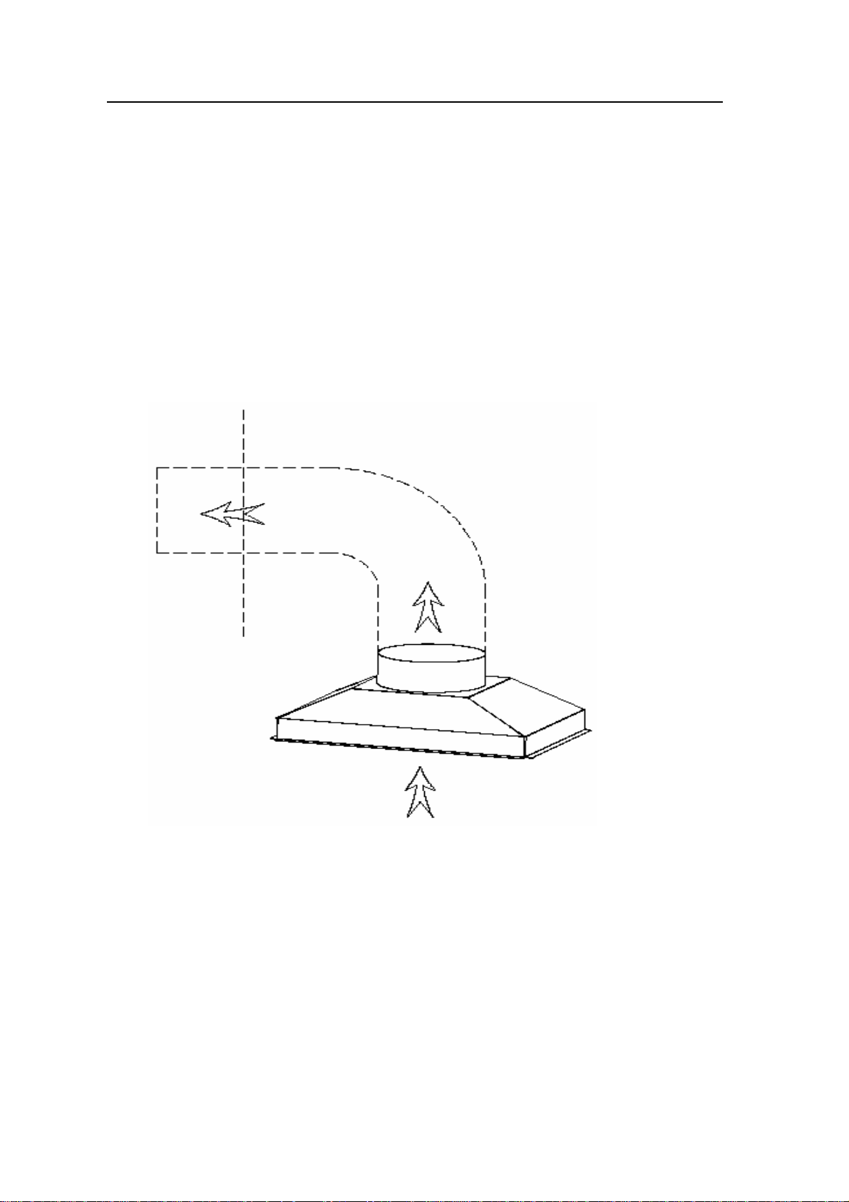
6.1Canopy/thimble connection
(a)Refer to Figure 11 for typical arrangement. The canopy or thimble type connection should
provide a constant exhaust load from the laboratory, regardless of whether the cabinet is
working or not. A duct volume of approximately 58 CFMgreater than the exhaust of the
cabinet is required; the exhaust of this cabinet is 264-282 CFM.
(b)This type of connection can be used when the cabinet is vented into a common exhaust
system.
(c) The opening of the canopy should be checked with a smoke stick to ensure that the
internal air turbulence does not cause outward air leakage.
(d) To ensure that the cabinet is not used without the remote exhaust fan operating, the
building exhaust fan should be interlocked to the outlet used to power the Biological Safety
Cabinet. An alternative method is to use a sail switch or similar device located in the
building exhaust system.
(e)A damper may be required in the exhaust line to correctly set the pull on the canopy.
(f)Balancing should be carried out by qualified personnel.Envirco can supply the exhaust
transition/monitor for coupling to the exhaust duct. Each exhaust transition/monitor
includes an alarm monitor system with a low and high flow alarm.
6.2 Hard connection
25
Page 26
Hard connection is only used in special applications with type A2 Biological Safety Cabinets.
Should your situation require such a configuration, contact Envirco for information.
6.3 Instructions for flow alarm monitor system
Flow alarm monitor system is a pre-programmed, self-contained package that monitors
differential static air pressure. The alarm would note when the air pressure is ±20% beyond
the normal pressure. When the air pressure is 20 % lower than the normal pressure, it hums
three times every five seconds, and when the air pressure is 20 % higher, four times every five
seconds.
FIGURE 11: EXHAUST SYSTEM
26
Page 27
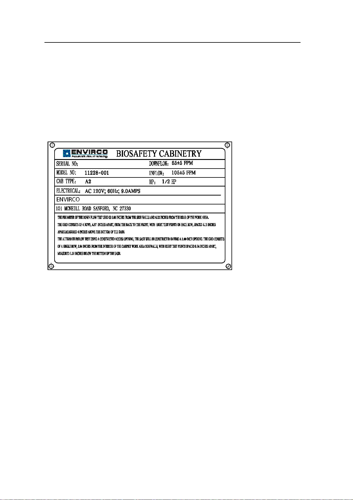
VII、Label instructions
1. Nameplate:Placed on the positive side
27
Page 28
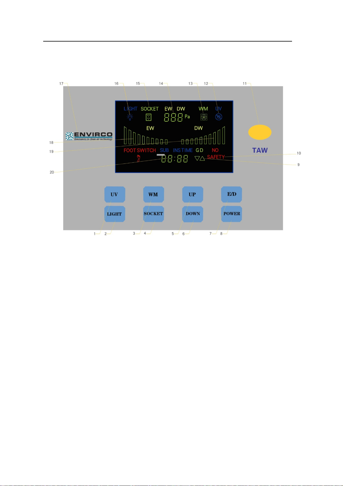
FIGURE 5: CONTROL PANEL
1. Uv–light
. Light
2
3. Wm (fan)
4. Socket
5. Up (control for glass door)
6. Down (control for glass door)
7. E/d (intake and exhaust air changing)
8. Power
9. Display(glass door)
10. Display (security stcabinet)
11. Display (security stcabinet)
12. Remote control receiver
13. UV work state display
14. Blower display
15. Intake or exhaust air display
16. Socket display
17 . Lightdisplay
18. Logo(envirco)
19. Dynamic exhaust air display
20. Dynamic intake air display
21. Time reserve display
28
Page 29
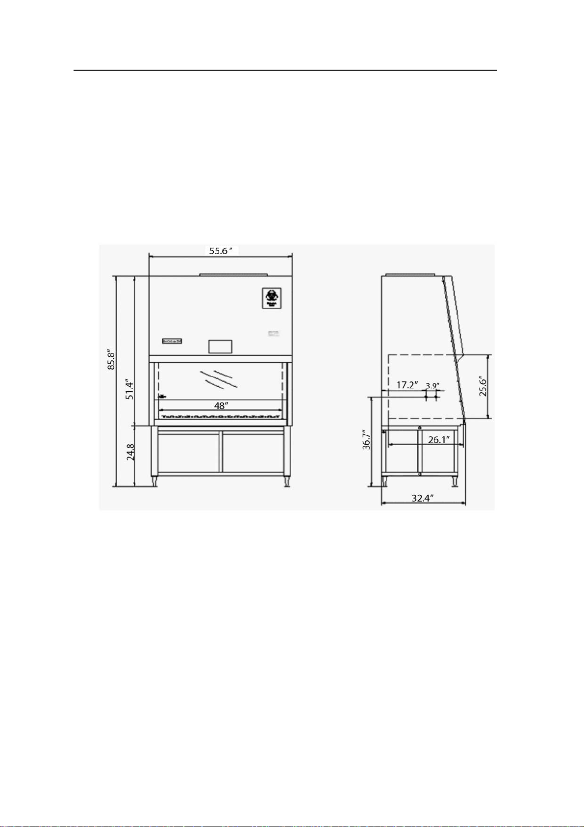
FIGURE 6: MEASUREMENT OF BIOHAZARD CABINET
Front View Side View
29
Page 30
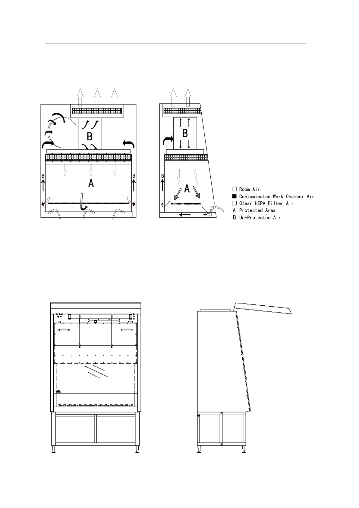
FIGURE 7: AIR FLOW PATTERN AND PROTECTED AREA
Front View Side View
FIGURE 8: FRONT ACCESS PANEL REMOVAL
30
Page 31

Front View Side View
31
Page 32
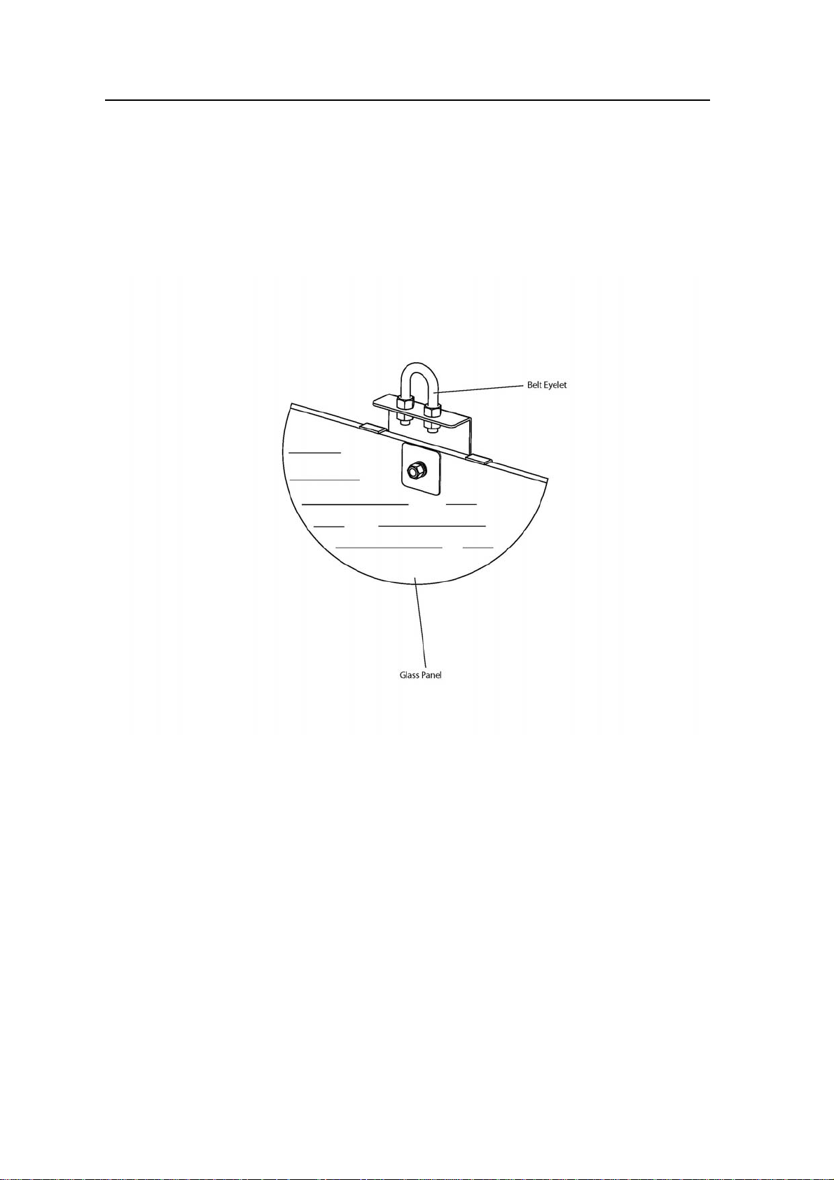
FIGURE9: GLASS CLIP
32
Page 33
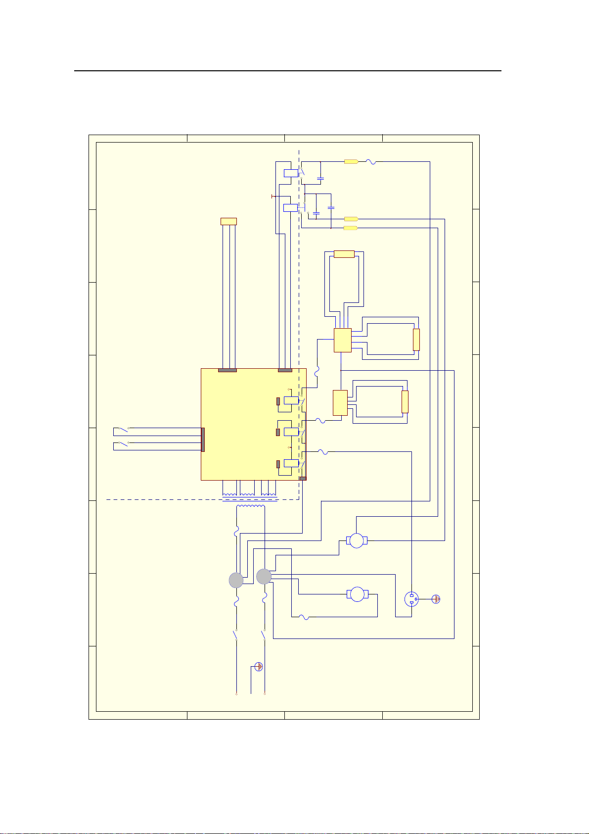
FIGURE 12: ELECTRICAL SCHEMATIC
D
8
7654321
C
JK1
+12V
20AWG
20AWG
20AWG
JK2
+12V
JK1 20AWG
20AWG
JK2 20AWG
JK1
20AWG
20AWG
20AWG
20AWG
24V
5.3V
JK2
+12V +12V
JK3
12V
B
6.3A
C2
0.1UF/27 5V
C3
0.1UF/ 275V
C1
0.1UF/ 275V
20AWG
18AWG
2.5A
F1
F2
2.5A
F3
20AWG
20AWG
18AWG
6.3A
20AWG
20AWG
20AWG
20AWG
20AWG
20AWG
20AWG
20AWG
20AWG
A
18AWG
F6 125mA
18AWG
12.5A
F4
F5 12.5A
14AWG
14AWG
14AWG
L
D
C
18AWG
F7
6.3A
14AWG
18AWG
14AWG
N
16AWG
16AWG
16AWG
18AWG
16AWG
16AWG
1 2 3 4 5 6 78
B
A
33
Page 34

Terms and Conditions
. ACCEPTANCE:
set forth herein, and the Seller identified in the quotation or invoice (as applicable) (“Seller”) agrees to furnish the materials,
goods, products and services (collectively “Goods”) covered thereby only upon these Terms and Conditions of Sale. Any terms
and conditions that may be contained in any purchase order or other form of Buyer shall be absolutely without force and effect,
regardless of when received by Seller. By placing an order, Buyer accepts these Terms and Conditions of Sale, and the sale
and delivery by Seller of Goods shall be conclusively presumed to be subject to these Terms and Conditions of Sale. Seller
reserves the right to accept or reject any order in whole or in part. Possession of a product catalog by Buyer does not constitute
an offer to sell.
2. CANCELLATION:
3. PRICE CHANGES:
time. Goods are invoiced at prices prevailing on the date of shipment.
4. PAYMENT; TAXES:
approved credit, payment shall be made within thirty (30) days of the date of Seller’s invoice. Unpaid amounts shall accrue
interest at a rate equal to the lesser of one and one half percent (1.5%) per month and the maximum rate permitted by
applicable law, from due date until paid, plus Seller’s reasonable costs of collection. In addition, Seller reserves all other rights
granted to a seller under the Uniform Commercial Code for Buyer’s failure to pay for Goods or any other breach by Buyer of
The acceptance of Buyer’s order is expressly made conditional on Buyer’s assent to the terms and conditions
Cancellation or modification of orders are subject to Seller’s prior written consent in each instance.
Prices quoted in Seller’s product catalog are subject to change without notice at any time and from time to
Unless otherwise set forth on Seller’s invoice or otherwise agreed upon by the parties in writing, and upon
these Terms and Conditions of Sale. All stated prices are exclusive of any taxes, fees, duties and levies, however designated or
imposed, including, but not limited to, value added and withholding taxes which are levied or based upon the amounts paid
hereunder (collectively, “Taxes”). Any Taxes related to Goods purchased pursuant to these Terms and Conditions of Sale shall
be paid by Buyer (excluding taxes based on Seller’s net income), unless Buyer presents an exemption certificate acceptable to
Seller and the applicable taxing authorities. Applicable Taxes shall be billed as a separate item on the invoice to the extent
possible.
5. SECURITY INTEREST:
from the sale, exchange, collection, or disposition thereof, until Buyer has made payment in full for such Goods. Buyer shall,
upon request by Seller, provide all information and signatures required by Seller to perfect such security interest. Seller
reserves all rights granted to a secured creditor under the Uniform Commercial Code, including the right to repossess upon
default by Buyer.
6. MODE OF PACKAGING OR SHIPMENT:
However, where Buyer requests special packaging or shipping, any additional cost will be billed to and be the responsibility of
Buyer.
7. DELIVERY:
(Incoterms 2000) and Buyer shall be responsible for all shipping costs. Buyer is advised that quoted ship dates are based on
Unless otherwise agreed to in writing by the parties, Goods shall be delivered EX WORKS Seller’s facility
Seller reserves a purchase money security interest in the Goods delivered hereunder and in proceeds
Seller reserves the right to pack or ship orders in the most economical manner.
estimates at the time of quotation and that Seller will devote its commercially reasonable efforts to meeting such schedules.
However, Seller assumes no liability for additional costs or damages resulting from late deliveries. In addition, on orders for
34
Page 35

non-stock products, or special orders, or where manufacturing processes make it difficult to provide the exact quantity
specified, Seller reserves the right to under-ship or over-ship and invoice Buyer accordingly.
8. RISK OF LOSS:
and agrees that any risk of such loss, damage, or destruction transfers to, and is assumed by, Buyer upon delivery of the Goods
to a common carrier or when otherwise placed in transit.
9. LIMITED WARRANTY:
that Goods are free from defects in material and workmanship, except for services which are warranted to be performed in a
competent and diligent manner in accordance with any mutually agreed specifications. The foregoing warranty shall apply for
twelve (12) months from the date of shipment from Seller’s facility, except for services for which the warranty shall apply for
ninety (90) days from the date of performance (the “Warranty Period”). Provided Buyer informs Seller in writing of any breach of
warranty prior to the expiration of the applicable Warranty Period, Seller shall, as its sole obligation and Buyer’s sole and
exclusive remedy for any breach of this warranty, repair or replace/reperformance the Goods which gave rise to the breach or,
at Seller’ option, refund the amounts paid by Buyer for the Goods which gave rise to the breach. Any repair, replacement or
reperformance by Seller hereunder shall not extend the applicable Warranty Period. The parties shall mutually agree on the
specifications of any test to determine the presence of a defect. Unless otherwise agreed upon by Seller in writing, Buyer shall
bear the costs of access, de-installation, re-installation and transportation of Goods to Seller and back to Buyer. These
warranties and remedies are conditioned upon (a) the proper storage, installation, operation, and maintenance of the Goods
and conformance with the proper operation instruction manuals provided by Seller or its suppliers or subcontractors, (b) Buyer
Seller shall not be liable for any Goods lost, damaged, or destroyed while in transit, and Buyer acknowledges
Unless otherwise expressly stated in Seller’s published specifications for the Goods, Seller warrants
keeping proper records of operation and maintenance during the applicable Warranty Period and providing Seller access to
those records, and (c) modification or repair of the Goods only as authorized by Seller. Seller does not warrant the Goods or any
repaired or replacement parts against normal wear and tear or damage caused by misuse, accident, or use against the
instructions of Seller. Any modification or repair of any of the Goods not authorized by Seller shall render the warranty null and
void.
EXCEPT AS EXPRESSLY SET FORTHHEREIN, SELLER MAKES NO OTHER WARRANTIES, EXPRESS OR
IMPLIED, INCLUDING, BUT NOT LIMITED TO, ANY IMPLIED WARRANTIES OF MERCHANTABILITY,
NON-INFRINGEMENT OR FITNESS FOR A PARTICULAR PURPOSE WHICH ARE HEREBY DISCLAIMED TO THE
EXTENT PERMITTED BY APPLICABLE LAW
10. INDEMNIFICATION:
Seller, its subsidiaries, affiliates, parents, partners, their successors and assigns, and each of their past and present directors,
officers, employees and agents (collectively “Seller Indemnities”), jointly and severally, from and against any and all losses,
damages, liabilities, demands, claims, actions, judgments, charges, court costs, and legal or other expenses, including, without
limitation, reasonable attorneys’ fees and expenses, which Seller Indemnities may sustain, incur, or become liable for in
defending or compromising any suit, action, or other proceeding arising out of, related to, or in any way connected with Buyer’s
purchase, sale, or use of the Goods, including, but not limited to, Buyer’s misuse of such Goods or any other acts or omissions,
willful misconduct or negligent misconduct, whether active or passive, on the part of Buyer; provided, however, Buyer shall
To the fullest extent permitted by applicable law, Buyer agrees to defend, indemnify, and hold harmless
.
have no indemnity obligations under this Section 10 for any losses, damages, liabilities, demands, claims, actions, judgments,
35
Page 36

charges, court costs, and legal or other expenses caused solely by the willful misconduct or negligent misconduct of a Seller
Indemnities or otherwise covered by Seller’s obligations under Section 11.
11. INFRINGEMENT:
action is based upon a claim that the Goods infringe any U.S. patents or copyrights or misappropriate any trade secrets of a
third party, and Seller will pay those costs and damages finally awarded against Buyer in any such action that are specifically
attributable to such claim or those costs and damages agreed to in a monetary settlement of such action. The foregoing
obligations are conditioned on Buyer (a) notifying Seller promptly in writing of such action, (b) making no admission of liability
and giving Seller sole control of the defense thereof and any related settlement negotiations, and (c) cooperating and, at
Seller’s request and expense, assisting in such defense. If the Goods become, or in Seller’s opinion are likely to become, the
subject of an infringement claim, Seller may, at its option and expense, either (i) procure for Buyer the right to continue using
such Goods, (ii) replace or modify such Goods so that they become non-infringing, or (iii) accept return of such Goods and
refund Buyer the amounts actually paid by Buyer to Seller for such Goods. Notwithstanding the foregoing, Seller will have no
obligation under this Section 11 or otherwise with respect to any infringement claim based upon (A) any use of the Goods not in
accordance with these Terms and Conditions of Sale or Seller’s instructions, (B) any use of the Goods in combination with other
materials, goods, products or services not intended by Seller to be used with the Goods, (C) failure of Buyer to implement any
update provided by Seller that would have prevented the claim, (D) any modification of the Goods by any person other than
Seller or its authorized agents or subcontractors, or (E) any Goods made or performed to Buyer’s specifications or designs.
THIS SECTION 11 STATES SELLER’S ENTIRE LIABILITY AND BUY’ER’S EXCLUSIVE REMEDY FOR I NFRINGEMENT
Seller will defend at its own expense any action against Buyer brought by a third party to the extent that the
CLAIMS AN D ACTION S.
12. LIMITATION OF LIABILITY:
EXEMPLARY OR CONSEQUENTIAL DAMAGES, INCLUDING WITHOUT LIMITATION ANY LOST DATA, LOST PROFITS
AND COSTS OF PROCUREMENT OF SUBSTITUTE GOODS OR SERVICES, REGARDLESS OF THE FORM OF ACTION,
WHETHER IN CONTRACT, TORT OR OTHERWISE, EVEN IF SELLER HAS BEEN ADVISED OF THE POSSIBILITY OF
SUCH DAMAGES. SELLER’S TOTAL LIABILITY FOR ALL CLAIMS ARISING OUT OF OR RELATING TO ANY GOODS
SHALL BE LIMITED TO GENERAL MONEY DAMAGES IN AN AMOUNT NOT TO EXCEED THE TOTAL PURCHASE PRICE
FOR THE GOODS GIVING RISE TO THE CLAIM.
13. DESIGN CHANGES:
previous shipments to Buyer.
14. NO LICENSE:
trade names, or other proprietary rights owned or controlled by Seller, its subsidiaries, affiliates, or suppliers; it being
specifically understood and agreed that all such rights are reserved to Seller, its subsidiaries, affiliates, or suppliers. Without
limiting the foregoing, Buyer will not, without Seller’s prior written consent, use any trademark or trade name of Seller in
connection with any Goods, other than with respect to the resale of Goods pre-marked or packaged by or on behalf of Seller.
15. FORCE MAJEURE:
The sale of Goods shall not confer upon Buyer any license, express or implied, under any patents, trademarks,
Seller shall not be liable for any failures or delays caused by strikes, differences with workers, or any
IN NO EVENT WILL SELLER BE LIABLE FOR ANY INDIRECT, SPECIAL, INCIDENTAL,
Seller reserves the right to alter, modify, or redesign its products without any obligation to replace
causes beyond the reasonable control of Seller, including but not limited to, fires, floods, accidents, action of any governmental
authority, war, insurrection or riots, or shortages of labor, energy, raw materials, production facilities, or transportation. Where
36
Page 37

delays or failures are caused by labor difficulties, Seller shall not be obligated to seek or obtain any settlement which, in Seller’
sole judgment, is not in Seller’ best interest.
16. COMPLIANCE:
no event shall Buyer take any action(s) contrary to the United States export laws and regulations in effect as of the date of
shipment of the Goods, including without limitation, diversion of Goods. Seller is U.S. Customs-Trade Partnership Against
Terrorism (C-TPAT) certified. Seller’s status verification interface (SVI) number will be provided upon Buyer’s written request.
17. GOVERNING LAW AND VENUE:
USA, without reference to any conflict of laws principles that would require the application of the laws of any other jurisdiction.
The United Nations Convention on Contracts for the International Sale of Goods shall not apply. Buyer irrevocably consents to
the personal jurisdiction of the state and federal courts located in the State of Colorado, USA, for any suit or action arising from
or related to the Goods, and waives any right Buyer may have to object to the venue of such courts. Buyer further agrees that
these courts will have exclusive jurisdiction over any such suit or action initiated by Buyer against Seller.
18. CHOICE OF LANGUAGE:
documents be drafted in English. Il est de l’intentionexpresse des parties à la présente Convention (connaissement, bon de
commande,bon de conditionnementou facture) et tout document s’yrattachantsoientécrit en langue anglaise.
19. MISCELLANEOUS:
representation or warranty not expressly set forth herein. This document constitutes the entire agreement of the parties and
supersedes all existing agreements and all other oral or written communications between them concerning its subject matter.
Each party shall comply with all applicable laws, regulations, and ordinances. Without limiting the foregoing, in
These Terms and Conditions of Sale shall be governed by the laws of the State of Colorado,
It is by the express intention of the parties hereto that the present Agreement and all its related
Buyer acknowledges that is has not been induced to purchase any Goods from Seller by any
None of the terms and conditions contained herein may be added to, modified, superseded, or otherwise altered except by a
written document signed by an authorized representative of Seller. Any waiver or failure to enforce any provision herein on one
occasion will not be deemed a waiver of any other provision or of such provision on any other occasion. The Section headings
contained herein are intended for convenience of reference only and shall not affect the interpretation of any provision. If any
provision of this Agreement is held to be prohibited or unenforceable, such provision will be changed and interpreted to
accomplish the objectives of such provision to the greatest extent possible under applicable law and the remaining provisions
will continue in full force and effect. Buyer may not assign any quotation or order for Goods, in whole or in part, without Seller’s
prior written consent.
37
Page 38

101 McNeill
Rd., Sanford, NC 27330
www.envirco.com
800.884.8002
38
 Loading...