


Visit the ENTTEC website for
the latest version
OCTO – User Guide
8 universe eDMX to LED pixel controller with network chaining in a compact 4-module DIN-rail form factor.
OCTO – 71521
ENTTEC’s OCTO is a robust and reliable
installation grade LED controller
engineered to take any architectural,
commercial or entertainment project to
the next level.
With 8 universes of eDMX to pixel
protocol conversion and network
chaining between devices, the OCTO
allows for fast deployment of LED strips
and pixel dot systems compatible with a
wide range of devices.
The OCTO is packed with installerfriendly features such as an identify
button to check correct wiring,
temperature monitoring, a wide input
voltage range and intuitive configuration
and management through its localhost
web interface. All contained within a 4
DIN unit form factor.
The inbuilt Fx engine allows users to edit
and create presets, using the OCTO’s web
interface that can be configured to run
standalone at power up.
FEATURES
Two * 4-universe pixel outputs with Data
and Clock support.
Support for up to 8 universes of Art-Net,
sACN, KiNet and ESP.
Easily extendable network - daisy chain
ethernet connection between devices.
DHCP or Static IP address support.
Multiple pixel protocols supported, see:
www.enttec.com/support/supportedled-pixel-protocols.
Surface or TS35 DIN rail mounting option.
Intuitive device configuration and updates
through the inbuilt web interface.
Test/Reset button allows installers to
quickly check wiring is correct without
requiring a network connection.
Simple Fx generator mode to create and
execute preset effects on the fly,
configurable to play from power up.
Grouping functionality to reduce input
channel count.
1 |
ID: 5928937
USER GUIDE - v1.0

Visit the ENTTEC website for
the latest version
Contents
Contents ...................................................................................................................................................................................................................... 2
Electrical safety ............................................................................................................................................................................................................................. 4
Installation ...................................................................................................................................................................................................................................... 5
Protection from injury during installation ..................................................................................................................................................................... 5
Installation safety guidelines ................................................................................................................................................................................................ 5
Physical dimensions .................................................................................................................................................................................................................. 6
Mounting options ........................................................................................................................................................................................................................ 6
Functional features .............................................................................................................................................................................................. 8
Hardware features ................................................................................................................................................................................................ 9
LED status indicator ................................................................................................................................................................................................................... 9
Identify / Reset button ............................................................................................................................................................................................................. 9
Default IP ................................................................................................................................................................................................................. 10
Finding an OCTO’s IP address using ENTTEC NMU ................................................................................................................................................... 10
OCTO – 71521
Web configuration ................................................................................................................................................................................................ 11
Home ................................................................................................................................................................................................................................................ 12
Settings ........................................................................................................................................................................................................................................... 13
Direct .......................................................................................................................................................................................................................... 13
DMX protocols ....................................................................................................................................................................................................... 14
KiNET................................................................................................................................................................................................................................................. 14
Art-Net ............................................................................................................................................................................................................................................. 14
sACN .................................................................................................................................................................................................................................................. 14
ESP ..................................................................................................................................................................................................................................................... 14
Universes/Outputs .................................................................................................................................................................................................................... 14
Group pixels.................................................................................................................................................................................................................................. 15
DMX start address ..................................................................................................................................................................................................................... 15
Standalone............................................................................................................................................................................................................... 15
Show options – Activating a standalone effect ......................................................................................................................................................... 16
Creating a standalone effect ............................................................................................................................................................................................... 17
Editing a standalone effect ................................................................................................................................................................................................. 20
Deleting a standalone effect .............................................................................................................................................................................................. 20
Copying a standalone show ................................................................................................................................................................................................. 21
Importing and exporting a standalone list .................................................................................................................................................................. 21
Network stats ......................................................................................................................................................................................................... 22
Art-Net ............................................................................................................................................................................................................................................ 22
ESP .................................................................................................................................................................................................................................................... 22
sACN ................................................................................................................................................................................................................................................. 22
KiNET................................................................................................................................................................................................................................................ 23
Updating firmware .............................................................................................................................................................................................. 23
Reset to factory defaults ................................................................................................................................................................................. 24
Using web interface ................................................................................................................................................................................................................. 24
Using the reset button ........................................................................................................................................................................................................... 24
Tips and guidelines ............................................................................................................................................................................................ 25
2 |
ID: 5928937
USER GUIDE - v1.0

Visit the ENTTEC website for
the latest version
Servicing, inspection & maintenance ........................................................................................................................................................ 26
OCTO – 71521
Cleaning .......................................................................................................................................................................................................................................... 27
Package contents ................................................................................................................................................................................................ 28
Ordering information ........................................................................................................................................................................................ 28
3 |
ID: 5928937
USER GUIDE - v1.0

Ensure you are familiarized with all key information within this guide and other relevant ENTTEC
documentation before specifying, installing, or operating an ENTTEC OCTO. If you are in any doubt
about system safety, or you plan to install ENTTEC’s OCTO in a configuration that is not covered
within this guide, contact ENTTEC or your ENTTEC supplier for assistance.
ENTTEC’s return to base warranty for this product does not cover damage caused by inappropriate
use, application, or modification to the product.
Electrical safety
This product must be installed in accordance with applicable national and local electrical and
construction codes by a person familiar with the construction and operation of the product and the
hazards involved. Failure to comply with the following installation instructions may result in death or
serious injury.
This device can be damaged by excess voltage outside the operating range defined within this
products datasheet.
To reduce the risk of fire or electrical faults do not exceed the ratings and limitations defined in the
product datasheet or this guide.
Provide a means of locking out power to your installation for system servicing and maintenance.
Before applying power to your installation, ensure your installation follows the wiring schematics
defined within the guide.
Ensure there are no opportunities for cables to short circuit and cabling cannot be snagged or pulled.
Do not over stretch cabling to the OCTO’s connectors and ensure that cabling does not exert force on
the PCB.
Before applying power to your installation, check that all power distribution equipment and cables
are in perfect condition and rated for the current requirements of all connected devices and factor
in overhead.
Isolate your installation from power immediately if accessories power cables or connectors is in any
way damaged, defective, shows signs of overheating or are wet.
Do not ‘hot swap’ or ‘hot plug’ power to the OCTO or its accessories.
Shut down power to the installation during cleaning or when the system is not in use.
Before connecting OCTO’s to a power supply, verify that it is appropriately fused and voltage is
compatible.
Ensure that no part of the installation is or can be connected to power until all work is complete.
Always refer to this product’s safety notes and installation guidelines before handling or specifying
it on your project.
Do not leave loose wires around this device whilst in operation, this could result in short circuiting.
Do not connect this device to a dimmer pack or mains electricity.
Do not connect any of this devices DG V- (GND) connectors to earth.
Ensure your installation is protected from short circuits and overcurrent.
Ensure all connections are complete and secure before providing power to the device.
OCTO – 71521
Visit the ENTTEC website for
the latest version
System planning and specification
To contribute to an optimal operating temperature, where possible keep this device out of direct
sunlight.
Pixel data is unidirectional. Ensure that your OCTO is connected to your pixel dots or tape in a way
that ensures data is flowing from the OCTO to the ‘Data IN’ connection of your pixels.
The maximum recommended cable distance between the OCTO’s data output and first pixel is 3m
(9.84ft). ENTTEC advises against running data cabling close to sources of electromagnetic interference
(EMF) i.e., mains power cabling / air conditioning units.
This unit has an IP20 rating and is not designed to be exposed to moisture or condensing humidity.
Ensure this device is only operated within the specified ranges within the product datasheet.
4 |
ID: 5928937
USER GUIDE - v1.0
Installation
Installation of this product must be performed by qualified personnel. If ever unsure always consult
a professional.
Always work with a plan of the installation that respects all system limitations as defined within this
guide and product datasheet.
Keep the OCTO and its accessories in its protective packaging until final installation.
Note the serial number of each OCTO and add it to your layout plan for future reference when
servicing.
All network cabling should be terminated with an RJ45 connector in accordance with the T-568B
standard.
Protection from injury during installation
Always use suitable personal protective equipment when installing ENTTEC products.
Once installation is completed, check that all hardware and components are securely in place and
fastened to supporting structures.
OCTO – 71521
Visit the ENTTEC website for
the latest version
Installation safety guidelines
The OCTO is convection cooled, ensure it receives sufficient airflow so heat can be dissipated.
Do not cover the OCTO with insulating material of any kind.
Do not operate the OCTO if the ambient temperature exceeds 50° C (122° F).
Do not cover or enclose the OCTO without a suitable and proven method of dissipating heat.
Do not install the OCTO in damp or wet environments.
Do not modify the OCTO hardware in any way.
Do not install the OCTO if you see any signs of damage.
Do not handle the OCTO in an energized state.
Do not crush or clamp the OCTO during installation.
Do not sign off a system without ensuring all cabling to the OCTO and accessories has been
appropriately restrained, secured and is not under tension from the way it has been installed.
5 |
ID: 5928937
USER GUIDE - v1.0
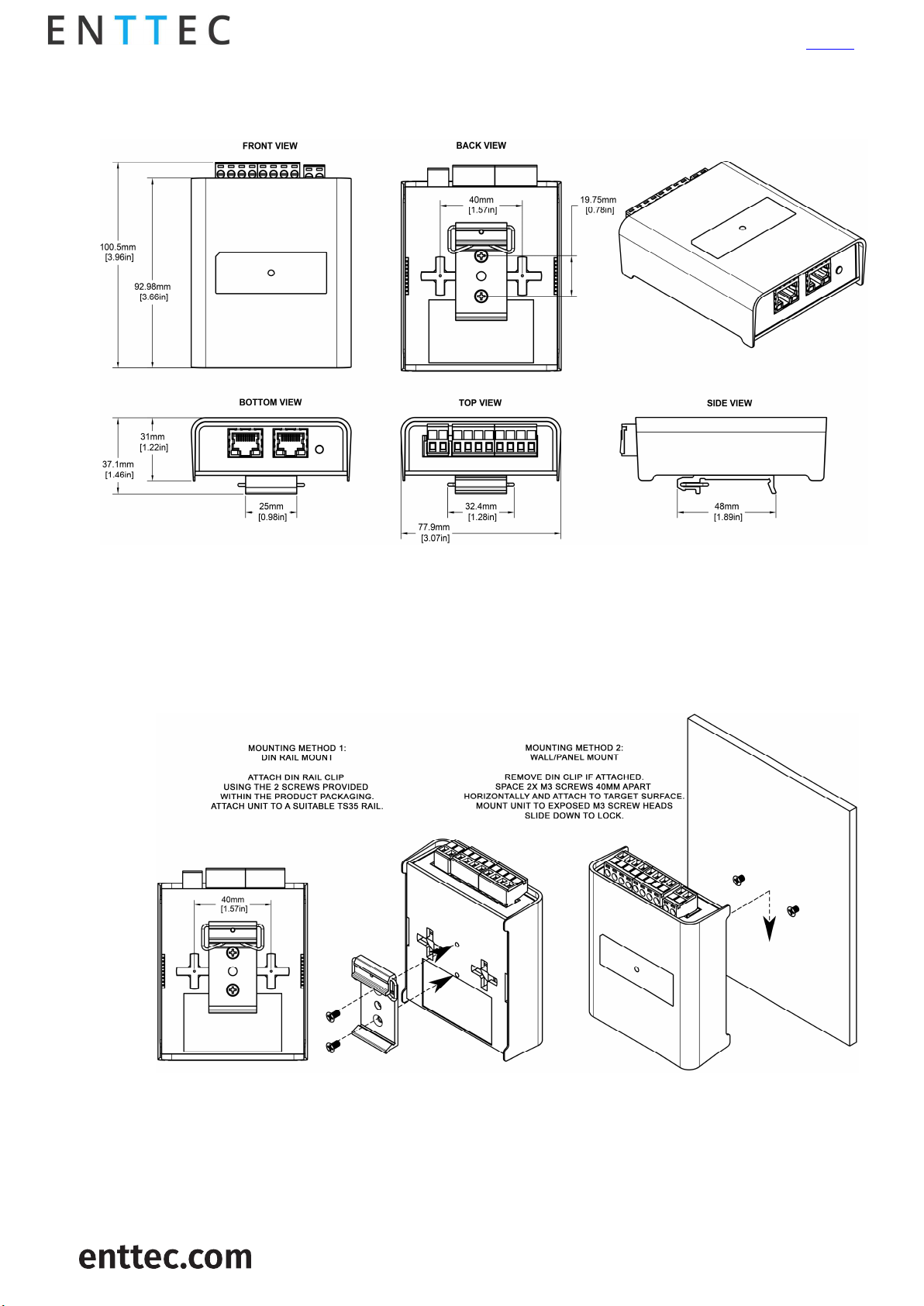
Physical dimensions
OCTO – 71521
Visit the ENTTEC website for
the latest version
Note: The OCTO is 4 DIN modules wide.
Mounting options
Note: The surface mount tabs have been designed to hold the weight of the OCTO only, excess force
by caused by cable strain can cause damage.
6 |
ID: 5928937
USER GUIDE - v1.0

Wiring diagrams
Locate the OCTO and PSU as close as possible to the first pixel in your chain to reduce the impact of
voltage drop.
To reduce the likelihood of voltage or Electro Magnetic Interference (EMI) being induced on the
control signal lines, where possible, run control cabling away from mains electricity or devices that
produce high EMI, (i.e., air conditioning units). ENTTEC recommends a maximum data cable distance
of 3 meters. The lower the cable distance, the lower the impact of voltage drop.
To ensure a reliable connection, ENTTEC recommends the use of cable ferrules for all stranded cables
connected to the OCTO’s screw terminals.
OCTO – 71521
Visit the ENTTEC website for
the latest version
7 |
ID: 5928937
USER GUIDE - v1.0

Visit the ENTTEC website for
OCTO – 71521
the latest version
Functional features
The OCTO supports the following input protocols:
o Art-Net
o Streaming ACN (sACN)
o KiNET
o ESP
The OCTO is compatible with synchronous and asynchronous pixel protocols. For the latest list please
refer to: www.enttec.com/support/supported-led-pixel-protocols/.
RGB, RGBW and White Pixel Order support
User-friendly interface to create and execute live effects on the fly
Save effects to play from power up.
Maximum output refresh rate is 46 frames per second.
8 |
ID: 5928937
USER GUIDE - v1.0
Hardware features
Electrically insulated ABS plastic housing.
Forward facing LED status indicator.
Identify / Reset button.
Pluggable terminal blocks.
Link & Activity LED indicator built into each RJ45 port.
Easily extendable network – daisy chain up to 8 units if the output is in direct mode to ensure
sync between pixels. If using in Standalone mode, a maximum of 50 devices can be linked per
chain.
Surface mount or TS35 DIN mount (using provided DIN Clip accessory).
Flexible wiring configuration.
35mm DIN rail accessory (included in packaging).
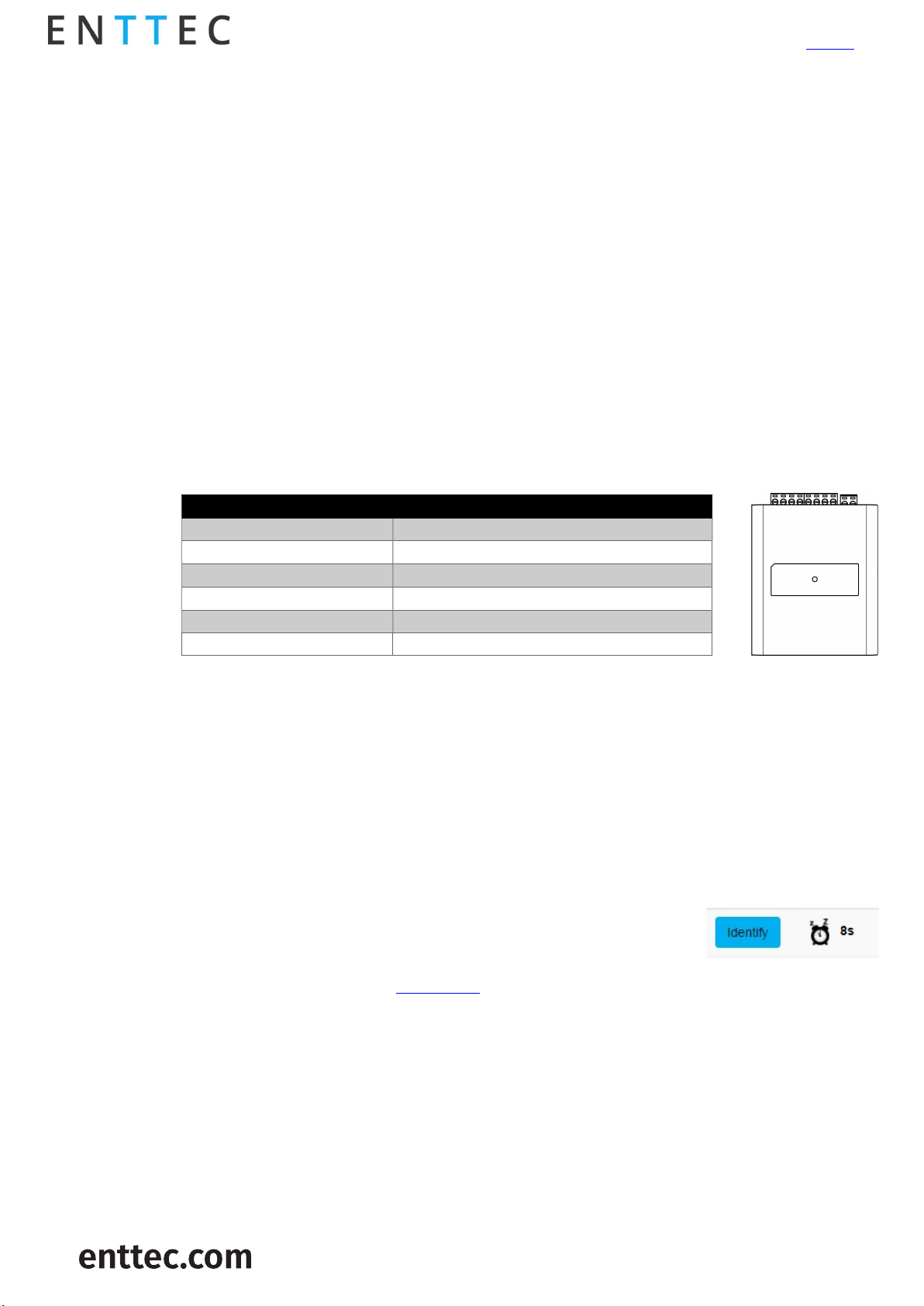
LED status indicator
The LED status indicator can be used to determine the OCTO’s current state. Each state is as
follows:
LED Color OCTO Status
White (static) Idle
Flashing Green Direct mode data receiving
Black over White Standalone mode
Red over Green Multiple merge sources
Purple IP conflict
Red Device in boot / error
OCTO – 71521
Visit the ENTTEC website for
the latest version
Identify / Reset button
As the name suggests, this button can be used to either:
Identify pixels connected to a specific OCTO without the need to provide control data.
When the button is pressed in standard operation, all 8 output universes are set to output
the highest value (255) for 10 seconds before resuming their previous state. This is a good
test to ensure all outputs are connected and working as intended.
Node:
The timer will not restart when pressed consecutively.
Reset the OCTO (Refer to the Reset OCTO section).
9 |
ID: 5928937
USER GUIDE - v1.0

Default IP
Out of the box, the OCTO is factory configured to use DHCP. You can plug it into your existing router,
and it’ll receive an IP address.
If the OCTO cannot obtain an IP address using DHCP, or the router is slow to assign an IP address to it,
it will fall back to its default static IP 192.168.0.10 (default).
The OCTO’s inbuilt web interface can be accessed by entering its IP address into any modern web
browser. The web interface allows the settings of the unit to be changed.
Note: When configuring multiple OCTO’s on a Static network; to avoid IP conflicts, ENTTEC recommends
connecting one device at a time to the network and configuring an IP.
If using DHCP as your IP addressing method, ENTTEC recommends the use of the sACN protocol,
ENTTEC does not recommend unicasting data to a device with it’s IP address set through DHCP
or ArtNet Broadcast. This will ensure that your OCTO continues to receive data if the DHCP server
changes it’s IP address.
server on long term installations.
Visit the ENTTEC website for
OCTO – 71521
the latest version
Finding an OCTO’s IP address using ENTTEC NMU
ENTTEC provides a free App (available for Windows and OSX 10.7-10.11) called NMU (Node Management
Utility). NMU finds ENTTEC devices and displays their IP addresses allowing navigation to the IP easier.
Note:
The OCTO is supported by NMU V1.93 and above.
To discover a device using ENTTEC NMU follow the steps below:
1. Download NMU from www.enttec.com.
2. Connect your computer to the same network as your ENTTEC devices.
3. Open NMU. If prompted to select a network interface, select the correct one to which the
OCTO is connected to.
4. Press the Discovery button and wait until NMU finds all supported ENTTEC devices.
5. Once found, select your device then press ‘configure’ to access its web-interface.
10 |
ID: 5928937
USER GUIDE - v1.0

Web configuration
The OCTO can be configured and controlled through a web browser, running on a computer system,
located on the same Local Area Network (LAN).
Note:
A Chromium based browser is recommended for accessing the OCTO web interface.
Either click on the underlined URL displayed in NMU or type the IP address (as detected by NMU e.g.:
10.10.3.26) into your web browser to access the web interface.
The top menu allows all the OCTO web pages to be accessed.
OCTO – 71521
Visit the ENTTEC website for
the latest version
Menu option is highlighted blue to indicate which page the user is on.
The web interface shows the word Direct or Standalone depending on the mode the device is in, as
displayed in the images below:
.
11 |
ID: 5928937
USER GUIDE - v1.0

Home
The Home tab displays the following information:
DHCP status – (either enabled / disabled)
IP address
Netmask
Gateway
Mac Address
Link Speed
Device Name
Firmware version on device
Serial number of the device
Internal temperature of the processor
System uptime
Input protocol set on device
Output LED protocol set on device
OCTO – 71521
Visit the ENTTEC website for
the latest version
12 |
ID: 5928937
USER GUIDE - v1.0

Settings
OCTO – 71521
Visit the ENTTEC website for
the latest version
The Settings page allows a user to do the following:
Change a device name for identification
Enable/disable DHCP
Specify static network settings
Set the output LED Protocol
Set the number of mapped pixels
Configure how colors are mapped to pixels through the Pixel Order function.
Reset to factory defaults
Reboot the device
Direct
Direct mode can be activated by clicking on the ‘Use Direct mode’ button on the Direct page as shown
in the image below.
When activated, the word Direct will be displayed next to the ENTTEC logo as shown in the
screengrab above:
13 |
ID: 5928937
USER GUIDE - v1.0

DMX protocols
KiNET
Supported commands:
Discover device
Discover ports on device
Change device name
Change device IP
Portout commands
DMX out commands
KGet Command
KGet Subnet Mask
KGet Gateway
KGet port universe (port 1 and 2)
KSet commands
KSet Subnet Mask
KSet Gateway
KSet port universe (port 1 and 2)
KSet device to boot
OCTO – 71521
Visit the ENTTEC website for
the latest version
Art-Net
Supports Art-NET 1/2/3. Each output port can be assigned a start universe in the range 0 to 32764.
sACN
Outputs can be assigned a start universe in the range 1-63996 (when universe/output = 4).
Note
The OCTO supports a maximum of 1 multicast universe with sACN sync. (i.e., all universes set to the
same value)
ESP
Outputs can be assigned a start universe in the range 0-252 (when universe/output = 4). More
details of the ESP protocol can be found at www.enttec.com
Universes/Outputs
The OCTO converts up to four universes of DMX over Ethernet to pixel data per output.
Both outputs can be specified to use the same universes, e.g., both outputs use universe 1,2,3 and 4.
Each output can also be specified to use its own individual group of universes, e.g., output 1 uses
universes 100,101,102 and 103 however output 2 uses 1,2,3 and 4.
Only the first universe can be specified; the remaining universes, second, third and fourth are
automatically assigned subsequent universes to the first one.
14 |
ID: 5928937
USER GUIDE - v1.0

Example:
If the first universe is assigned 9, the second, third and fourth universes will be automatically
assigned 10, 11 and 12 as shown in the image below.
Visit the ENTTEC website for
OCTO – 71521
the latest version
Group pixels
This setting allows multiple pixels to be controlled as one ‘virtual pixel’. This reduces the overall
amount of input channels required to control pixel strip or dots.
Example:
When ‘group pixel’ is set to 10 on an OCTO connected to a length of RGB pixel strip, by patching a
single RGB pixel within your control software and sending the values to the OCTO, the first 10 LED’s
would respond to it.
Note:
The maximum number of physical LED pixels that can be connected to each OCTO is 680 (RGB) or 512
(RGBW). When grouping pixels, the number of control channels required is reduced, this function
does not increase the number of physical LED’s each OCTO can control.
DMX start address
Selects DMX channel number, which controls the first pixel. When the universes/output is more than
one, the DMX start address only applies to the first universe.
However, where it applies, a start address offset may result in the split of a pixel. e.g., R channel in
first universe and GB channels in the seconds universe for a RGB LED.
For ease of pixel mapping, ENTTEC recommend offsetting the DMX start address to a number divisible
by the number of channels per pixel. i.e.:
Increments of 3 for RGB (i.e., 1,4,7, 10)
Increments of 4 for RGBW (i.e., 1,5,9,13)
Increments of 6 for RGB-16 bit (i.e., 1,7,13,19)
Increments of 8 for RGBW-16 bits (i.e., 1,9,17,25)
Standalone
Standalone is to be used to create a looping effect that can be played back from the point the OCTO
is powered on. – This can also be of use to test the OCTO’s output without the need to send eDMX
data.
Standalone can be activated by clicking on the ‘Use Standalone mode’ button as shown below:
15 |
ID: 5928937
USER GUIDE - v1.0
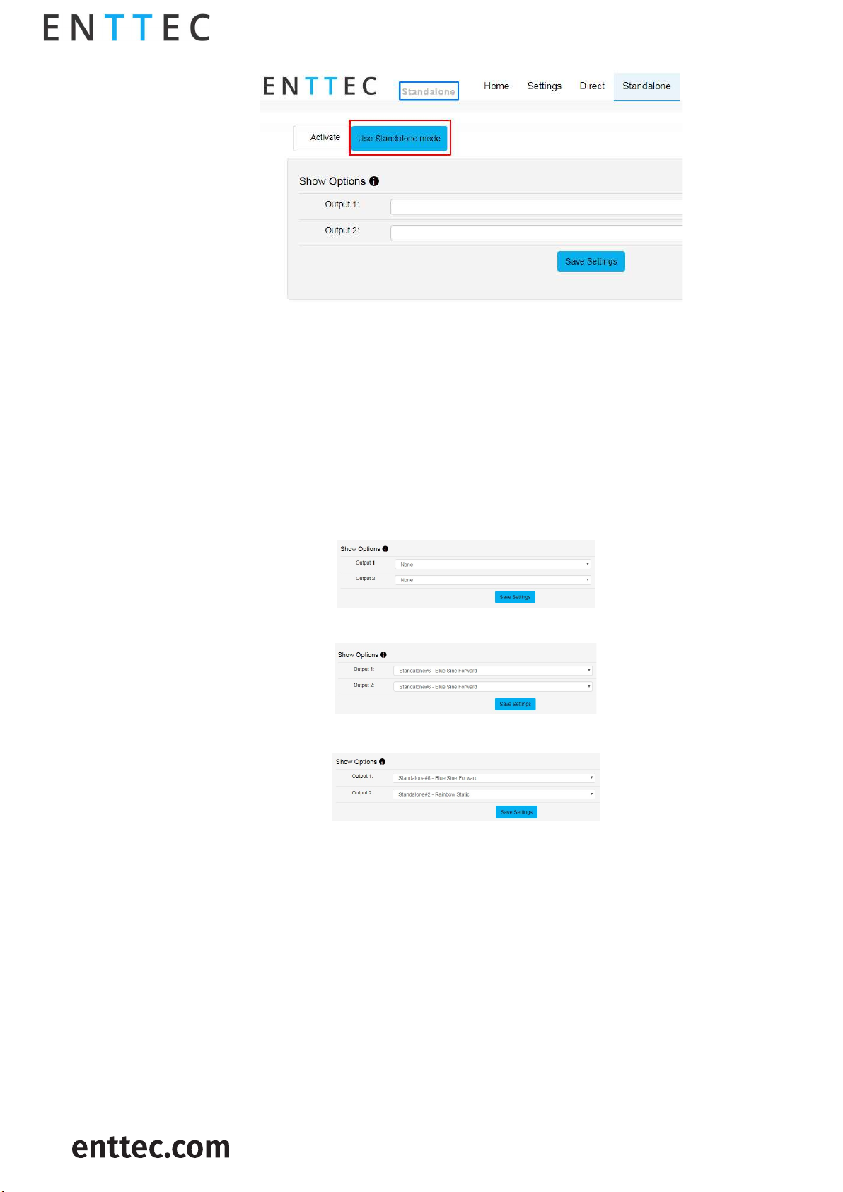
When activated, the word Standalone will be displayed next to the ENTTEC logo.
Note
When operating in Standalone mode:
16Bit protocols are not supported
RGBW tapes are supported but white cannot be controlled.
Visit the ENTTEC website for
OCTO – 71521
the latest version
Show options – Activating a standalone effect
The OCTO allows the control of standalone effects on both outputs. This is controlled by the Show
Options section. Both can be set to output no standalone show:
The outputs can play the same standalone show concurrently:
Or each can be set to output a different show:
.
16 |
ID: 5928937
USER GUIDE - v1.0
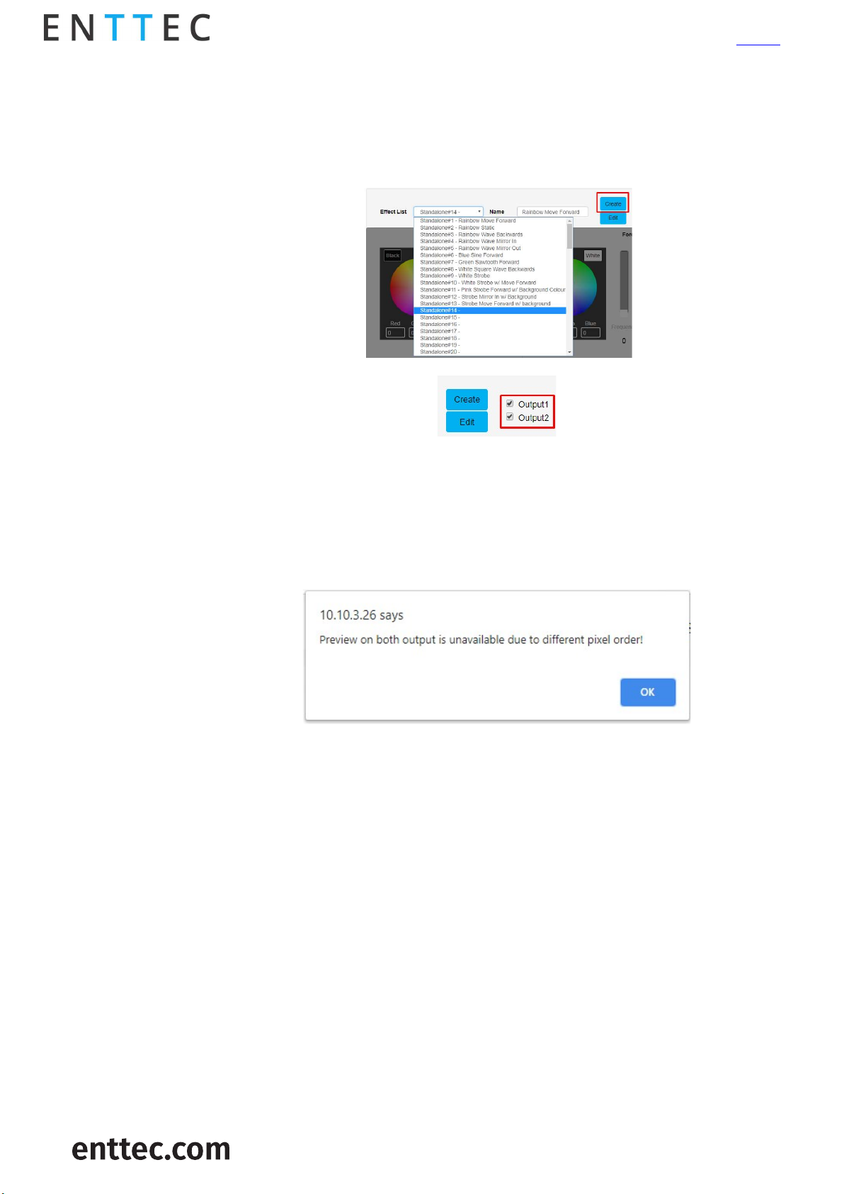
Creating a standalone effect
A standalone show can only be created when Standalone mode is activated. Follow the steps
below to create a standalone (effect):
1. Select the next available standalone slot and click on the Create button
OCTO – 71521
Visit the ENTTEC website for
the latest version
2. Select an output to preview the standalone show on by using the check boxes
3. If the effect previewed is to be preserved, Type in a name and click on Save Effect button
Preview standalone effects
OCTO allows the preview of the standalone. Select the output to preview the standalone as
shown in the previous image.
If two different colour orders e.g.: RGB on output 1 and WWA in output 2 are assigned you can
only preview the effect on one output at a time. If you attempt to preview both outputs the
following message is displayed.
Standalone effects name
Up to 65 characters can be used for a standalone name. All characters are supported except
comma (,). The OCTO does not allow a standalone to be saved with an existing name on the
list.
17 |
ID: 5928937
USER GUIDE - v1.0
Visit the ENTTEC website for
the latest version
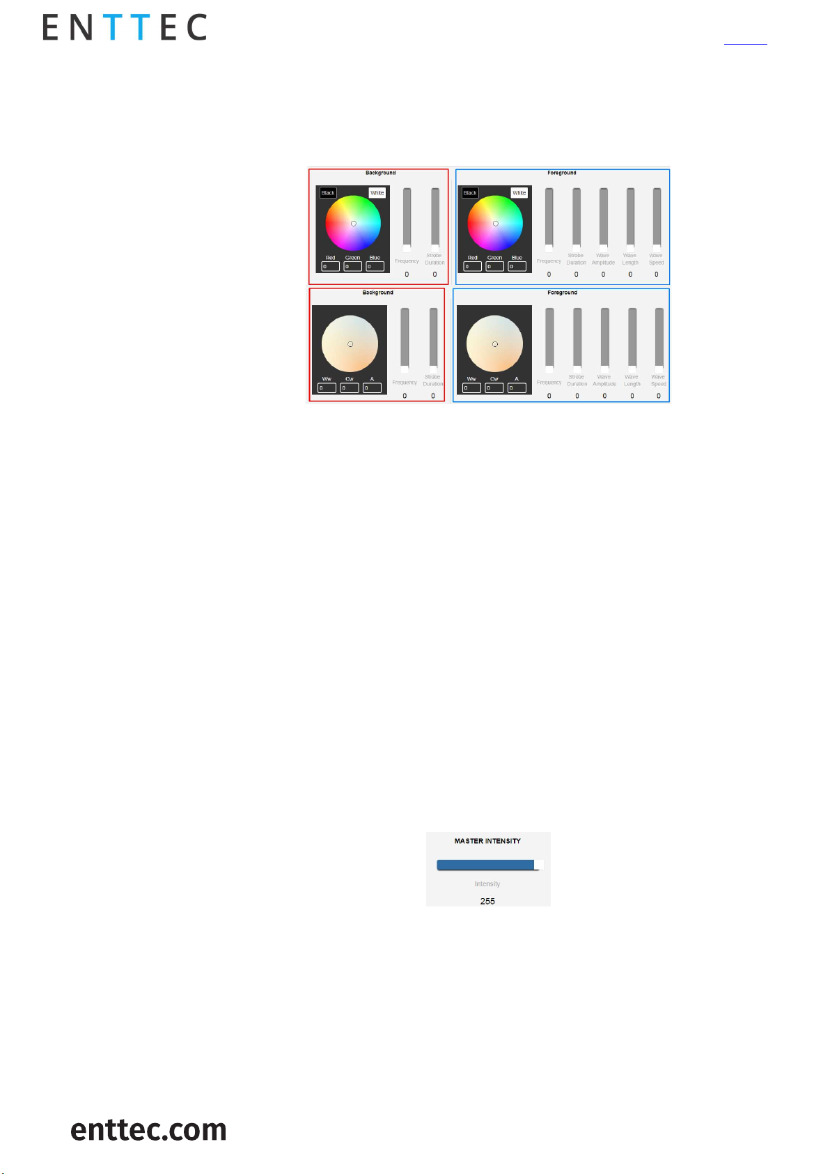
Standalone layers explained
When creating a standalone the light output should be visualized as two layers:
Background (controls shown in red)
Foreground (controls shown in blue)
OCTO – 71521
The OCTO has colour wheel support for both RGB WWA (warm white, cool white and Amber)
pixel tape
Background
By only enabling the background layer the pixel tape/dots will respond like a standard RGB
tape. The background can be:
Set to a constant color.
Dimmed
Made to strobe
The controllers affect the entire length up to the maximum possible pixels (e.g., 680 3-
channel pixels).
Foreground
This layer creates effects that overlay on the background colour. The foreground can be:
Set to a constant color.
Dimmed
Made to strobe
Set to create patterns
Master intensity
Master intensity controls the overall brightness of the output (both for foreground and
background). Where:
0 – no LEDs ON
255 – LEDs on are at full brightness
Background/ foreground strobe frequency
Controls the time between LED(s) on and off time:
0 – LEDs switch on and off at slowest speed
255 – LEDs switch on and off at fastest speed
18 |
ID: 5928937
USER GUIDE - v1.0

Visit the ENTTEC website for
the latest version
Background/ foreground strobe duration
OCTO – 71521
Controls the time that the LEDs are on:
DMX fader value On time
0 Always on
1 Smallest duration
255 Longest duration
Wave function
The foreground layer can be controlled to form patterns of the following wave functions:
Sine wave
Log wave
Square wave
Sawtooth wave
Rainbow Sine Wave
Rainbow Log Wave
Rainbow Square Wave
Rainbow Sawtooth
Wave direction
The wave pattern can be set to travel. Wave direction setting determines which way the
pattern will travel. The wave can be set to move:
Forward
Backward
Mirror out – pattern travelling out of center.
Mirror in – pattern travelling into center.
Wave amplitude
This setting determines the brightness of each pixel in a period of the wave.
DMX fader value Brightness of pixels per wave period
0 Vary between 50% and full
255 Vary between off and full on.
Wavelength
This setting determines the number of pixels in one period of the wave.
DMX fader value Wavelength
0-1 2 pixels
2-255 Fader Value
Wave speed
This setting controls the speed at which the wave pattern travels across tape.
DMX fader value Speed
0 Minimum speed
255 Maximum speed
Offset
Offset allows the pattern on a port to be delayed.
19 |
ID: 5928937
USER GUIDE - v1.0
Visit the ENTTEC website for
OCTO – 71521
the latest version
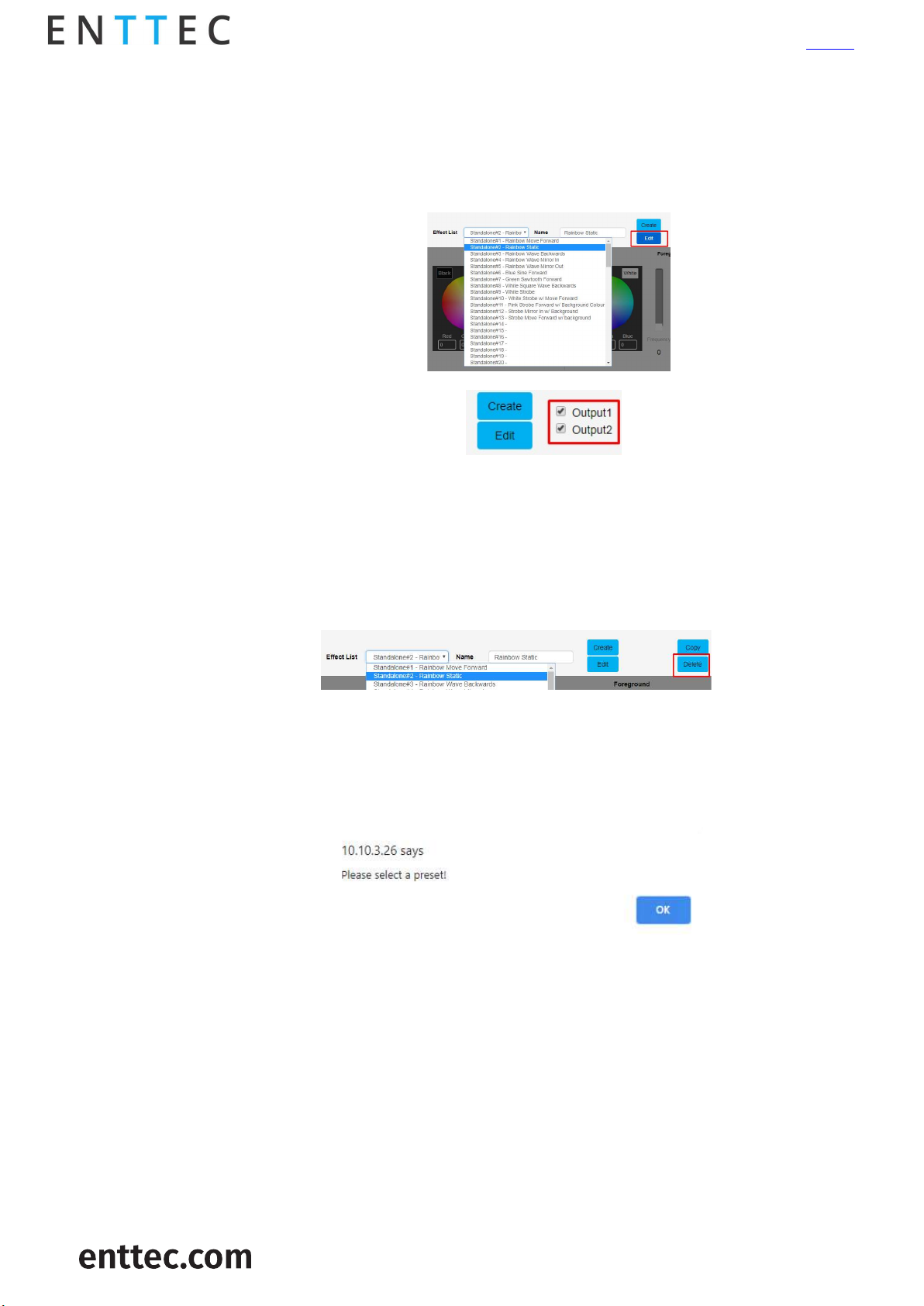
Editing a standalone effect
The OCTO allows the editing of any saved standalone effect.
Follow the steps below to edit a standalone:
1. Select the standalone to be edited and click on the Edit button.
2. Select an output to preview the standalone on by using the check boxes.
4. Edit the standalone
5. If the standalone previewed is to be preserved, click on Save Effect button
Deleting a standalone effect
Select the standalone to be deleted and press on the Delete button.
The standalone selected for each output will continue to play unless it is deleted; in this case, the
standalone directly above will be enabled at the output, which had the deleted show. If there is no
standalone above, no standalone will be output.
If a slot without a standalone is deleted the following message is displayed:
20 |
ID: 5928937
USER GUIDE - v1.0
Visit the ENTTEC website for
OCTO – 71521
the latest version
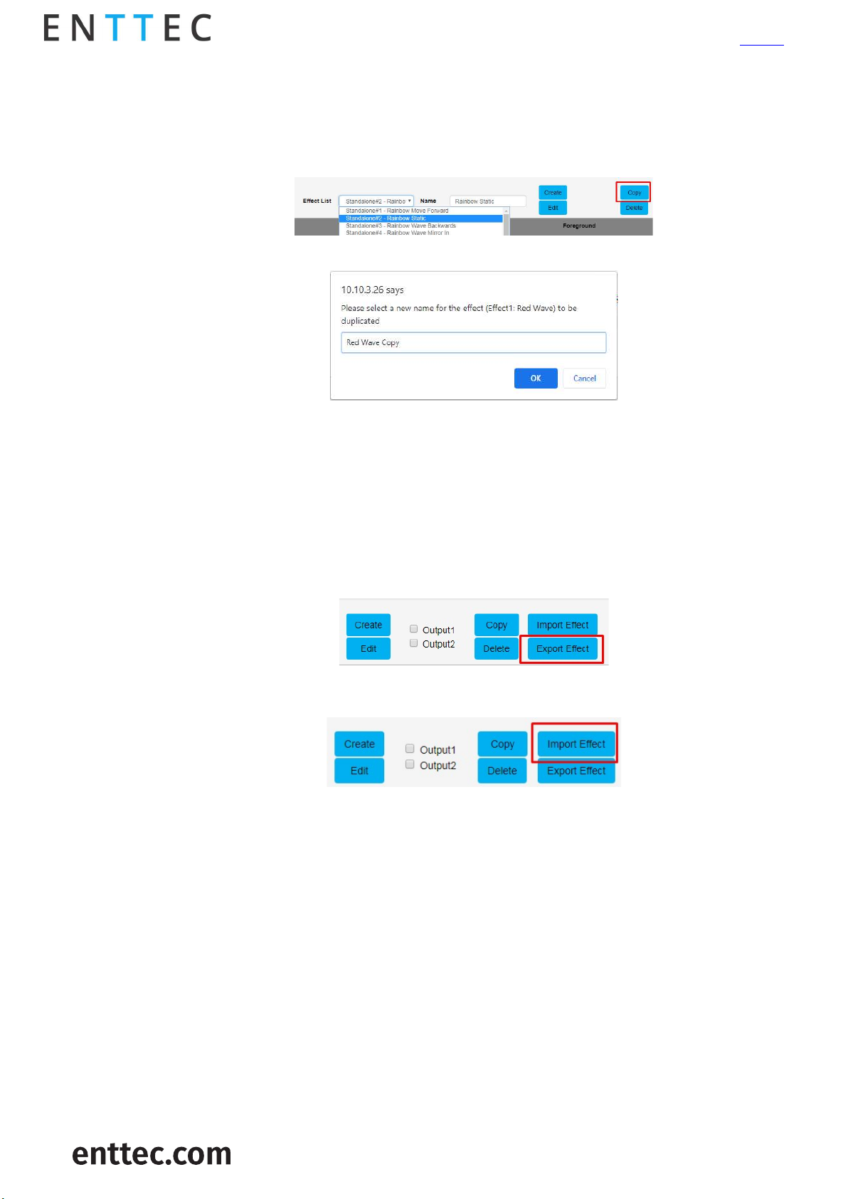
Copying a standalone show
The OCTO allows the copying of any saved standalone effect.
Follow the steps below to copy a standalone effect:
1. Select the effect to be copied and click on Copy button
2. Provide a new name for the copied standalone effect
Note:
The OCTO does not permit shows to be saved with the same name.
Importing and exporting a standalone list
The OCTO allows the import and export of all the standalone shows on the device.
Note:
The export file will include a list of all the standalone shows
Please click on Export Effect button to export the standalone shows
Please click on Import Effect button to import the standalone shows
21 |
ID: 5928937
USER GUIDE - v1.0

Network stats
The Network page shows statistics for the DMX protocol enabled.
Art-Net
The information provided is:
Poll packets received
Data packets received
Sync packets received
Last IP poll packets were received from
Last port data received from
OCTO – 71521
Visit the ENTTEC website for
the latest version
ESP
sACN
The information provided is:
Poll packets received
Data packets received
Last IP poll packets were received from
Last port data received from
The information provided is:
Data and sync packets received
Last IP packets were received from
Last port data received from
22 |
ID: 5928937
USER GUIDE - v1.0

KiNET
The information provided is:
Total packets received
Discover supply packets received
Discover ports packets received
DMXOUT packets
KGet packets
KSet packets
PORTOUT Packets
Set device name packet received
Set device IP packet received
Set universe packets received
Last IP received from
Last port data received from
OCTO – 71521
Visit the ENTTEC website for
the latest version
Updating firmware
It is strongly recommended that the OCTO is updated with the latest firmware, available on the
ENTTEC website. This firmware can be loaded to the driver through its web interface by carrying out
the following steps:
1. Browse and select the correct firmware version on your PC
2. Press the Update Firmware button
Once the firmware update is complete, the device will reboot while the web interface displays
the message shown in the image below
23 |
ID: 5928937
USER GUIDE - v1.0

Reset to factory defaults
Factory resetting the OCTO results in the following:
Resets the device name.
Enables DHCP.
Static IP Address reset (IP address = 10.(octet1).(octet2).(octet3) where the three bytes
are the last three bytes of the mac address in decimal)
Resets the gateway IP.
Netmask is set to 255.0.0.0
Restores standalone shows to factory default.
Direct mode is activated
Input protocol is set to Art-Net.
LED protocol is set as WS2812B.
Pixel color is set to RGB.
Both ports are set to output 4 universes. The start universe for output 1 is set as 0 and
output 2 as 4
Mapped pixels value is set to 680 pixels
DMX start address is set to 0
APA-102 global intensity set to maximum.
OCTO – 71521
Visit the ENTTEC website for
the latest version
Using web interface
The reset to defaults command can be found under the Settings tab of the OCTO.
Once the command is pressed, a pop-up would appear as shown in the image below:
Using the reset button
The reset button restores the network configuration of the OCTO to factory defaults:
To reset to factory defaults, the following procedure must be performed:
Power off the unit
Press and hold the Reset button.
While holding the Reset button, power up the unit, and keep holding the button for 3
seconds.
Release the Reset button once the status led starts blinking red.
24 |
ID: 5928937
USER GUIDE - v1.0

Tips and guidelines
I’m unable to connect to the OCTO web interface:
Ensure that the OCTO and your computer are on the same subnet
To troubleshoot:
1. Connect the OCTO directly to your computer using a Cat5 cable and power it on.
2. Give your computer a Static IP address (e.g.: 192.168.0.20)
3. Change computer Netmask to (255.0.0.0)
4. Open NMU and select the network adaptor connected to your OCTO.
5. If you have multiple networks (WiFi etc.), please try to disable all other networks
except the one OCTO is connected to.
6. Once NMU finds the OCTO, you will be able to open the device webpage and configure
it.
7. Factory Reset the device using the button if following the steps above and navigate to
the OCTO’s default IP if this did not resolve the issue.
OCTO – 71521
Visit the ENTTEC website for
the latest version
Is it possible to run pixel tapes and dots using different protocols and voltages at the same
time?
No, only one LED protocol can be selected to drive the output at a given time.
What is the minimum DC voltage for powering the OCTO?
The minimum DC voltage the OCTO requires to run is 4v.
25 |
ID: 5928937
USER GUIDE - v1.0

Servicing, inspection & maintenance
Servicing, inspection & maintenance should only be carried out by qualified technicians
familiar with all safety information within this document.
The OCTO has no user serviceable parts. If your installation has become damaged, parts should
be replaced.
Power down the entire system and ensure a method is in place to stop the system from
becoming energized during servicing, inspection & maintenance.
Key areas to examine during inspection:
o Ensure all connectors are mated securely and show no sign of damage or corrosion.
o Ensure all cabling has not obtained physical damage or been crushed.
o Check for dust or dirt build up on the OCTO and schedule cleaning if necessary.
o Dirt or dust buildup can limit the ability for the OCTO to dissipate heat and can lead to
damage.
OCTO – 71521
Visit the ENTTEC website for
the latest version
If deemed necessary for an OCTO to be replaced, it should be removed in a reverse order to the
installation process within this document.
The replacement OCTO should be installed in accordance with all steps within the installation guide.
To order replacement devices or accessories contact your reseller or message ENTTEC directly.
26 |
ID: 5928937
USER GUIDE - v1.0

Cleaning
Dust and dirt build up can limit the ability for the OCTO to dissipate heat resulting in damage. It’s
important that the OCTO is cleaned in a schedule fit for the environment it is installed within to
ensure maximum product longevity.
Cleaning schedules will vary greatly depending on the operating environment. Generally, the more
extreme the environment, the shorter the interval between cleaning.
Before cleaning, power down your system and ensure a method is in place to stop the system
from becoming energized until cleaning is complete.
Do not use abrasive, corrosive, or solvent-based cleaning products on an OCTO.
Do not spray OCTO’s or accessories. The OCTO is an IP20 product.
To clean an ENTTEC OCTO, use low-pressure compressed air to remove dust, dirt and loose particles.
If deemed necessary, wipe the OCTO with a damp microfiber cloth.
Visit the ENTTEC website for
OCTO – 71521
the latest version
A selection of environmental factors that may increase the need for frequent cleaning include:
o Use of stage fog, smoke or atmospheric devices.
o High airflow rates (i.e., in close proximity to air conditioning vents).
o High pollution levels or cigarette smoke.
o Airborne dust (from building work, the natural environment or pyrotechnic effects).
If any of these factors are present, inspect all elements of the system soon after installation to see
whether cleaning is necessary, then check again at frequent intervals. This procedure will allow you
to determine a reliable cleaning schedule for your installation.
27 |
ID: 5928937
USER GUIDE - v1.0

Package contents
OCTO
TS35 DIN Clip & 2* Torque T10 self-tapping screws
‘Read Me’ card
*Please note: the OCTO is not provided with a power supply.
Ordering information
Product SKU
OCTO 71521
Visit www.enttec.com to browse compatible pixel products and control system components.
For any sales requests, OEM enquiries or to give product feedback contact our team at
sales@enttec.com.
OCTO – 71521
Visit the ENTTEC website for
the latest version
Due to constant innovation, information within this document is subject to change any time.
28 |
ID: 5928937
USER GUIDE - v1.0
 Loading...