

Page 1
CV Driver MK2 Manual
50394
www.enttec.com
1
ID: 82325
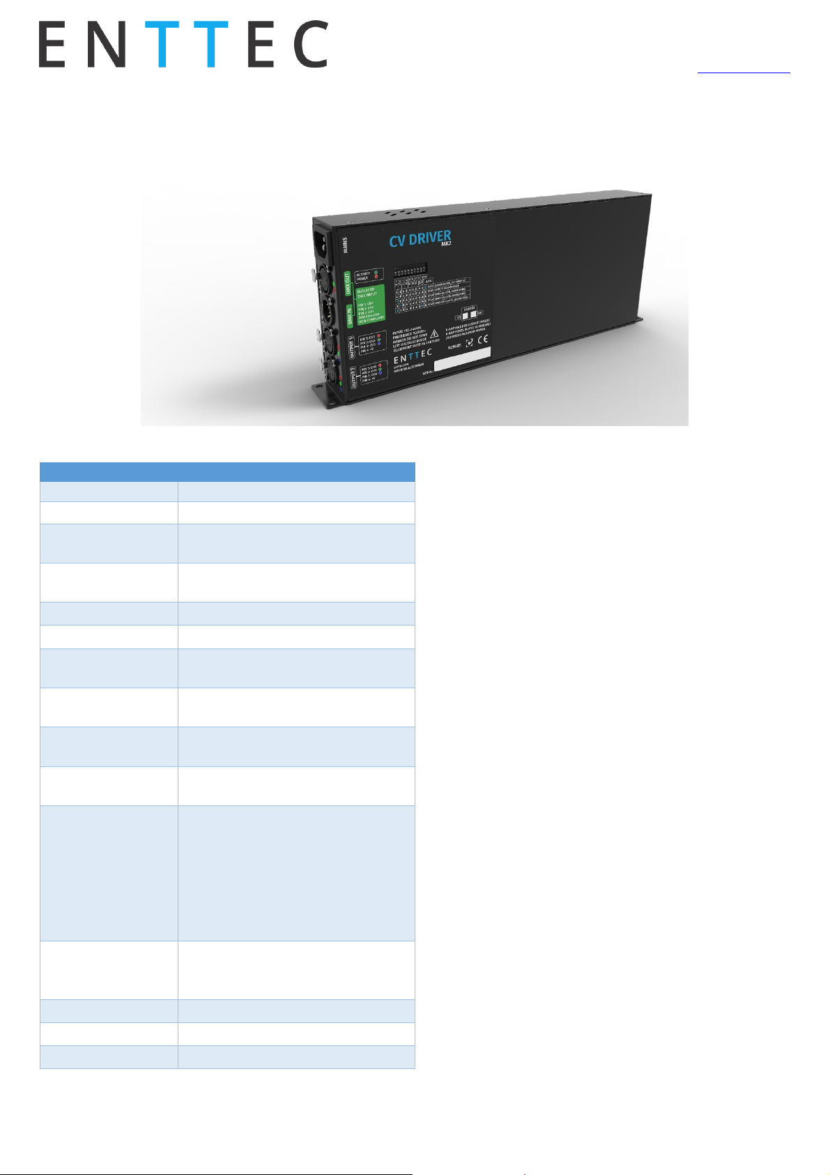
CV Driver MK2
Specifications
Features
• DMX512 Controllable and RDM Configurable
• Designed for driving LED strips through 6 high
power channels
• 12V and 24V DC output units available
• Easy addressing interface (physical switches and
RDM)
• Isolated DMX input
• 6 x 5 Amps constant voltage controllable outputs
• 250 watts total output power
• Fused outputs with surge protection
• Power, status and output LED indicators
• Stand-alone output sequences (if configured, no
external controllers required)
• Up to 8 units stackable using standard 19” modular
rack accessory (sold separately)
• Ideal for white or RGB LED Tapes
• Standard IEC mains input connector
• Auto-selectable Multi voltage mains input
Safety
• Make all the connections before you plug in the
main power
• Do not expose the ALEPH CV DRIVER to rain or
moisture, doing this will void the warranty
• Do not spill water or other liquids into or onto the
unit
• Check that the local power outlet matches that of
the required voltage (110 → 240V AC)
• Do not remove the cover whilst the unit is powered
• Never plug this unit in to a dimmer pack
Item
Value
Input Voltage
110 – 240V AC
Input Frequency
50/60Hz
Max total
Output Power
250 Watts
Max. Current
Per channel
5 Amps
Output Channels
6
Control Input
DMX512 & RDM E1.20
Personalities
3 DMX distributions: 6, 9 and 12
channels
Smart Dimming
14 bit internal dimming mapped to
8 bit S curve
Cooling Method
Forced air (temperature-regulated
for low noise)
Ambient Working
Temperature
5° to 35° C
Connectors
1x 5-Pin Male XLR for DMX input
1x 5-Pin Female XLR for DMX
output
2x 4-Pin Female XLR for channels
output
1x 3-Pin IEC C14 Male Socket
10Amps for mains
DMX Pinout
Pin1: Ground
Pin2: Data –
Pin3: Data +
Protection Rating
IP20
Net Weight
2.4 Kg
Shipping Weight
2.8 Kg
Page 2

CV Driver MK2 Manual
50394
www.enttec.com
2
ID: 82325
• Always be sure to mount this unit in an area
that will allow proper ventilation. Allow about 6”
(20 cm) between this device and a wall
• Make sure ventilation holes are clean and unob-
structed
• Do not attempt to operate this unit, if it be-
comes damaged
• This unit is intended for indoor use only
• Always mount this unit in safe and stable man-
ner
• Power-supply cords should be routed so that
they are not likely to be walked on or pinched
by items placed upon or against them, paying
particular attention to the point they exit from
the unit
• The driver should be situated away from heat
sources
• Make sure the unit is dry and there is no fluids
residue before powering the unit after cleaning
Firmware Update
Updating the firmware on ALEPH CV DRIVER requires an
ENTTEC USB Pro or a Pro Mk2 device plugged in to a PC
USB port and to the ALEPH CV unit through a standard 5
pin DMX cable.
Please download and install the latest firmware for
ALEPH CV from www.enttec.com website, connect the device to the unit, power it up and run the application.
To make sure the process has been successful and to
check the firmware version, please look at the “Software
Version ID” field using an RDM tool such us “ENTTEC RDM
Controller” software which can be downloaded for free
from ENTTEC website.
Thermal Management
ALEPH CV DRIVER (RevB onwards) has an in-built thermal
control system. It constantly monitors the hardware’s in-
ternal temperature and acts on the condition of overheating.
When internal temperature is higher than the limit, the
thermal control system will gradually lower the intensity
of all the connected LED strips or loads to cool down the
driver. Once the internal temperature is within the limit,
the driver will resume its normal operation.
The below graph shows a relationship between ambient
temperature versus output loads:
Surge Protections
ALEPH CV DRIVER has enhanced the surge protections for
all the output channels. This feature is designed to prevent
unexpected high voltages from permanently damaging the
channels. The chart below shows its operating parameters:
Please note: Surges are usually caused by installation issues such as unnecessary long cables, short-circuits, and
connecting the 4 pin XLR connector when driver is on etc. It
is highly recommended that users check the connections
before turning on the driver.
LED Status
The CV driver comes with eight LED indicators located in the
front panel. Two set of RGB LEDs on the bottom indicate the
channel activities. The red LED on top section indicates the
internal power supplies are working properly.
The top green LED next to the red LED indicates the driver
status and should be constantly flashing. Please refer to the
following table for information about current operating status:
Flashing Frequency
Unit Status
0.5 Hz
Idle
2 Hz
DMX/RDM received
8 Hz
Overheating
0
20
40
60
80
100
0 10 20 30 40 50
Load(%)
Amibient Temperature (° C)
Output Derating
Page 3

CV Driver MK2 Manual
50394
www.enttec.com
3
ID: 82325
Dip Switches Configuration
The ALEPH CV DRIVER counts with a 10 ways dip switch
which defines the behaviour of the unit, being switches #
1 to 9 the DMX start address and switch # 10 the mode.
The two modes defined by switch # 10 are called “Standard” and “Auto” where in standard mode the unit will
need an external DMX source to control the lights and in
auto mode the unit will generate pre-defined sequences
in stand-alone manner.
Please refer to the following table which describes how
to use the switches.
The binary number set in switches #1 to 9 will define the
sequence number. The following table shows some examples of pre-defined sequences.
RDM Capabilities
The ALEPH CV DRIVER has full RDM capabilities and you can
read/write them by using any standard RDM tool. The
“ENTTEC RDM Controller” software can be downloaded for
free from ENTTEC website and be used in combination with
a DMX USB PRO, RDM USB PRO or a PRO MK2 widget.
RDM addressing will be only available when all configuration switches are all set to OFF position.
Read only supported fields
• RDM Protocol Version
• Device Model ID
• Software Version ID
• Sensor Value
• DMX Footprint
• Sensor Count
• Manufacturer Label
• Supported Parameters Count
User configurable supported fields
• Lamp On Mode
o [OFF] Stays off until instructed
Auto Mode (Switch#10 is ON)
All
channels
OFF
All output
channels will
be dimmed
OFF
(Blackout)
CH1
full
intensity
CH1 output
will be driven
to full
intensity
CH4
full
intensity
CH4 output
will be driven
to full
intensity
CH6
full
intensity
CH6 output
will be driven
to full
intensity
All
channels
ON
All output
channels will
be driven to
full intensity
Standard Mode (Switch#10 is OFF)
RDM
(remote
addressing
)
When all the
address digits
(1 to 10) are
set to OFF the
DMX start
address must
be defined
through RDM
DMX (local
addressing
)
DMX start
Address is: 001
DMX (local
addressing
)
DMX start
Address is:
002
DMX (local
addressing
)
DMX start
Address is:
2+4=006
DMX (local
addressing
)
DMX start
Address is:
256+1=257
Page 4

CV Driver MK2 Manual
50394
www.enttec.com
4
ID: 82325
o [DMX] Strikes upon receiving DMX
o [ON] Strikes Auto at Power Up
• DMX Personality
o 8 Bit 6-Channel Mode
o 9-Channel Extended Mode
o 16 Bit 12-Channel Mode
• DMX Start Address
• PWM Adjustment
• Identify Device
• Factory Defaults
Channel Distribution (DMX
Personalities)
The CV Driver handles each DMX channel as an RDM subdevice, so you can assign independent addresses to each
channel which do not have to be consecutive. It is even
possible defining several channels to the same DMX address.
Changing Fuses
The ALEPH CV DRIVER has 6 Amps, UL glass fuses for protecting the outputs and can be changed by removing the metal
lid following these steps:
1- Un-power the unit. There are mains voltages inside, so
the unit must be never operated without the lid.
Strobe Rate
Value
Output Observed
000-010 →
Full Output depending on current
CH1- CH6 and Master Dimmer
channel.
011-252 →
Varies strobe frequency where 011
is the lowest and 252 the highest
(keeps the colour and master dimmer values from the other channels)
253-255 →
Full Output depending on current
CH1- CH6 and Master Dimmer
channels
Master Dimmer
Value
Output Observed
000 →
All outputs will be OFF (dimmed to
0%)
255 →
Full Output (100%) depending on
current CH1-CH6 and Strobe frequency channels.
000-255 →
Dims all channels merging them
with the current CH1-CH6 and
Strobe rate channels. 000 is 0%
and 255 is 100% intensity.
Strobe Duration
Value
Output Observed
000 →
Shortest time that the LED stays
on while strobing
255 →
Longest time that the LED stays on
while strobing
Fuses Specifications
Size
5 x 20 mm
Current Rating
6 Amps
Voltage Rating
125V
Response time
Fast
Page 5

CV Driver MK2 Manual
50394
www.enttec.com
5
ID: 82325
2- Detach the metal lid by removing the 10 Philips type
screws. Please note that there is a wire running from the
base to the lid which need to be watched during the procedure:
3- Locate and change the desired fuse in the main controller board using one of the diagrams below:
4- Place the lid back and the unit will be ready to be repowered.
Dimensions
The ALEPH CV DRIVER is designed to fit the modular rack accessory (sold separately) which allows stacking up to 8
units.
Due to continuous improvements and innovations of all
ENTTEC products, specifications and features are subject to
change without notice.
Revision Log
Revision
Description
Aleph 1 CV Driver
Constant voltage driver with
UL glass fuses for each of the
six channels
Aleph CV Driver MK2
Constant Voltage driver with
a fuse for each output
Stackable Modular Rack (Accessory)
The modular rack (sold separately) allows up to 8 ALEPH CV
DRIVER units to be stacked up using only 3 standard rack
units (3RU). Also has an in-built fan at the rear side.
Page 6

CV Driver MK2 Manual
50394
www.enttec.com
6
ID: 82325
Screw Terminal Output (Accessory)
The converter from 4 pin XLR to screw terminal (sold separately) allows easy installation by using a flat screw
driver, avoiding the need of wiring and soldering.
Ordering Information
The ALEPH CV DRIVER MK2 and compatible products can be
ordered from our website or through your ENTTEC dealer
using the following part numbers. Different voltage and
protocol units are made under special order (please contact
us).
Part Number
Description
73520
ALEPH CV DRIVER MK2 (24V)
73522
ALEPH CV DRIVER MK2 (12V)
73526
XLR 4PIN TO SCREW TERMINAL
OUTPUT CONVERTER
73530
A1 - 8 WAY CV RACK (240V AC)
 Loading...