

Page 1
Aleph2 ET DX4 Manual
50952
www.enttec.com
1
ID: 1552792
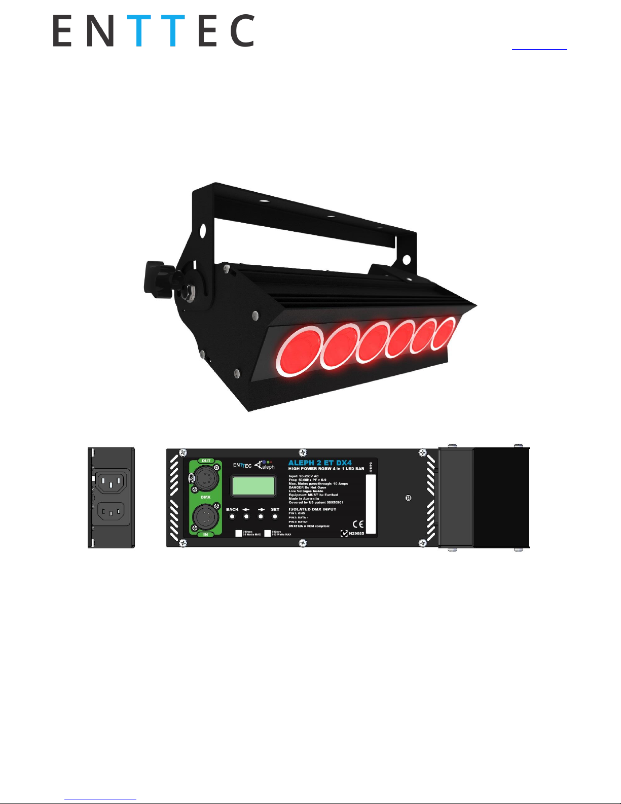
ALEPH2 ET DX4
4 colour HIGH POWER LED light BAR
300mm/600mm
Back Panel
Please make sure the Power pass-through current does not exceed 10 Amps
Features
Strong aluminium chassis with small profile
DMX512 Controllable and RDM Configurable
Can use up to 8 DMX channels, depending on
configuration
Snapshots: 64 fully user recordable slots, 25 dif-
ferent pre-loaded stand-alone colours
16-bit or Smart 8-bit LED dimming
Strobe Mode with controllable frequency from DMX
Fan-less smart heat management
Easy addressing and configuration interface
180° Ajustable mounting bracket
Changeable diffuser using holder accessory (sold
separately)
Page 2
Aleph2 ET DX4 Manual
50952
www.enttec.com
2
ID: 1552792
Cleaning
It is important to clean the ALEPH2 ET DX4 to maintain a
long service life. Make sure the unit is unplugged before
you attempt any cleaning.
Surface dust should be removed with an air com-
pressor, please make sure you do not blow compressed air directly inside the unit.
Optics can be cleaned with a glass cleaner or IPA
with a soft cloth
Make sure the unit is dry and there is no cleaning
fluid residue before powering the unit after
cleaning.
Safety
Do not expose the ALEPH2 ET DX4 to rain or mois-
ture, doing this will void your warranty.
Do not spill water or other liquids into or onto
your unit.
Do not look directly into the LEDs, doing so may
damage your eyes.
Check that the local power outlet matches the re-
quired voltage (120 → 240V AC)
Make all the connections before you plug in the
main power.
Do not remove the cover under any condition.
There are no user serviceable parts inside.
Never operate this unit when its cover is re-
moved.
Never plug this unit in to a dimmer rack.
Always be sure to mount this unit in an area that
will allow proper ventilation. Allow at least 20 cm
between this device and a wall.
Make sure ventilation holes are clean and unob-
structed.
Do not attempt to operate this unit, if it becomes
damaged.
Always mount this unit in a safe and stable man-
ner.
Power-supply cords should be routed carefully.
The unit should be situated away from heat
sources
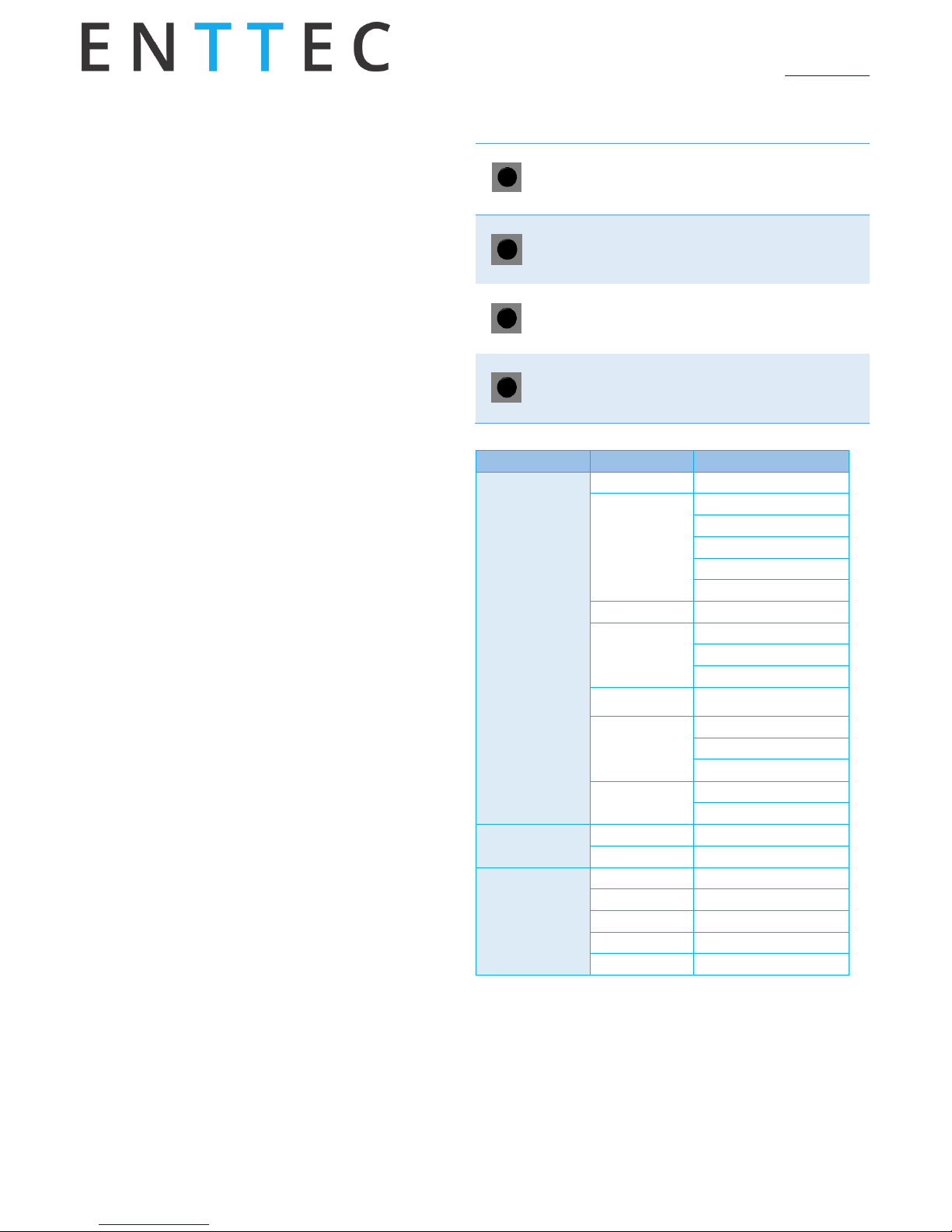
Control Panel
After powering up, the current firmware version is displayed, followed by the DMX Start Address. The unit can
be configured by using the 4 buttons under the display
as follows.
BACK
-If pressed while address is being displayed:
It activates the back-light and goes to Main Menu
-If pressed while setting a menu:
It takes you to the previous level without changing anything
←
-Scrolls down when navigating the menu
-Decreases the value displayed when setting a parameter
-Hold the button for a few seconds to fast scroll down
→
-Scrolls up when navigating the menu
-Increases the value displayed when setting a parameter
-Hold the button for a few seconds to fast scroll up
SET
-Confirms the displayed value
-Activates the displayed function or
-Opens the next menu
Main Menu
Level 1
Level 2
Setup
DMX Address
Values: 001 to 512
Personality
1 – 8bit RGBW Mode
2 – 8bit RGB Mode
3 – 16bit 8ch Mode
4 – 16bit 6ch Mode
5 – Extended 7ch Mode
Pre-sets
Values: 01 to 64
Lamp On Mode
OFF
DMX
ON
PWM Frequency
Values:
500, 1500 or 2000
Back-light
NORMAL
ON
OFF
Factory Defaults
YES
NO
Temperature
LED TEMP
CPU TEMP
Test
LED 1 LED 2
LED 3
LED 4
ALL LEDs
DMX Address Menu
The DMX start address is the most important parameter to
be defined when setting up your lights. By default the fixture will be set to 001.
Page 3

Aleph2 ET DX4 Manual
50952
www.enttec.com
3
ID: 1552792
The addressing will depend on the current selected personality. For example if the light is set to RGBAW mode (5
channels), the DMX address range will be 001 – 508.
Personality Menu
The ALEPH2 ET DX4 has five different personalities or operational modes, which can either be selected remotely
from any standard RDM controller tool or locally using
the control panel. The light behaves differently in each
mode, since the DMX channel distribution changes according to the desired working personality. Set the desired personality before patching your lights in any lighting desk or control system.
1 – 8BIT RGBW MODE (4 Channel)
This basic mode will turn the DX4 into a 4 channel light,
allowing to drive each available colour as an independent dimmer. Each DMX channel uses 8 bits resolution
where 000 is OFF, 255 is Full intensity, as described in the
following chart.
1st Channel
2nd Channel
3rd Channel
4th Channel
RED GROUP
GREEN GROUP
BLUE
GROUP
WHITE
GROUPS
2 – 8BIT RGB MODE (3 Channel)
As some lighting control systems do not support RGBW
lights, we have implemented a RGB mode so the fixture
can be used with any controller. Each DMX channel uses
8 bits resolution where 000 is OFF, 255 is Full intensity, as
described in the following chart.
1st Channel
2nd Channel
3rd Channel
RED GROUP
GREEN GROUP
BLUE GROUP
3 - 16BIT (8 CHANNEL) MODE
This mode will allow you to drive each colour using 16
bits resolution; setting the values from one of the 8 DMX
channels from 000 to 255 where the first channel of each
group will be (HIGH) and the following channel the (LOW)
one, as described in the following chart.
1st
Channel
2nd
Channel
3rd
Channel
4th
Channel
5th
Channel
6th
Channel
RED
GROUP
(HIGH)
RED
GROUP
(LOW)
GREEN
GROUP
(HIGH)
GREEN
GROUP
(LOW)
BLUE
GROUP
(HIGH)
BLUE
GROUP
(LOW)
7th
Channel
8th
Channel
WHITES
(HIGH)
WHITES
(LOW)
This personality gives the user full control on the output
dimming, so any colour combination can be generated.
4 - 16BIT (6 CHANNEL) MODE
This mode will allow you to only drive RGB colour using 16
bits resolution; setting the values from one of the 6 DMX
channels from 000 to 255 where the first channel of each
group will be (HIGH) and the following channel the (LOW)
one, as described in the following chart.
1st
Channel
2nd
Channel
3rd
Channel
4th
Channel
5th
Channel
6th
Channel
RED
GROUP
(HIGH)
RED
GROUP
(LOW)
GREEN
GROUP
(HIGH)
GREEN
GROUP
(LOW)
BLUE
GROUP
(HIGH)
BLUE
GROUP
(LOW)
5 - EXTENDED (7 CHANNEL) MODE
This extended mode offers a wide variety of output effects,
turning the ALEPH2 ET DX4 into a very versatile unit, using 7
DMX channels, as described in the following chart.
1st Channel
2nd Channel
3rd Channel
4th Channel
RED GROUP
GREEN GROUP
BLUE
GROUP
WHITE
GROUPS
5th Channel
6th Channel
7
th
Channel
STROBE
DURATION
STROBE
FREQUENCY
MASTER
DIMMER
COLOUR GROUP INTENSITY (CH1-CH4) operate as described
in the RGBW personality plus they can be modified or affected by the strobe function or master dimmer channel, as
described further in this section.
STROBE DURATION (CH5) this channel works in conjunction
with the strobe frequency from CH6. II will only take effect
if channel 6 is greater than 10.
It defines the duration of the ON state and linearly increases the time from 2.5 milliseconds when 000 to 650 milliseconds when 255.
NOTE: Strobe duration time must be lower than Strobe frequency for flashing. If duration time is equal or greater than
frequency, the light will be continuously ON.
STROBE FREQUENCY (CH6) will turn the ALEPH2 ET DX4 bar
into a versatile multi-colour strobe with user adjustable frequency. The strobe feature can be activated by setting the
channel to a value between 011 and 255. In the same range,
the strobe frequency can be adjusted by varying the channel value, with 011 the lowest frequency (about 0.3 flashes
per second) and 255 the highest one (25 flashes per second).
The strobe channel can be used in conjunction with all the
other channels, so you can change the current output colour or the master intensity whilst strobing at the selected
frequency, all at the same time.
Page 4

Aleph2 ET DX4 Manual
50952
www.enttec.com
4
ID: 1552792
MASTER DIMMER (CH7) drives the master intensity of all
the outputs. 000 the lowest intensity 0% (light will be
OFF, regardless of other channel values) and 255 the
highest, allowing 100% (maximum).
Presets Menu
The Aleph2 ET DX4 has 64 available slots where the user
can record custom colours from DMX. These can later be
activated from the menu. Presets turn the ET into a
stand-alone fixture, where 64 different colours can easily
be triggered on-site, without the need of DMX.
It is also possible to record user personalised Presets on
any of the 64 memory slots, overwriting the default ones.
RECORDING CUSTOM PRESETS:
To record your own colours, please scroll to the desired
slot (from 01 to 64), feed the desired data through the
DMX port until you are happy with the look. Then press
the SET key to overwrite the preset.
Pre-Set
Factory Default
Colour
01
All channels OFF (Default on Start-Up)
02
Red
03
Green
04
Blue
05
Neutral White
06
RGB Yellow
07
RGB Purple
08
RGB Cyan
09
5000K White
10
6000K White
11
6500K White
12
Pink
13
Pink1
14
Violet
15
Dark Violet
16
Crimson
17
Royal Blue
18
Aqua Marine
19
Slate Blue
20
Turquoise
21
Lime
22
Golden Yellow
23
Orchid
24
Salmon
25
Coral
26 to 64 slots are available for user custom colours
IMPORTANT NOTES:
When the light is powered on, it will automatically take preset 01 as the default power on value, if the Lamp On Mode
setting is ON. This feature is handy for the user to set up the
desired colour combination for the fixture to start every
time it is powered up.
Note that the strobe feature is NOT a supported preset.
Any incoming DMX data will override the Presets, so ensure
that there is no DMX data coming in before navigating this
menu intending to playback the different colours.
Running the Factory Defaults RDM command will restore all
the Presets to the original values and user recorded Presets
will not be recoverable.
Lamp On Mode Menu
This setting instructs the DX4 what to do after a power up
sequence.
If DMX or OFF settings are chosen, the DX4 will stay off and
will wait for DMX instructions.
When Lamp On Mode = ON the DX4 will power up and then
output whatever look has been recorded in slot 01 of the
Presets. Please notice that any incoming DMX will override
this preset, as DMX takes the highest precedence.
PWM Frequency Menu
The PWM driving frequency can be adjusted. This might
have an impact on the way some cameras respond to the
light emitted by the A2 ET DX4.
Backlight Menu
The NORMAL setting will turn the display green back light
on after any key operation. It will turn it off after a 15 seconds of in-activity. The ON setting will keep the back light
always on. The OFF setting will keep the back light always
off, regardless of any operation.
Factory Defaults Menu
Running the Factory default sequence will reset all the user
configurable parameters, including DMX address, presets,
Personality, Lamp On mode, Etc.
Page 5

Aleph2 ET DX4 Manual
50952
www.enttec.com
5
ID: 1552792
Temperature Menu
This menu shows the current fixture temperature in degrees Celsius.
LED and CPU operating temperatures can be monitored
from the control panel as well as RDM.
Test Menu
Using this menu you can test every group of LEDS in the
DX4 fixture. The LEDs will turn on at full power, so avoid
looking at the light directly when performing the test.
Firmware Version
Indicates the current firmware version installed in the
fixture. Please check ENTTEC website for latest firmware
version.
Firmware Update
Updating the firmware of the ALEPH2 ET DX4 requires an
ENTTEC USB Pro or a Pro Mk2 usb interface plugged in to
a PC USB port. Connect the USB PRO to the ET through a
standard 5 pin DMX cable.
Please download and install the RDM Controller App
from www.enttec.com website, connect the widget to the
unit, power it up and run the application.
To make sure the process has been successful, confirm
the firmware version has changed by looking at the “Software Version ID” RDM field or navigate to the Firmware
Version menu using the control panel.
RDM Capabilities
The ALEPH2 ET DX4 supports RDM features and any RDM
Controller can be used to configure it using RDM. The free
“ENTTEC RDM Controller” App can be downloaded from
ENTTEC website and be used in combination with a DMX
USB PRO or a PRO MK2 widget. The supported RDM parameters are:
Read only fields
Device Info
Software Version ID
Supported Parameters
Parameters Description
DMX Personality Description
Sensor Value (temperature x 2)
Sensor Definition
Boot Software Version
Manufacturing Label
Device Label
Status Messages
User configurable fields
Identify Device
DMX Start Address
PID_8001: Master faders
DMX Personality
Factory Defaults
Lamp On Mode
Reset Device
Capture Preset
Preset Playback
Please note that DMX Personality, DMX Start Address, Factory Defaults, Lamp On Mode and Presets fields can also be
configured from the menu interface at the back of the light.
Specifications
Due to continuous improvements and innovations of all
ENTTEC products, specifications and features are subject to
change without notice.
Item
300mm
600mm
Input Voltage
110 – 240V AC
Input Frequency
50/60Hz
Maximum Power Consumption
55 Watts
110 Watts
Light Output (all on)
1460 lm
2920 lm
Minimum turn on
level(DMX=1)
Red:0.1lm
Red:0.2lm
Green:0.9lm
Green:1.8lm
Blue:0.36lm
Blue:0.72lm
White:1.7lm
White:3.4lm
CRI
80
CREE XM-L Color Leds Quantity
6
12
Colours
Red, Green, Blue, Neutral
White
Diffuser
Additional diffusers sold sep-
arately
Beam Angle
40°
Control Input
DMX512 & RDM E1.20
Weight (Kg)
3.7
4.9
Weight (Pounds)
8.2
10.8
Cooling Method
Convection
Ambient Temperature
5° to 50° C
Surface Operating
67°C at steady state
Temperature
(full intensity output and
Ta=45°C)
Maximum Surface
70°C
Temperature
Error mode (10% output)ena-
bles if T>70°C recovers after
5°C drop
Ingress Protection Rating
IP20
Page 6

Aleph2 ET DX4 Manual
50952
www.enttec.com
6
ID: 1552792
Connectors
1x 5-Pin Male XLR for DMX in-
put
1x 5-Pin Female XLR for DMX
output
1x IEC C13/C14 IN/OUT Socket
for mains
Dimensions
Item A B C D
300mm
340mm
400mm
100mm
3
600mm
640mm
700mm
200mm
3
Color Gamut
Registration
Please register your ENTTEC product to get latest software
updates and to validate your warranty. To register, please
visit enttec.co m/r egi ster
Ordering Information
ALEPH2 ET DX4 and compatible products can be ordered
from our website or through your ENTTEC dealer using the
following part numbers.
Different voltage and protocol units are made under special
order (please contact us).
Part Number
Description
73805-600
ALEPH2 ET DX4 LED BAR 41DEG 600MM
73805-300
ALEPH2 ET DX4 LED BAR 41DEG 300MM
73806-600
ALEPH2 ET DX4 LED BAR 22DEG 600MM
73806-300
ALEPH2 ET DX4 LED BAR 22DEG 300MM
73807-600
ALEPH2 ET DX4 LED BAR 31DEG 600MM
73807-300
ALEPH2 ET DX4 LED BAR 31DEG 300MM
Email: sales@en ttec.co m
Website: www.enttec.com
 Loading...