

Page 1

Ditec TOP603H / TOP903H
Automation for sectional
doors (translation of the original instructions)
www.ditecentrematic.com
IP2179EN
Technical Manual
Page 2

52
IP2179EN - 2015-11-24
Contents
Subject Page
1. General safety precautions
TOP603H - TOP903H
54
General safety precautions for the user 55
Machinery Directive 56
2. Declaration of Incorporation 57
3. Technical specifications 58
3.1 Operating instructions 58
3.2 Possible applications with general sectional doors 59
3.3 Possible applications with ENTREMATIC sectional doors 60
4. Dimensions 61
5. Standard installation 62
6. Main components 63
7. Assembly guide 64
8. Tensioning the belt 65
9. Assembling the automation 66
10. Mechanical installation 67
11. Assembling and fastening the arm 68
12. Installing the adapter for TOPSB tilting doors 70
13. Electrical connections TOP603H
TOP603H
71
13.1 Wiring the accessories 72
13.2 Commands TOP603H 74
13.3 Outputs and accessories 74
14. Commands and indications 75
14.1 Deleting the memorised stroke values 75
14.2 Restoring the factory settings 75
15. Self-learning of the stroke TOP603H 76
16. Memorising / Deleting remote controls 77
17. Adjusting the parameters 77
18. Parameters 78
19. Electrical connections TOP903H
TOP903H
81
19.1 Wiring the accessories 82
19.2 Commands TOP903H 84
19.3 Outputs and accessories 84
20. Commands and indications 85
20.1 Deleting the memorised stroke values 85
20.2 Restoring the factory settings 85
Page 3
53
IP2179EN - 2015-11-24
Key
i
This symbol indicates instructions or notes regarding safety, to which special attention must be paid.
This symbol indicates useful information for the correct functioning of the product.
21. Self-learning of the stroke TOP903H
TOP903H
86
22. Memorising / Deleting remote controls 87
23. Adjusting the parameters 88
24. Parameters 89
25. Troubleshooting
TOP603H
TOP903H
93
25.1 Alarms 94
26. Maintenance 95
Replacing the fuse 95
Replacing the courtesy light 95
Replacing the remote control battery 96
Page 4
54
IP2179EN - 2015-11-24
1. General safety precautions
This installation manual is intended for qualified personnel only.
Installation, electrical connections and adjustments must be performed by qualified personnel, in accordance with Good Working Methods and in compliance with the current regulations.
Read the instructions carefully before installing the product.
Incorrect installation could be dangerous.
The packaging materials (plastic, polystyrene, etc.) should not be discarded in the environ-
ment or left within reach of children, as they are a potential source of danger.
Before installing the product, make sure it is in perfect condition.
Do not install the product in explosive areas and atmospheres: the presence of inflammable
gas or fumes represents a serious safety hazard.
Before installing the motorisation device, make all the necessary structural modifications to
create safety clearance and to guard or isolate all the crushing, shearing, trapping and general
hazardous areas.
Make sure the existing structure is up to standard in terms of strength and stability. The motorisation device manufacturer is not responsible for failure to observe Good Working Methods
when building the frames to be motorised, or for any deformations during use.
The safety devices (photocells, safety edges, emergency stops, etc.) must be installed taking
into account the applicable laws and directives, Good Working Methods, installation premises,
system operating logic and the forces developed by the motorised door or gate.
The safety devices must protect against crushing, cutting, trapping and general danger areas
of the motorised door or gate.
Display the signs required by law to identify hazardous areas.
Each installation must bear a visible indication of the data identifying the motorised door
or gate.
When necessar y, connect the motorised door or gate to an effective ear thing system that complies with the current safety standards.
During installation, maintenance and repair operations, cut off the power supply before opening
the cover to access the electrical parts.
The automation protection casing must be removed by qualified personnel only.
The electronic parts must be handled using earthed antistatic conductive arms. The
manufacturer of the motorisation declines all responsibility if component parts not compatible with safe and correct operation are fitted.
Only use original spare parts when repairing or replacing products.
The installer must supply all information concerning the automatic, manual and emergency operation of the motorised door or gate, and must provide the user with the operating instructions.
Failure to respect the information given in this manual
may cause personal injury or damage to the device.
Keep these instructions for future reference
Page 5

55
IP2179EN - 2015-11-24
These precautions are an integral and essential part of the product
and must be supplied to the user.
Read them carefully since they contain important information on safe
installation, use and maintenance.
These instructions must be kept and forwarded to all possible future
users of the system.
This product must only be used for the specific purpose for which it
was designed.
Any other use is to be considered improper and therefore dangerous.
The manufacturer cannot be held responsible for any damage caused
by improper, incorrect or unreasonable use.
Avoid operating in the proximity of the hinges or moving mechanical
parts. Do not enter within the operating range of the motorised door
or gate while it is moving.
Do not obstruct the motion of the motorised door or gate, as this may
cause a dangerous situation.
The motorised door or gate may be used by children over the age of 8
and by people with reduced physical, sensorial or mental abilities, or
lack of experience or knowledge, as long as they are properly supervised
or have been instructed in the safe use of the device and the relative
hazards.
Children must be supervised to make sure they do not play with the
device, nor play/remain in the sphere of action of the motorised door
or gate.
Keep remote controls and/or any other command devices out of the
reach of children, to avoid any accidental activation of the motorised
door or gate.
The self-adhesive label (supplied) highlighting the risk of children getting trapped must be attached in a clearly visible place.
In the event of a product fault or malfunction, turn off the power supply
switch. Do not attempt to repair or intervene directly, and contact only
qualified personnel.
Failure to comply with the above may cause a dangerous situation.
Any repairs or technical interventions must be carried out by qualified
personnel.
Cleaning and maintenance work must not be carried out by children
unless they are supervised.
General safety precautions for the user
Page 6

56
IP2179EN - 2015-11-24
To ensure that the system works efficiently and correctly, the manufacturer’s indications must be complied with and only qualified personnel
must perform routine maintenance on the motorised door or gate. In
particular, regular checks are recommended in order to verify that the
safety devices are operating correctly.
All installation, maintenance and repair work must be documented and
made available to the user.
Only lock and release the door wings when the motor is switched off.
Do not enter within the operating range of the wing.
To dispose of electrical and electronic equipment correctly, users
must take the product to special "recycling centres" provided by
the municipal authorities.
Machinery Directive
Pursuant to the Machinery Directive (2006/42/EC), the installer who motorises a door or gate has
the same obligations as the manufacturer of machinery and as such must:
- prepare the technical data sheet which must contain the documents indicated in Annex V of the
Machinery Directive;
(The technical data sheet must be kept and placed at the disposal of competent national authori-
ties for at least ten years from the date of manufacture of the motorised door);
- draw up the EC Declaration of Conformity in accordance with Annex II-A of the Machinery Directive and deliver it to the customer;
- affix the EC marking on the motorised door or gate, in accordance with point 1.7.3 of Annex I of
the Machinery Directive;
- ensure compliance of the motorised door or gate with safety regulations, by installing the necessary safety devices.
Page 7

57
IP2179EN - 2015-11-24
We:
Entrematic Group AB
Lodjursgatan 10
SE-261 44 Landskrona
Sweden
declare under our sole responsibility that the type of equipment :
The TOP603H and TOP903H automation with remote control for residential garages complies
with the following directives:
2004/108/EC Electro Magnetic Compatibility Directive (EMCD)
2002/95/EC Restriction of the use of Hazardous Substances in electrical and electronic
equipment (RoHS)
1999/5/EC Radio and Telecommunications Terminal Equipment Directive (R&TTE)
2006/42/EC Machinery Directive (MD), in particular the following essential health and safety
requisites:
1.1.2,1.1.3,1.2.1,1.2.3,1.2.4,1.2.6,1.3.2,1.3.4,1.5.1,1.5.2,1.5.3,1.5.8,1.5.9,1.5.10,1.5.11,1.6.3,1.7.3,1.7.4
Technical documentation for safe integration is provided
Harmonised European standards which have been applied:
EN 13849-1 EN 61000-6-2 EN 61000-6-4 EN 60204-1 EN 60335-1
Other standards or technical specifications, which have been applied:
EN 60335-2-95 EN 60335-2-103 EN 55014
EC type examination or certificate issued by a notified or competent body (for full address, please
contact Entrematic Group AB) concerning the equipment:
The manufacturing process ensures the compliance of the equipment with the technical file.
The manufacturing process is regularly checked by third parties.
The equipment must not be used until the installation company has declared that the final installed door system complies with Machinery Directive 2006/42/EC.
Compilation of technical file:
Marco Pietro Zini E-mail: [email protected]
Entrematic Group AB
Lodjursgatan 10
SE-261 44 Landskrona
Sweden
Place Date Signature Position
Landskrona 2014-07-31 Marco Pietro Zini President Entrance Automation
Declaration of Incorporation
Page 8
58
IP2179EN - 2015-11-24
3. Technical specifications
3.1 Operating instructions
Service class: 3 (minimum 10-5 years of working life with 30-60 cycles per day).
Applications: FREQUENT (for multi-family type entrances or small apartment blocks with frequent
vehicle access).
- The performance characteristics refer to the recommended weight (approx. 2/3 of the maximum
permitted weight). When used with the maximum permitted weight, a reduction in the above
mentioned performance levels can be expected.
- The service class, running times and number of consecutive cycles are merely indicative, having
been statistically determined under average operating conditions and therefore not necessarily
applicable to specific conditions of use.
- Each automatic entrance has variable elements such as friction, balancing and environmental
factors, all of which may substantially alter the performance characteristics or working life of
the entrance itself or its components (including the automatic devices). The installer should
apply suitable safety conditions for each particular installation.
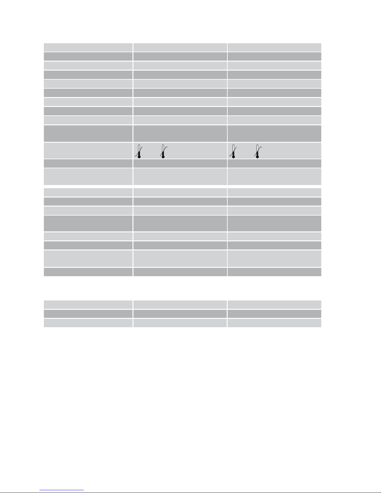
Ditec TOP603H Ditec TOP903H
Power 230V~, 50/60 Hz 230V~, 50/60 Hz
Power 140W 170W
Thrust 600 N 1000 N
Opening speed 210mm/s 210mm/s
Closing speed 140mm/s 140mm/s
Maximum door area (*) 9.5 m² 17.3 m²
Maximum door weight 116kg 210kg
Service class 3 - FREQUENT 3 - FREQUENT
Intermittence
S2 = 5 min
S3 = 25%
S2 = 5 min
S3 = 25%
Ambient temperature
-20°C +50°C -20°C +50°C
Degree of protection IP20 IP20
Acoustic pressure emitted at a
distance of 2m
≤69 dB (A) ≤69 dB (A)
Control panel TP603EL TP903EL
Control panel fuse 1.6A T (delayed) 2x1.6A T (delayed)
Motor power supply 24V= / 9.5A 24V= / 10.5A
Power supply for accessories
24V= / 0.3A max 2 s
24V= / 0.08A continuous
24V= / 0.3A max 2 s
24V= / 0.08A continuous
Radio frequency 433.92 MHz 433.92 MHz
Maximum remote control range 15-50m 15-50m
Remote control functions /
programmable keys
50 50
Courtesy light E14 max 60W E14 max 60W
TOP803T3 guide TOP803T4 guide
Max. carriage stroke 2890 +/- 25mm 3978 +/-25mm
Maximum height of door 2450mm 3500mm
(*) N.B.: the maximum door area has been calculated using a specific door weight of 12 kg/ m² (most common).
For values <12 kg/m² the maximum area in m² is larger. For values >12 kg/m² the maximum area in m² is
smaller (see graphs in par. 3.2 and 3.3)
Page 9

59
IP2179EN - 2015-11-24
3.2 Possible applications with general sectional doors
1500
2000
2500
3000
3500
1800 2000 2200 2400 2600 2800 3000 3200 3400 3600 3800 4000 4200 4400 4600 4800 5000 5200 5400 5600 5800 6000
Door height H (mm)
Door width W (mm)
Maximum dimensions of door - TOP603H (Max. door weight = 116 kg)
10
12
14
Weight of door
per square
metre
(kg/m
2
)
H
Max
TOP803T3 = 2450 mm
H
Max
TOP803T4 = 3500 mm
1500
2000
2500
3000
3500
1800 2000 2200 2400 2600 2800 3000 3200 3400 3600 3800 4000 4200 4400 4600 4800 5000 5200 5400 5600 5800 6000
Door height H (mm)
Door width W (mm)
Maximum dimensions of door - TOP903H (Max. door weight = 210 kg)
10
12
14
Weight of door
per square
metre
(kg/m
2
)
H
Max
TOP803T3 = 2450 mm
H
Max
TOP803T4 = 3500 mm
Page 10
60
IP2179EN - 2015-11-24
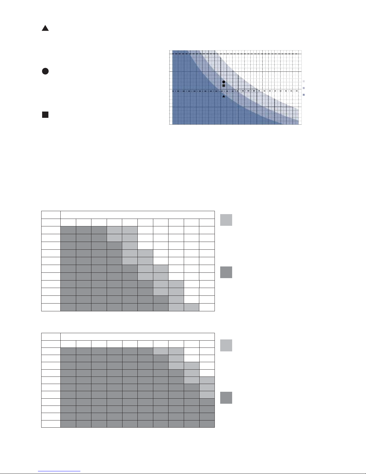
3.3 Possible applications with ENTREMATIC sectional doors
Width
Height 1800 2000 2500 3000 3500 4000 4500 5000 5500 6000
3150
2965
2815
2795
2639
2483
2538
2250
2125
2000
1900
Width
Height 1800 2000 2500 3000 3500 4000 4500 5000 5500 6000
3150
2965
2815
2795
2639
2483
2538
2250
2125
2000
1900
TOP603H
TOP903H
Dimensions allowed for Style
Comfort series doors with
Plain design (0.6 mm sheet
and above)
Dimensions allowed for Style
Comfort series doors with
Plain design (0.6 mm sheet
and above)
Dimensions allowed for
Style Basic and Style Comfort series doors with Cortex
and Tekno design (0.33 mm
sheet)
Dimensions allowed for Style
Comfort series doors with
Cortex and Tekno design
(0.33 mm sheet)
Example 1: sectional door 3.5 metres wide
and 2.3 m high, weight 12 kg/m
2
TOP603H can be used with the 3 m TOP803T3
guide because it falls within the area enclosed by the 12 kg/m
2
curve.
Example 2: sectional door 3.5 metres wide
and 2.7 m high, weight 12 kg/m
2
TOP603H can be used with the 4 m TOP803T4
guide because it falls within the area enclosed by the 12 kg/m
2
curve.
Example 3: sectional door 3.5 metres wide
and 2.6 m high, weight 14 kg/m
2
TOP603H CANNOT be used with the 4 m
TOP803T4 guide because it does NOT fall within
the area enclosed by the 14 kg/m
2
curve.
We recommend using TOP903H.
1500
2000
2500
3000
3500
H
1800 2000 2200 2400 2600 28 00 3000 3200 3400 3600 3800 4000 4200 4400 4600 4800 5000 5200 5400 5600 5800 60 00
Maximum dimensions of door -
TOP603H (Max. door weight
= 116 kg)
10
12
14
H
Max
TOP803T3 = 2450 mm
H
Max
TOP803T4 = 3500 mm
Page 11

61
IP2179EN - 2015-11-24
4. Dimensions
208
364 131
40
3505 (TOP603H/903H+TOP803T3)
4593 (TOP603H/903H+TOP803T4)
3375 (TOP603H/903H+TOP803T3)
4463 (TOP603H/903H+TOP803T4)
Page 12
62
IP2179EN - 2015-11-24
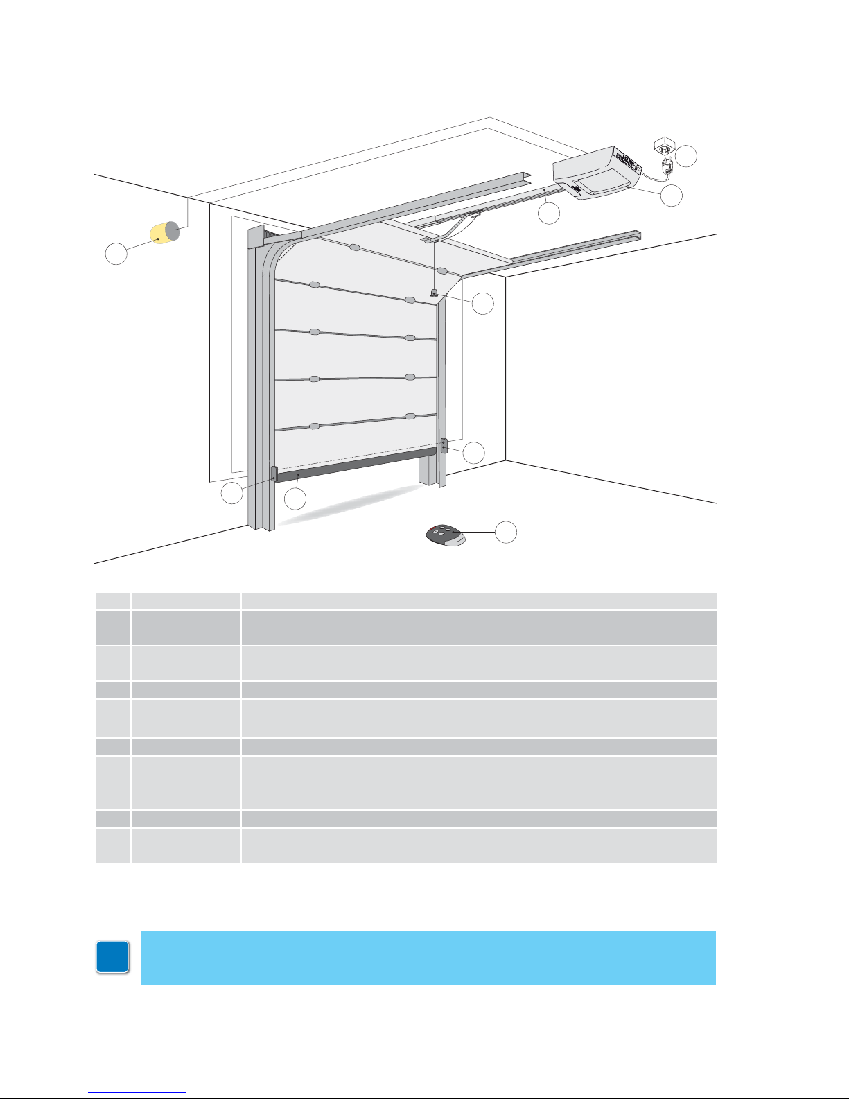
5. Standard installation
Ref. Code Description
1
TOP603H
TOP903H
Motor + control panel
2
TOP803T3
TOP803T4
Belt drive system with 3m steel guide
Belt drive system with 4m steel guide
3 LAMP Flashing light 230 V~ (requires the TOP905AC auxiliary card)
4
ASB1
ASB2
Kit for external release with cord and lock
Blocking device with cord (2000mm)
5 GOL4 Remote control
6
XEL2
LAB4
LAB4S
Photocells
7 Safety edge
A
Connect the power supply to a suitable earthed socket, about 10-50cm from the
pulling unit fixing position.
A
7
RG58 + 2x1.5 mm²
6
2
4
3
6
1
5
TOP905CAB2
TOP905CAB3
i
The declared operating and performance features can only be guaranteed with the use
of ENTREMATIC accessories and safety devices.
Unless otherwise specified, all measurements are expressed in mm.
Page 13
63
IP2179EN - 2015-11-24
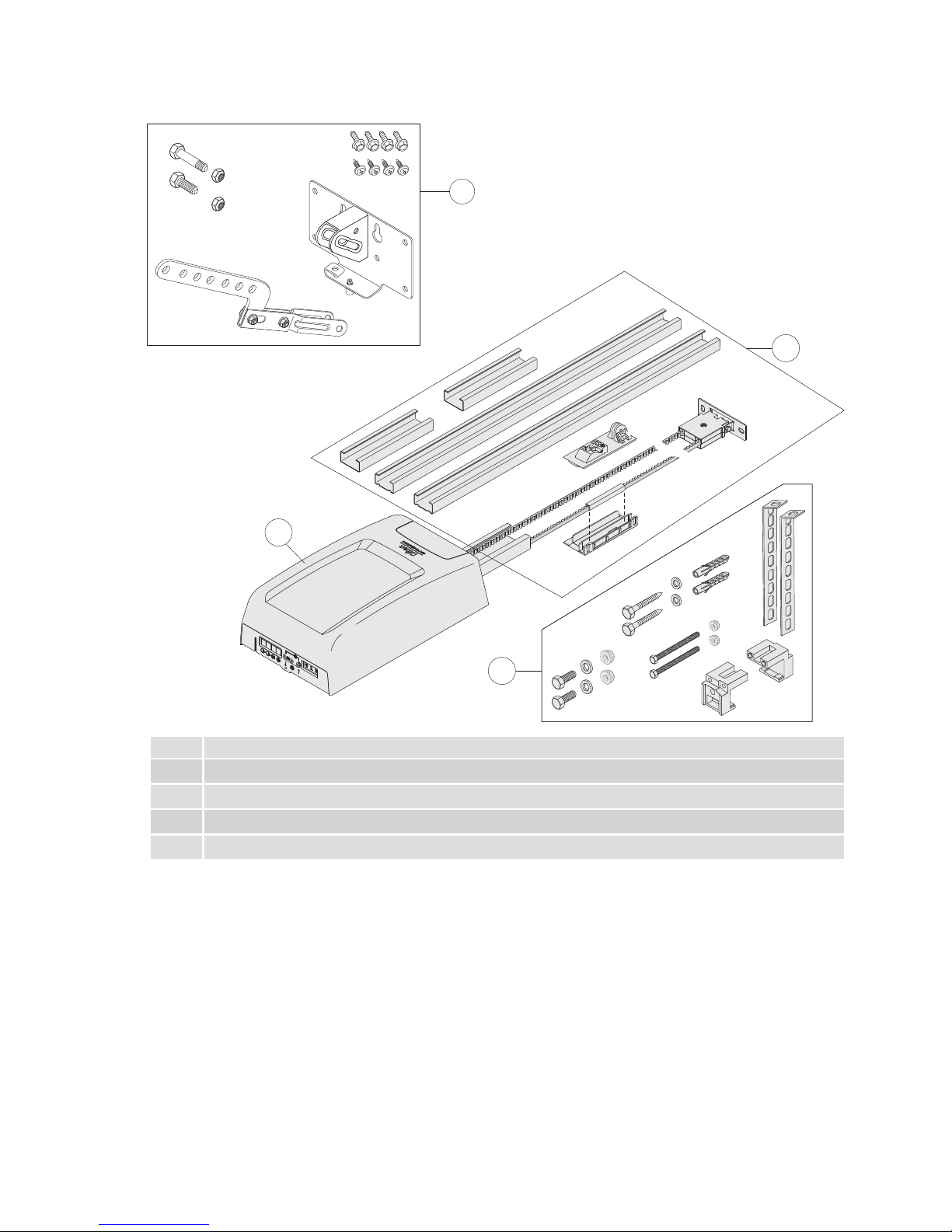
6. Main components
Ref. Description
1 Pulling unit
2 Drive system
3 Ceiling fixing system
4 Traction arm with retention bracket
4
3
2
1
Page 14
64
IP2179EN - 2015-11-24
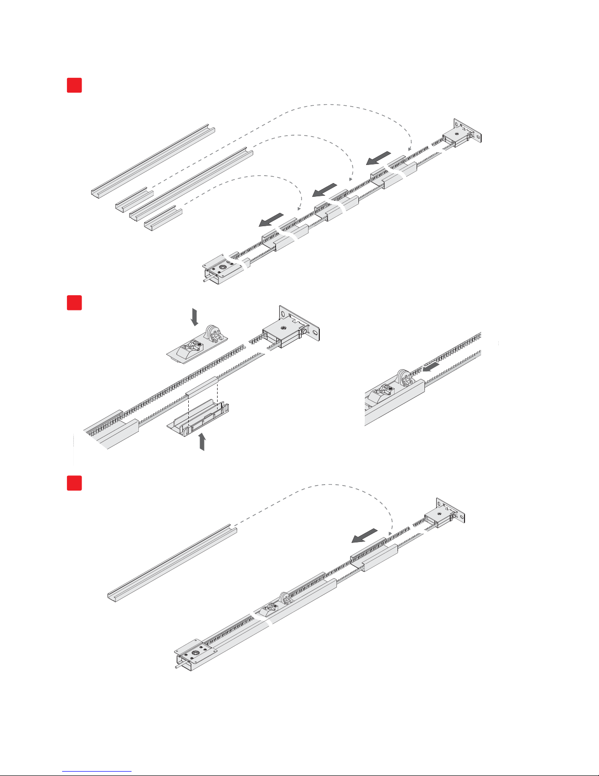
7. Assembly guide
1
2
3
Assemble the drive unit as shown in the figures.
Page 15

65
IP2179EN - 2015-11-24
8. Tensioning the belt
AB
TOP803T3 4-6mm
TOP803T4 6-9mm
BX
X
1.
M8
A
NO
YES
Tighten the locking nut until the belt is correctly tensioned [X] within the guide.
Adjust the dimension [B] according to the type of guide used.
Page 16
66
IP2179EN - 2015-11-24
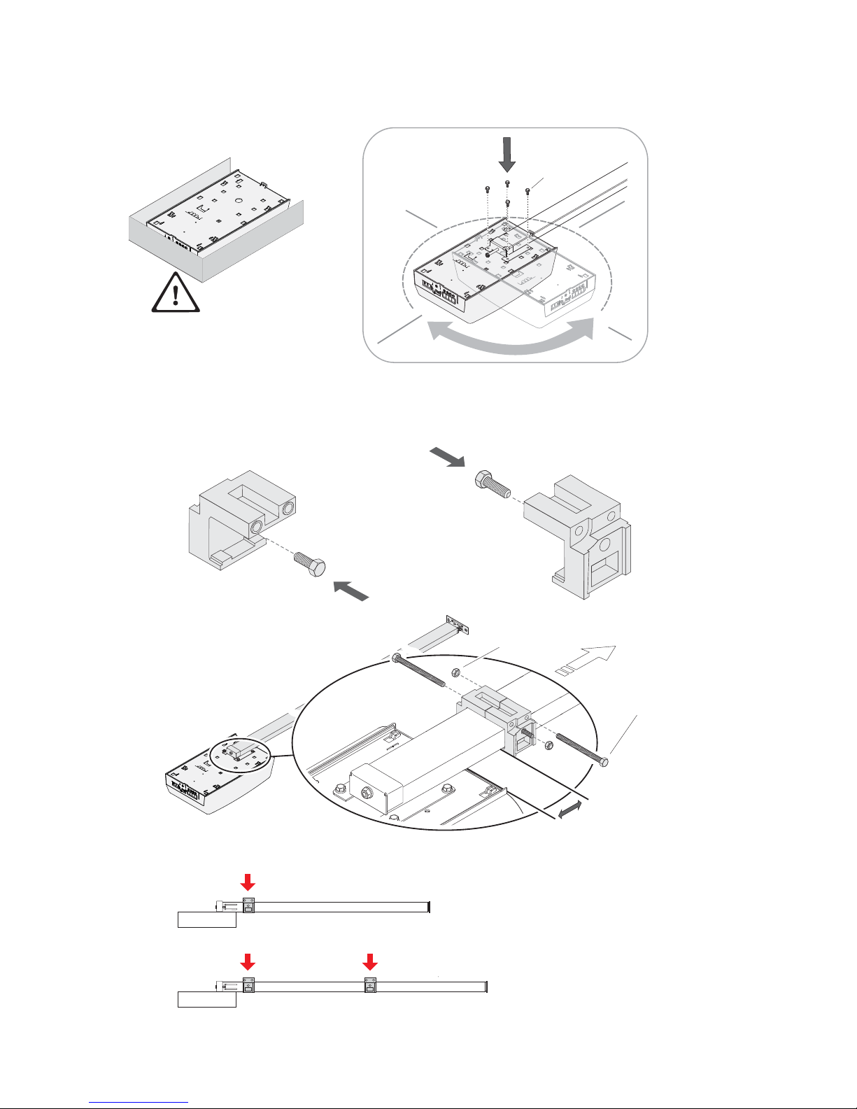
9. Assembling the automation
?
M6x10
M8X25
M8X25
M6x90
0-350 mm
M6
TOP803T3
TOP803T4
x1
x2
Fit the pulling unit to the drive system.
The pulling unit can be rotated by 90°.
Page 17
67
IP2179EN - 2015-11-24
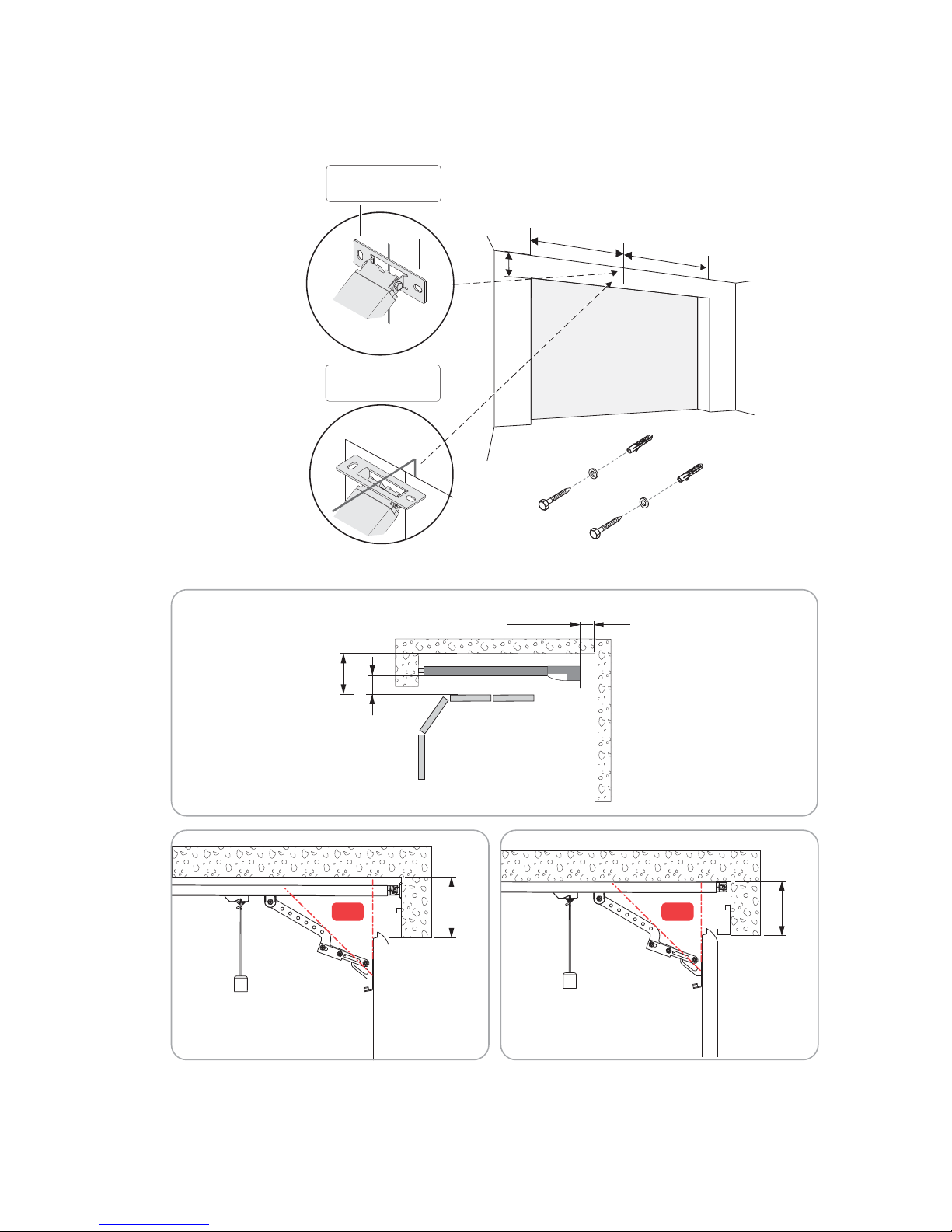
10. Mechanical installation
=
=
A
A = < 150 mm
8x70
8,4x24
≥100 mm
A = > 150 mm
A >150 mm
A <150 mm
5÷15 mm
min. 55 mm
+45°+45°
Select and mark the point where the guide will be mounted on the wall and ceiling.
Page 18
68
IP2179EN - 2015-11-24
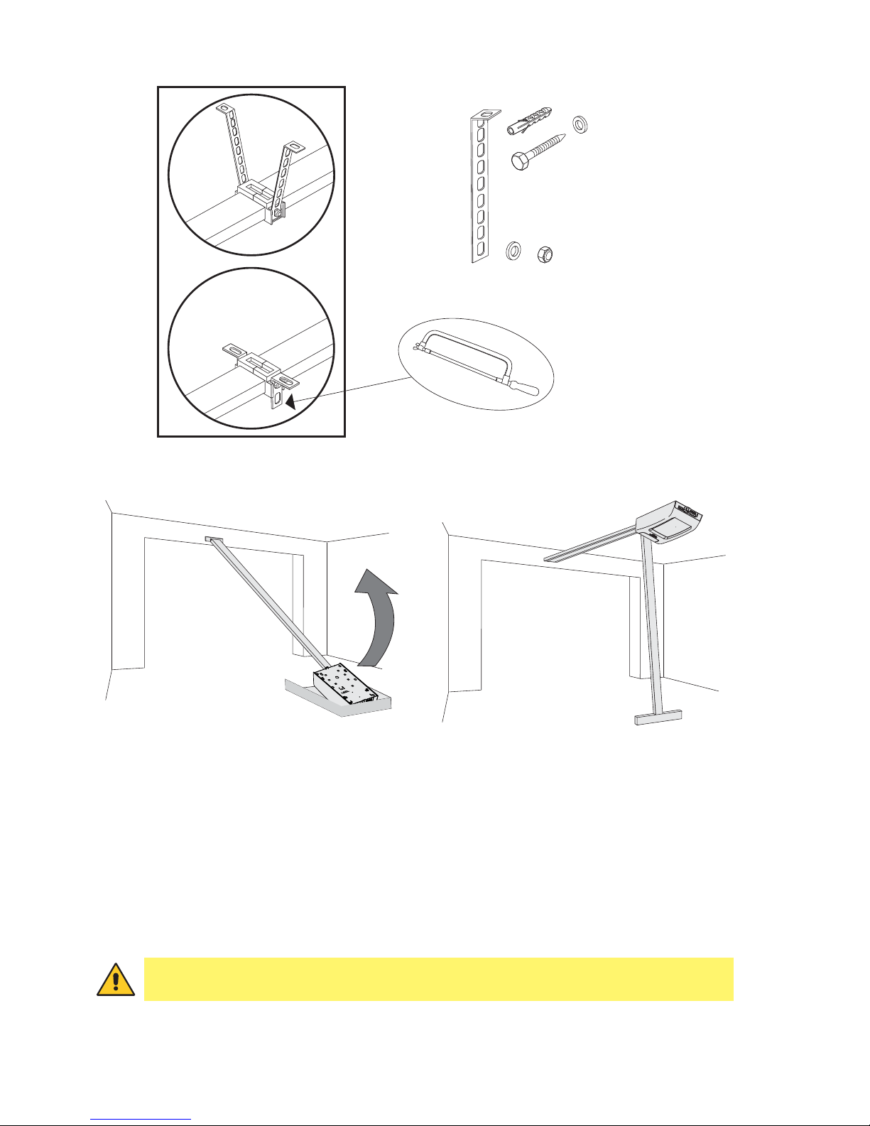
• Check the stability of the door, and make sure it moves smoothly.
• It must be possible to open and close the door easily and smoothly by hand.
• The automation must only be installed in dry places.
• With the pulling unit on the ground, fix the guide to the wall.
• Raise the pulling unit and bend the brackets as necessary (any excess parts can be removed),
then attach to the ceiling.
WARNING: the pulling unit is heavy, so be very careful when raising it.
8x70
8,4x24
max
250 mm
min 10 mm
8,4x24
M8
Page 19
69
IP2179EN - 2015-11-24
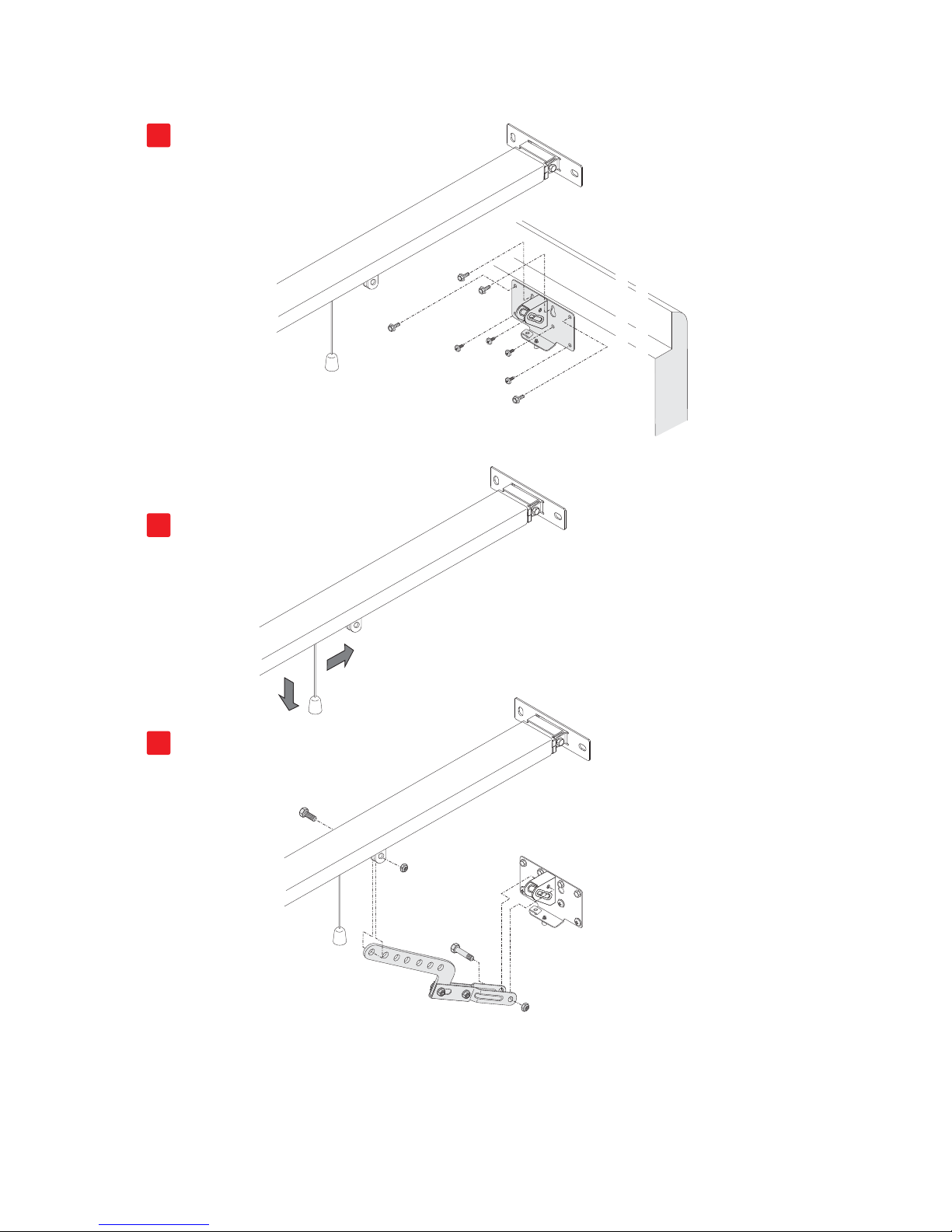
11. Assembling and fastening the arm
Click
1
2
1
2
3
• Fix the retention bracket to the upper part of the door.
• Unlock the automation by pulling the cord downwards until the lock release lever is triggered.
• Bring the carriage near the closed door, and fix the arm as shown in figure 3.
Page 20
70
IP2179EN - 2015-11-24
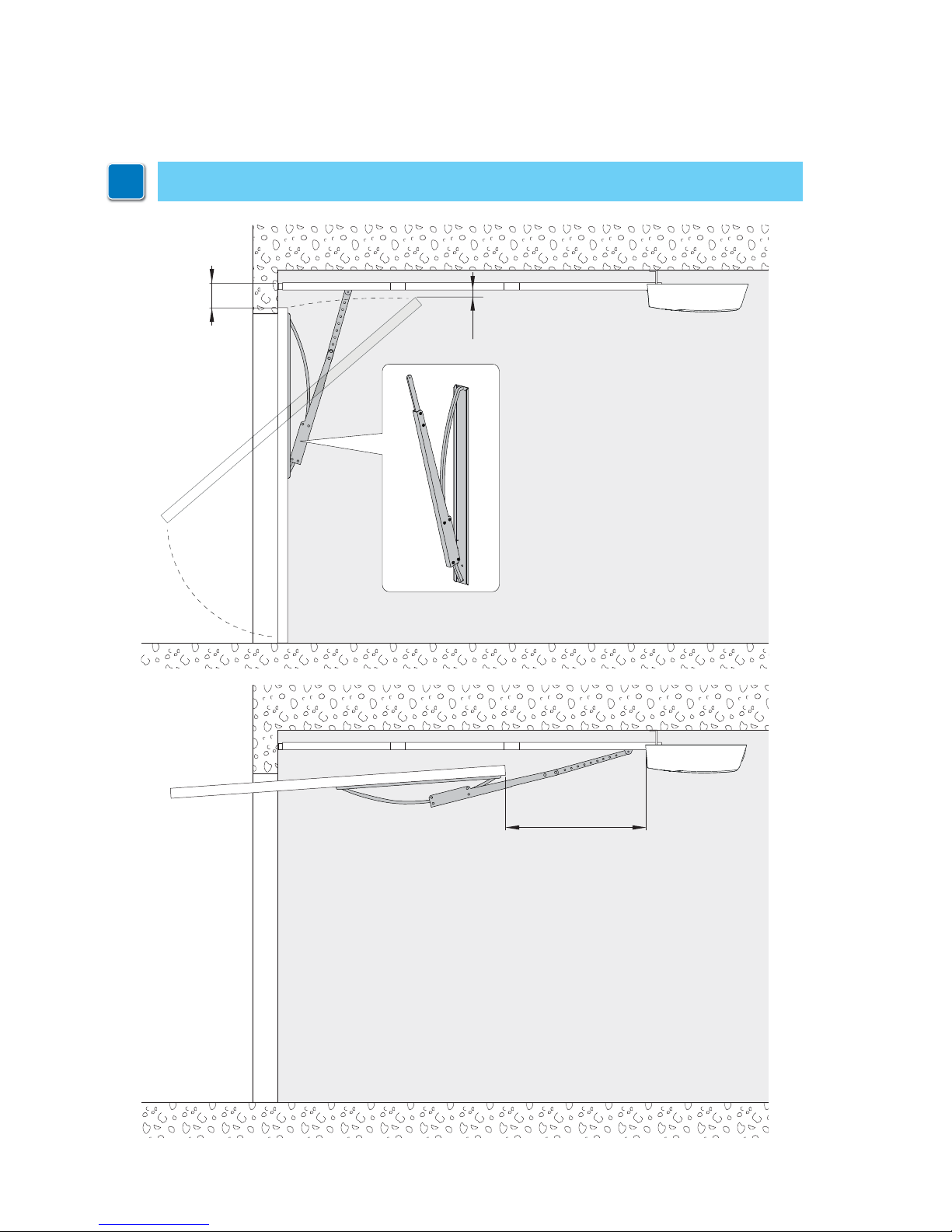
12. Installing the adapter for TOPSB tilting doors
In applications for tilting doors, you must use the TOPSB adapter.
max 210
min 20
min 900
i
For more information, refer to the TOPSB installation manual.
Page 21
71
IP2179EN - 2015-11-24
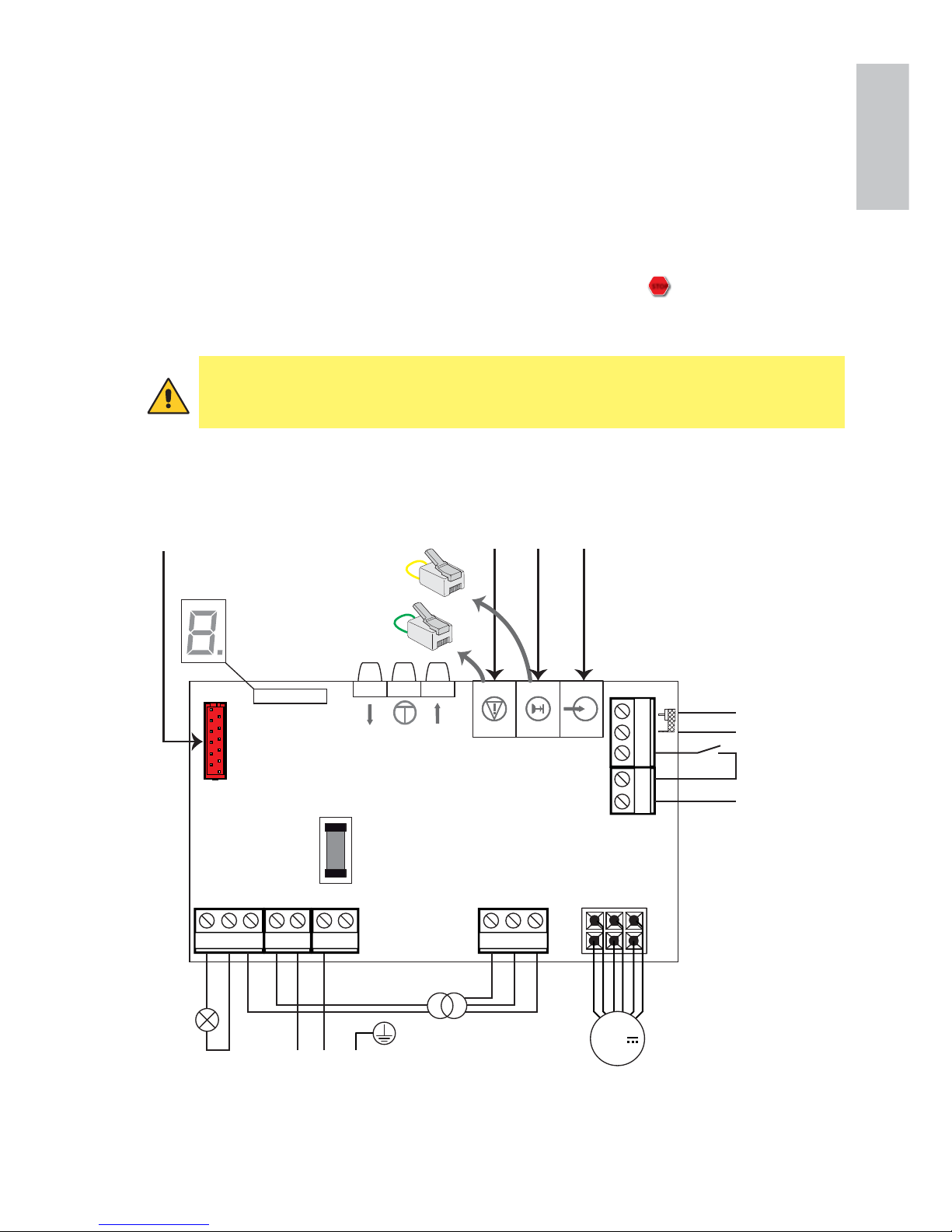
TOP603H
13. Electrical connections TOP603H
123
2019 21
8
24V~ 0V 24V~
91045 6
N
Courtesy
light
DO NOT USE
Step by step
Antenna
SIG
GND
LPE
Power unit
Power supply
Motor
TOP905AC
TOP905CAB1
TOP905CAB2+
TOP905CAB3
F1.6AT line
7
17 18
24V
TOP905CAB2
TOP905CAB4
GREEN
YELL
OW
Installation, electrical connections and adjustments must be performed by qualified personnel, in accordance with Good Working Methods and in compliance with the current regulations.
The automation must be installed in compliance with Standards EN 12453, EN 12445 and EN
12635. The safety devices must be working properly.
Garages without a second entrance must be equipped with an external emergency release device
(to be ordered separately).
If there is a pedestrian door incorporated into the garage door, it must be equipped with a safety
device that prevents it being activated when the garage door is open.
STOP
This safety device must
be connected to the EMERGENCY STOP.
In the external automation section, the connections to the mains power supply and any
other low voltage wires (230V) must be made on an independent channel separated from
the connections to the command and safety devices (SELV = Safety Extra Low Voltage).
Page 22
72
IP2179EN - 2015-11-24
TOP603H
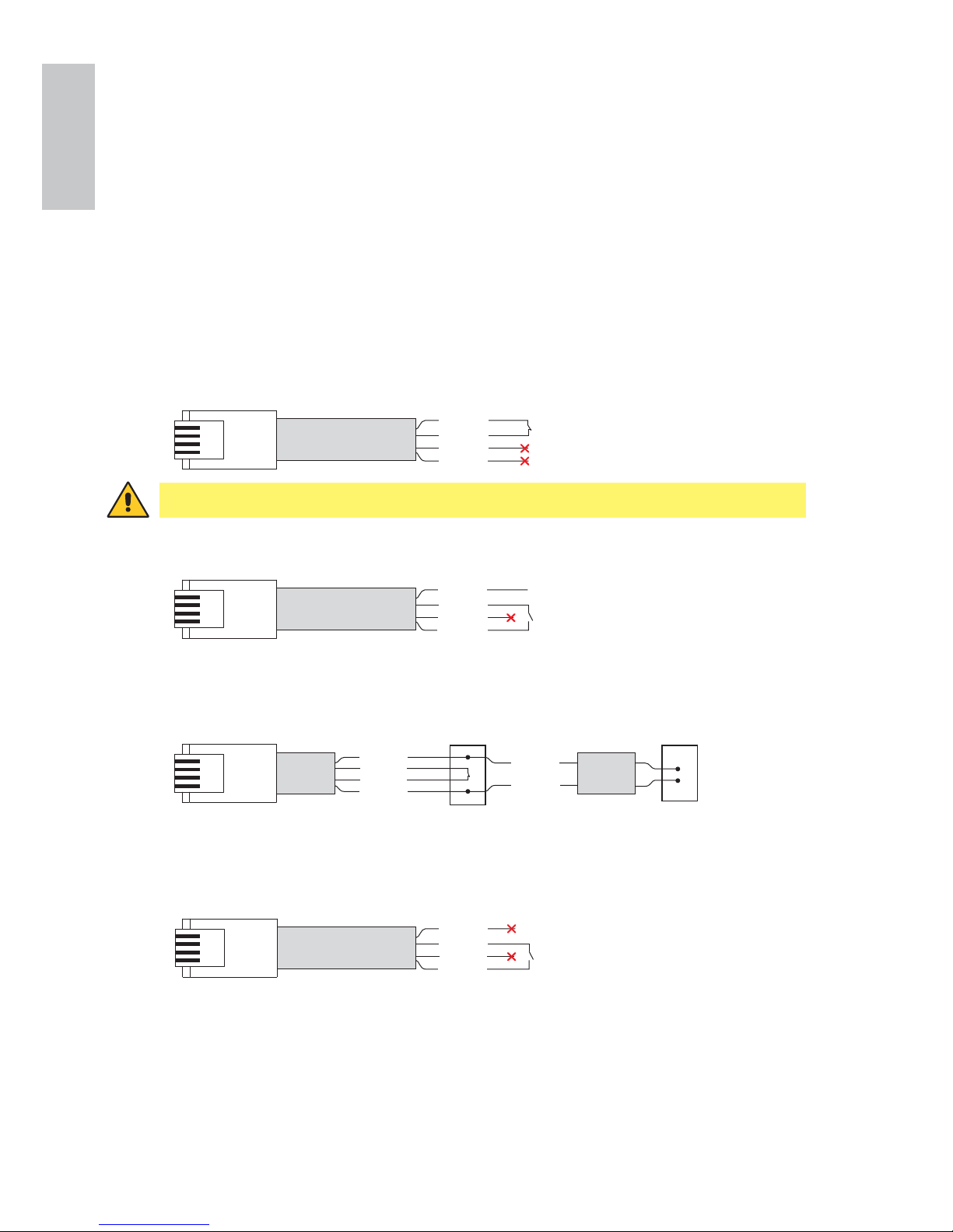
There are two ways to connect the TOP operator to the stop and open commands and the
photocells:
1. By using pre-wired cables (ref. TOP905CAB1, TOP95CAB2, TOP905CAB3, TOP905CAB4),
not included in the operator kit.
2. By using made-to-measure cables.
For pre-wired cables, follow the instructions below:
13.1 Wiring the accessories
13.1.1 Pre-wired cables
Yellow
Red
Green
Black
24V
Yellow
Red
Green
Black
+24V
-0V
Yellow
Black
Yellow
Black
RX
Red
Green
TX
TOP905CAB2 TOP905CAB3
24V
24V
0V
0V
TOP905CAB1 (10 m) - STOP command
TOP905CAB2 (10 m) - OPEN command for powered accessories
TOP905CAB2 (10 m) + TOP905CAB3 (13 m) - Connection of PHOTOCELLS
TOP905CAB4 (10 m) - OPEN contact for NON-powered accessories
Yellow
Red
Green
Black
WARNING: use EXCLUSIVELY for the STOP command.
Page 23
73
IP2179EN - 2015-11-24
TOP603H
13.1.2 Preparation of made-to-measure cables
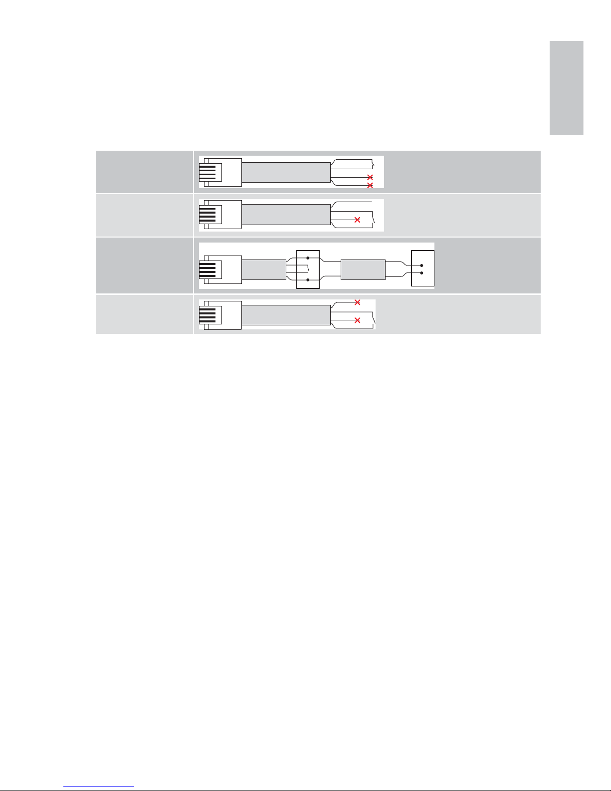
Made-to-measure cables can be made using a cable with the following characteristics: 4-wire
telephone cable AWM20251 VW-1 60°C 150V 4x26AWG (L = 20 m max).
After crimping the RJ11 4P4C connector, the cables must be connected as indicated below:
Stop command
24V
Open command for
powered accessories
24V
0V
Connection of photocells
RX TX
24V
24V
0V
0V
Open contact for nonpowered accessories
Page 24
74
IP2179EN - 2015-11-24
TOP603H
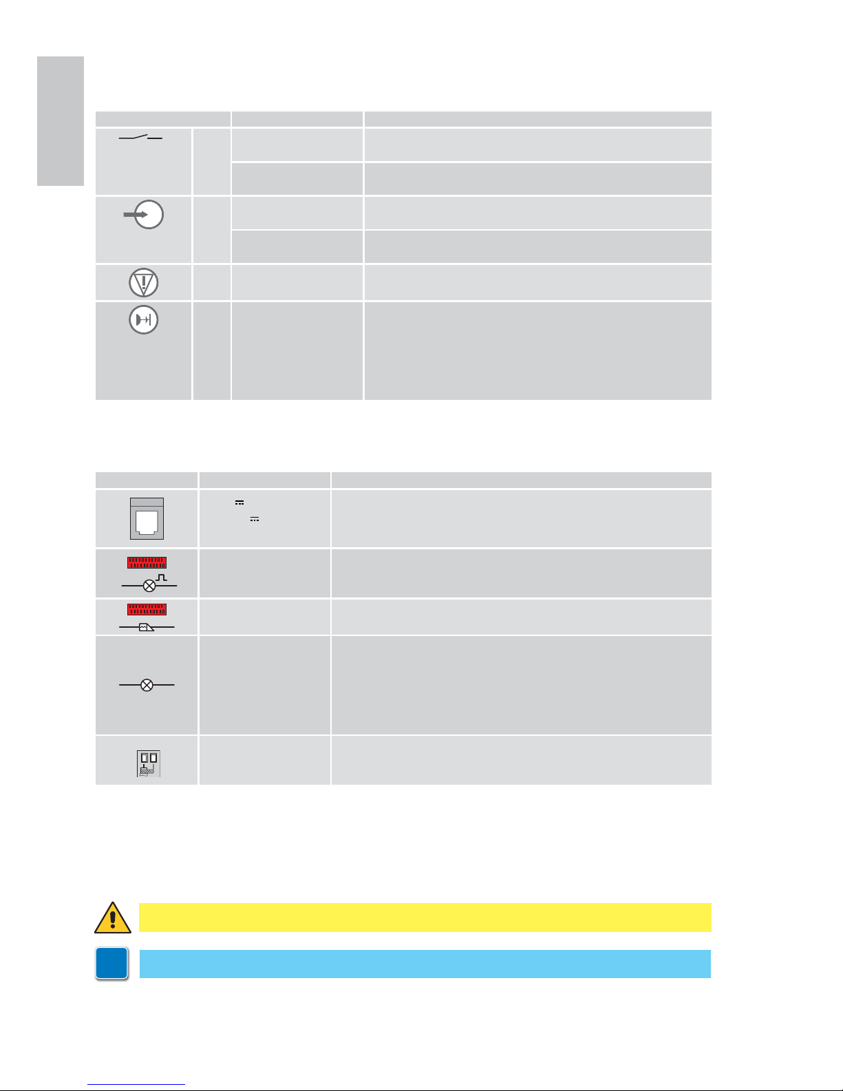
13.2 Commands TOP603H
13.3 Outputs and accessories TOP603H
Command Function Description
18
19 NO STEP-BY-STEP The closure of the contact activates a sequential opening or
closing operation: opening-stop-closing-stop.
OPENING With automatic closure enabled (parameter b4), the closure of
the contact activates an opening operation.
NO STEP-BY-STEP The closure of the contact activates a sequential opening or
closing operation: opening-stop-closing-stop.
OPENING With automatic closure enabled (parameter b4), the closure of
the contact activates an opening operation.
NC STOP The opening of the safety contact causes the current move-
ment to stop, and the automatic closure is disabled.
NC REVERSAL
SAFETY
The opening of the safety contact triggers a reversal of the
movement (reopening) during the closing operation, and the
flashing of the courtesy light.
After the 3rd consecutive reversed movement, the automatic
closure is disabled (if active) and the courtesy light flashes
for about 10 min.
Output Value - Accessories Description
24 V / 0.3A for 2s
24 V
/ 0.08A
continuous
Power supply to accessories.
The maximum continuous absorption refers to all the accessories
installed. Yellow wire (+24V) and black wire (-0V) with TOP905CAB2.
LAMP
230 V~ / 25W
Flashing light (with TOP905AC).
Activated during opening and closing operations.
max 1.6A
Electric lock (with TOP905AC).
Activated for 1s at each start (even with the door open).
1 2
max 230 V~ / 60W
Courtesy light.
Activated for 120s at the end of every operation.
An additional E14 courtesy light can be connected (in parallel) - max
60W or equivalent.
DO NOT CONNECT fluorescent tubular lamps.
NB: some energy-saving lamps may interfere with the radio signal.
20
21
GOL148REA
Antenna
Connect the supplied antenna wire (345mm), or alternatively the
GOL148REA antenna, using an RG58 coaxial cable.
WARNING: make a jumper for all unused NC contacts.
i
Keep the YELLOW and/or GREEN connectors if accessories are to be connected.
Page 25
75
IP2179EN - 2015-11-24
TOP603H
14. Commands and indications
14.1 Deleting the memorised stroke values
14.2 Restoring the factory settings
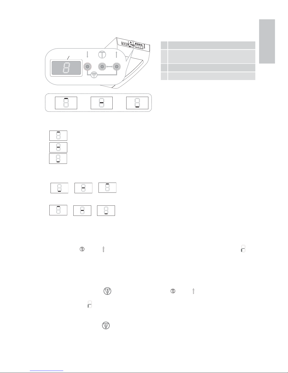
5 Button for door closure / decreased value
6 Menu button / confirm (stroke
memorisation)
7 Button for door opening / increased value
8 Display
567
res.
8
ABC
Status messages
A
door fully OPEN
B
door between the two end stop positions
C
door fully CLOSED
While the door is OPENING, the display visualises:
C
B
A
.
While the door is CLOSING, the display visualises:
A
B
C
.
If you press the [6] and [7] keys simultaneously for a few seconds, the display flashes , the
stroke values are deleted, and the display visualises L ... 4.
NB: the remote controls are not deleted.
Remove the plug from the
connector, then press the [6] and [7] keys simultaneously for
12s.
The display flashes , first slowly and then more quickly.
All the adjustments previously made are deleted, and the factory values are restored.
The stroke values are deleted.
Reconnect the plug to the connector.
The display visualises L ... 4.
NB: the remote controls are not deleted.
The procedures and adjustments can only
be carried out when the display is in mode
A, B or C.
Page 26
76
IP2179EN - 2015-11-24
TOP603H
15. Self-learning of the stroke TOP603H
WARNING: when an automation stroke self-learning operation is carried out, the obstacle detection device is not active.
NB: the self-learning operation can only be carried out during the initial installation or following
an automation RESET. Do not press any keys during this procedure.
1. Turn on the power supply.
• The display flashes L ... 4.
• Press and hold the
[7] button. The door will open.
• The display flashes L ... 4.
• Release the button when the required opening position is reached.
• Use the [7] and [5] buttons to correct the position if necessary.
• The courtesy light flashes 4 times during the operation L ... 4.
2. Press the [6] button. The display flashes L ... 3.
• The automation memorises the opening position and begins a closing operation.
• The courtesy light flashes 3 times.
• When the door reaches the closed position, the display flashes L ... 2. The courtesy light
flashes twice.
• The automation opens automatically as far as the open position. The display flashes
• L ... 1. The courtesy light flashes once.
• The automation automatically recloses as far as the closed position, the display visualises
C
and the door re-opens. The lamp does not flash.
3. The self-learning procedure is complete when the door is open and the courtesy light is ON.
NB: in certain cases, especially when the door moves very smoothly or the traction unit is not
connected to the door, the automatic stroke self-learning procedure may fail. This brings the
procedure back to the initial display condition L ... 4.
In this situation, you must modify parameter b3 = 0 (see ch. 17-18) to guarantee the correct
memorisation of the stroke.
Self-learning of the stroke with a remote transmitter
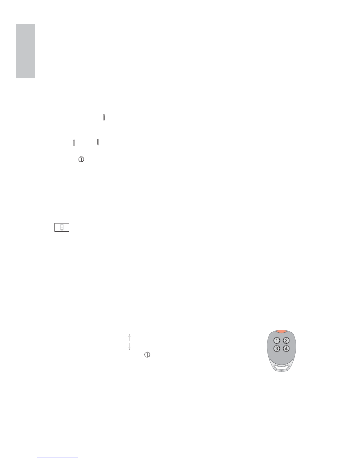
When the automation is delivered or reset, the remote transmitter assumes the following functions:
• (1) has the same function as (UP arrow)
• (3) has the same function as (DOWN arrow)
• (2) or (4) has the same function as (confirm/memorisation)
For the self-learning of the stroke, refer to the procedure explained above.
Once the self-learning phase is complete, key [1] is used to command the door. The other keys can
be used to command other similar automations or other radio receivers.
1 2
3 4
Page 27
77
IP2179EN - 2015-11-24
TOP603H
16. Memorising / Deleting remote controls
16.1 Memorising remote controls via the control panel
16.2 Memorising remote controls from a distance
16.3 Deleting remote controls
1. Press the [7] and [5] keys simultaneously for about 1 s. The display flashes .
2. Press the required key on the remote control.
• The display indicates
for about 1 s, and the remote control is memorised.
• The function of the memorised key is OPEN-STOP-CLOSE-STOP.
NB: with automatic closure enabled (parameter b4), the function of the remote control is OPENING.
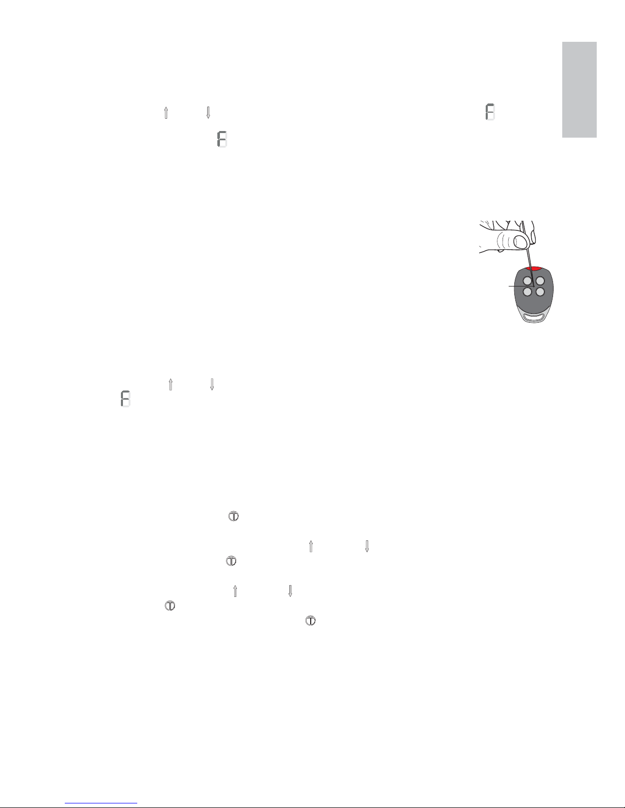
1. Press the PRG of a previously memorised GOL4 transmitter for 5 seconds
(within the range of the receiver) until the LED lights up.
2. Press any one of the CH keys of the new transmitter.
• The new transmitter can memorise the same keys as the existing transmitter.
NB: be careful not to accidentally memorise your neighbours' transmitters.
1. Press the [7] and [5] buttons simultaneously for more than 6 seconds. The display flashes
, first slowly and then more quickly.
• All the remote controls are deleted.
PRG
17. Adjusting the parameters
1. Press the menu button [6] for more than 1.5 s. The display goes to the adjustments menu
or to the last parameter adjusted. The 2-character menu name flashes. For example A ... 0.
2. Select the required parameter using the [7] and/or [5] buttons.
3. Press the menu button [6] for less than 1.5 s. The display indicates the value of the selected
parameter. For example, 0.
4. Alter the value using the [7] and/or [5] buttons. The new value is automatically memorised.
5. Press the [6] button for less than 1.5 s. The display returns to the selected parameter.
• To quit the adjustment mode, press the [6] button for more than 1.5 s.
• The adjustment mode is automatically quit after 15 s of inactivity.
NB: while the adjustment mode is active, the automation cannot accept any commands.
WARNING: if the programming menu values from A0 to A4 are modified, the display visualises
L .. 4 and you must repeat the learning procedure (see chapter 15).
Page 28
78
IP2179EN - 2015-11-24
TOP603H
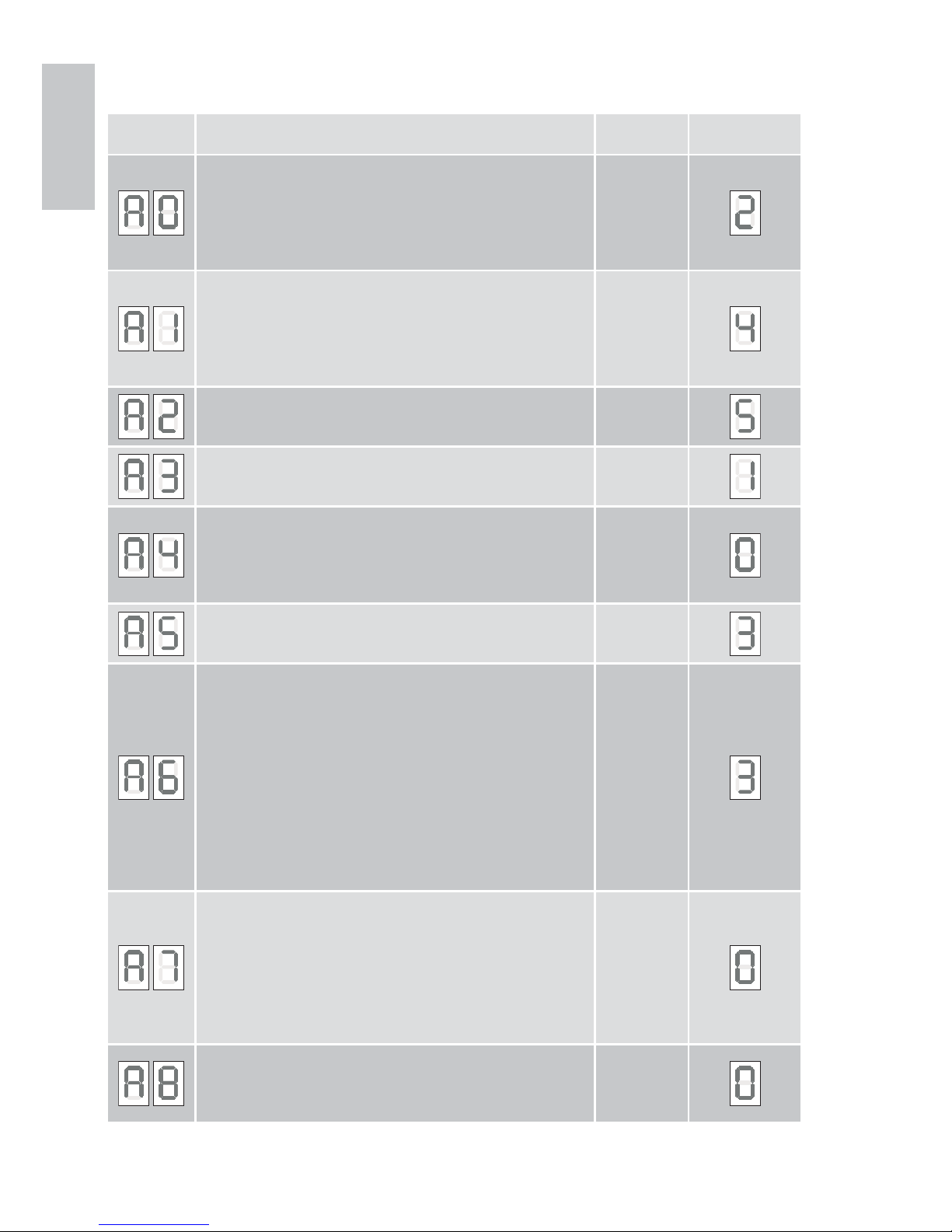
Menu Function, setting range, unit Value
Factory
settings
Deceleration distance on opening
0 = 0cm
1 = 7cm
2 = 14cm
...
9 = 63cm
0 - 9
Deceleration distance on closing
0 = 0cm
1 = 7cm
2 = 14cm
...
9 = 63cm
0 - 9
Deceleration speed on closing (mm/s)
0 = 50mm/s
9 = 140mm/s
0 - 9
Disengagement on the closing stop
0 = disabled
1 = enabled
0 - 1
Direction selection
0 = disabled
1 = enabled
This setting is only possible if the EMERGENCY STOP
connector (1, green) is disconnected.
0 - 1
Thrust adjustment on obstacles during opening
0 - minimum thrust
9 - maximum thrust
0 - 9
Thrust adjustment on obstacles during closing
0 - minimum thrust
9 - maximum thrust
NB: after detecting an obstacle during a closing operation, the
door reverses its stroke for about 800mm. Automatic closure
is disabled (if active) and the courtesy light flashes for about
10 min.
WARNING: to ensure the closing thrust force values return
within the limits established by Standard EN12453, you must
set a value of 1 for parameter A6. This operation must be
carried out by qualified personnel.
0 - 9
Door type:
0 = sectional door
1 = side sectional door with disengagement on obstacle
during opening too
2 = side sectional door / tilting door with soft start
If A7 has been modified, perform a reset then repeat the
learning operation (chapter 15).
0 - 2
Early switch-on of courtesy light for opening and closing (sec.)
0 = disabled
1 = min 2 sec
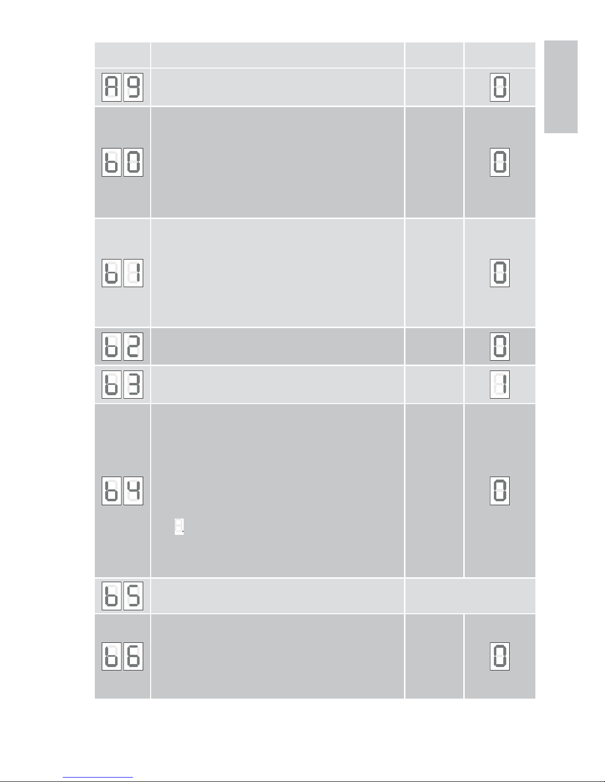
8 = max 16 sec
0 - 8
18. Parameters TOP603H
Page 29
79
IP2179EN - 2015-11-24
TOP603H
Menu Function, setting range, unit Value
Factory
settings
Auxiliary card
0= without TOP905AC
1= with TOP905AC
0 - 1
Relay 1 (with auxiliary card TOP905AC) if A9 = 1
0= no function
1= electric lock (activated for 1 s at each start)
2= flashing light (activated when the motor is moving)
3= photocell test (transmitter voltage interrupted)
4= door OPEN (activated with door fully open)
5= door CLOSED (activated with door fully closed)
6= green light (activated with door fully open)
7= red light (deactivated with door fully open)
0 - 7
Relay 2 (with auxiliary card TOP905AC) if A9 = 1
0= no function
1= electric lock (activated for 1 s at each start)
2= flashing light (activated when the motor is moving)
3= photocell test (transmitter voltage interrupted)
4= door OPEN (activated with door fully open)
5= door CLOSED (activated with door fully closed)
6= green light (activated with door fully open)
7= red light (deactivated with door fully open)
0 - 7
Closing edge protection (with auxiliary card TOP905AC)
0= disabled
1= optic edge FUTURE USE
0 - 1
Detection of stroke with little weight / friction
0= door with little weight / low friction
1= door with standard weight / normal friction
0 - 1
Selection of automatic closure
0= disabled
1= 10 sec
2= 30 sec
3= 1 min ... 5 = 3 min
6= 5 min ... 8 = 15 min
With automatic closure enabled, the OPEN/STOP/CLOSE/STOP
command becomes a simple OPENING command.
The enabling of automatic closure is visualised on the display
with
(point) flashing with the door open, or fixed after a
step-by-step STOP command.
The step-by-step STOP commands given when automatic
closure is enabled are not permanent.
0 - 8
DO NOT USE
Maintenance alarm
0 = disabled
1..9 (1000 door operations)
Example: 5 = 5000 door operations
When the maintenance interval has expired, the courtesy light
flashes after every movement.
A new maintenance alarm setting will reset the counter.
0 - 9
Page 30
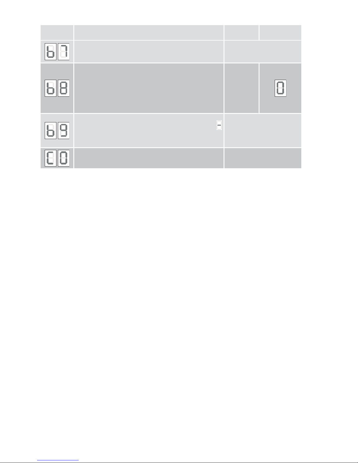
80
IP2179EN - 2015-11-24
Menu Function, setting range, unit Value
Factory
settings
Number of the control panel version:
8 digits are visualised twice in succession, preceded by “-“.
Example: -04200510 indicates: Version: 04, Date: 20.05.10
Help mode
0= control panel free (menu items adjustable)
1= control panel locked (menu items not adjustable)
2= data output (auxiliary card) - FUTURE USE
This setting is only possible if the EMERGENCY STOP
connector (1, green) and the photocell connector (2, yellow)
are disconnected.
0 - 2
Operation count
6 digits are visualised twice in succession, preceded by a
(dash).
Example: -008000 indicates: 8,000 strokes
DO NOT USE
Page 31
81
IP2179EN - 2015-11-24
TOP903H
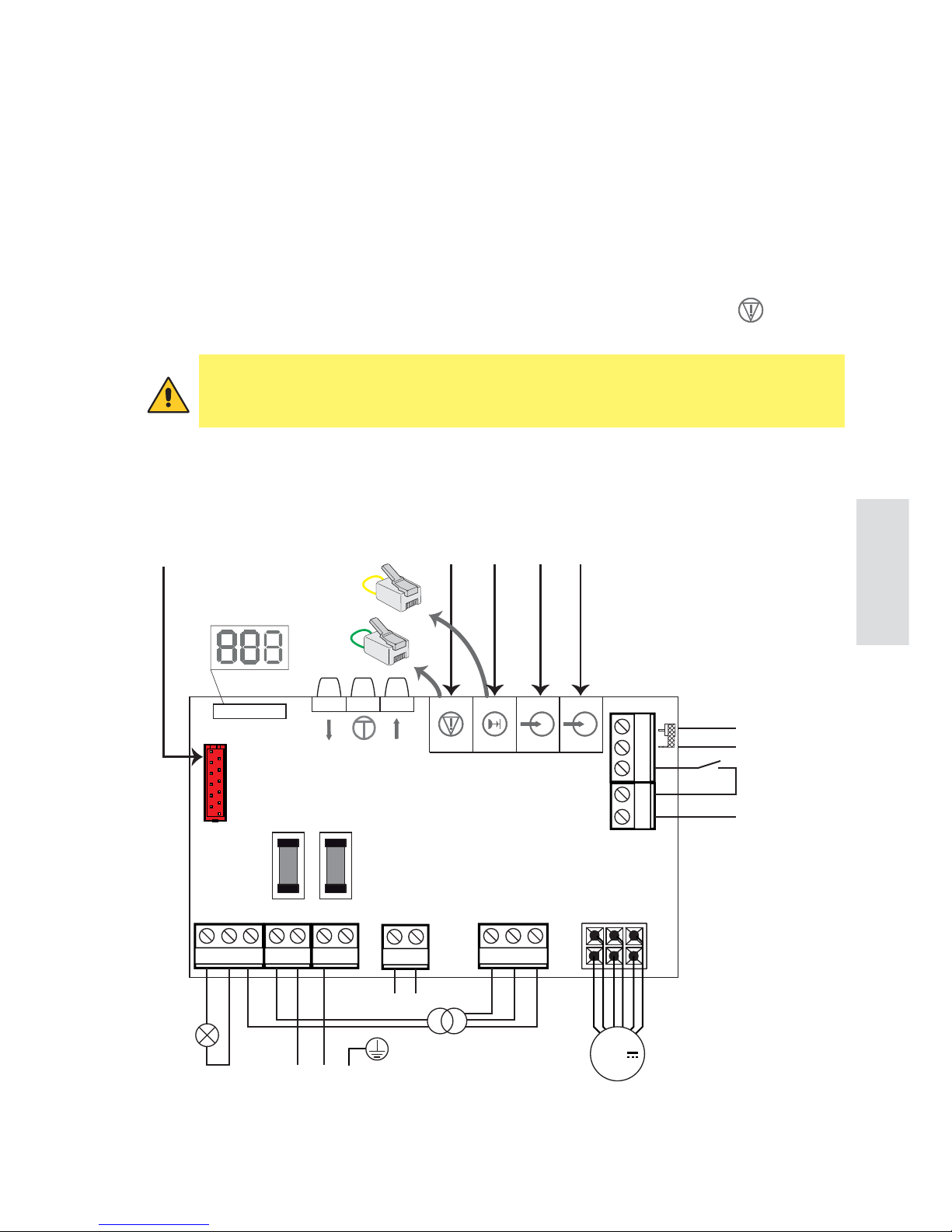
19. Electrical connections TOP903H
Installation, electrical connections and adjustments must be performed by qualified personnel, in accordance with Good Working Methods and in compliance with the current regulations.
The automation must be installed in compliance with Standards EN 12453, EN 12445 and EN
12635.
The safety devices must be working properly.
Garages without a second entrance must be equipped with an external emergency release device
(to be ordered separately).
If there is a pedestrian door incorporated into the garage door, it must be closed and equipped
with a safety device that prevents it being activated when the garage door is open.
This safety
device must be connected to the EMERGENCY STOP input.
123
1615 17
10
24V 0V 24V
11 1245 6
N
Courtesy
light
DO NOT USE
Step by step
Antenna
SIG
GND
L
PE
Power unit
Electriclock
Power supply
Motor
TOP905AC
TOP905CAB1
TOP905CAB2+
TOP905CAB3
F1.6AT electriclock
7
13 14
89
F1.6AT line
24V
TOP905CAB2
TOP905CAB4
GREEN
YELLOW
In the external automation section, the connections to the mains power supply and any
other low voltage wires (230V) must be made on an independent channel separated from
the connections to the command and safety devices (SELV = Safety Extra Low Voltage).
Page 32
82
IP2179EN - 2015-11-24
TOP903H
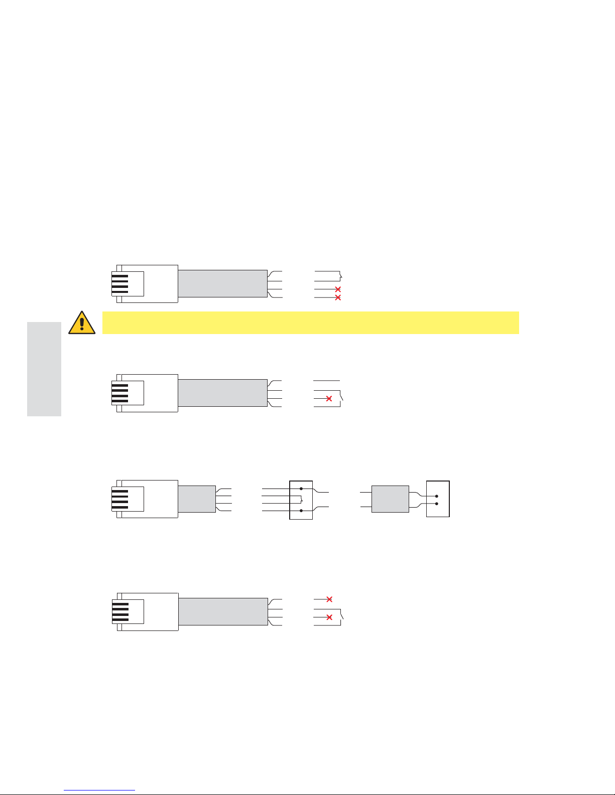
There are two ways to connect the TOP operator to the stop and open commands and the
photocells:
1. By using pre-wired cables (ref. TOP905CAB1, TOP95CAB2, TOP905CAB3, TOP905CAB4),
not included in the operator kit.
2. By using made-to-measure cables.
For pre-wired cables, follow the instructions below:
19.1 Wiring the accessories
19.1.1 Pre-wired cables
Yellow
Red
Green
Black
24V
Yellow
Red
Green
Black
+24V
-0V
Yellow
Black
Yellow
Black
RX
Red
Green
TX
TOP905CAB2 TOP905CAB3
24V
24V
0V
0V
TOP905CAB1 (10 m) - STOP command
TOP905CAB2 (10 m) - OPEN command for powered accessories
TOP905CAB2 (10 m) + TOP905CAB3 (13 m) - Connection of PHOTOCELLS
TOP905CAB4 (10 m) - OPEN contact for NON-powered accessories
Yellow
Red
Green
Black
WARNING: use EXCLUSIVELY for the STOP command.
Page 33
83
IP2179EN - 2015-11-24
TOP903H
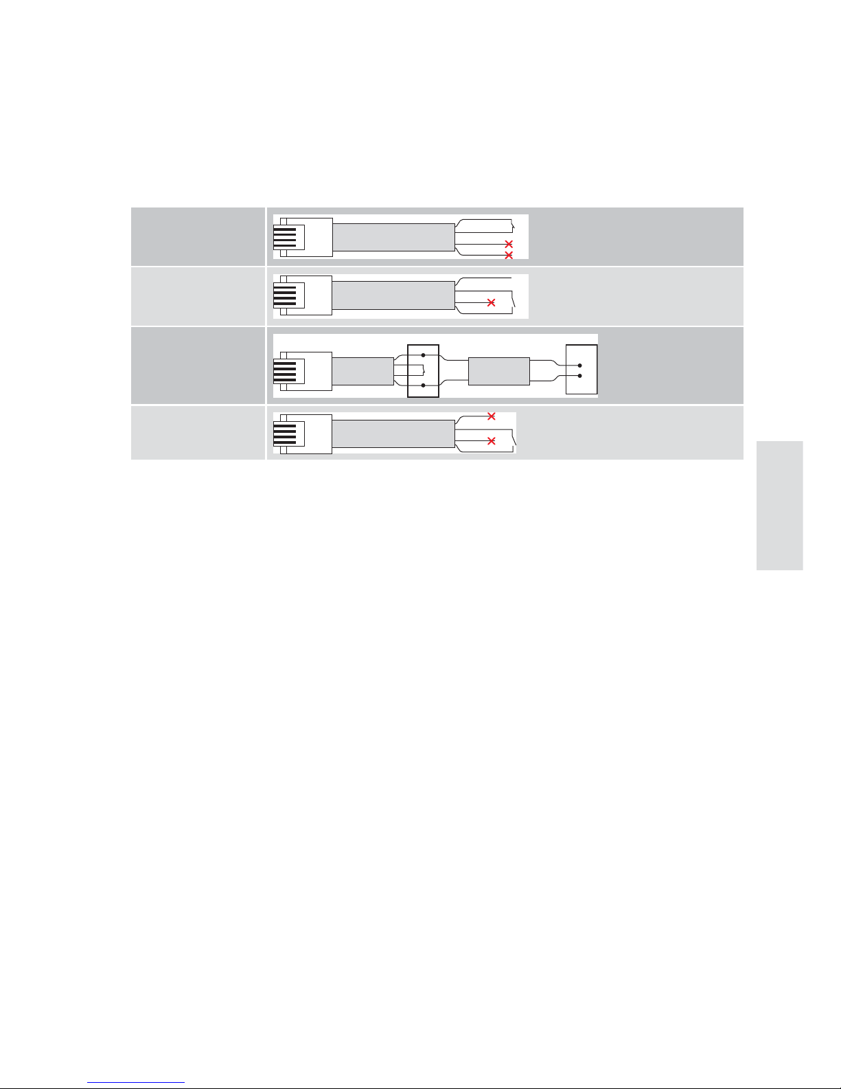
19.1.2 Preparation of made-to-measure cables
Made-to-measure cables can be made using a cable with the following characteristics: 4-wire
telephone cable AWM20251 VW-1 60°C 150V 4x26AWG (L = 20 m max).
After crimping the RJ11 4P4C connector, the cables must be connected as indicated below:
Stop command
24V
Open command for
powered accessories
24V
0V
Connection of photocells
RX TX
24V
24V
0V
0V
Open contact for nonpowered accessories
Page 34
84
IP2179EN - 2015-11-24
TOP903H
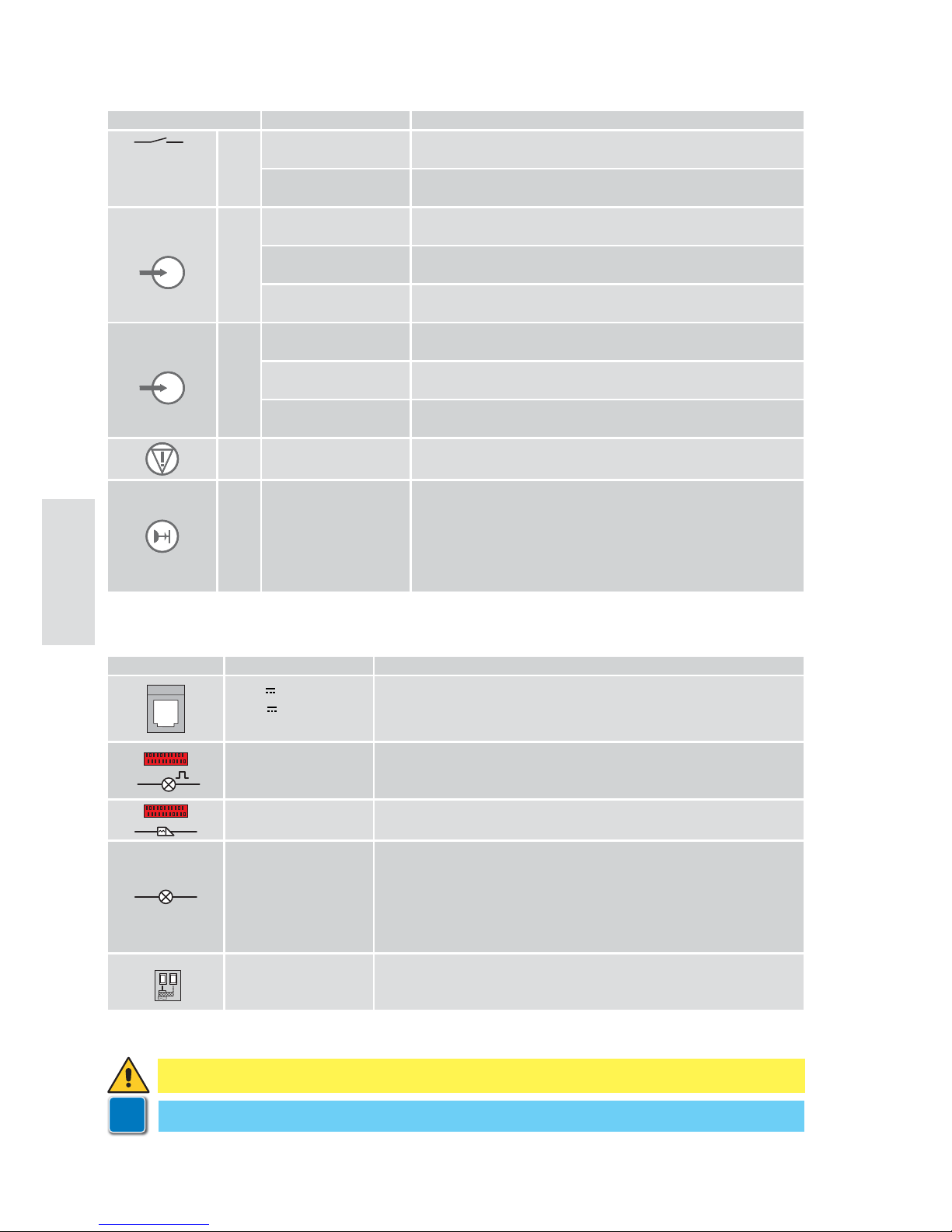
19.2 Commands TOP903H
19.3 Outputs and accessories TOP903H
Command Function Description
14
15 NO STEP-BY-STEP The closure of the contact activates a sequential opening or
closing operation: opening-stop-closing-stop.
OPENING With automatic closure enabled (parameter b4), the closure of
the contact activates an opening operation.
A
NO STEP-BY-STEP The closure of the contact activates a sequential opening or
closing operation: opening-stop-closing-stop.
OPENING With automatic closure enabled (parameter b4), the closure of
the contact activates an opening operation.
ADDITIONAL
FUNCTIONS
See parameter C6.
b
NO STEP-BY-STEP The closure of the contact activates a sequential opening or
closing operation: opening-stop-closing-stop.
OPENING With automatic closure enabled (parameter b4), the closure of
the contact activates an opening operation.
ADDITIONAL
FUNCTIONS
See parameter C6.
NC STOP The opening of the safety contact causes the current movement
to stop, and the automatic closure is disabled (if C5=000).
NC REVERSAL
SAFETY
The opening of the safety contact triggers a reversal of the
movement (reopening) during the closing operation, and the
flashing of the courtesy light.
After the 3rd consecutive reversed movement, the automatic
closure is disabled (if active) and the courtesy light flashes
for about 10 min.
Output Value - Accessories Description
24 V / 0.3A for 2s
24 V
/ 0.08A continuous
Power supply to accessories.
The maximum continuous absorption refers to all the accessories
installed. Yellow wire (+24V) and black wire (-0V) with TOP905CAB2.
LAMP
230 V~ / 25W
Flashing light (with TOP905AC).
Activated during opening and closing operations.
8 9
max 1.6A
Electric lock.
Activated for 1s at each start (even with the door open).
1
2
max 230V~ / 60W
Courtesy light.
Activated for 120s at the end of every operation.
An additional E14 courtesy light can be connected (in parallel) - max
60W or equivalent.
DO NOT CONNECT fluorescent tubular lamps.
NB: some energy-saving lamps may interfere with the radio signal.
16
17
GOL148REA
Antenna
Connect the supplied antenna wire (345mm), or alternatively the
GOL148REA antenna, using an RG58 coaxial cable.
WARNING: make a jumper for all unused NC contacts.
i
Keep the YELLOW and/or GREEN connectors if accessories are to be connected.
Page 35
85
IP2179EN - 2015-11-24
TOP903H
20. Commands and indications
20.1 Deleting the memorised stroke values
20.2 Restoring the factory settings
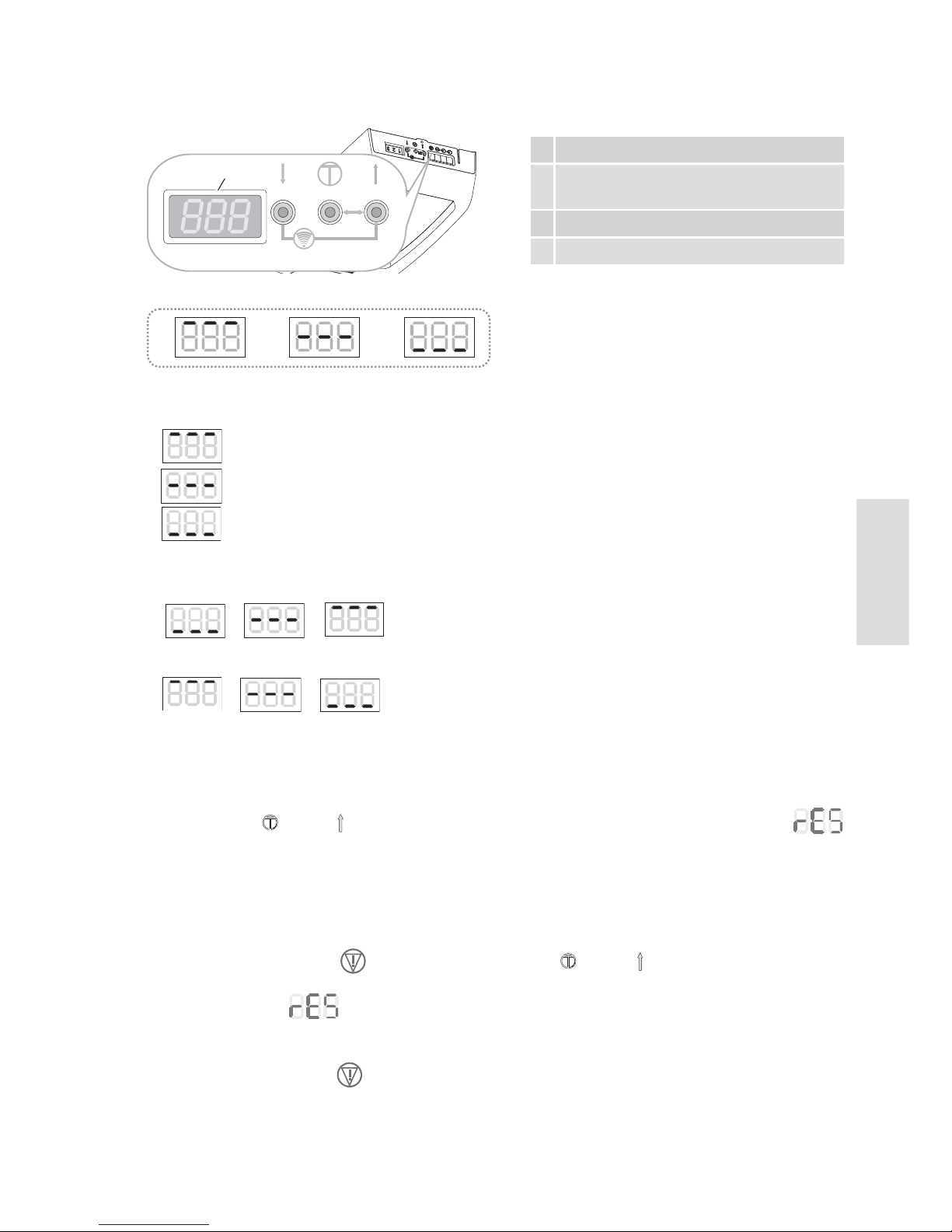
5 Button for door closure / decreased value
6 Menu button / confirm (stroke
memorisation)
7
Button for door opening / increased value
8 Display
Status messages
A
door fully OPEN
B
door between the two end stop positions
C
door fully CLOSED
While the door is OPENING, the display visualises:
C
B
A
.
While the door is CLOSING, the display visualises:
A
B
C
.
If you press the
[6] and [7] keys simultaneously for a few seconds, the display flashes
, the stroke values are deleted, and the display visualises L4.
NB: the remote controls are not deleted.
Remove the plug from the
connector, then press the [6] and [7] keys simultaneously for
12s.
The display flashes , first slowly and then more quickly.
All the adjustments previously made are deleted, and the factory values are restored.
The stroke values are deleted.
Reconnect the plug to the connector.
The display visualises L4.
NB: the remote controls are not deleted.
The procedures and adjustments can only
be carried out when the display is in mode
A, B or C.
ABC
567
res.
8
Page 36
86
IP2179EN - 2015-11-24
TOP903H
21. Self-learning of the stroke TOP903H
WARNING: when an automation stroke self-learning operation is carried out, the obstacle detection device is not active.
NB: the self-learning operation can only be carried out during the initial installation or following
an automation RESET. Do not press any keys during this procedure.
1. Turn on the power supply.
• The display flashes L4.
• Press and hold the
[7] button. The door will open.
• The display flashes L4.
• Release the button when the required opening position is reached.
• Use the [5] button to correct the position if necessary.
• The courtesy light flashes 4 times during operation L4.
2. Press the [6] button. The display flashes L3.
• The automation memorises the opening position and begins a closing operation.
• The courtesy light flashes 3 times.
• When the door reaches the closed position, the display flashes L2. The courtesy light flashes
twice.
• The automation opens automatically as far as the open position. The display flashes L1. The
courtesy light flashes once.
• The automation automatically recloses as far as the closed position, the display visualises
C
and the door re-opens. The lamp does not flash.
3. The self-learning procedure is complete when the door is open and the courtesy light is ON.
NB: in certain cases, especially when the door moves very smoothly or the traction unit is not
connected to the door, the automatic stroke self-learning procedure may fail. This brings the
procedure back to the initial display condition L4.
In this situation, you must modify parameter b3 = 000 (see ch. 23-24) to guarantee the correct
memorisation of the stroke.
Self-learning of the stroke with a remote transmitter
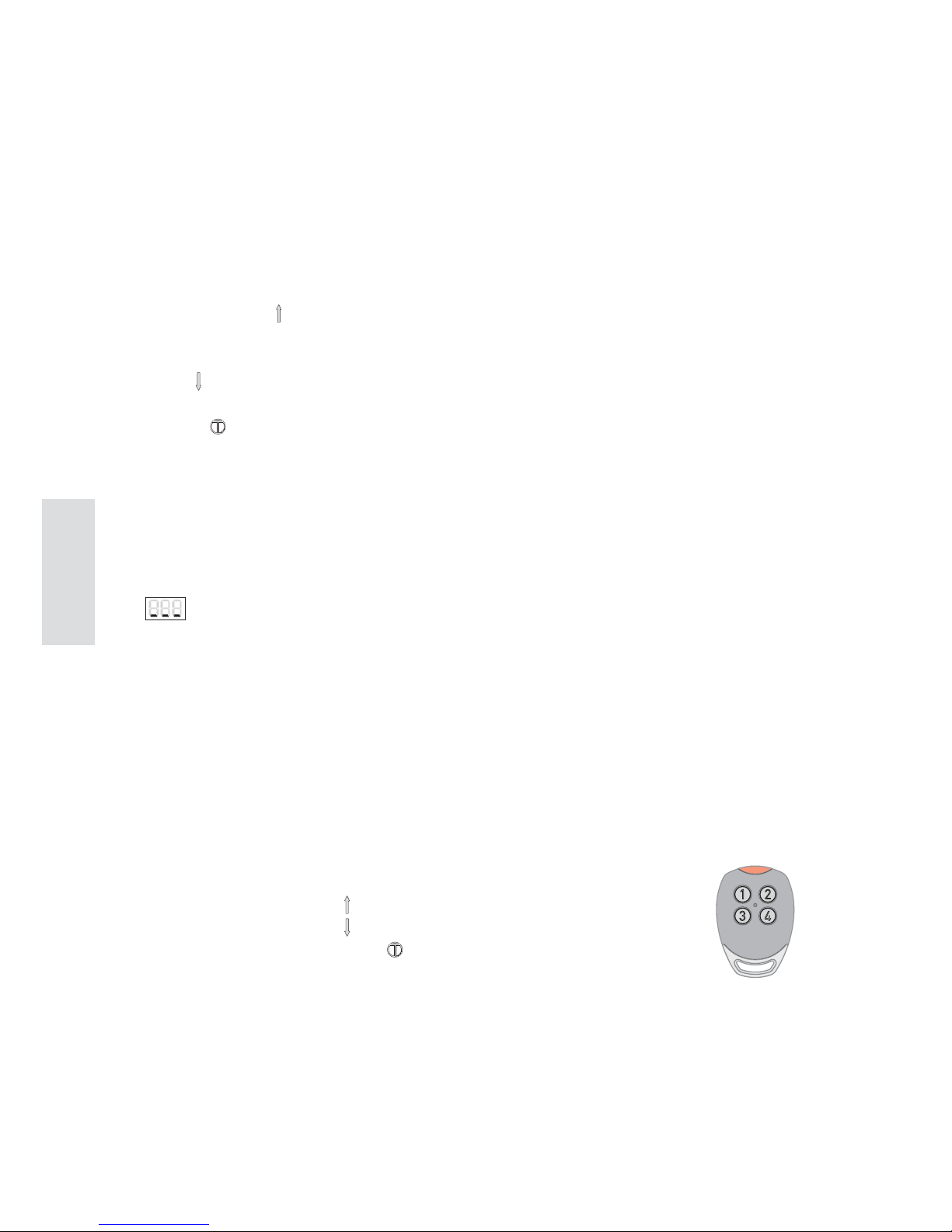
When the automation is delivered or reset, the remote transmitter assumes the following functions:
• (1) has the same function as (UP arrow)
• (3) has the same function as (DOWN arrow)
• (2) or (4) has the same function as (confirm/memorisation)
For the self-learning of the stroke, refer to the procedure explained above.
Once the self-learning phase is complete, key [1] is used to command the door. The other keys can
be used to command other similar automations or other radio receivers.
1 2
3 4
Page 37
87
IP2179EN - 2015-11-24
TOP903H
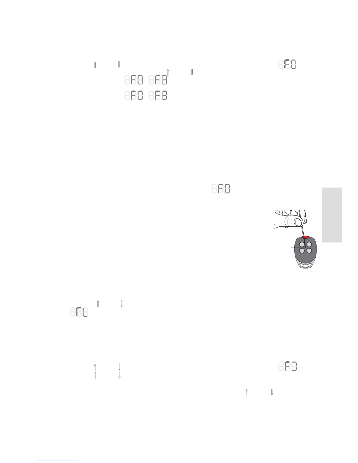
22. Memorising / Deleting remote controls
22.1 Memorising remote controls via the control panel
22.2 Memorising remote controls from a distance
22.3 Deleting remote controls
22.4 Checking the radio reception level
1. Press the [7] and [5] keys simultaneously for about 1 s. The display flashes .
2. Select the required function with the [7] and [5] keys.
• The display indicates
-
• Press the required key on the remote control.
• The display indicates - for about 1 s, and the remote control is memorised.
• The function of the memorised key is:
F0 = OPEN-STOP-CLOSE-STOP
F1 = OPEN-STOP-OPEN-STOP
F2 = CLOSE-STOP-CLOSE-STOP
F3 = STOP
F4 = PARTIAL OPENING
F5 = COURTESY LIGHT ON or RESTART SWITCH-ON TIME
F6 = COURTESY LIGHT ON/OFF
F7 = OPEN
F8 = CLOSE
NB: with automatic closure enabled (parameter b4), the function activates an OPENING
operation and the STOP of the other functions is not permanent.
1. Press the PRG of a previously memorised GOL4 transmitter for 5 seconds
(within the range of the receiver) until the LED lights up.
2. Press any one of the CH keys of the new transmitter.
• The new transmitter can memorise the same keys as the existing transmitter.
NB: be careful not to accidentally memorise your neighbours' transmitters.
1. Press the [7] and [5] buttons simultaneously for more than 6 seconds. The display flashes
, first slowly and then more quickly.
• All the remote controls are deleted.
PRG
The level of radio reception received can be visualised:
• Press the [7] and [5] keys simultaneously for about 1 s. The display flashes .
• Press the [7] and [5] keys simultaneously again for about 1 s to see the radio level.
x = 0 no radio signal ... x = 8 high radio level
The visualisation of the radio level is deactivated when the two keys, [7] and [5], are pressed
again for about 1 s.
Page 38

88
IP2179EN - 2015-11-24
TOP903H
23. Adjusting the parameters
1. Press the menu button [6] for more than 1.5 s. The display goes to the adjustments menu
or to the last parameter adjusted. The 2-character menu name flashes. For example, A0.
2. Select the required parameter using the [7] and/or [5] buttons.
3. Press the menu button [6] for less than 1.5 s. The display indicates the value of the selected
parameter. For example, 000.
4. Alter the value using the
[7] and/or [5] buttons. The new value is automatically memorised.
5. Press the [6] button for less than 1.5 s. The display returns to the selected parameter.
• To quit the adjustment mode, press the [6] button for more than 1.5 s.
• The adjustment mode is automatically quit after 15 s of inactivity.
NB: while the adjustment mode is active, the automation cannot accept any commands.
WARNING: if the programming menu values from A0 to A4 are modified, the display visualises
L4 and you must repeat the learning procedure (see chapter 21).
Page 39
89
IP2179EN - 2015-11-24
TOP903H
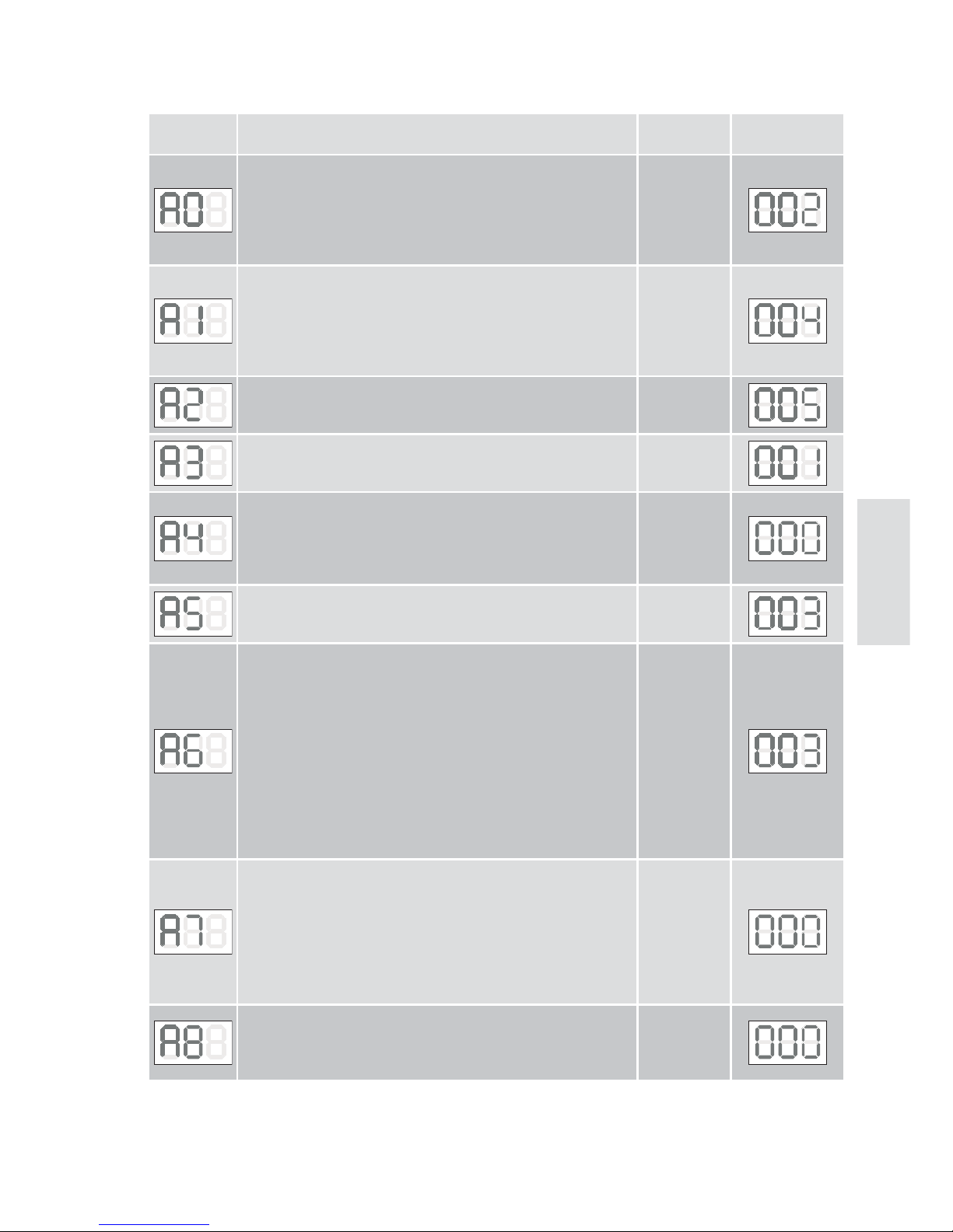
Menu Function, setting range, unit Value
Factory
settings
Deceleration distance on opening
000 = 0cm
001 = 7cm
002 = 14cm
...
009 = 63cm
000 - 009
Deceleration distance on closing
000 = 0cm
001 = 7cm
002 = 14cm
...
009 = 63cm
000 - 009
Deceleration speed on closing (mm/s)
000 = 50mm/s
009 = 140mm/s
000 - 009
Disengagement on the closing stop
000 = disabled
001 = enabled
000 - 001
Direction selection
000 = disabled
001 = enabled
This setting is only possible if the EMERGENCY STOP connector (1, green) is disconnected.
000 - 001
Thrust adjustment on obstacles during opening
000 - minimum thrust
009 - maximum thrust
000 - 009
Thrust adjustment on obstacles during closing
000 - minimum thrust
009 - maximum thrust
NB: after detecting an obstacle during a closing operation, the
automation reverses its stroke for about 800mm. Automatic
closure is disabled (if active) and the courtesy light flashes
for about 10 min.
WARNING: to ensure the closing thrust force values return
within the limits established by Standard EN12453, you must
set a value of 001 for parameter A6. This operation must be
carried out by qualified personnel.
000 - 009
Door type:
000 = sectional door
001 = side sectional door with disengagement on obstacle
during opening too
002 = side sectional door / tilting door with soft start
If A7 has been modified, perform a reset then repeat the
learning operation (chapter 21).
000 - 002
Early switch-on of courtesy light for opening and closing (sec.)
0 = disabled
1 = min 2 sec
8 = max 16 sec
001 - 008
24. Parameters TOP903H
Page 40
90
IP2179EN - 2015-11-24
TOP903H
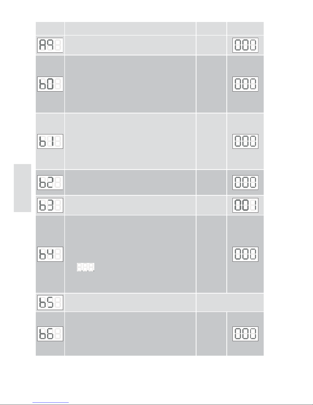
Menu Function, setting range, unit Value
Factory
settings
Auxiliary card
000 = without TOP905AC
001 = with TOP905AC
000 - 001
Relay 1 (with auxiliary card TOP905AC) if A9 = 1
000 = no function
001 = electric lock (activated for 1 s at each start)
002 = flashing light (activated when the motor is moving)
003 = photocell test (transmitter voltage interrupted)
004 = door OPEN (activated with door fully open)
005 = door CLOSED (activated with door fully closed)
006 = green light (activated with door fully open)
007 = red light (deactivated with door fully open)
000 - 007
Relay 2 (with auxiliary card TOP905AC) if A9 = 1
000 = no function
001 = electric lock (activated for 1 s at each start)
002 = flashing light (activated when the motor is moving)
003 = photocell test (transmitter voltage interrupted)
004 = door OPEN (activated with door fully open)
500 = door CLOSED (activated with door fully closed)
006 = green light (activated with door fully open)
007 = red light (deactivated with door fully open)
000 - 007
Closing edge protection (with auxiliary card TOP905AC)
000 = disabled
001 = optic edge FUTURE USE
002 = edge 8k2
000 - 001
Detection of stroke with little weight / friction
000 = door with little weight / low friction
001= door with standard weight / normal friction
000 - 001
Selection of automatic closure
000 = disabled
001 = 5 sec - 010 = 50 sec
011 = 1 min - 040 = 30 min
With automatic closure enabled, the OPEN/STOP/CLOSE/
STOP command becomes a simple OPENING command.
The enabling of automatic closure is visualised on the display
with
(3 points) flashing with the door open, or fixed
after a step-by-step STOP command.
The step-by-step STOP commands given when automatic closure is enabled are not permanent.
000 - 008
DO NOT USE
Maintenance alarm
000 = disabled
001..009 (1,000 door operations)
Example: 005 = 5,000 door operations
When the maintenance interval has expired, the courtesy light
flashes after every movement.
A new maintenance alarm setting will reset the counter.
000 - 009
Page 41
91
IP2179EN - 2015-11-24
TOP903H
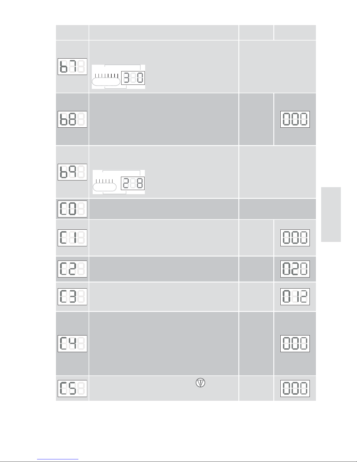
Menu Function, setting range, unit Value
Factory
settings
Number of the control panel version:
The digits from 000 to 007 are visualised in sequence.
Example: version 04 of 20.05.10
04200510
01234567
Help mode
000= control panel free, menu items adjustable
001= control panel locked, menu items not adjustable
002= data output (auxiliary card) - FUTURE USE
This setting is only possible if the EMERGENCY STOP connector (1, green) and the photocell connector (2, yellow) are
disconnected.
000 - 002
Operation count (not adjustable).
The digits from 0 to 5 are visualised in sequence.
Example: 8,000 operations
008000
012345
DO NOT USE
Adjustment of automatic closing time after partial opening.
000 = disabled
001 = 5 secs... 010 = 50 secs
011 = 1 min ... 040 = 30 min
000 - 040
Selection of partial opening distance.
000 = 5 cm
100 = 500 cm
000 - 100
Adjustment of the courtesy light switch-on time.
000 = 0 sec
001 = 10 sec
060 = 600 sec
000 - 060
Adjustment of the automatic closing time after photocell intervention.
000 = disabled
001 = 0.5 s ... 019 = 9.5 s
The count begins with the door fully open, and the closing
operation is performed even with automatic closure (b4 / C1)
disabled.
WARNING: automatic closure is not disabled on the third consecutive direction reversal.
000 - 019
Selection of automatic closure after a STOP
000 = disabled
001 = enabled
000 - 001
Page 42
92
IP2179EN - 2015-11-24
TOP903H
Menu Function, setting range, unit Value
Factory
settings
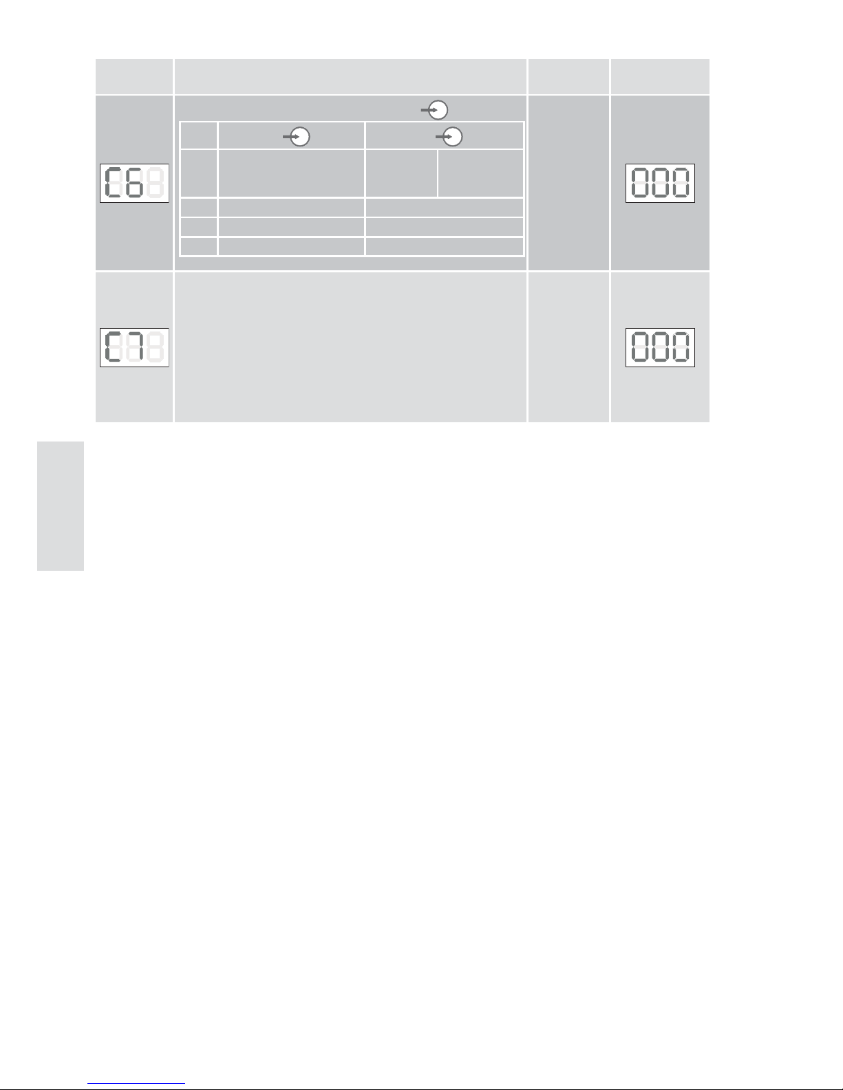
Selection of additional command functions
A b
000 OPEN-STOP-CLOSE-STOP PARTIAL
OPENING
OPEN-STOP
CLOSE-STOP
CLOSE-STOP
001 OPEN-STOP-CLOSE-STOP OPEN-STOP-CLOSE-STOP
002 OPEN-STOP-OPEN-STOP CLOSE-STOP-CLOSE-STOP
003 OPEN CLOSE
000 - 003
Parking assistance (only with photocells installed).
Once the door has opened and the car has passed through,
the courtesy light flashes quickly 3 times when the photocells
are disengaged to indicate that the door can be closed because the car is no longer in the passage opening.
NB: you are advised to install internal photocells.
000 = disabled
001 = enabled
000 - 001
Page 43
93
IP2179EN - 2015-11-24
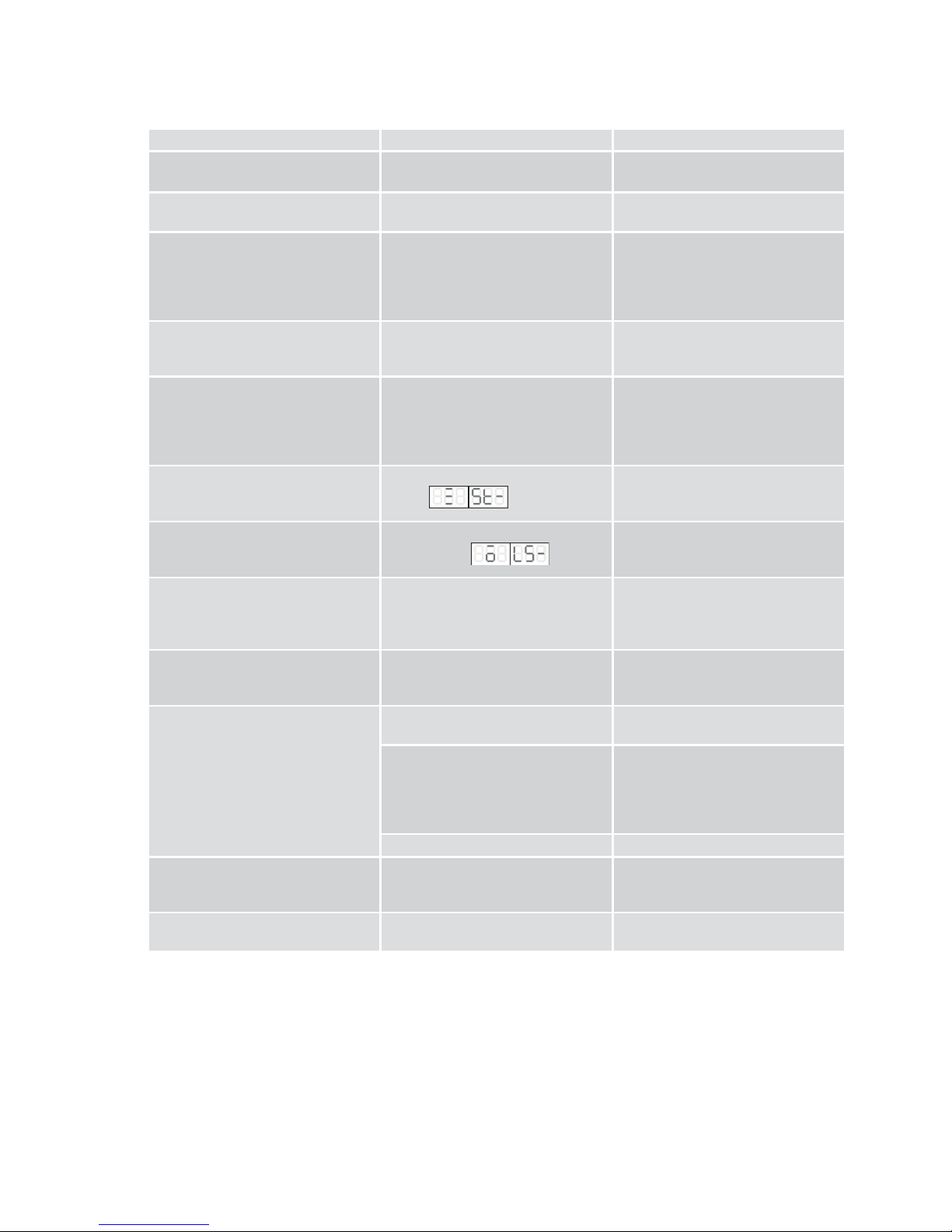
25. Troubleshooting
Problem Possible cause Solution
The courtesy light flashes at regular intervals.
The door has detected an obstacle. Check the door moves smoothly,
and remove any obstacles.
The courtesy light flashes 4 times. The door has not acquired the
stroke.
Perform the learning procedure as
explained in chapter 15 or 21.
The safety devices are not working. Incorrect setting of the door or
safety device.
Perform a reset and repeat the
learning procedure (chapter 15 or
21).
If the problem persists, contact
Technical Service.
The automation doesn't work. No supply voltage, or incorrect
voltage.
Faulty fuse.
Replace the fuse (see chapter 26 Maintenance).
Faulty automation. The carriage release is not cor-
rectly coupled.
The toothed belt is not correctly
tensioned.
The door is blocked.
Check the release, belt or door
movement.
The automation doesn't open. STOP command activated or faulty.
Alarm
Check the STOP command.
If the problem persists, contact
Technical Service.
The automation doesn't close. Safety command activated or
faulty. Alarm
Check the safety devices.
If the problem persists, contact
Technical Service.
The automation closes the door
slowly (soft start) while the courtesy light is flashing.
The automation is performing the
self-learning procedure (see ch. 15
or 21).
Wait until the procedure is completed.
If the problem persists, contact
Technical Service.
The automation stops during its
stroke.
Make sure the door can move
smoothly, and check the safety device is working properly.
Perform a reset and repeat the
learning procedure (chapter 15 or
21).
The remote control doesn't work. Flat batteries. LED not illuminated. Replace the batteries.
If the message of the function assigned to the transmission command is not visualised when the
remote control is enabled.
Memorise the remote control (see
ch. 16 or 22).
Poor reception. Install an optional antenna.
The remote control doesn't always
work.
Radio level too weak.
Radio interference from other
transmission sources.
Check the radio level (see ch. 22 TOP903H only).
The opening command doesn't
work.
Faulty wall-mounting switch. Check the wall-mounting switch
and the connection wire.
Page 44
94
IP2179EN - 2015-11-24
25.1 Alarms
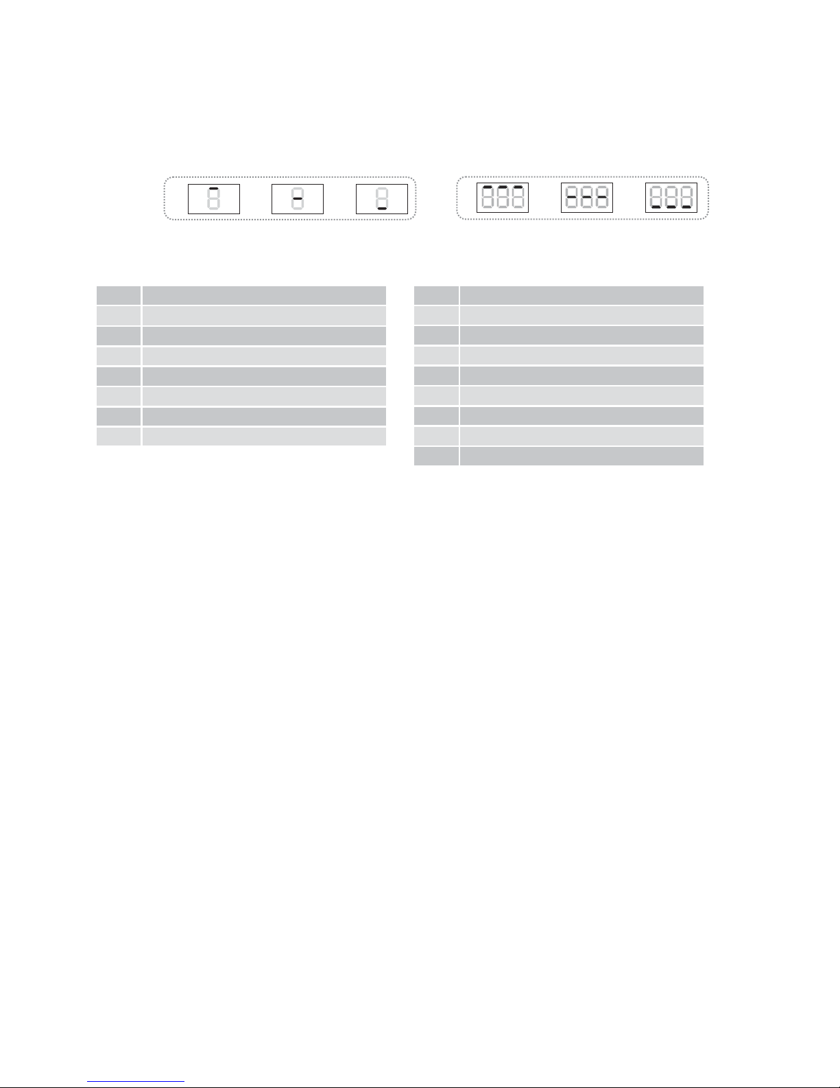
Self-diagnosis
After the learning procedure, after every motor start-up and after every 2.25 hours in the idle
state, the system performs a self-diagnosis test.
No error =
ABC
ABC
002 EEprom data
003 Current measurement
004 Photocell hardware
005 Switch-off thyristors
006 Switch-off relay
007 Watchdog test
008 ROM test
009 RAM test
010 SE test
2 EEprom data
3
Current measurement
4 Photocell hardware
5 Switch-off thyristors
6 Switch-off relay
7 Watchdog test
8 ROM test
9 RAM test
TOP603H error messages TOP903H error messages
If an alarm occurs, perform a RESET (see chapter 14.1 or 20.1).
NB: if the same error occurs in two successive self-diagnosis tests, the control system will be
disabled (commands are rejected).
After about 1 minute, the system performs another self-diagnosis test.
If no errors are detected, the control system is enabled again.
If the error persists, perform a RESET of the factory settings (see chapter 14.2 or 20.2).
All the settings are deleted and the factory values are restored.
Launch a new learning procedure (see chapter 15 or 21) and make the new parameter adjustments (see chapter 18 or 24).
If the problem persists, contact Technical Service.
Page 45
95
IP2179EN - 2015-11-24
26. Maintenance
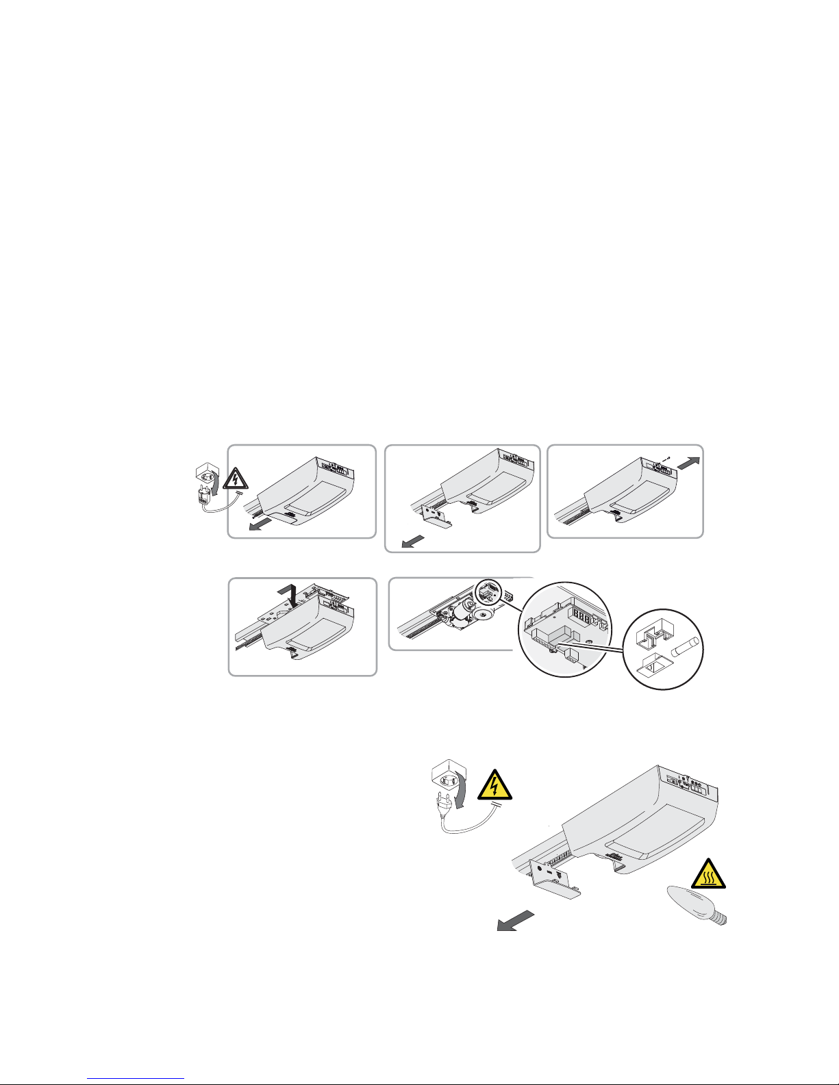
Replacing the fuse
Disconnect the mains plug.
• Remove the cover from the pulling unit.
• Take the faulty fuse S1 (S2) out of the fuse-holder and replace it. Make sure the new fuse is of
the correct value.
• Replace the pulling unit cover.
Restore the mains connection.
Replacing the courtesy light
Disconnect the mains plug.
• Remove the diffuser from the pulling unit.
• Replace the E14-40 W light bulb (max 60W
or equivalent).
WARNING: handle with care since the light bulb
may be very hot.
NB: some energy-saving bulbs may interfere
with the radio signal.
• Replace the diffuser on the pulling unit.
• Restore the mains connection.
1.
2.
3.
4.
5.
S1
S2
Monthly maintenance tasks
• Check the emergency release is working properly.
• Check the safety devices (if installed) are working properly.
• Check the obstacle detection function is working properly.
Six-monthly maintenance tasks
• Check the stability of the automation and make sure the screws and nuts are correctly tightened.
(E14-max. 60W)
Page 46
96
IP2179EN - 2015-11-24
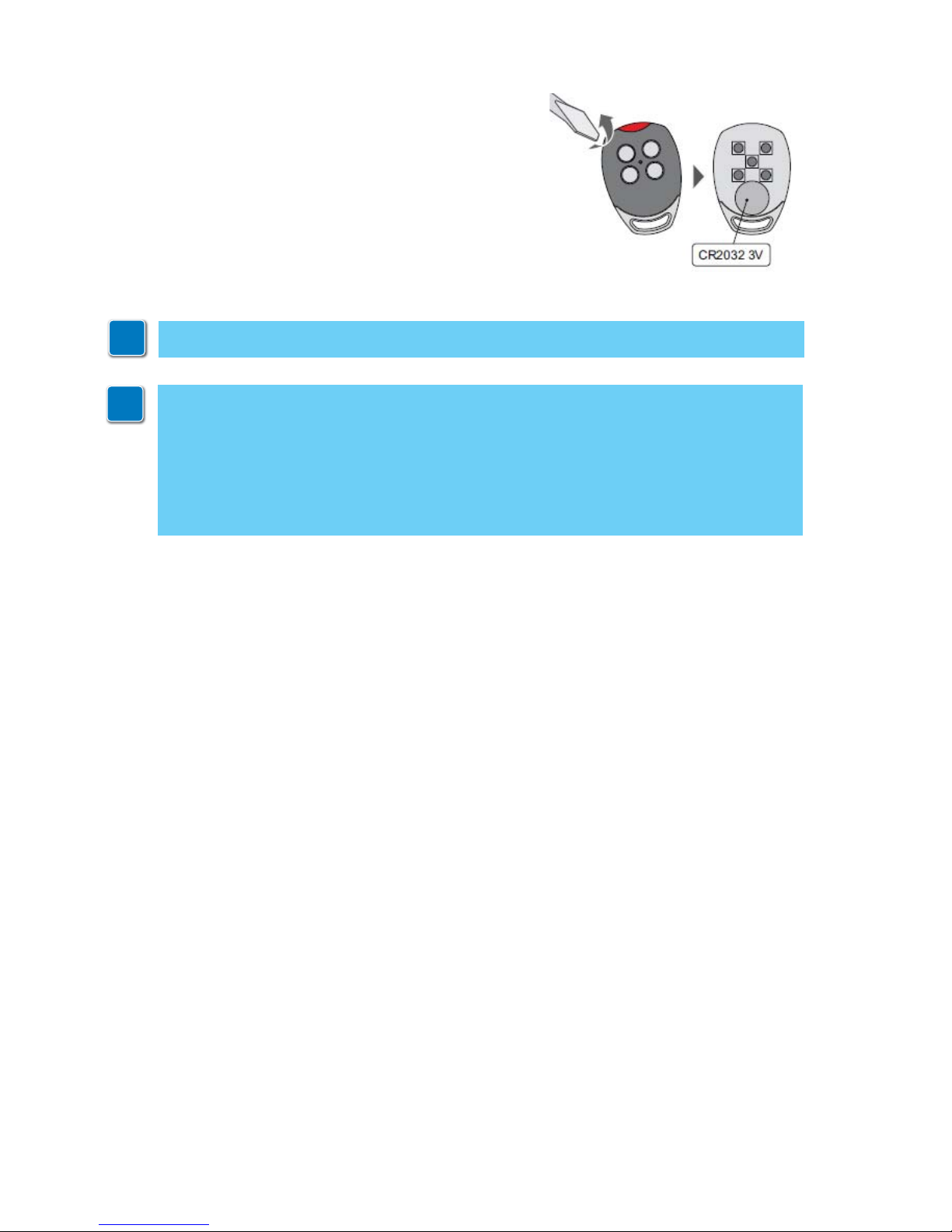
Replacing the remote control battery
Be extremely careful when replacing the battery.
Pay attention to the polarities.
Do not handle the battery with pliers or other tools, to
avoid the risk of discharge or explosion.
To ensure an optimum performance, you are advised to
replace the battery once a year or when you notice a substantial loss of range.
Dispose of used batteries in an environmentally-friendly
way.
i
NB: for spare parts, see the spares price list.
i
Only use original spare parts when repairing or replacing products.
The installer must supply all information concerning the automatic, manual and emergency
operation of the motorised door or gate, and must provide the user with the operating
instructions.
The installer must prepare and keep a maintenance record showing all the routine and
extraordinary maintenance work carried out.
Page 47

97
IP2179EN - 2015-11-24
All the rights concerning this material are the exclusive property of Entrematic Group AB.
Although the contents of this publication have been drawn up with the greatest care, Entrematic Group AB cannot be held responsible in any way for any damage caused by mistakes or omissions. We reserve the right
to make changes without prior notice.
Copying, scanning or changing in any way is expressly forbidden unless authorised in writing by Entrematic
Group AB.
Page 48

Entrematic Group AB
Lodjursgatan 10
SE-261 44, Landskrona
Sweden
www.ditecentrematic.com
IP2179EN - 2015-11-24
 Loading...