

Page 1
Ditec ION4-ION6
Sliding gates
(translation of the original instructions)
www.entrematic.com
IP2288EN • 2019-04-10
Technical Manual
Page 2
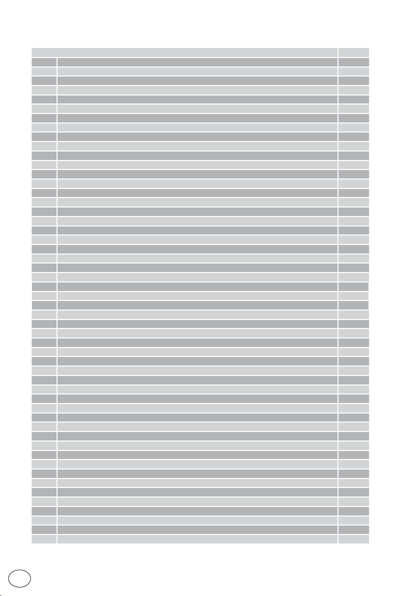
Contents
1. General safety precautions 3
General safety precautions for the user 4
2. Declaration of incorporation of partly completed machinery 5
2.1 Machinery Directive 5
3. Technical specifications 6
4. Standard installation 7
5. Dimensions 8
6. Main components 8
7. Installation 9
7.1 Preliminary checks 9
7.2 Base plate position 9
7.3 Gearmotor installation 10
7.4 Rack installation
7.5 Operation with virtual encoder 12
7.6 Installation of optional accessories 12
7.6.1
Magnetic limit switches
7.6.2
Battery kit
7.6.3
Remote release handle
8. Electrical connections 13
9. LCU48 card 14
10. Using of the menus 15
10.1 Switching the display on and off 15
10.2 Navigation keys 15
10.3 Menu map 16
11. Product start-up 18
11.1 WZ configuration wizard menu 18
12. Commands 20
12.1
SOFA1-SOFA 2 or GOPAVRS self-controlled safety edge
13.
Outputs and accessories
14.
Jumper setting
15.
Adjustments
15.1
Main menu
15.2
Second level menu - AT (Automatic Configurations)
15.3
Second level menu - BC (Basic Configurations)
15.3.1
Additional BC level parameters that can be configured (available with AT → AA enabled)
15.4
Second level menu - BA (Basic Adjustment)
15.4.1
Additional BA level par ameters that can be configured (available with AT → AA enabled)
15.5
Second level menu - RO (Radio Operations)
15.5.1
Additional RO level par ameters that can be configured (available with AT → AA enabled)
15.6
Second level menu - SF (Special Functions)
15.6.1
Additional SF level parameters that can be configured (available with AT → AA enabled)
15.7
Second level menu - CC (Cycle Counter)
15.7.1
Additional CC level parameters that can be configured (available with AT → AA enabled)
15.8
Second level menu - EM (Energy Management)
15.8.1
Additional EM level parameters that can be configured (available with AT → AA enabled)
15.9
Second level menu - AP (Advanced Parameters)
15.9.1
Additional AP level parameters that can be configured (available with AT → AA enabled)
16.
Signals visualised on the display
16.1
Display of automation status
16.2
Display of safety devices and commands
16.3
Display of alarms and faults
17.
Troubleshooting
Subject Page
11
12
12
12
21
21
22
23
23
24
25
26
27
28
30
31
32
33
34
35
35
36
36
38
40
40
42
43
46
IP2288EN
EN
2
Page 3
1. General safety precautions
Please follow these instructions. Failure to observe the information given in
this manual may lead to personal injury or damage to the equipment.
Keep these instructions for future reference.
This installation manual is intended for qualified personnel only.
Installation, electrical connections and adjustments must be performed by qualified personnel, in accordance with Good Working Methods and in compliance with the current regulations.
Read the instructions carefully before installing the product.
Bad installation could be dangerous.
This manual and those for any accessories can be downloaded from www.entrematic.com.
The packaging materials (plastic, polystyrene, etc.) should not be discarded in the environ-
ment or left within reach of children, as they are a potential source of danger.
Before installing the product, make sure it is in perfect condition.
Do not install the product in explosive areas and atmospheres: the presence of inflammable
gas or fumes represents a serious safety hazard.
Before installing the motorisation device, make all the necessary structural modifications to
create safety clearance and to guard or isolate all the crushing, shearing, trapping and general
hazardous areas.
Make sure the existing structure is up to standard in terms of strength and stability. The motorisation device manufacturer is not responsible for failure to observe Good Working Methods
when building the frames to be motorised, or for any deformation during use.
The safety devices (photocells, safety edges, emergency stops, etc.) must be installed taking into
account: applicable laws and directives, Good Working Methods, installation premises, system
operating logic and the forces developed by the motorised door or gate.
The safety devices must protect against crushing, cutting, trapping and general danger areas
of the motorised door or gate.
Display the signs required by law to identify hazardous areas.
Each installation must bear a visible indication of the data identifying the motorised door or gate.
When nece ssar y, connec t the motor ised door or gate to an effective earthing system that complies with the current safety standards.
During installation, maintenance and repair operations, cut off the power supply before
opening the cover to access the electrical parts.
The automation protection casing must be removed by qualified personnel only.
The electronic parts must be handled using earthed antistatic conductive arms. The manu-
facturer of the motorisation declines all responsibility if component parts not compatible
with safe and correct operation are fitted.
Only use original spare parts for repairing or replacing products.
The installer must supply all information concerning the automatic, manual and emergency operation of the motorised door or gate, and must provide the user with the operating instructions.
The installer must ensure that the temperature range indicated in the technical specifications
is compatible with where the gate will be used.
IP2288EN
3
EN
Page 4

General safety precautions for the user
These precautions are an integral and essential part of the product
and must be supplied to the user.
Read them carefully since they contain important information on safe
installation, use and maintenance.
These instructions must be kept and forwarded to all possible future
users of the system.
This product must only be used for the specific purpose for which it
was designed.
Any other use is to be considered improper and therefore dangerous.
The manufacturer cannot be held responsible for any damage caused
by improper, incorrect or unreasonable use.
Avoid operating in the proximity of the hinges or moving mechanical
parts. Do not enter within the operating range of the motorised door
or gate while it is moving.
Do not obstruct the motion of the motorised door or gate, as this may
cause a dangerous situation.
The motorised door or gate may be used by children over the age of 8
and by people with reduced physical, sensorial or mental abilities, or
lack of experience or knowle dge, as long as they are properly super vised
or have been instructed in the safe use of the device and the relative
hazards.
Children must be supervised to make sure they do not play with the
device, nor play/remain in the sphere of action of the motorised door
or gate.
Keep remote controls and/or any other command devices out of the
reach of children, to avoid any accidental activation of the motorised
door or gate.
In the event of a product fault or malfunction, turn off the power supply
switch. Do not attempt to repair or intervene directly, and contact only
qualified personnel.
Failure to comply with the above may cause a dangerous situation.
Any repair or technical intervention must be carried out by qualified
personnel.
Cleaning and maintenance work must not be carried out by children
unless they are supervised.
To ensure that the system works efficiently and correctly, the manufacturer’s indications must be complied with and only qualified personnel
must perform routine maintenance on the motorised door or gate. In
particular, regular checks are recommended in order to verify that the
safety devices are operating correctly.
All installation, maintenance and repair work must be documented and
IP2288EN
EN
4
Page 5

made available to the user.
Only lock and release the door wings when the motor is switched off.
Do not enter within the operating range of the wing.
To dispose of electrical and electronic equipment correctly, users
must take the product to special "recycling centres" provided by
the municipal authorities.
2. Declaration of incorporation of partly completed machinery
(Directive 2006/42/EC, Annex II-B)
The manufacturer Entrematic Group AB, with headquarters in Lodjursgatan 10, SE-261 44 Landskrona, Sweden, declares that the Ditec ION4-ION6 automation for swing gates:
- is designed to be installed on a manual gate to form a machine pursuant to Directive 2006/42/
EC. The manufacturer of the motorised gate must declare conformity with Directive 2006/42/
EC (annex II-A) prior to initial machine start-up;
- complies with the applicable essential safety requirements indicated in Annex I, Chapter 1 of
the Directive 2006/42/EC;
- complies with the RED Directive 2014/53/EU;
- the safety functions are compliant with Category 2, PLc according to EN ISO 13849-1;
- the technical documentation complies with Annex VII-B of the Directive 2006/42/EC;
- the technical documentation is managed by the Technical Office of Entrematic Italy (with
headquarters in Largo U. Boccioni 1 – 21040 Origgio (VA) – ITALY) and is available upon request,
sending an e-mail to [email protected] ;
- a copy of the technical documentation will be given to competent national authorities, following
a suitably justified request.
Landskrona, 26-02-2018 Matteo Fino
(Chairman)
2.1 Machinery Directive
Pursuant to Machinery Directive (2006/42/EC) the installer who motorises a door or gate has the
same obligations as the manufacturer of machinery and as such must:
- prepare the technical data sheet which must contain the documents indicated in Annex V of the
Machinery Directive;
(The technical data sheet must be kept and placed at the disposal of competent national authori-
ties for at least ten years from the date of manufacture of the motorised door or gate);
- draw up the EC Declaration of Conformity in accordance with Annex II-A of the Machinery Direc-
tive and deliver it to the customer;
- affix the EC marking on the motorised door or gate, in accordance with point 1.7.3 of Annex I of
the Machinery Directive;
- ensure compliance of the motorised door or gate with safety regulations, by installing the neces-
sary safety devices;
IP2288EN
5
EN
Page 6
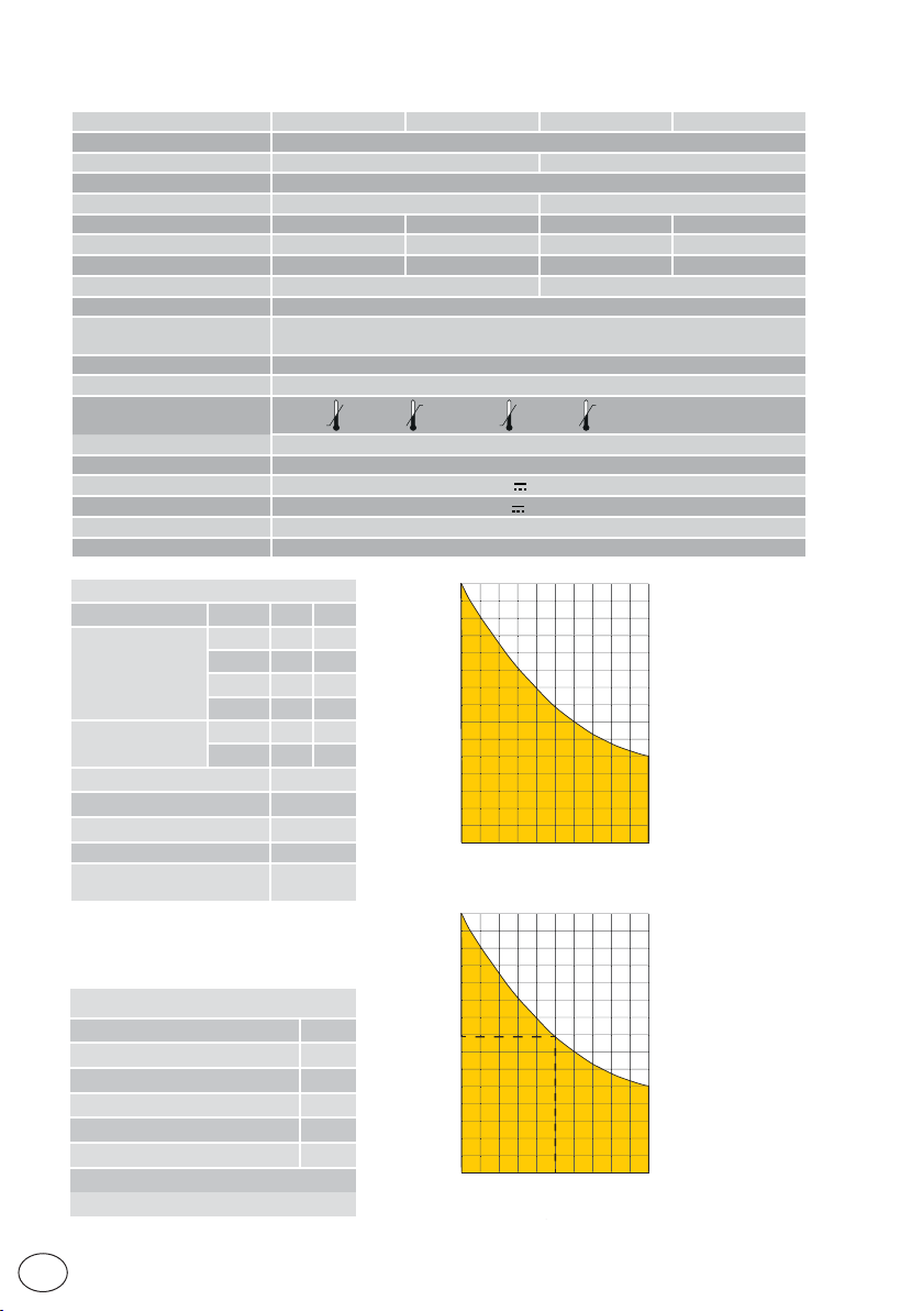
3. Technical specifications
Maximum stroke 12m
Maximum gate weight 400Kg 600Kg
Gate speed 0,1÷0,3 m/s
Thrust 200N nominal, 600N start-up 300N nominal, 800N start-up
Power supply 230 V~ 50/60Hz 120 V~ 50/60Hz 230 V~ 50/60Hz 120 V~ 50/60Hz
Power absorption 0,45A 0,9A 0,6A 1,2A
Fuse T1A F2A F1,6A F3,15A
Power 100 W 130 W
Intermittence 80 cycles/day, 30 continuous cycles
Lifespan
Acoustic pressure LpA ≤ 70dB(A)
IP degree of protection 44
Usage temperature
Product size 300 x 260 x 195
Control panel LCU48
Motor output 24V
Power supply to accessories 24V
Radio frequency 433,92 MHz
Storable radio codes 100 / 200 vedi RO → MU → 20/10
Index of conditioning factors
>150Kg 10 -
Gate wing weight
>200Kg 20 10
>300Kg 30 20
>400Kg - 30
Gate wing width
>4m 20 10
>8m - 20
Wheel diameter <100mm 10
Saline environment 10
Safety edge installed 10
R1/R2 > default 10
VA/VC > default
OC/CB < default
Example of lifespan calculation for ION4
Gate wing weight>150Kg 10
Gate wing width> 4.5m 10
Dust 10
Safety edges installed 10
VA/VC > default 10
Total stress index 50
Estimated lifespan - 80,000 cycles
Estimated daily cycles 22 (for 10 years)
ION4 ION4J ION6 ION6J
From 50,000 to 150,000 cycles, depending on the conditions indicated in table
(see the product lifespan charts)
-20°C +55°C ( -35°C +55°C with active NIO)
10A max
0,3A max
150.000
ION4 ION6
10
140.000
130.000
120.000
110.000
100.000
90.000
80.000
cicli
70.000
cycles
60.000
50.000
40.000
30.000
20.000
10.000
0
0
102030
indice di gravosità
Index of conditioning factors
150.000
140.000
130.000
120.000
110.000
100.000
90.000
80.000
cicli
70.000
cycles
60.000
50.000
40.000
30.000
20.000
10.000
0
0
102030
Index of conditioning factors
indice di gravosità
405060
405060
90
70
80
100
90
70
80
100
IP2288EN
EN
6
Page 7
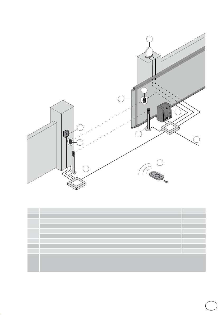
4. Standard installation
3
4
4
2
4
6
5
4
A
1
Rif. Description Cable
1 Remote control /
Flashing light 2 x 1 mm²
2
Antenna (integrated into the flashing light) coaxial 58 Ω
Key selector switch 4 x 0,5mm²
3
Digital combination wireless keypad /
4 Photocells 4 x 0,5 mm²
5 Actuator ION with control panel 3G x 1,5 mm²
6 Safety edge 2 x 0,5 mm²
Connect the power supply to a type-approved omnipolar switch, with a contact opening distance of at
least 3mm (not supplied).
A
The connection to the mains must follow an independent path, separate from the connections to the
control and safety devices.
IP2288EN
7
EN
Page 8
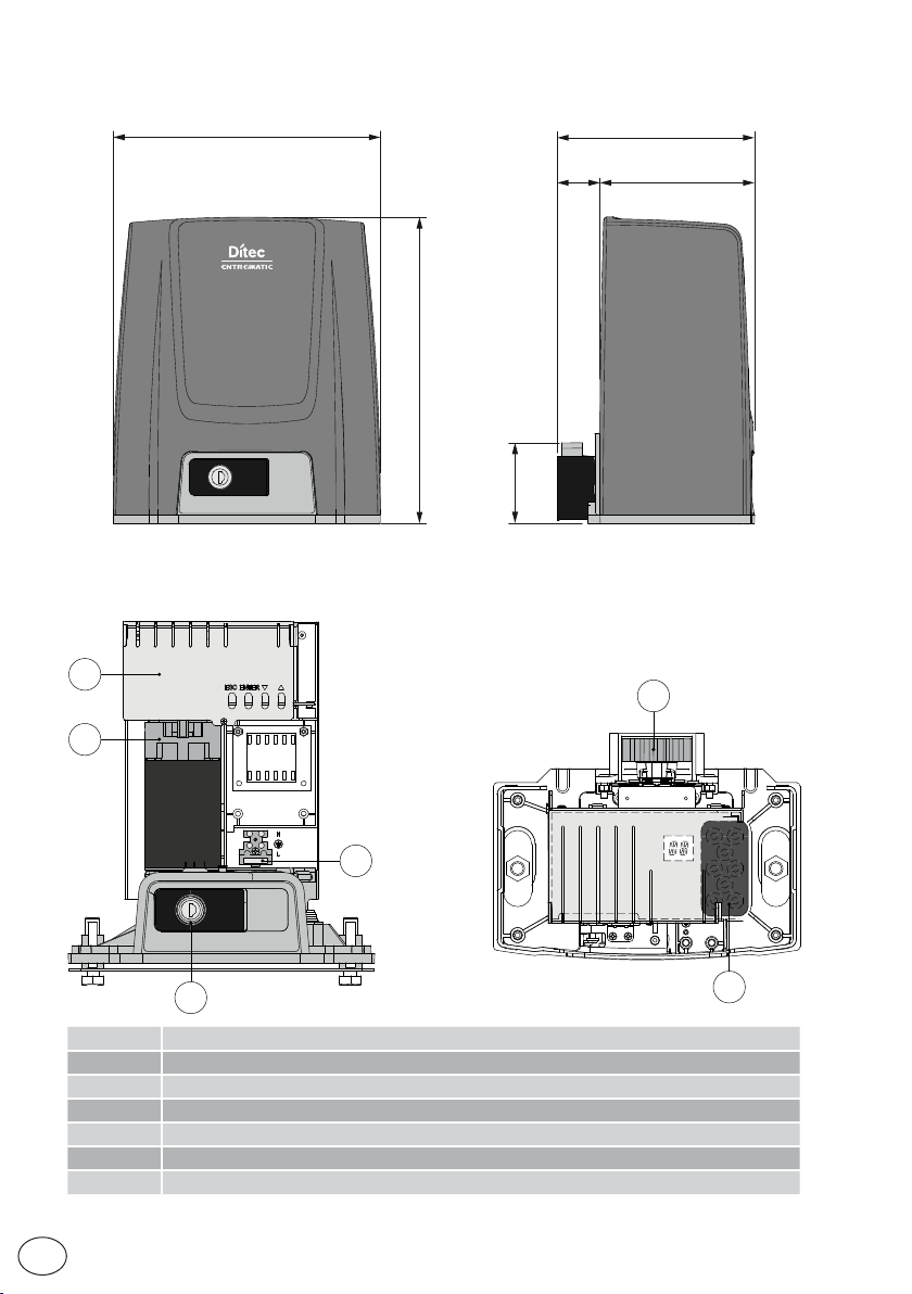
5. Dimensions
260
6. Main components
9
8
195
15540
300
80
11
EN
12
10
Rif. Descrizione
8 Motor
9 Control panel
10 Key release
11 Pinion
12 Cable inlet
13 Power supply terminal and fuse
8
12
IP2288EN
Page 9

7. Installation
The given operating and performance features can only be guaranteed with the use of DITEC ac-
cessories and safety devices.
Unless otherwise specified, all measurements are expressed in mm.
7.1 Preliminary checks
Check the stability of the wing (derailing and lateral falls) and the sliding wheels and that the upper
guides do not cause any friction.
The sliding guide must be securely fixed to the ground for the full length within doorway and must
have no irregularities that could hinder the movement of the wing.
The opening and closing stops must be fitted.
If the gate has slits, make sure they are covered to prevent shearing points or install active safety
edges on the columns.
Safety device should be installed at the end of the wing to reduce the collision force.
NB:
•Make sure that the gate can not exit the sliding guides and fall.
•Make sure that the protection system and any manual release function correctly.
7.2 Base plate position
Make a concrete base with the anchor ties and base plate embedded, which must be level and
clean and of the size indicated in the figure.
NB: if the concrete base has already been made, base plate can be fixed using M8 plugs
i
(not supplied).
IP2288EN
[*] CROSSCRI
[*] CROSSCRN2
X=40
X+20 [*]
160
OPENING
220
260
9
Ø80
40
min
90°
M12
low type
EN
Page 10
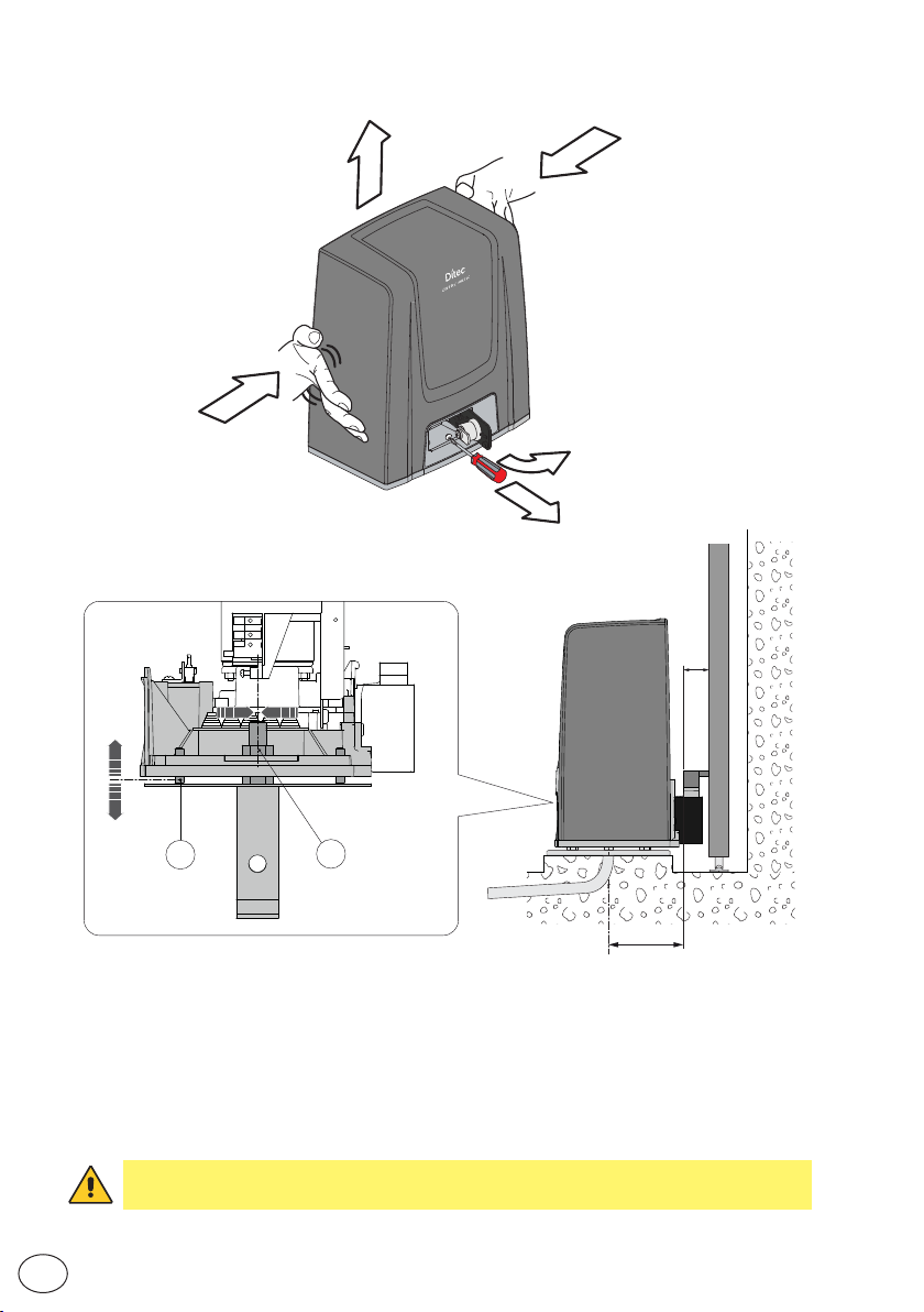
7.3 Gearmotor installation
4
3
3
1
2
X
-5 +20
±5
A
- Release the gearmotor [1] (see OPERATING INSTRUCTIONS). Loosen the front screw [2] and
remove the casing by pressing on its sides [3-4].
- Place the gearmotor on the base plate.
- Adjust the gearmotor horizontally by sliding it along the slots of the gearmotor base and vertically with
four levelling screws [A].
NB: during the vertical adjustment, keep the gearmotor slightly raised from the base plate so
that the rack can be fixed and subsequent adjustments are possible.
- After adjusting, fix the gearmotor using screws [B].
WARNING: The gearmotor must be suitably raised from the ground to avoid flooding.
Tighten the [B] screws using a tightening torque of 20-25 Nm.
B
100
10
EN
IP2288EN
Page 11
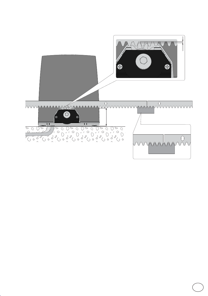
7.4 Rack installation
2÷3
min.80
- Release the gearmotor (see OPERATING INSTRUCTIONS) and open the gate.
- Place the rack against the pinion and sliding the gate manually fix it along its whole length.
NB: To make it easier to align the rods correctly, use a scrap piece of rack and rest it underneath
the junction point, as shown in the figure detail.
- Once fixed, vertically adjust the gearmotor to give a play of about 2 to 3 mm between the pinion
and the rack.
- Secure the gearmotor with the [B] screws using a tightening torque of 20-25 Nm.
- Slightly lubricate the rack and pinion after assembly.
Manually check that the gate slides evenly and without friction.
IP2288EN
11
EN
Page 12
7.5 Operation with virtual encoder
ION4-ION6 gearmotors do not require limit switches because they have a virtual encoder.
Mechanical opening and closing end stops must be installed.
The gate automatically slows when approaching the end stops.
WARNING: when the gate reaches the opening or closing limit stop, it reverses briefly to facilitate
manual release of the gearmotor.
7.6 Installation of optional accessories
7.6.1 Magnetic limit switches
The limit switch kit is used to stop the gate before it reaches the opening and closing
mechanical stops.
i
With a limit switch installed, slowdown is carried out at regulated power to overcome
possible friction.
For the installation of the limit switch kit, refer to the NES100FCM manual.
To position the limit switches, you can use the menu
configurations
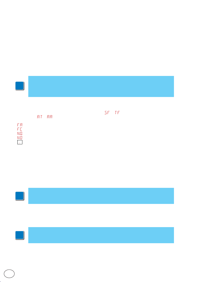
The display shows the status of the limit switches:
•
: opening limit switch configured and activated;
•
: closing limit switch configured and activated;
•
(both parts of display active): opening limit switch not configured and activated;
•
(no par t of display active): closing limit s witch not configured and activated;
•
(central part of display active): no limit s witch activated;
With the limit switches configured as STOP (FA = SX; FC = SX) the anti-violation function is activated. When
the auto mation stopped open or closed, if the gate ba cks off rel easing the limit swi tch, it is brou ght back into
position avoiding openings from external forces [energy saving must be disabled ES = OFF].
→ ).
→ (visible by activating the additional
7.6.2 Battery kit
For installation of the battery kit, refer to the SBU-IONSBU-BBU20-BBU65 (IP2254) manual.
The battery kit guarantees operation if there is a power cut.
For advanced control of battery-powered operation, refer to the
i
EM menu.
7.6.3 Remote release handle
For installation of the remote release handle, refer to the IONSBM and ASR2 manual.
The kit can be used to remotely release the gearmotor.
A microswitch guarantees safety.
i
When the handle is released, the control panel performs a reset
EN
IP2288EN
12
Page 13

8. Electrical connections
B
A
B
A
Before connecting the power supply, make sure the plate data correspond to that of the
mains power supply.
An omnipolar disconnection switch with a contact opening distance of at least 3mm must be
fitted on the mains supply.
Check there is an adequate residual current circuit breaker and overcurrent cutout upstream
of the electrical system.
For the po wer supply, use a H0 5RN-F 3G1.5 type electric cable. Connect it to terminals L (brown),
N (blue), (yellow/green) inside the automation.
NOTE: the maximum permisible section of the wire is AWG14 (2 mm2).
In order to comply with essential requirements of standards in force, reclose the cover once
the wires have been connected to the terminal.
In the external automation section, the connections to the mains power supply and any other low
voltage wires (230V) must be made on an independent channel separated from the connections
to the command and safety devices (SELV = Safety Extra Low Voltage).
The channel must penetrate the automation through the holes on the base plate by a few centimetres.
Make sure there are no sharp edges that may damage the power supply cable.
Make sure the mains power wires (230V) and the accessor y wires (24V) are separated. The cables
must be double insulated. Unsheathe them in line with the relative connection terminals, and
use cable fasteners (see ref. A) or straps (not supplied by us) to hold them in place.
IP2288EN
13
EN
Page 14
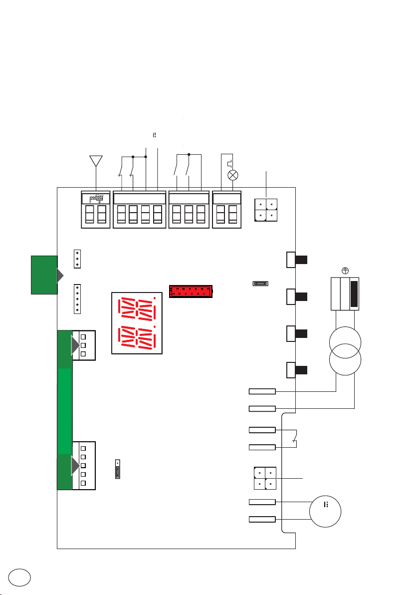
9. LCU48 card
Antenna
Sicurezza in chiusura
Closing safety device
Antenna
Arresto di sicurezza
Safety stop
+
-
24V output
Uscita 24 V
Apertura parziale
Partial opening
Passo-passo
Step-by-step
Lampeggiante
Flashing light
kit
SBU
SBU battery
Kit batteria
6ZENRS
ZENPRS
PLUG-IN BOARD
SCHEDA AD INNESTO
8
016
30
520
+-LP
BAT
Power supply
UPDOWN
C
O
RDX
M
JR1
ENTERESC
Alimentazione
LN
Fuse
Fusibile
Transformer
Trasformatore
24V~
AUX
Microswitch
SSW
Release
microswitch
di sblocco
LSW
JR5
130
Limit switch
Finecorsa
NES100FCM
NES100FCM
EN
14
M+ M-
24V
Motor
Motore
IP2288EN
Page 15

10. Using of the menus
NB: pressure on the keys may be quick (less than 2 s) or prolonged (longer than 2 s).
Unless specified otherwise, quick pressure is intended.
i
To confirm the setting of a parameter, prolonged pressing is necessar y.
10.1 Switching the display ON and OFF
The procedure to switch on the display is as follows:
• press the ENTER key
• the display functioning check starts
• the first level menu is displayed
The procedure to switch off the display is as follows:
• press the ESC key
NB: there is no automatic exit from the WZ quick configuration menu. For all the other menus,
the display switches off automatically after 60 seconds of inactivity.
10.2 Navigation keys
• The simultaneous pressing of the ↑ and ENTER keys produces an opening command.
• The simultaneous pressing of the ↓and ENTER keys produces a closing command.
• The simultaneous pressing of the ↑ and ↓ keys produces a POWER RESET command (power supply interruption and automation restart).
• Keep the UP ↑ or DOWN ↓ key pressed to begin fast menu scrolling.
To set a parameter, select the desired value and press ENTER for 2 seconds to save.
Example: setting of 30 seconds for parameter TC
x 2 s
• In some menus, the parameter measurement unit can be viewed by pressing the ENTER key
once the value has been displayed.
IP2288EN
15
EN
Page 16
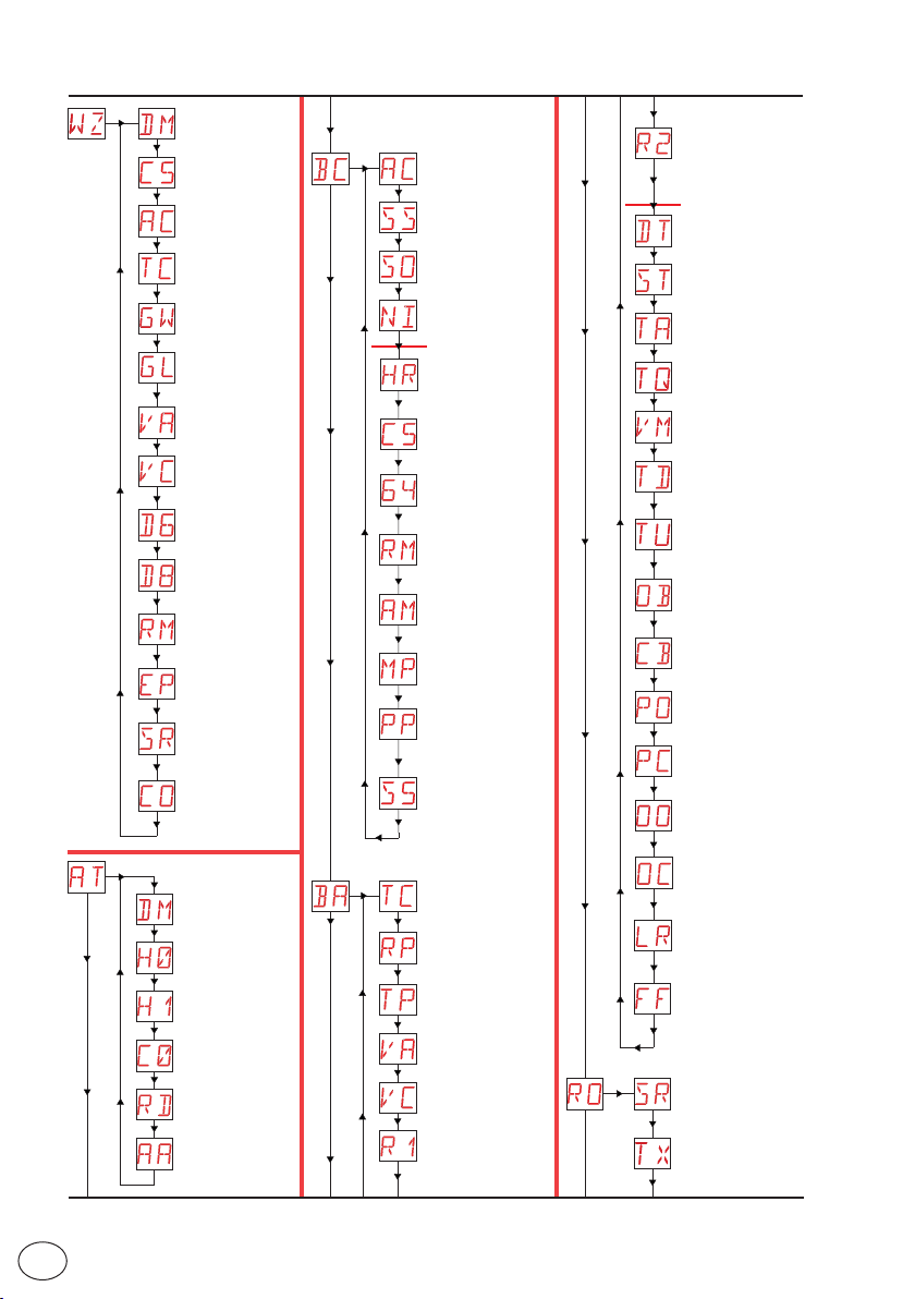
10.3 Menu map
Opening direction
RT= right
LF= left
Contact 1-5 command
operation
Automatic closure
enabling
Quick configuration menu
Automatic closing time
Gate weight
Gate length
Opening
speed
Closing speed
Selection of device connected to terminals 1-6
Selection of device connected to terminals 1-8
Radio receiver
operation
Setting of radio coded
messages
Remote control
storage
Confirm configuration
Standard settings
Automatic closure
enabling
Automation status
at switch-on
Reversal safety
operation
Activation of antifreeze system NIO
*
Activation of "operator
present" function
Contact 1-5 command
operation
Operation of safety
stop/closure command
Radio receiver
operation
AUX1 board
operation
Start-up at maximum power
Setting of step-by-step
sequence via command 1-5
Duration of STOP in
step-by-step sequence
via command 1-5
Thrust adjustment on
obstacles and closure
current
Obstacle recognition
*
time adjustment
Start-up time
adjustment
Adjustment of acceleration
time on opening
Adjustment of acceleration
time on closure
Initial movement
speed
Deceleration time adjustment during opening
Deceleration time adjustment during closure
Deceleration distance on
opening
Deceleration distance on
closing
Adjustment of approach
speed during opening
Adjustment of approach
speed during closure
Obstacle detection limit
during opening
EN
Automatic configurations
Opening direction
RT= right
LF= left
Residential 0
Residential 1
Condominium 0
Reset general
settings
Activation of advanced
parameters menu
Standard adjustments
Automatic closing time
Partial opening measurement adjustment
Automatic closing
time after partial
opening
Opening
speed
Closing speed
Thrust adjustment on
obstacles and opening
current
16
Wireless
operations
Obstacle detection limit
during closure
Electric lock release time
Function of output
+LP-
Remote control
storage
Visualisation of number of
remote controls stored
IP2288EN
Page 17
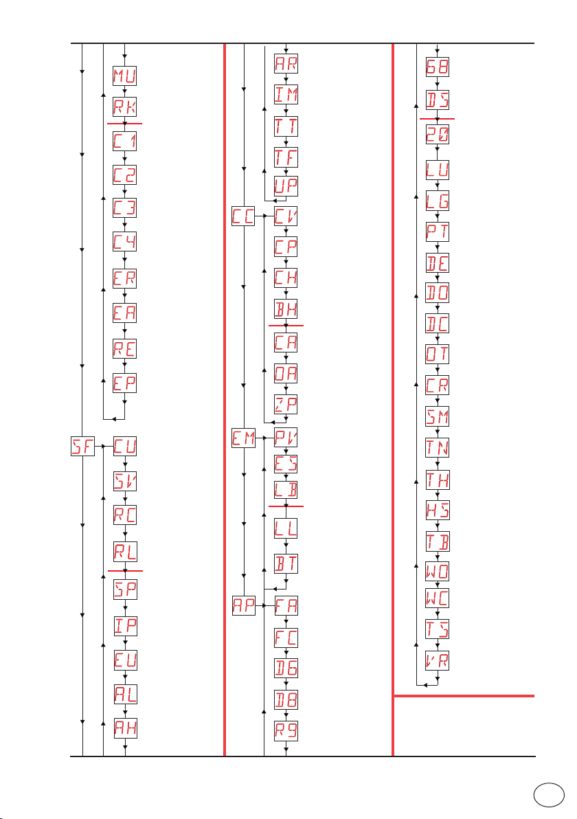
IP2288EN
Maximum number of
remote controls that can
be stored in the integrated
memory
Menu navigation via remote
control keypad
Selection of function CH1 of
the stored remote control
Selection of function CH2 of
the stored remote control
Selection of function CH3 of
the stored remote control
Selection of function CH4 of
the stored remote control
Deletion of a remote control
Total memory
deletion
Setting of memory opening
via remote control
Setting of radio coded
messages
Control panel firmware
version
Configuration storage
Special functions
Configuration loading
Loading of last configuration set
Password setting
Password insertion
Deletion of user settings
Alarm counter
Alarm log
*
*
Cycle countersEnergy management
Advanced parameters
Alarm reset
Motor current visualisation
Visualisation of maximum
and minimum temperatures recorded
Limit switch test. Visualises FA/FC only (N.O. / NO
if they are not configured)
Firmware update
Total number of
operations
Partial number of
operations
Power supply hours
Power supply hours
via battery
*
Maintenance alarm
setting
Visualisation of maintenance alarm mode
Reset of partial operations
counter
Power supply via solar
panels
Energy saving
Signal for batteries
almost flat
*
Voltage threshold for indicating when the batteries
are almost flat
Battery mode
Selection of opening
limit switch mode
Selection of closure
limit switch mode
Selection of device connected to terminals 1-6
Selection of device connected to terminals 1-8
Configuration of input 1-9
Selection of device connected to terminals 1-6
and 1-8
Display mode
Partial opening com-
*
mand of terminal 1-20
Courtesy light switch-on
time
Switch-on time for
independently commanded
courtesy light
Fixed partial opening
Duration of disengagement
after edge intervention
Duration of disengagement
on stop during opening
Duration of disengagement
on stop during closure
Selection of type of
obstacle
Stroke estimate correction
Selection of operating
mode for device connected
to terminals 1-6
NIO intervention temperature and automatic ramps
High temperature protection enable
Automatic ramp adjustment
Visualisation of internal
panel temperature
Setting pre-flashing time
on opening
Adjustment of approach
speed during closure
Renew automatic closing
time after safety device
release
Learning speed setting
Additional configurable pa-
*
rameters available with
AT → AA enabled.
17
EN
Page 18
11. Product start-up
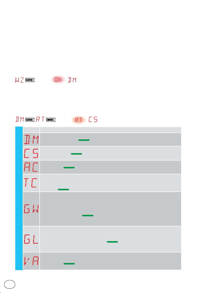
For rapid configuration of the product, use the WIZARD (WZ) menu or the second level AT (Automatic Configurations) menu [See par. 15.2].
For detailed, customised configuration, use the main menus BC, BA, RO, SF, CC, EM, AP.
11.1 WZ configuration wizard menu
To access the WZ configuration wizard menu:
Hold down the ENTER button for 2 seconds.
When OK has stopped flashing, DM, the first menu parameter, is displayed.
for 2 sec.
To set a parameter:
1. Press ENTER to access the configuration items.
2. Scroll UP/DOWN the possible options.
3. To confirm, press the ENTER button for 2 seconds. The selected value flashes and when it has
finished, the next parameter appears.
for 2 sec.
Display Description
DM - Selection of opening direction (looking at the automation from the side being examined)
• RT: opens to the right (default)
• LF: Opens to the left
C5 - Operation of command associated with contact 30-5
• 1-5: step-by-step (default)
• 1-3: Opening
AC - Enabling of automatic closure
• ON: enabled (default)
• OF: disabled
TC - Setting of automatic closing time [seconds]
[N.B.: only visible if you have selected AC = ON in the previous step]
• from 0” to 59” with intervals of 1 second.
• - from 1’ (default) to 2’ with intervals of 10 seconds.
GW - Selection of gate weight.
The selected value sets parameters R1 and R2 to adjust the maximum thrust current of the
motor.
• LG: up to 200 kg → (R1=R2=30%)
WZ - Wizard
• MG: between 200 kg and 300 kg for ION4 and ION4J, between 200 kg and 400 kg for ION6
and ION6J → (R1=R2=50%) (default)
• HG: between 300 kg and 400 kg for ION4 and ION4J; between 400 kg and 600 kg for ION6
and ION6J → (R1=R2=70%)
GL - Selection of gate length
The selected value sets parameters OB and CB for adjusting the deceleration space
• 02: between 0 and 2 m → (OB=CB=50cm)
• 04: between 2 and 4 m → (OB=CB=60cm) (default)
• 06: between 4 and 6 m → (OB=CB=70cm)
• >6: over 6 m → (OB=CB=80cm)
VA - Selection of opening speed
• LO: 15 cm/s
• ME: 20 cm/s (default)
• HI: 25 cm/s
IP2288EN
EN
18
Page 19
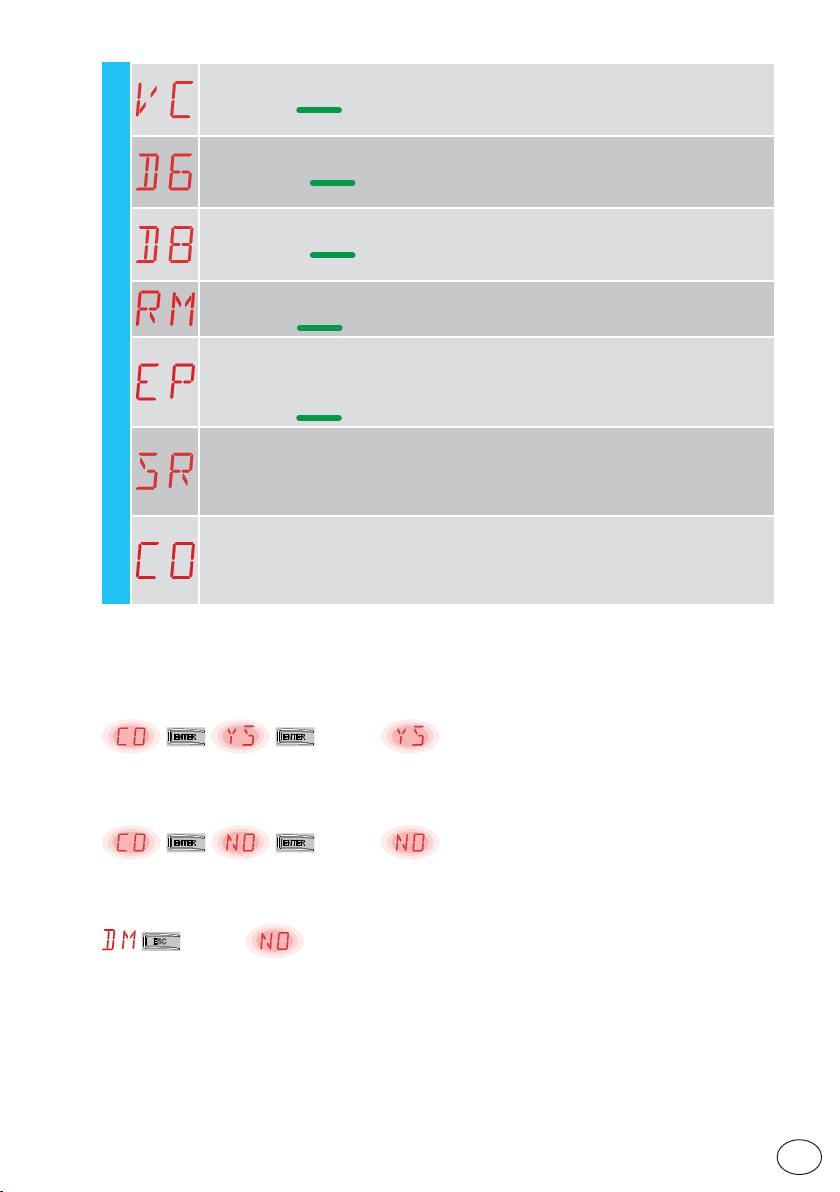
VC - Selection of closing speed
• LO: 15 cm/s
• ME: 20 cm/s (default)
• HI: 25 cm/s
D6 - Selection of device connected to terminals 1-6
• NO: none
• PH: photocells
For other options, see the specific menu.
D8 - Selection of device connected to terminals 1-8
• NO: none
• PH: photocells (default)
For other options, see the specific menu.
RM - Radio receiver operation
• 1-3: Step-by-step
• 1-5: opening (default)
EP - Setting the coded area messages
If the possibility to receive coded messages is enabled, the control panel will be compatible
with remote controls of the “ENCRYPTED” type.
WZ - Wizard
• ON: enabled
• OF: disabled (default)
SR - Remote control storage
When you press ENTER, SR starts to flash and you can associate the desired buttons. Once
OK is displayed, SR starts to flash again and you can associate the next button.
To quit, press ESC or ENTER for 2 seconds and go on to the next item.
NB: if NO flashes on the display, the remote control may already be stored.
CO - Saving of parameters
Here you can save the parameters that have previously been set.
• YS: to save and perform a card RESET
• NO: to quit without saving and go back to a blank screen (central part only)
NB: the CO item and YS/NO sub-menus flash constantly.
(default)
To save the configuration:
In the CO parameter select YS (yes) and press the ENTER button for 2 seconds.
When the configuration has been saved, a power reset is automatically performed on the card.
for 2 sec.
To quit without saving changes:
In the CO parameter select NO and press the ENTER button for 2 seconds.
for 2 sec.
Or: from any main parameter, press the ESC button for 2 seconds.
Example
for 2 sec.
NOTES
• The set values are only stored on the card if they are saved using the CO parameter.
• The CO parameter and YS/NO options flash constantly.
• When a configuration item is confirmed, it automatically moves on to the next parameter.
• You can scroll through the menu parameters using the UP/DOWN buttons.
• There is no automatic timeout function to quit.
IP2288EN
19
EN
Page 20
12. Commands
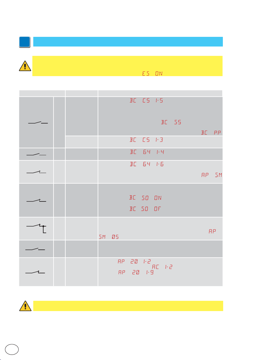
You are advised to read paragraph 15 for all the details about the possible adjustments.
i
WARNING: terminal 30 (common positive for commands) has the same functions as terminal 1, so
the commands visualised on the display are indicated with 1-5, 1-3, etc.
It is dif ferent from terminal 1, however, because of the maximum current that can be dispensed
and it is also active when the control panel is in standby
Command Function Description
When selecting
tivates a sequential opening or closing operation: opening-stopclosing-opening.
WARNING: if automatic closure is enabled, the duration of the
stop can be defined by selecting
The “opening-stop-closing-opening” sequence can be changed
to “opening-stop-closing-stop-opening” by selecting
When selecting
tivates an opening operation.
When selecting
a closing operation.
When selecting → → , opening of the safety contact
stops and prevents any movement.
NB: to set different safety contact functions, see the
parameter settings.
The opening of the safety contact trigger s a rever sal of the
movement (reopening) during the closing operation.
When selecting
vents any operation when the automation is idle.
When selecting
prevents closure when the automation is idle.
The opening of the safety contact stops and prevents any movement.
NB: oper ation corresponds to that of contact 1-6 with
→ .
The closure of the contact activates a partial opening operation.
Once the automation stops, the partial opening control performs
the opposite operation to the one performed before the stop.
Selecting → → , the permanent closure of the contact
enables automatic closure if
Selecting
causes the movement to stop.
NB: the flashing light flashes.
→ → , the opening of the safety contact
30
1
1
1
1
8
1
1
STEP-BY-STEP
5 NO
OPENING
6 NO CLOSURE
NC SAFET Y STOP
6
CLOSING
NC
NC
NC
SAFETY
DEVICE
CLOSING/
OPENING
SAFETY
DEVICE
PARTIAL
OPENING
AUTOMATIC
CLOSURE OR
STOP
8
6
20 NO
20
→ .
→ → , the closure of the contact ac-
→ .
→ → , the closure of the contact ac-
→ → , closing the contact activates
→ → , the opening of the contact pre-
→ → , the opening of the contact only
→ .
→ .
→
→
EN
WARNING: make a jumper for all NC contacts if not used, or deactiv ate them via the relative menu.
Terminals with the same number are equal.
IP2288EN
20
Page 21
12.1 SOFA1-SOFA2 or GOPAVRS self-controlled safety edge
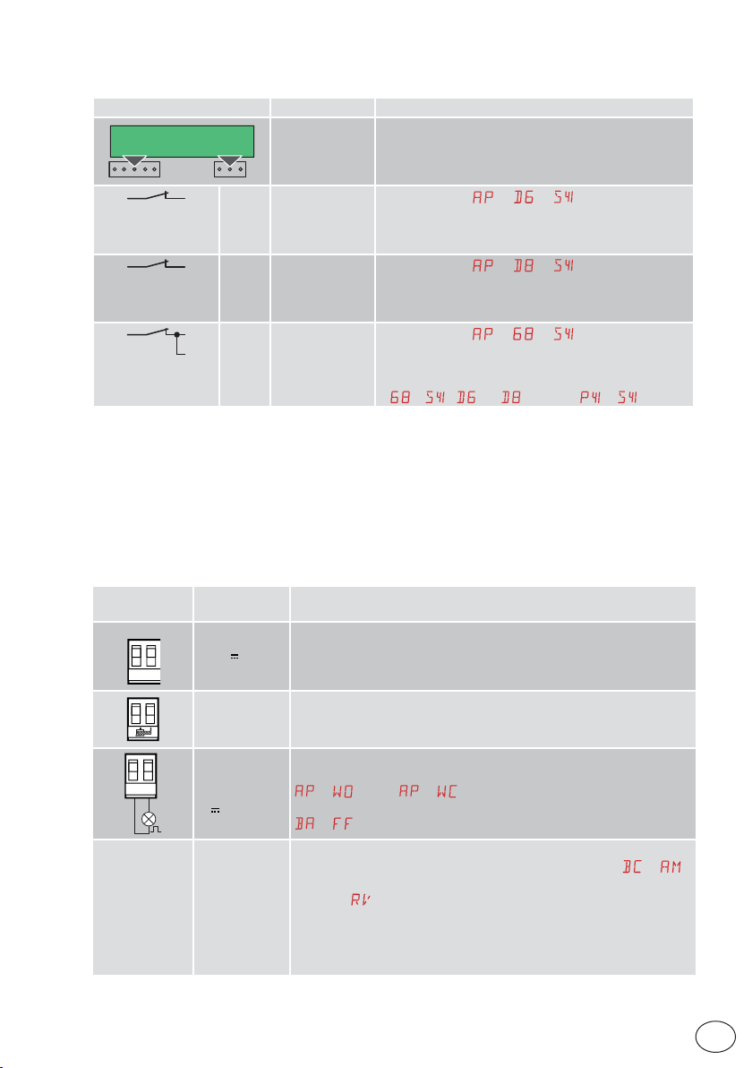
Command Function Description
SOFA1-SOFA2
GOPAV
1
1
1
8
6
NC SAFETY STOP
8
NC
6
NC
SAFETY TEST
CLOSURE
SAFETY DEVICE
CLOSING/
OPENING
SAFETY DEVICE
Inser t the SOFA1-SOFA2 or GOPAVR S device in the slot
for plug-in boards AUX1 or AUX2.
If the test fails, an alar m message appears on the
display.
When selecting
conta ct of the safet y device to te rminals 1-6 on the control panel (in ser ies with the photocell output contact,
if installed).
When selecting
conta ct of the safet y device to terminal s 1-8 on the control panel (in ser ies with the photocell output contact,
if installed).
When selecting
contact of the safety device to terminals 1-6-8 on the
control panel (in series with the photocell output contact, if installed).
If
→ , and cannot be or .
→ → , connec t the output
→ → , connect the output
→ → , connect the output
13. Outputs and accessories
IP2288EN
Output
0-1
+LP-
AUX
Value of
accessories
+
24V / 0.3A
GOL148REA
FLM
FL24
24V / 25W
SOFA1-SOFA2
GOPAVRS
LAB9
BIXR2
BIXPR2
LAN7S
Power supply to accessories
Output for power supply to external accessories.
NB: the maximum absorption of 0.3A corresponds to the sum of all
terminal s 1.
If the ZENPRS radio receiver is used (868.35 MHz), connect the supplied
antenna wire (90mm).
Flashing light
The pre-flashing settings can be selected from the third level menu
→ and/or → .
To modify the oper ating mode of the LP output, refer to the selection
→ .
The control panel has a slot for plug-in command and safety cards.
The action of the control card can be defined by selecting
When using slot-in radio boards, remove the RDX module. The display
will show
WARNING: the plug-in board must be inser ted and removed with the
power supply disconnected.
.
Description
→ .
21
EN
Page 22
Output
RDX
COM
BAT
Value of
accessories
6ZENRS
ZENPRS
BIXM R2
SBU
Description
The control panel is fitted with a housing for modules of the 6ZENRS
radio receiver type (433.92 MHz).
Can be replaced with a module of the ZENPRS radio receiver type (868.35
MHz).
When using slot-in radio boards, remove the RDX module. The display
will show
WARNING: the modules must be inserted and removed with the power
supply disconnected.
COM - This allows the functioning configur ations to be saved using the
function
The saved configurations can be recalled using the function
COM - The storage module allows the remote controls to be stored. If the
control panel is replaced, the storage module being used can be inserted
in the new control panel.
WARNING: the storage module must be inserted and removed with
the power supply disconnected, and paying attention to the positioning
direction.
BAT - Battery-powered operation.
The batteries are kept charged when the power supply is on. If the power
supply is off, the panel is powered by the batteries until the power is reestablish or until the battery voltage drops below the safety threshold.
The control panel turns off in the last case. WARNING: the batteries must
always be connected to the control panel for charging. Periodically check
the efficiency of the batteries.
NB: the operating temperature of the rechargeable batteries is from
+5°C to +40°C.
For advanced control of battery-powered operation, refer to the menu
.
→ .
→ .
.
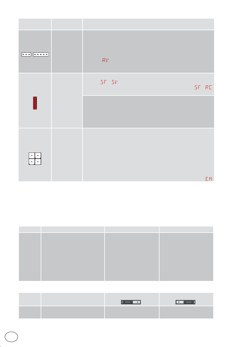
14. Jumper setting
Jumper Description OFF ON
JR1 Display mode selection. Display mode.
Jumper Description
JR5 Selection of power supply - auxil-
iary board.
EN
Only the values and parameters present can be
displayed.
130
AUX1 powered from 0-1.
(default)
22
Maintenance mode.
Only the values and parameters present can be
displayed and modified.
Activated maintenance
mode is indicated by the
permanent switching on of
the right-hand point on the
display.
130
AUX1 powered from 0-30.
IP2288EN
Page 23
15. Adjustments
NB: depending on the type of automation and control panel, some menus may not be
i
available.
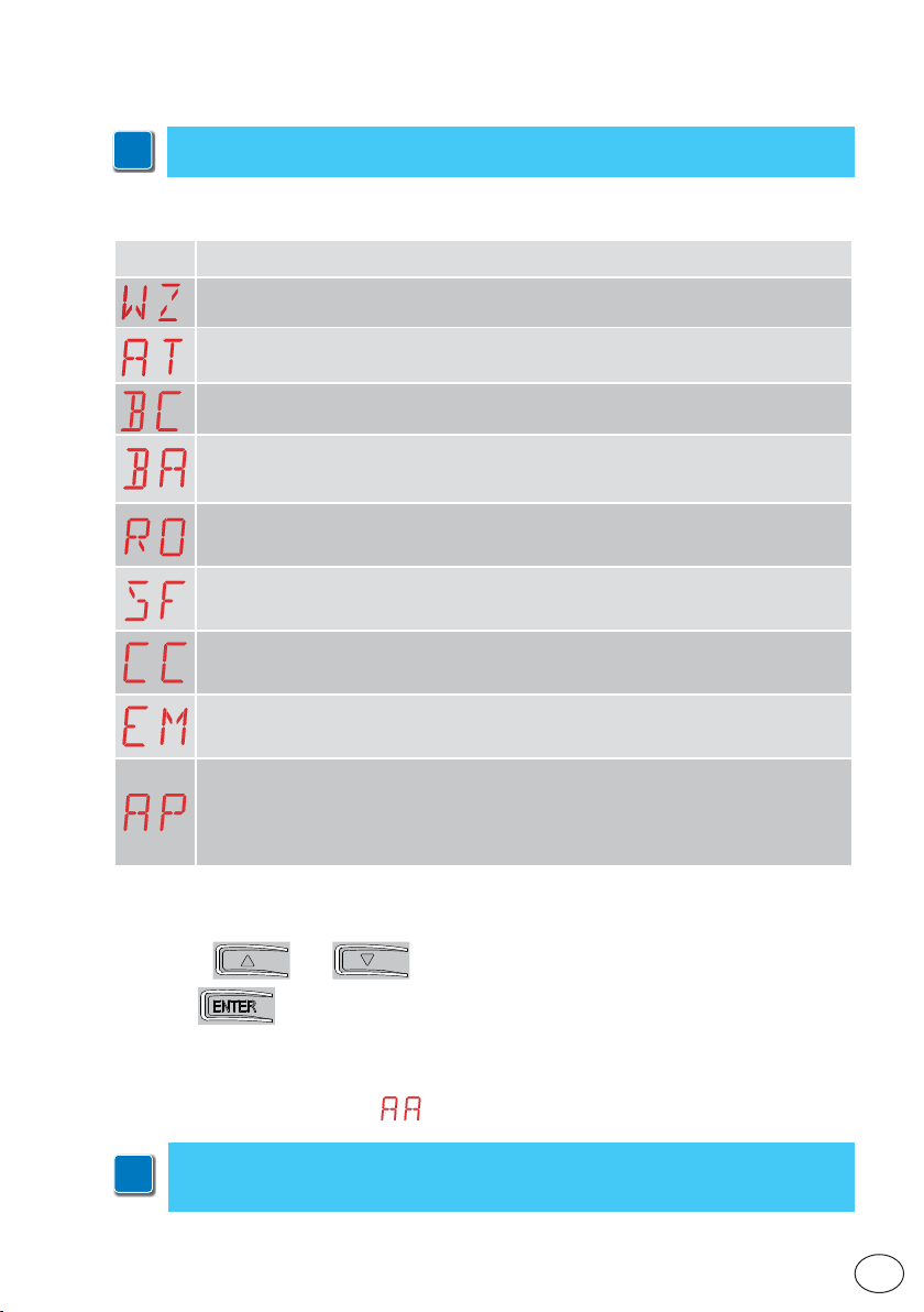
15.1 Main menu
Display Description
WZ - Wizard
Quick configuration menu
AT - Automatic Configurations.
The menu allows you to manage the automatic configurations of the control panel.
BC - Basic Configurations.
The menu allows you to display and modify the main settings of the control panel.
BA - Basic Adjustments.
The menu allows you to display and modify the main adjustments of the control panel.
NB: some settings require at least three operations before they are set correctly.
RO - Radio Operations.
The menu is used to manage the r adio functions of the control panel (alarm management,
diagnostics enabling, FW updating).
SF - Special Functions.
The menu allows you to set the password and manage the special functions in the control
panel.
CC - Cycles Counter.
The menu allows you to display the number of operations carried out by the automation and
manage the maintenance interventions.
EM - Energy Management.
The menu allows you to display and modify the energy saving settings and adjustments
(Green Mode and battery management).
AP - Advanced Parameters.
The menu allows you to display and modify the advanced settings and adjustments of the
control panel (limit switch mode, selection of devices connected to the terminals, disengagement dur ation adjustments, flashing light adjustments, etc.).
NB: some settings require at least three operations before they are set correctly.
From the main menu you can access the second level menu as follows:
• use the and keys to select the required function
• pres s
to confirm
After confirming the selection, you access the second level menu.
For each function of the main menu, there are also additional configurations that
can be viewed by enabling the
NB: to check if the parameters have actually been modified, quit the relative parameter and then access it again.
i
IP2288EN
The modifications will take effect from the next operation.
function (see the following paragraph).
23
EN
Page 24
15.2 Second level menu - AT (Automatic Configurations)
Display Description
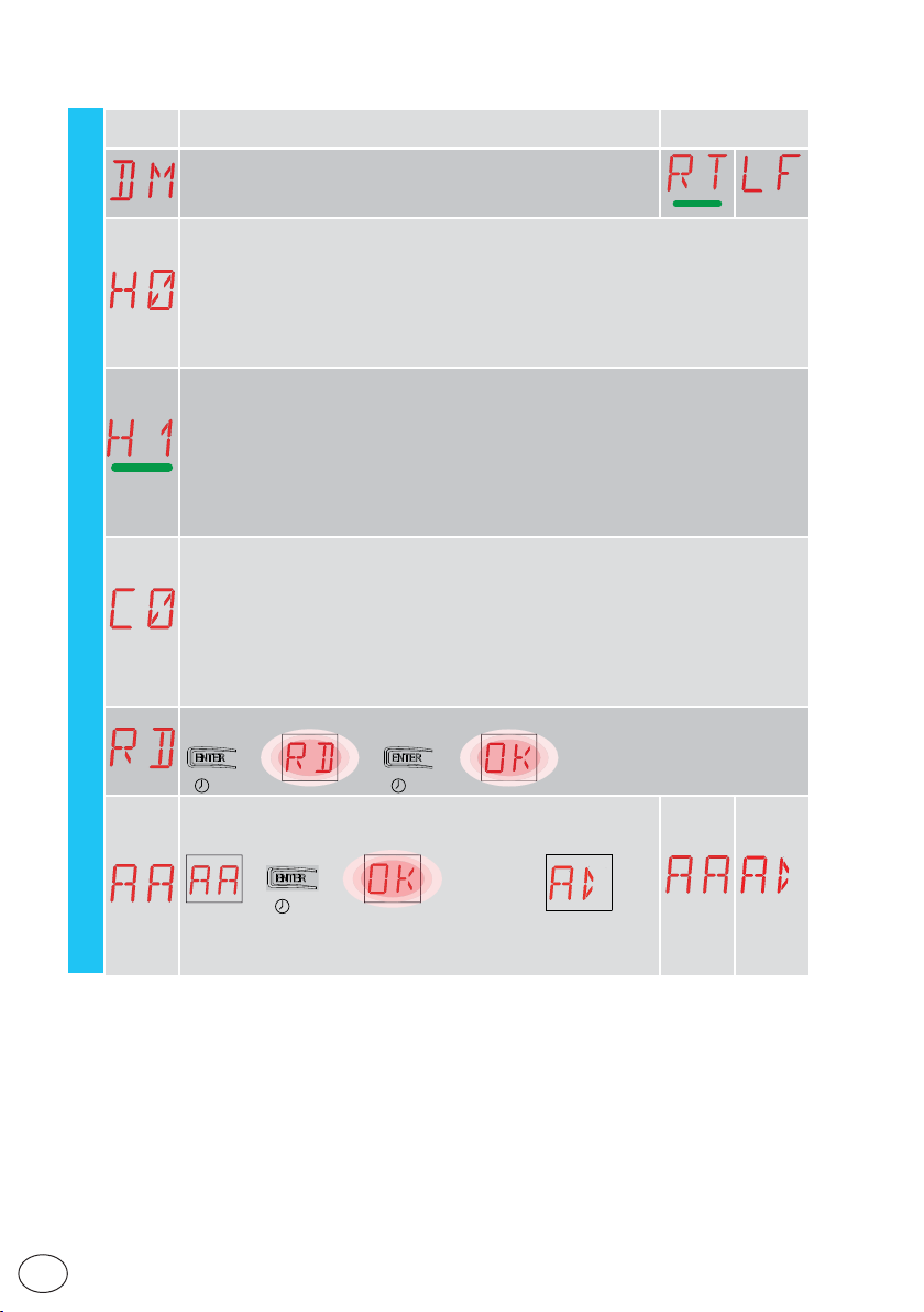
DM - Direction mode
RT-opens to the right
LF-open to the left
H0 - Predefined setting, residential use 0
This selection loads predefined values for certain standard parameters:
AC - enabling of automatic closing : 1-2
C5 - step-by-step/opening command operation : Step-by-step
RM - remote control operation : Step-by-step
AM - AUX plug-in board operation : Step-by-step
SS - Selection of automation status at star t-up : open
H1 - Predefined setting, residential use 1
This selection loads predefined values for certain standard parameters:
AC - enabling of automatic closing : enabled
TC - set ting of automatic closing time : 1 minute
C5 - step-by-step/opening command operation : Step-by-step
RM - remote control operation : Step-by-step
AM - AUX plug-in board operation : Step-by-step
SS - Selection of automation status at star t-up : closed
C0 - Predefined setting, condominium use 0
This selection loads predefined values for certain standard parameters:
AC - Enabling of automatic closure : enabled
TC - set ting of automatic closing time : 1 minute
C5 - step-by-step/opening command operation : Opening
RM - remote control operation : Opening
AM - AUX plug-in board operation : Opening
SS - Selection of automation status at star t-up : closed
AT - Automatic configurations
RD - Resetting of general settings (SETTINGS RE SET)
→→
2” 2”
AA - Activation of additional configurable parameters for each function of the main menu.
Selections
available
→
EN
→
2”
After activation you can scroll through the third level menus.
The third level menus are activated for 30 min.
24
IP2288EN
Page 25
15.3 Second level menu - BC (Basic Configurations)
Display Description
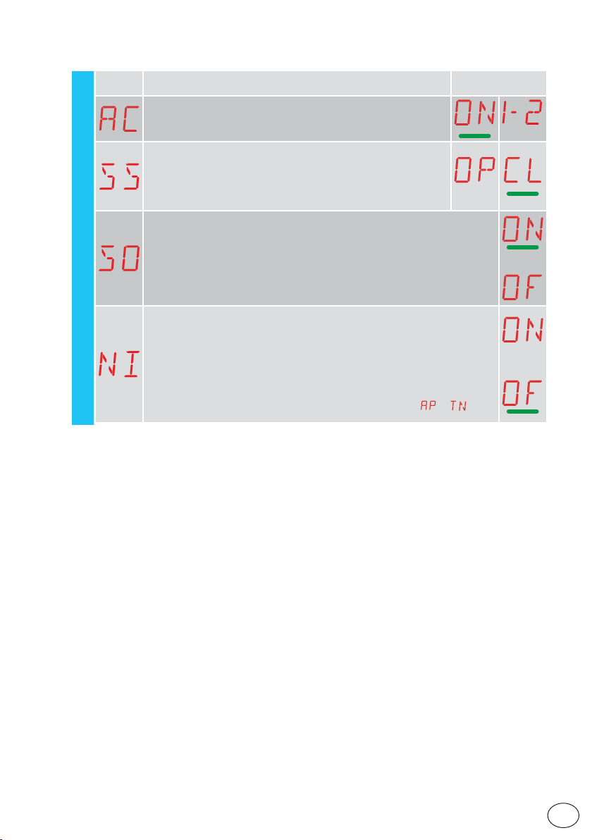
AC - Enabling of automatic closure
ON - Enabled
1-2 - Dependent on input 1-2
SS - Selection of automation status at star t
OP - Open
CL - Closed
Indicates how the control panel considers the automation at the
time of switch-on, or after a POWER RESE T command.
SO - Enabling of reversal safety contact functioning
ON - Enabled
OF - Disabled
When enabled (ON) with the automation idle, if the contact 1-8 is open, all
operations are prevented.
When disabled (OF) with the automation idle, if the contact 1-8 is open, opening
operations are permitted.
NI - Enabling of NIO electronic anti-freeze system
ON - Enabled
BC - Basic configurations
OF - Disabled
When enabled (ON), it maintains the efficienc y of the motor even at low ambi-
ent temperatures.
NB: for correct operation, the control panel must be exposed to the same ambient temperature as the motors.
The intervention temperature for NIO can be set by selecting
→ .
Selections
available
IP2288EN
25
EN
Page 26
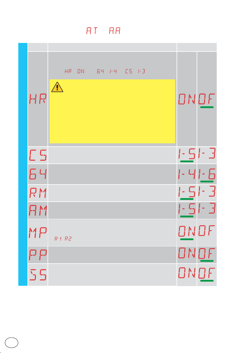
15.3.1 Additional BC level parameters that can be configured
(available with → enabled)
Display Description
HR - Enabling of "operator present" function
ON - Enabled
BC
OF - Disabled
NB: Set
WARNING:
• If the OPER ATOR PRESENT function is activated, make sure that noone is near the automation when an opening or closing command is
given.
• The actuation device for the OPERATOR PRESENT function must be
placed within the visibility of the guided part but away from the moving
parts.
It must also be in stalled at a minimum hei ght of 1.5 m and be pla ced out
of the public’s reach.
C5 - Operation of command associated with contact 3 0-5
1-5 - Step-by-step
1-3 - Opening
64 - Functioning of safety stop/closing command.
→ only if → and → .
1-4 - Closing
1-6 - Safety stop
RM - Radio receiver operation
1-5 - Step-by-step
1-3 - Opening
AM - Operation of AUX1 plug-in control board
1-5 - Step-by-step
1-3 - Opening
MP - Star t-up at maximum power
ON - During star t-up it increases the thrust on obstacles to maximum
OFF - During start-up, the thrust on obstacles is the one adjusted
by
- .
Selections
available
EN
PP - Setting step-by-step sequence from command 1-5.
ON - Opening-Stop-Closing-Stop-Opening
OF - Opening-Stop-Closing-Opening
S5 - Duration of STOP in step-by-step sequence from command
1-5.
ON - Permanent
OF - Temporary
IP2288EN
26
Page 27
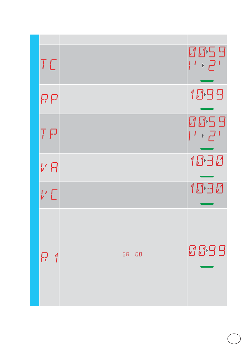
15.4 Second level menu - BA (Basic Adjustment)
Display Description
TC - Set ting of automatic closing time [s]
It is set with dif ferent inter vals of sensitivity.
• from 0” to 59” with intervals of 1 second
• from 1’ to 2’ with intervals of 10 seconds
RP - Adjustment of partial opening measurement [%]
Adjusts the percentage of operation in relation to the total opening
of the automation.
10 - Minimum
99 - Maximum
TP - Setting of automatic closing time after partial opening [s]
It is set with dif ferent intervals of sensitivity.
• from 0” to 59” with intervals of 1 second
• from 1’ to 2’ with intervals of 10 seconds
VA - Opening speed [cm /s]
VC - Closing speed [cm/s]
BA - Basic adjustment
R1 - Adjustment of thrust on obstacles and motor current during
opening. [%]
The control panel is fitted with a safety device which, when it detects an obstacle:
- stops the movement and, if outside the obstacle detection
area, performs a disengagement.
The obstacle detection area during opening is determined by the
type of limit switch installed. If there is no limit switch, it is determined according to the selection
00 - Minimum thrust
99 - Maximum thrust
→ .
Selections
available
1’00”
30
30
20
20
50
IP2288EN
27
EN
Page 28
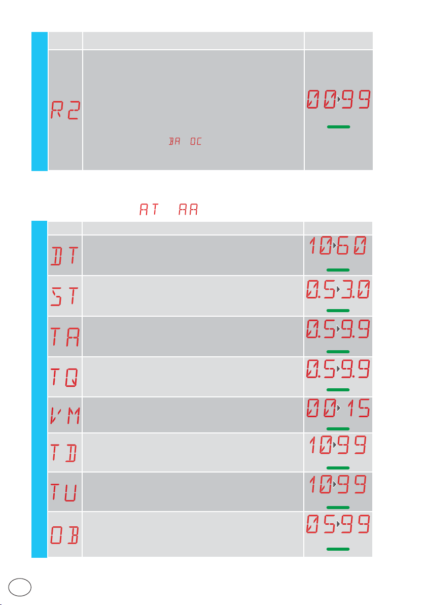
Display Description
R2 - Adjustment of thrust on obstacles and motor current during
closure. [%]
The control panel is fitted with a safety device which, when it detects
an obstacle:
- reverses the movement during closure operations outside the limit
area for detecting obstacles;
- stops the movement during closure operations within the limit area
for detecting obstacles.
The obstacle detection area during closure is determined by the type
of limit switch installed. If there is no limit switch, it is deter mined
according to the selection
00 - Minimum thrust
BA - Basic adjustment
99 - Maximum thrust
→ .
Selections
available
50
15.4.1 Additional BA level parameters that can be configured
(available with
Display Description
DT - Adjustment of obstacle recognition time [s/100]
10 - Minimum
60 - Maximum
NB: the parameter is adjusted in hundredths of a second.
ST - Adjustment of start time [s]
0.5 - Minimum
3.0 - Maximum
TA - Adjustment of acceleration time during opening [s]
0.5 - Minimum
9.9 - Maximum
TQ - Adjustment of acceleration time during closure [s]
0.5 - Minimum
9.9 - Maximum
BA
VM - Initial movement speed [cm/s]
00 - Minimum
15 - Maximum
TD - Adjustment of deceler ation time during opening [%]
Regulates the slope of the deceleration ramp during opening.
10 - Minimum
99 - Maximum
TU - Adjustment of deceleration time during closure [%]
Regulates the slope of the deceleration ramp during opening.
10 - Minimum
99 - Maximum
OB - Adjustment of deceleration distance during opening. [cm]
Indicates the distance from the end of the opening stroke for the
start of the deceleration ramp.
05 - Minimum
99 - Maximum
→ enabled)
Selections
available
40
2.0
2.0
2.0
05
75
75
60
IP2288EN
EN
28
Page 29
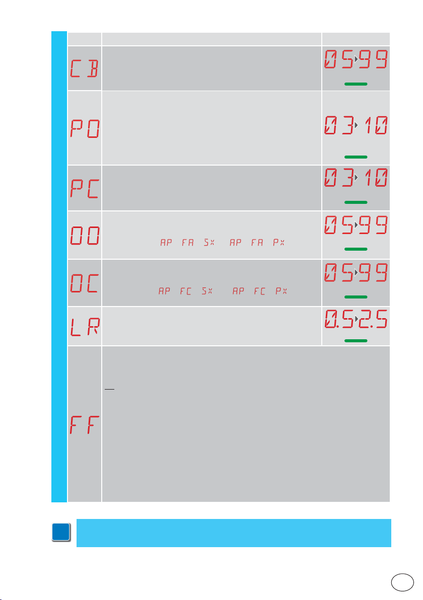
Display Description
OB - Adjustment of deceleration distance during closing. [cm]
Indicates the distance from the end of the closure stroke for the
start of the deceleration ramp.
05 - Minimum
99 - Maximum
PO - Adjustment of approach speed during opening [cm/s]
Indicates the speed from the end of the deceleration ramp to the
end of the opening stroke
03 - Minimum
10 - Maximum
NB: gradually increase the approach speed if there is a series of
quick vibrations (chattering) in heavy gates installed with a slight
incline.
PC - Adjustment of approach speed during closing [cm/s]
Indicates the speed from the end of the deceleration ramp to the
end of the closing stroke.
03 - Minimum
10 - Maximum
OO - Obstacle detection limit during opening [cm]
Indicates the distance from the opening stop at which disengagement is deactivated.
NB: not active if
→ → or if → → .
Selections
available
60
05
05
40
IP2288EN
BA
OC - Obstacle detection limit during closure [cm]
Indicates the distance from the closure stop at which reversal is
deactivated.
NB: not active if
LR - Electric lock release time [s]
If enabled, this indicates the electric lock activation time at the start
of every opening operation with the automation closed.
FF - Function of output +LP00 - courtesy light
01 - electric lock
02 - electr ic lock + release stroke
03 - ON-OFF flashing light
04 - ON-OFF flashing light for LED without oscillator
05 - fixed light (at 230 V AC, or LED with internal oscillator)
06 - proportional indicator light for open gate (with signal of battery operation)
07 - fixed indicator light for open gate (automation not closed)
08 - automation closed (for fail-safe electromagnets)
09 - automation open
10 - automation moving (can also be used for electromagnets that need to be powered
throughout the operation)
11 - automation opening
12 - automation closing
13 - maintenance alarm
14 - signal for batteries almost flat
ON - output always active
→ → and if → → .
NB: make adjustments gradually and only after performing at least three complete
operations to allow the control panel to be set correctly and detect any friction during
i
operations.
40
1.5
29
EN
Page 30
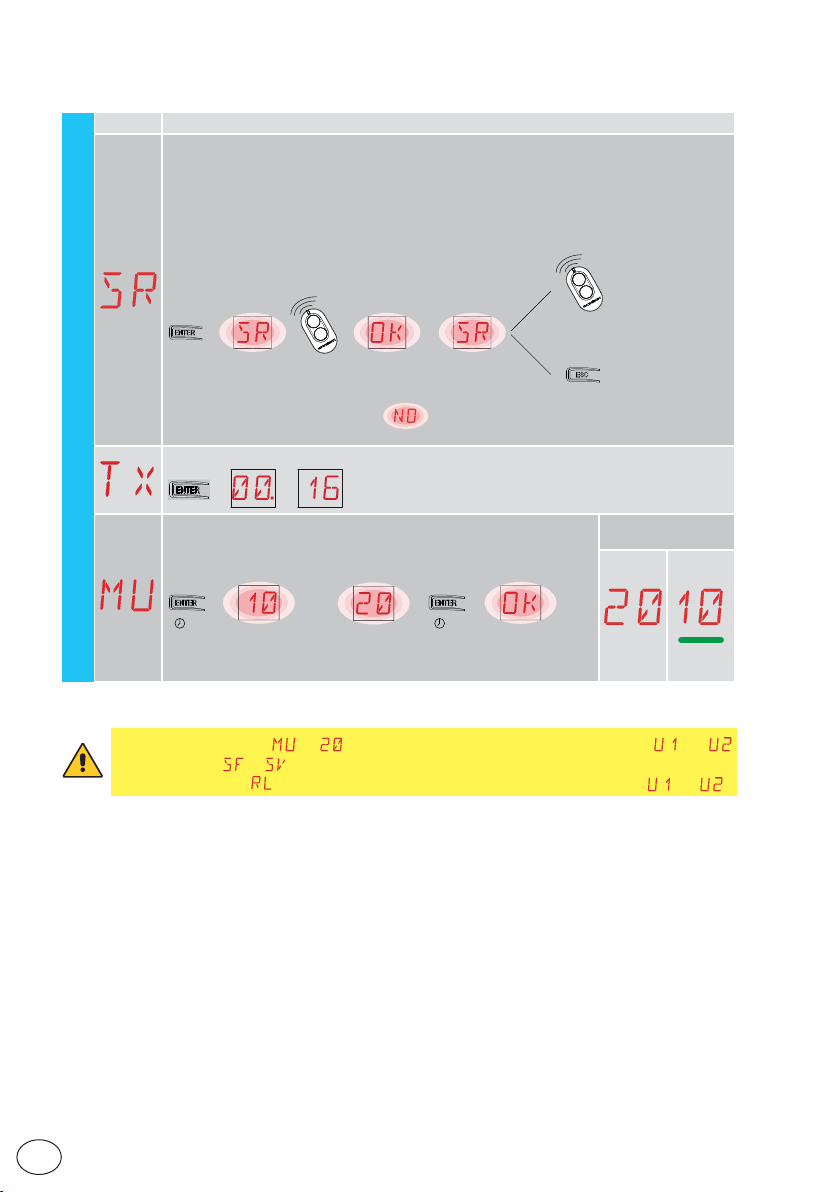
15.5 Second level menu - RO (Radio Operations)
Display Description
SR - Remote control storage
You can directly access the Remote control storage menu even with the display turned
off, but only with the Display visualisation mode option set to 00 or 03:
- for transmitting a remote control not present in the memor y;
- for transmitting an unstored channel of a remote control already present in the memory.
→
...x2, x3...
RO - Radio operations
→ →→
WARNING: if the display shows flashing, the remote control may already be
stored.
TX - Visualis ation of counter showing remote controls stored
→→ → 16 radiocomandi [esempio]
MU - Indication of maximum number of remote controls that can
be stored in the integrated memory
You can store a maximum of 100 or 200 remote control codes.
→→
→
oppure
16 remote controls (example)
or
→
Selections
available
→
2” 2”
20 - 200 remote controls that can be stored
10 - 100 remote controls that can be stored
WARNING: selecting → (200 remote controls), the configurations and
saved with the → command will be lost. This also applies for the last configuration reloaded with . In addition, new configurations cannot be saved on and .
EN
IP2288EN
30
Page 31
Display Description
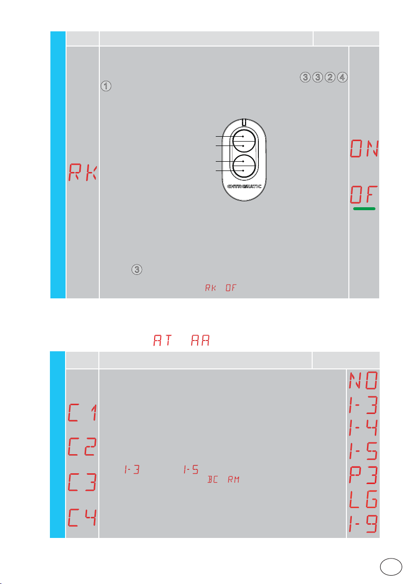
RK - Menu navigation using remote control keyboard
ON - Enabled
OF - Disabled
With the display turned off, quickly type in the sequence of keys
from the stored remote control you want to use.
1
Make sure all the CH keys are stored.
WARNING: dur ing navigation with a remote control keyboard ALL the stored
remote controls are inac tive.
Selections
available
3 3 2 4
1 (Enter)
2 (∆)
3 (Esc)
4
(∆)
→ .
RO - Radio operations
To make viewing and adjustment easier (avoiding the need to continuously
press the remote control), press the UP ↑ or DOWN ↓ key once to begin
slowly scrolling through the parameters.
This scrolling movement is faster if the UP ↑ or DOWN ↓ key is pressed twice.
To stop the scrolling, press ENTER.
To confirm your choice of parameter, press ENTER again.
To test any new setting, switch off the display and issue an opening command
using key
Navigation using a remote control keyboard is automatically disabled after 4
minutes of inactivity or by setting
.
3
15.5.1 Additional RO level parameters that can be configured
(available with → enabled)
Display Description
C1, C2, C3, C4 - Selection of CH1, CH2, CH3, CH4 function of stored remote
control.
NO - No set ting selected
1-3 - Opening command
1-4 - Closing command
1-5 - Step-by-step command
P3 - Partial opening command
LG - Command to switch the courtesy light on /off
RO
IP2288EN
1-9 - STOP command
If even just one (any) CH key of the remote control is stor ed, the opening or stepby-step command is implemented.
NB: the
tives, and depend on the selection
If 2-4 CH keys of a single remote control are stored, the functions matched in
the factory w ith the CH keys are as follows:
• CH1 = opening/step-by-step command
• CH2 = par tial opening command;
• CH3 =courtes y light on/of f command
• CH4 = STOP command.
(opening) and (step-by-step) options are available as alterna-
→ .
Selections
available
31
EN
Page 32
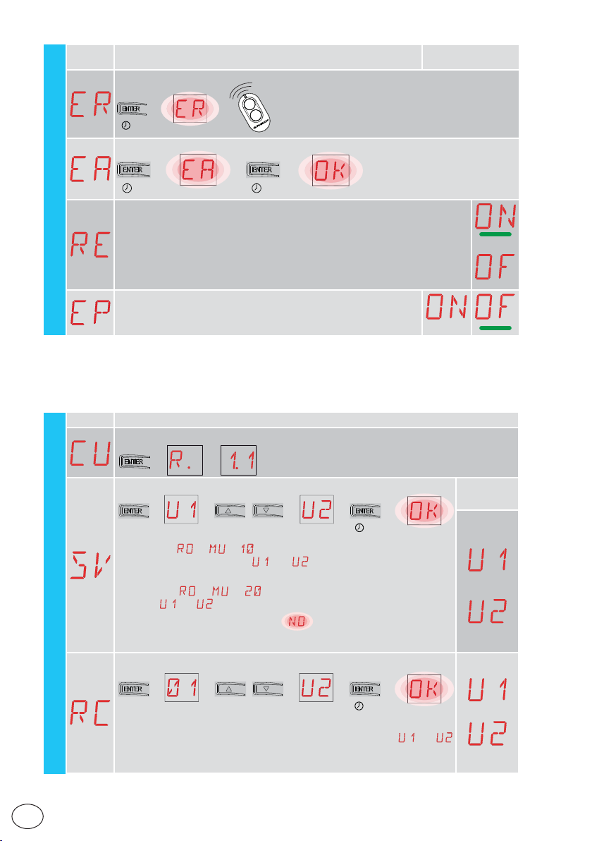
Display Description
ER - Deletion of a single remote control
→→
2”
EA - Total memory deletion
Selections
available
RO
→→
2” 2”
RE - Setting memory opening from remote control
OF - Disabled
ON - Enabled When enabled (ON), the remote programming is activated.
To store new remote controls without using the control panel, refer to the remote
control instructions.
NB: make sure you do not accidentally memorise unwanted remote controls.
EP -Set ting the coded area messages
If the po ssibilit y to receive coded messages is enabled, the control panel will be compatible with remote controls of the “ENCRYPTED” type.
→
15.6 Second level menu - SF (Special Functions)
Display Description
CU - Visualisation of the firmware version on the control panel
→→→ Release 1.1 [esempio]
SV - Saving user configur ation on control panel storage module.
→→ →→
[esempio]
(example)
By selecting → → you can save up to 2 personalised configurations in memory positions
present on the control panel.
WARNING: if → → is selected, no user configuration can be
saved on
WARNING: if the display visualises
may not be installed.
and .
and only with the storage module
(example)
→
2”
flashing, the memory module
Selections
available
EN
RC - Configuration loading
SF - Special Functions
→→ →→
[esempio]
(example)
It's possible to load the user configurations previously stored and
on the memory module of the control panel.
→
2”
IP2288EN
32
Page 33
Display Description
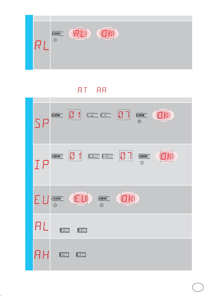
RL - Loading of last configuration set
→
→
2”
The control panel automatically saves the last configuration set, and keeps it memorised in
the storage module.
In the event of a fault or the replacement of the control panel, the last configuration of the automation can be restored by inserting the storage module and loading the last configuration set.
SF - Special Functions
15.6.1 Additional SF level parameters that can be configured
(available with → enabled)
Display Description
SP - Setting the password
→
2”
→
2”
SF
→→ →→
[esempio]
(example)
NB: this can only be selected when the password is not set.
Setting the password prevents unauthorised personnel from accessing selections and
adjustments.
You can delete the set password by selecting the sequence JR1=ON, JR1=OFF, JR1=ON.
IP - Inserting the password
→→ →→
(example)
[esempio]
NB: this can only be selected when the password is set.
When the password is not inserted, you can access the displ ay mode regardless of the
selection made with JR1.
When the password is inserted, you can access in maintenance mode.
EU - Deletion of user configurations and last configuration set in the stor age module
IP2288EN
→→
→
2” 2”
AL - Alarm counter
Used to view, in sequence, the counters of alarms that have been triggered at least once
(alarm code + number of times triggered).
With
recorded.
AH - Alarm log
Used to view, in sequence, alarms that have been triggered
(maximum 20).
With
The display shows the alarm number and code, alternated.
The highest number corresponds to the most recent alarm and the lowest number (0)
corresponds to the oldest alarm.
and , you can scroll through all the counters and see all the alarms
and , you can scroll through the entire alarm log.
33
EN
Page 34
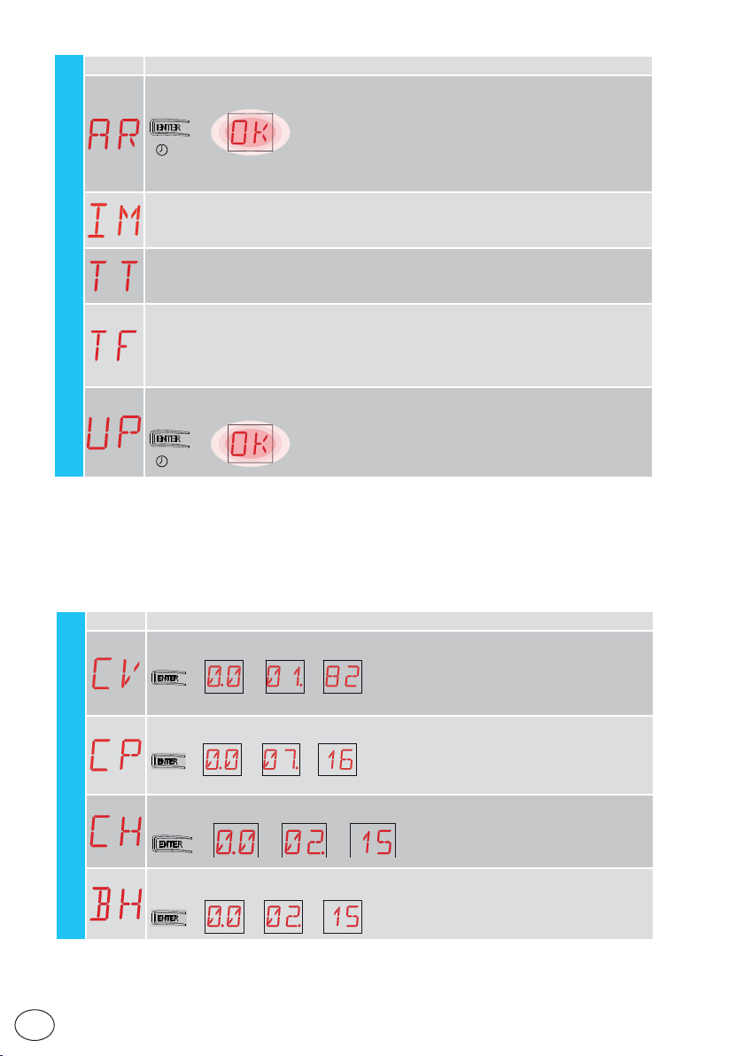
Display Description
p
AR - Alarm reset
Resets all the alarms in the memor y (counter s and log).
→
2”
NB: when the installation has been completed, you are advised to delete the alarms in
order to facilitate future checks.
IM - Motor current visualisation
TT - Display min / max temperatures recorded
SF
- by pressing for 2 seconds the values are reset
- minimum value with active right point
TF - Limit switch test
Only FA / FC are displayed when the respective limit switches are configured and active.
If the limit switches are active but not configured:
- FA = N.O. (both active points)
- FC = NO (no active point)
UP - Firmware update
Activates the card bootloader in order to update the firmware.
→
2”
15.7 Second level menu - CC (Cycles Counter)
Display Description
CV - Display of total operations counter
operations (example)
operations (example)
→
in batteria [esem
215 ore di funzionamento
215 operating hours via battery
→
in batteria [esempio]
(example)
EN
→→→ → 182 manovre [esempio]
CP - Display of partial operations counter
→→→ → 716 manovre [esempio]
CH - Display of power supply hour counter
→→→
CC - Cycle Counter
BH - Visualisation of counter for power supply hours via batter y
→→→
34
215 ore di funzionamento
215 hours of power supply
(example)
io]
IP2288EN
Page 35
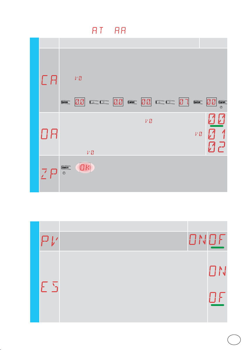
15.7.1 Additional CC level parameters that can be configured
(available with → enabled)
Display Description Selections
CA - Setting the maintenance alarm
(factory setting - alarm deactivated: 0.0 00. 00).
You can set the required number of operations (regarding the partial operations counter)
for signalling the maintenance alar m.
When the set number of operations is reached, the alarm message appears on the
CC
display
Example:
Setting the maintenance alarm after 700 operations (00) (07) (00)
OA - Selecting maintenance alarm display mode
00 - Visualisation on display (alarm message
01 - Visualisation on flashing light (with the automation idle, 4 fl ashes are
02 - Visualisation on "open gate" indicator light (with the automation closed,
ZP - Reset of partial operations counter
For correct functioning, you are advised to reset the par tial operations counter:
- after maintenance work;
- after setting the maintenance alarm interval.
.
→→→ →→
)
made and then repeated every hour) and on display (alarm message
4 flashes are made and then repeated every hour) and on display (alarm
message
→
2”
).
available
→→→→
).
2”
15.8 Second level menu - EM (Energy Management)
Display Description Selections
PV - Sol ar panel power supply (panels not supplied)
ON - Enabled
OF - Disabled
ES - Ene rgy-sav ing (disconn ection of accessor ies connec ted to termin als 0-1
when the automation is in standby)
ON - Enabled (the red point on the right of the display flashes every 5 s. Output
+LP- is managed only for courtesy light).
OF - Disabled
Power supply disconnec tion mode is activated after 15 s with the gate closed,
or when the gate is idle and automatic closure is not enabled.
The automation resumes its normal operation when a command is recei ved on
the radio board (6ZENRS-ZENPRS) or following a contact 30-5, 30-20.
WARNING: if you use accessories that need to remain powered even with
Energy Saving is enabled (e.g. L AN4 or GOPAV), set the jumper JR5 relating to
EM - Energy management
IP2288EN
the slot used on power supply 0-30.
35
available
EN
Page 36
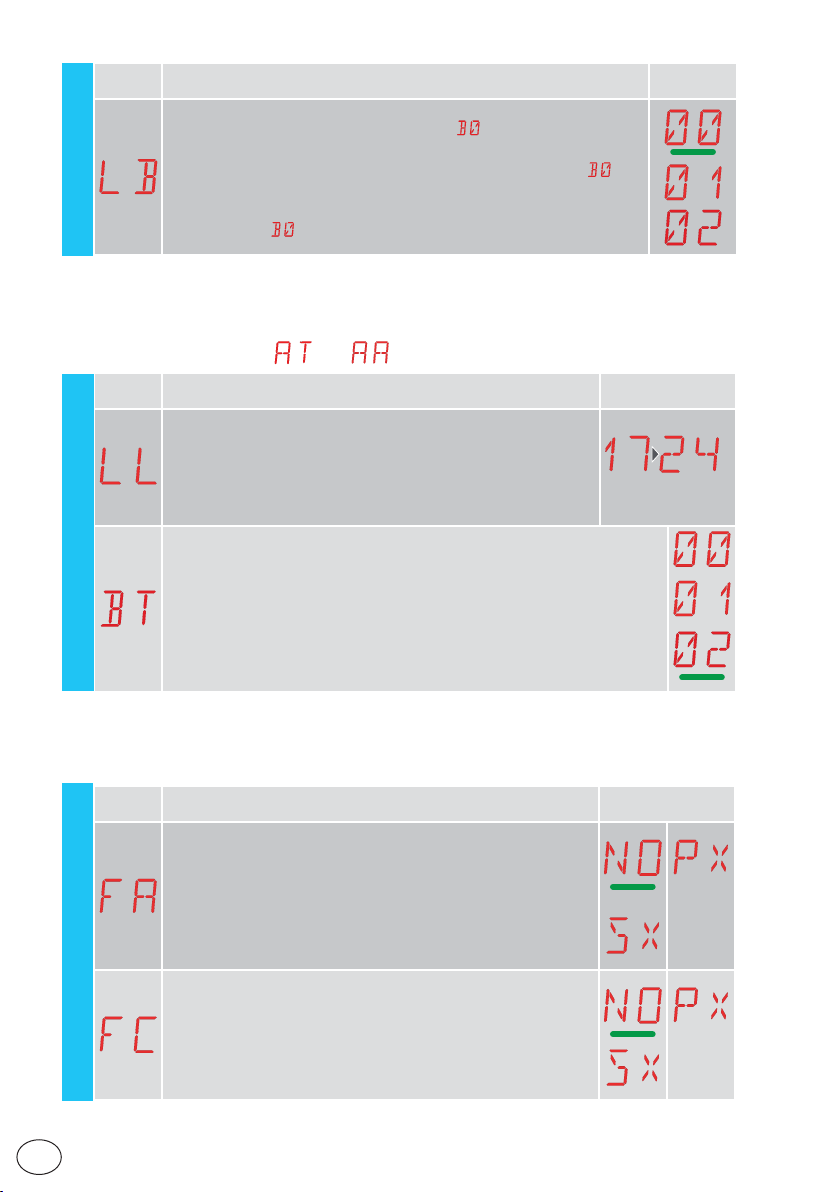
Display Description Selections
LB - Indication that batteries are almost flat
EM
00 - Visualisation on display (alarm message
01 - Visualisation on flashing light (with the automation idle, 2 flashes are
made and then repeated every hour) and on display (alarm message
02 - Visualisation on "open gate" indicator light (with the automation closed, 2
flashes are made and then repeated every hour) and on display
(alarm message
)
)
available
)
15.8.1 Additional EM level parameters that can be configured
(available with → enabled)
Display Description Selections
LL - Voltage threshold for indicating that batteries are almost
flat (V)
17 - Minimum
24 - Maximum
NB: it is set with an interval of sensitivity of 0.5 V shown when the
decimal point on the right lights up.
EM
BT - Battery mode
00 - Anti-panic (performs the opening operation follow ing a mains supply fail-
ure. The automation opens but does not accept any other commands until
the mains supply has been restored).
01 - Continuous operation - the last operation performed before control panel
switch-off will be an opening.
02 - Continuous operation - the last operation performed before control panel
switch-off will be an closure.
available
22
15.9 Second level menu - AP (Advanced Parameters)
Display Description Selections
FA - Selection of opening limit switch mode
NO - None
SX - Stop limit switch (after activation, the gate stops its movement)
PX - Proximity limit switch (after activation, the gate continues as far as
the end stop and any obstacle is considered a stop)
FC - Selection of closing limit switch mode
NO - None
SX - Stop limit switch (after activation, the gate stops its movement)
PX - Proximity limit switch (after activation, the gate continues as far as
the end stop and any obstacle is considered a stop)
AP - Advanced Parameters
36
EN
available
IP2288EN
Page 37
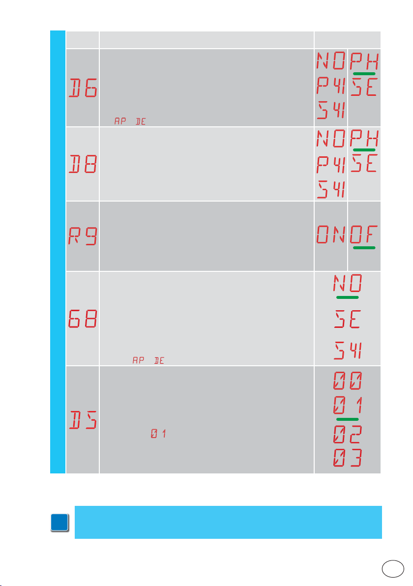
Display Description Selections
D6 - Selection of device connected to terminals 1-6
NO - None
PH - Photocells
P41 - Photocells with safety test
SE - Safety edge (if contact 1-6 opens, there is a disengagement of
10cm after the stop)
S41 - Safety edge with safety test (if contact 1-6 opens, after the stop
there is a disengagement of a duration depending on the selection
→ )
D8 - Selection of device connected to terminals 1-8
NO - None
PH - Photocells
P41 - Photocells with safety test
SE - Safety edge
S41 - Safety edge with safety test
R9 - Enabling automatic closing after command 1-9 (STOP).
ON - Enabled
OF - Disabled
When enabled (ON), after a command 1-9, the automation carries
out automatic closing (if enabled), after the set time
68 - Selection of the device simultaneously connected to terminals 1-6 and 1-8
NO - None
SE - Safety edge
S41 - Safety edge with safety test
AP - Advanced Parameters
If different from NO, the simultaneous opening of inputs 1-6 and 1-8
causes:
- movement stop and reversal during a closing operation
- movement stop and disengagement of a duration depending on the
selection
DS - Setting of display visualisation mode
00 - No visualisation
01 - Commands and safety devices with radio test
Display of countdown to automatic closure.
02 - Automation status
03 - Commands and safety devices
→ during an opening operation
.
available
IP2288EN
NB: the setting
received, for range checks.
allows you to see when a radio transmission is
NB: make adjustments gradually and only after performing at least three complete
operations to allow the control panel to be set correctly and detect any friction during
i
operations.
37
EN
Page 38
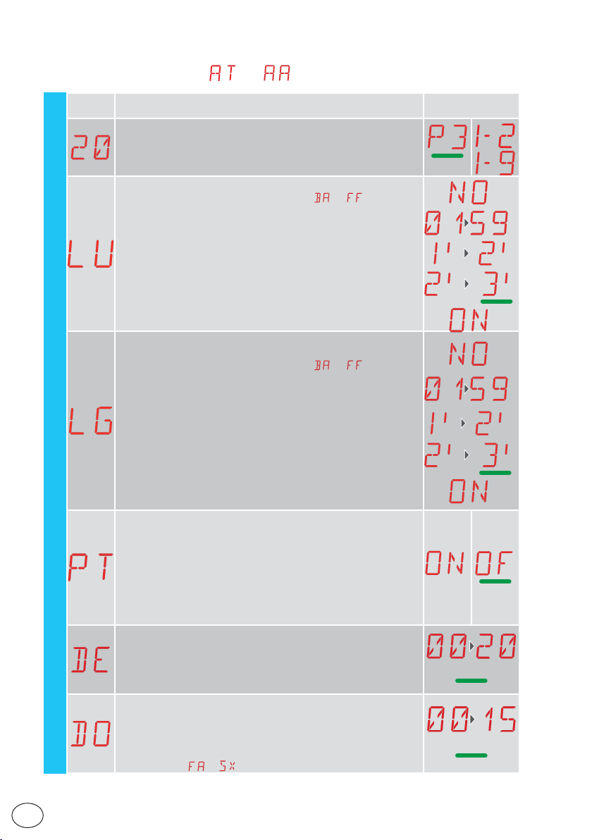
15.9.1 Additional AP level parameters that can be configured
(available with → enabled)
Display Description
20 - Partial opening command of terminal 1-20
P3 - Partial opening command
1-2 - Enabling of automatic closure
1-9 - Stop input
LU - Setting the courtesy light sw itch-on time (s)
To enable the parameter, set the selection
light".
It is set with dif ferent inter vals of sensitivity.
NO - Disabled
- from 01” to 59” with intervals of 1 second
- from 1’ to 2’ with interval s of 10 seconds
- from 2’ to 3’ with intervals of 1 minute
ON - Permanently enabled (switched off via remote control)
NB: the courtesy light switches on at the start of each operation.
LG - Switch-on time for independently commanded cour tesy light
[s]
To enable the parameter, set the selection
light".
It is set with dif ferent inter vals of sensitivity.
NO - Disabled
- from 01” to 59” with intervals of 1 second
- from 1’ to 2’ with interval s of 10 seconds
AP
- from 2’ to 3’ with intervals of 1 minute
ON - Switched on and off with remote control
NB: the switching on of the light does not depend on the start of an
operation, but can be commanded separately using the special remote
control key.
PT - Fixed partial opening
ON - Enabled
OF - Disabled
If ON, a partial opening command given on the partial opening position is ignored.
With contact 1-20 closed (for example with the timer or manual selecto r), the gate will partially open. If it is th en fully opened (command
1-3) and reclosed (even with automatic closure), it will stop at the
partial opening position.
DE - Disengagement setting if an edg e is triggered [cm]
Regulates the disengagement distance when an edge (active or passive) is triggered during opening or closure.
00 - Deactivated
20 - Maximum
DO - Setting of disengagement on stop during opening [mm]
Regulates the distance of the disengagement on the mechanical
opening stop.
00 - Disabled
15 - Maximum
NB: not active if
→
→ as "courtesy
→ as "courtesy
Selections
available
10
07
IP2288EN
EN
38
Page 39
IP2288EN
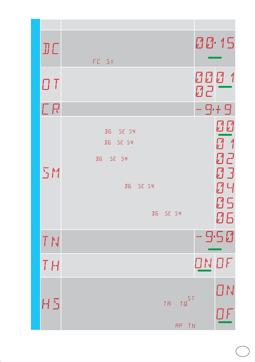
Display Description
DC - Setting of disengagement on stop during closure [mm]
Regulates the distance of the disengagement on the mechanical opening stop.
00 - Disabled
99 - Maximum
AP
NB: not active if
OT - Selection of type of obstacle identification
00 - Overcurrent or gate stopped
01 - Overcurrent
02 - Door stopped
NB: the obstacle identification for “door stopped” is faster but more
sensitive.
CR - Stroke estimate correction [%]
DO NOT USE (diagnostic purposes only)
SM - Selection of operating mode of device connected to terminals 1-6
00 - During the operation, the opening of the safety contact stops the movement
(with disengagement if
01 - During the operation, the opening of the safety contact stops the movement
(with disengagement if
tion is resumed.
02 - During the operation, opening of the safety contact stops the movement (with
disengagement if
operation is performed.
03 - During the closing operation, the opening of the safety contact reverses the
movement. During the opening operation, the safety device is ignored.
04 - During the opening operation, the opening of the safety contact stops the
movement (with disengagement if
the opening operation is resumed. During the closing operation, the safety device
is ignored.
05 - During the closing operation, the opening of the safety contact stops and reverses the movement. During the opening operation, the opening of the safety contact stops the movement (with disengagement if
06 - During a maneuver, the opening of the safety contact stops the movement.
When the contact closes again, automatic closing is disabled.
TN - Set ting of inter vention temperature for the NIO electronic antifreeze system and automatic HS ramps [°C]
This v alue does not refer to the ambient temperature, but to the internal control panel temperature.
TH - High temperature protection enable.
If ON, the automatic reclosing time is extended when the maximum
switchboard temperature is reached. If the condition per sists, all the
controls are disabled.
HS - Automatic ramp adjustment
ON - Enabled
OF - Disabled
When enabled (ON), at low ambient temperatures the start time
up to the maximum value and the acceleration time
the minimum value.
NB: for correct operation, the control panel must be exposed to the same ambient temperature as the motors.
The intervention temperature can be set with the selection
→
→ / ).
→ / ). When the contact closes again, the opera-
→ / ). When the contact closes again, an opening
Selections
available
→ / ). When the contact closes again,
→ / ).
and diminishes to
increases
→ .
07
20
39
EN
Page 40
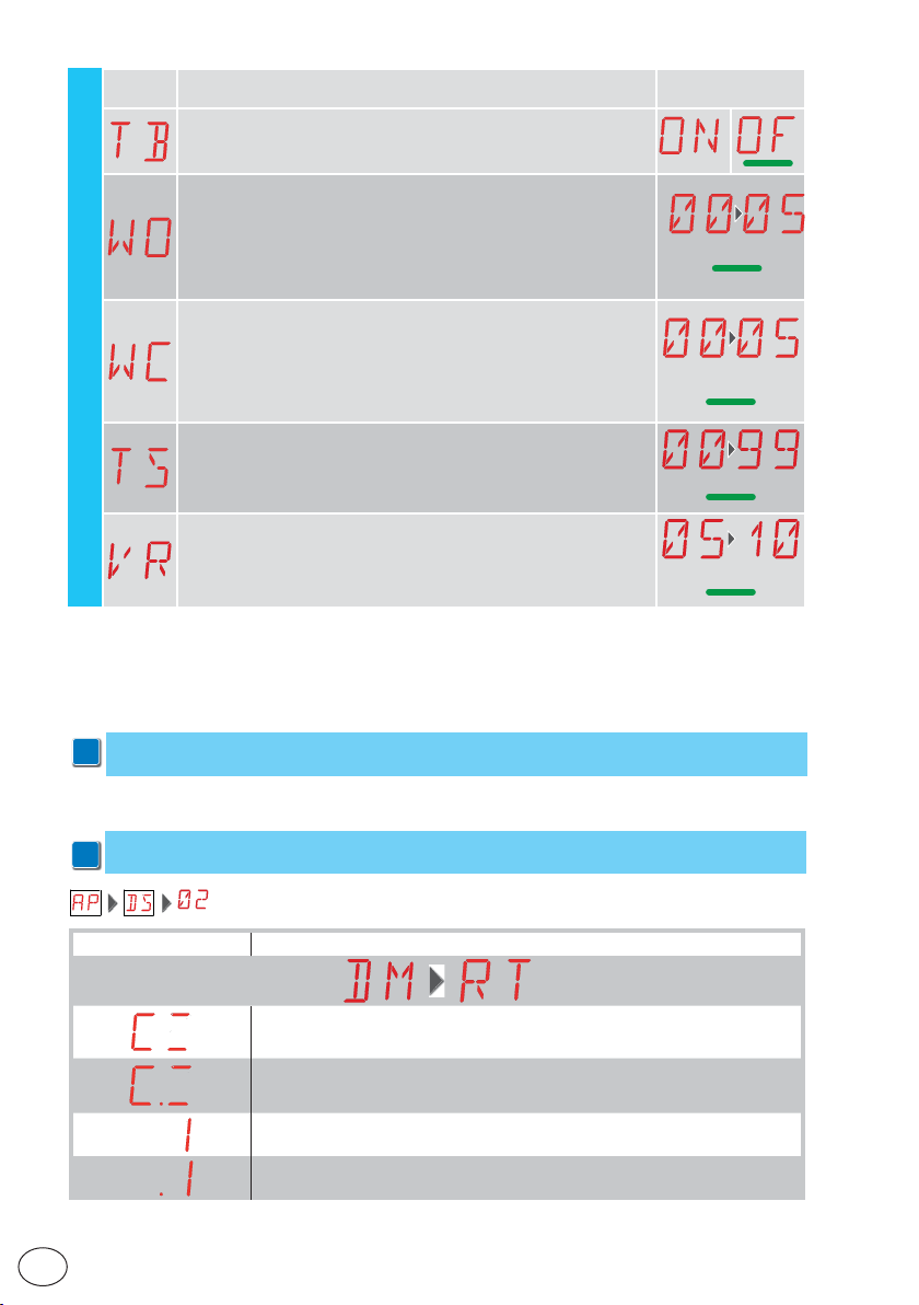
Display Description
TB - Permanent display of the internal control panel temperature
[°C]
WO - Setting of pre-flashing time on opening [s]
Adjustment of the lead time for the switch-on of the flashing light,
in relation to the start of the opening operation from a voluntary
command.
00 - Minimum
05 - Maximum
WC - Setting of pre-flashing time on closing [s]
AP
Adjustment of the lead time for the switch-on of the flashing light, in
relation to the start of the closing operation from a voluntar y command.
00 - Minimum
05 - Maximum
TS - Set ting of renewal of automatic closing time after PH safety
device release [%]
00 - Minimum
99 - Maximum
VR - Set ting of learning speed [cm/s]
16. Signals visualised on the display
Selections
available
00
00’’
99
8
NB: depending on the type of automation and control panel, certain visualisations may not
i
be available.
16.1 Display of automation status
NB: the automation status display mode is only visible with Display visualisation mode set
i
to 02.
Display Description
Automation closed
Automation closed Release door open
Automation open
Automation open Release door open
EN
IP2288EN
40
Page 41
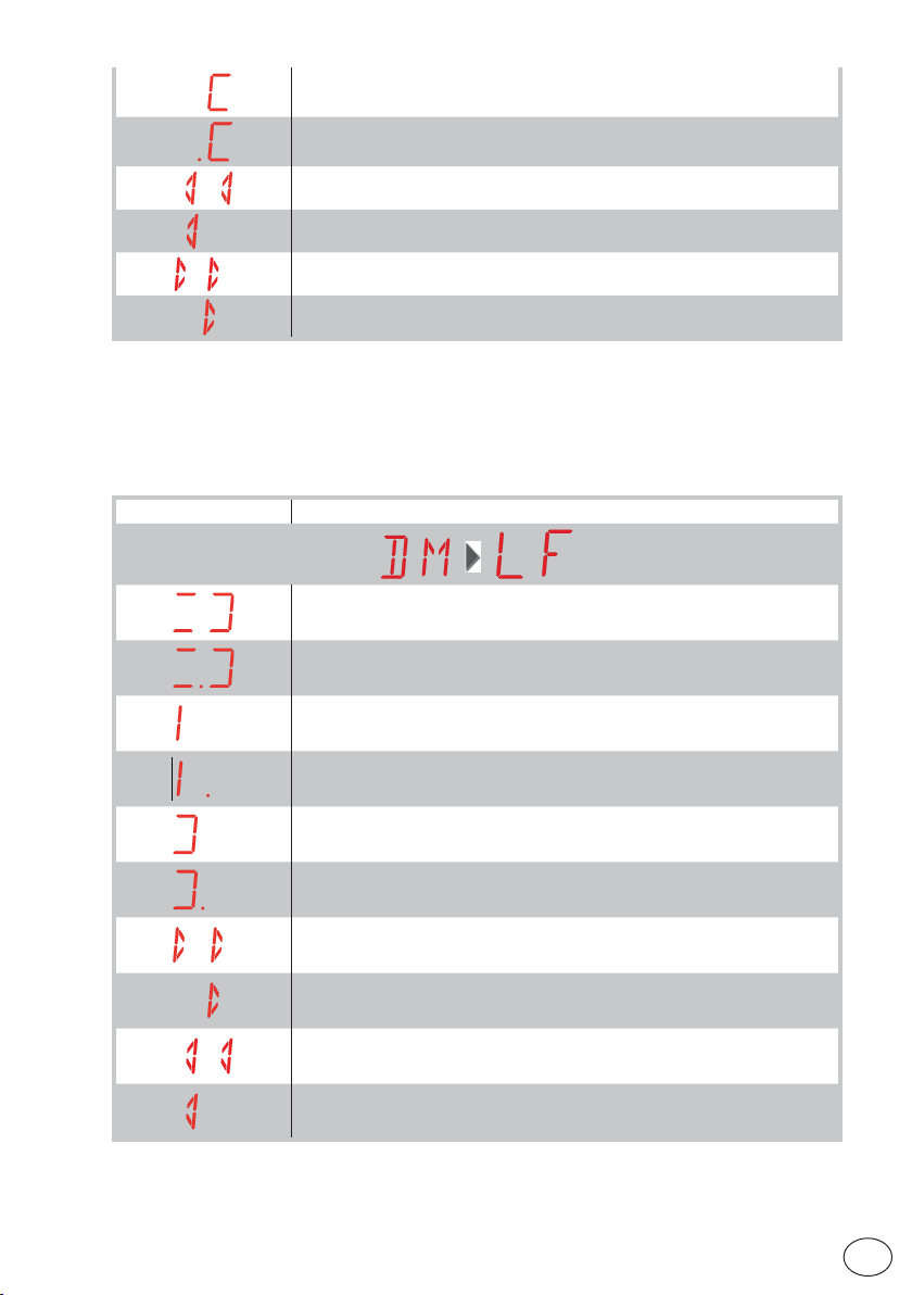
Automation stopped in intermediate position
Automation stopped in intermediate position Release door open
Automation closing
Automation that slows down during closing.
Automation opening
Automation that slows down during opening.
Display Description
Automation closed
Automation closed Release door open
Automation open
IP2288EN
Automation open Release door open
Automation stopped in intermediate position
Automation stopped in intermediate position Release door open
Automation closing
Automation that slows down during closing.
Automation opening
Automation that slows down during opening.
41
EN
Page 42
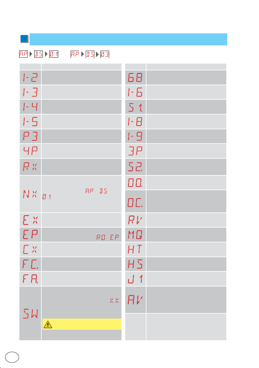
16.2 Display of safety devices and commands
NB: the safety device and command display mode is only visible with Display visualisation
i
mode set at 01 or 03.
Display Description Display Description
1-2 - Automatic closing activation command
1-3 - Opening command 1-6 - Safety device with opening and
1-4 - Closing command S1. - Detection of stop during closure
1-5 - Step-by-step command 1-8 - Safety with closing reversal
P3 - Partial opening command. 1-9 - STOP command
68 - Selection of the device simultaneously connected to terminals 1-6 and 1-8
closing stop
4P - Closing command with operator
present
RX - Radio reception (of any memorised key of a transmitter present in the
memory)
NX - Radio reception (of any non-memorised key)
NB: with the selection
, it is also visualised when a command is received from a non-stored
transmitter.
EX - Rolling-code radio reception out of
sequence
EP - Radio reception not complying with
the parameter configuration
CX - Command received from AUX1 board HT - Heating of the motors (NIO function)
FC. - Closure limit switch HS - Sharp NIO start-up
FA. - Opening limit switch JR1 - Variation of the JR1 jumper status
SW - Release door open.
When the release door is closed, the control panel performs a RESET (alarm ).
It is possible to ignore the reset by holding
down the ESC & DOWN keys for 3 seconds
until the SW stops flashing.
If the RESET is disabled, make sure
not to move the gate manually.
NB: If you return to the menu, the reset is
reactivated.
→ →
→
3P - Opening command with operator
present
S2. - Detection of stop during opening
OO.- Obstacle detection area reached
during opening
OC. Obstacle detection area reached
during closure
RV - Enabling/disabling of built-in radio
receiver via RDX
MQ - Learning operation of mechanical
end stops in progress
in progress
AV - Function anti-violation.
IP2288EN
EN
42
Page 43
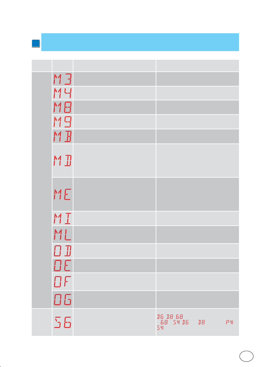
16.3 Visualisation of alarms and faults
WARNING: the visualisation of alarms and faults is possible with any visualisation selection.
i
The signalling of alarm messages takes priority over all other displays.
IP2288EN
Type of
alarm
Display Description Operation
Mechanical alarm
Power
supply
Settings
M3 - Automation blocked
M4 - Motor short circuit
M8 - Stroke too long
M8 - Stroke too short
MB - Absence of motor during an operation.
MD - Irregular operation of the opening
limit switch
If the limit switch is configured but can't be
found, each stop (from the OB deceleration
start point) is seen as an obstacle and indicated with MD.
ME - Irregular operation of the closure
limit switch
If the limit switch is configured but can't be
found, each stop (from the CB deceleration
start point) is seen as an obstacle and indicated with ME.
MI - Detection of fifth consecutive obstacle.
ML - Inverted limit switches
OD - Obstacle during opening
OE - Obstacle during closure
OF - Automation blocked on opening
OG - Automation blocked on closure
S6 - Incorrect setting of safety device test
Check the mechanical parts.
Check connection of motor.
Check the rack / chain belt
Manually check that the gate moves freely.
Check connection of motor.
Check connection of the opening limit
switch.
Check connection of the closure limit
switch.
Check for the presence of permanent obstacles along the stroke of the automation.
Check the positioning and connection of the
limit switches. Also check the motor connection.
Check for the presence of obstacles along
the automation stroke.
Check for the presence of obstacles along
the automation stroke.
Check the mechanical parts and make sure
there are no obstacles along the automation stroke.
Check the mechanical parts and make sure
there are no obstacles along the automation stroke.
Check the configuration of parameters
, , .
If
→ , and cannot be or
.
43
EN
Page 44
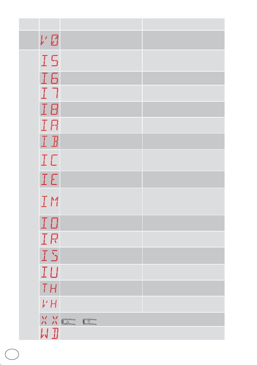
Type of
alarm
alarm
Service
Internal control panel alarm
Display Description Operation
V0 - Request for maintenance intervention
I5 - No voltage 0-1 (faulty voltage regulator
or short-circuit on accessories)
I6 - Excessive voltage 0-1 (faulty voltage
regulator)
I7 - Internal parameter error - value outside limits
I8 - Program sequence error
IA - Internal par ameter er ror (EEPROM/
FLASH)
IB - Internal parameter error (RA M)
IC - Oper ation time-out error (>5 min or
>7 min in learning mode)
IE - Power supply circuit fault
IM - MOSFET alarm - motor in short circuit or always ON
IO - Interrupted motor power circuit (motor MOSFET open or always OFF)
IR - Motor relay error
IS - Error on motor current read circuit test
IU - Error on motor voltage read circuit
test
TH - Intervention of high temperature
safety device
VH - Automation blocked due to high
temperature
XX - Firmware reset commanded by the simultaneous pressing of the
+ keys.
WD - Firmware reset not commanded
Proceed with the scheduled maintenance
intervention.
Check there is no short circuit in connection 0-1.
If the problem persists, replace the control
panel.
Replace the control panel.
Reset.
If the problem persists, replace the control panel.
Reset.
If the problem persists, replace the control panel.
Reset.
If the problem persists, replace the control panel.
Reset.
If the problem persists, replace the control panel.
Manually check that the gate moves freely.
If the problem persists, replace the control panel.
Reset.
If the problem persists, replace the control
panel.
Reset.
If the problem persists, replace the control panel.
Check the settings / operating of any limit
switches.
Reset.
If the problem persists, replace the control panel.
Reset.
If the problem persists, replace the control panel.
Reset.
If the problem persists, replace the control
panel.
Reset.
If the problem persists, replace the control
panel.
Do not carry out any operations.
If the problem persists, contact Technical
Service.
Do not carry out any operations.
If the problem persists, contact Technical
Service.
IP2288EN
EN
44
Page 45
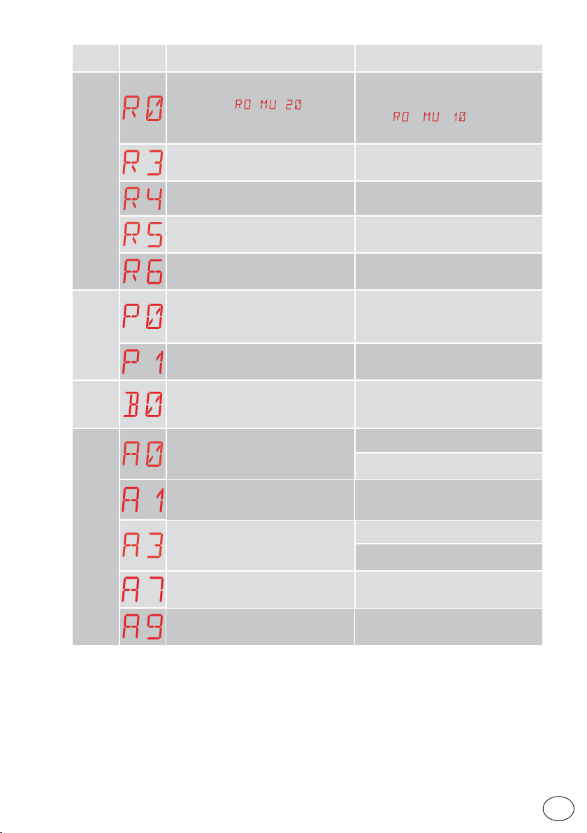
Type of
alarm
Display Description Operation
R0 - Insertion of a storage module containing over 100 stored remote controls
Warning: the
made automatically.
→ → setting is
To save the system configurations on the
storage module, delete any stored remote
controls and bring the total to less than
100. Set
→ → .
Radio operations alarm
alarm
Power supply
alarm
Battery
Accessories alarm
R3 - Storage module not detected
R4 - Storage module not compatible with
the control panel
R5 - No serial communication with the
storage module
R6 - Insertion of a specific storage module
for testing
P0 - No mains voltage
P1 - Microswitch voltage too low
B0 - Battery almost flat
A0 - Failure of test of safety sensor on contact 6
A1 - Simultaneous safety sensor test on
contacts 6 and 8 failed
A3 - Failure of test of safety sensor on contact 8
A7 - Incorrect connection of contact 9 to
terminal 41
A9 - Overload on output +LP-
Insert a storage module.
Insert a compatible storage module.
Replace the storage module.
Check the control panel is powered correctly.
Check the line fuse.
Check the mains power supply.
Check the control panel is powered correctly.
Check battery voltage.
Replace battery.
Check the device SOFA1-A2 is working correctly.
If the supplementary SOF board is not inserted, check the safety test is disabled.
Check the wiring and correct operation of
the safety sensor.
Check the device SOFA1-A2 is working correctly.
If the supplementary SOF board is not inserted, check the safety test is disabled.
Check that terminal 1 and 9 are correctly
connected.
Check the device connected to output +LP- is
working properly.
IP2288EN
45
EN
Page 46
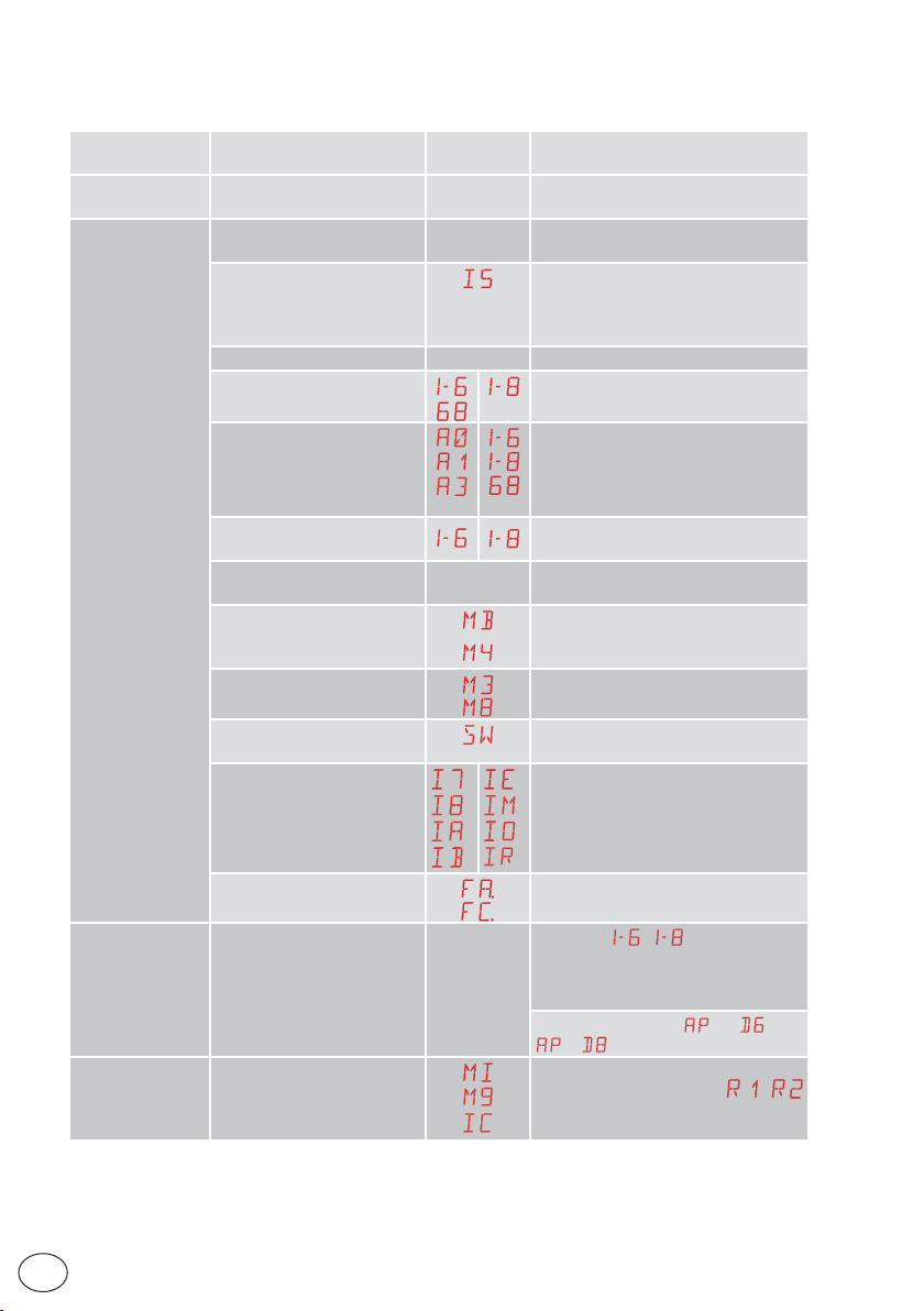
17. Troubleshooting
Problem Possible cause Alarm
The control panel
does not switch on
The automation
does not open or
close.
No power supply. Check the power supply cable and the
No power. Check power supply cable.
Short circuited accessories
Blown line fuse. Replace fuse.
Safety contacts are open.
Safety contacts not correctly
connected or self-controlled
safety edge not functioning
correctly.
Photocells activated.
The automatic closure does
not work.
Motor fault
Mechanical fault
Release microswitch open
Faulty control panel
signalling
relative wiring
Disconnect all accessories from terminals 0-1 (a voltage of 24V= must be present) and reconnect them one at a time.
Contact Technical Service
Check that the photocells are clean and
Check that the safety contacts are closed
correctly (NC).
Check connections to terminals 6-8 on
control panel and connections to the
self-controlled safety edge.
operating correctly.
Issue any command. If the problem per-
sists, contact Technical Service
Check motor connection, if the problem
persists, contact Technical Service.
Check the rack and transmission chain,
and/or the mechanical parts.
Check that the hatch is closed correctly
and the microswitch makes contact.
Contact Technical Service
Operation
The external safety
devices are not activated.
The automation
opens/closes
briefly and then
stops.
EN
Both limit switches are active.
Incorrect connections between the photocells and the
control panel.
There is a presence of friction.
46
Check the connection of the limit
switches.
Check that
Connect NC safety contacts together in
series and remove any jumpers on the
control panel terminal board.
Check the setting of
→ .
Manually check that the automation
moves freely and check the
adjustment
Contact Technical Service
/ is displayed
→ and
/
IP2288EN
Page 47
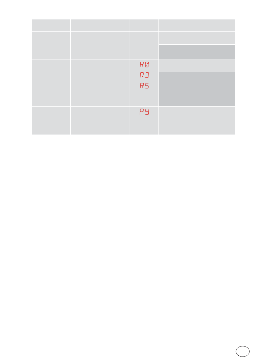
Problem Possible cause Alarm
The remote control
has limited range
and does not work
with the automation moving.
The remote control
does not work
The flashing light
is not working
The radio transmission is impeded by metal structures and
reinforced concrete walls.
No storage module or incorrect storage module.
The wires of the flashing light
are detached or have short
circuited.
signalling
Operation
Install the antenna outside.
Replace the transmitter batteries.
Switch the automation off and plug in the
correct storage module.
Check the correct memorisation of the
transmitters on the built-in radio. If there
is a fault with the radio receiver that is
built into the control panel, the remote
control codes can be read by removing
the storage module.
Check the connections.
If the problem persists, contact Technical Service.
IP2288EN
47
EN
Page 48
All the rights concerning this material are the exclusive property of Entrematic Group AB.
Although the contents of this publication have been drawn up with the greatest care, Entrematic Group AB
cannot be held responsible in any way for any damage caused by mistakes or omissions in this publication.
We reserve the right to make changes without prior notice.
Copying, scanning and changing in any way are expressly forbidden unless authorised in writing by Entrematic
Group AB.
IP2288EN
Entrematic Group AB
Lodjursgatan 10
SE-261 44, Landskrona
Sweden
www.entrematic.com
 Loading...