

Page 1
Ditec SPRINTSET
Istruzione modulo customizzato
Customization module instruction
IP2184 • 2015-11-25
www.ditecentrematic.com
Page 2
Avvertenze generali per la sicurezza
SPRINTSET
Il presente manuale di installazione è rivolto esclusivamente a personale qualificato.
Leggere attentamente le istruzioni prima di iniziare l’installazione del prodotto. I materiali dell’imballaggio (plastica, polistirolo, ecc.) non vanno
dispersi nell’ambiente e non devono essere lasciati alla portata dei bambini in quanto potenziali fonti di pericolo.
Prima di iniziare l’installazione verificare l’integrità del prodotto.
ITALIANO
Per l’eventuale riparazione o sostituzione dei prodotti dovranno essere utilizzati esclusivamente ricambi originali.
La manipolazione delle parti elettroniche deve essere effettuata munendosi di bracciali conduttivi antistatici collegati a terra.
Installazione
• Togliere alimentazione (rete e batterie).
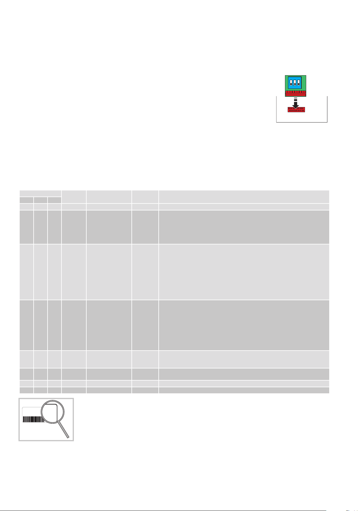
• Inserire il modulo SPRINT SET sul connettore COM presente sul quadro elettronico EL38.
• Collegare alimentazione (rete e batterie).
1
23
ON
OFF
Descrizione e funzionamento
Il modulo SPRINT SET consente di abilitare e disabilitare alcune configurazioni predefinite per l’utilizzo dell’automazione
Ditec SPRINT.
Per abilitare le configurazioni, procedere come indicato. Se la configurazione non è andata a buon fine il LED IN, sul quadro
elettronico, lampeggia.
1. Premere il pulsante OPEN sul quadro elettronico per 4 s. Il LED IN lampeggia.
2. Configurare i DIP della SPRINT SET come desiderato, entro 5 minuti.
3. Premere il pulsante OPEN sul quadro elettronico per 2 s per completare la procedura. Il LED IN interrompe il lampeggio.
Le configurazioni sono di due tipi: “G1” o “Generico”.
1. Le configurazione di tipo “G1” riguardano l’utilizzo dell’uscita G1 sul quadro elettronico. Le configurazioni di questa categoria sono esclusive, e solo
una di queste configurazioni può essere attiva. L’abilitazione di una configurazione causa l’annullamento di quella precedentemente impostata.
2. Le configurazioni di tipo “Generico” possono essere abilitate indipendentemente o in aggiunta alle altre configurazioni attivate.
3. Se viene abilitata la configurazione “0”, tutte le impostazioni attive vengono disabilitate.
COM
EL38
DIP
1 2 3
OFF OFF
OFF
ON OFF OFF 1 Apertura disabilitata
ON OFF 2 Sicurezza di presenza
OFF
ON ON OFF 3 Chiudi porta G1 - Quando la porta è aperta manualmente per più di 3°, la forza in chiusura si disabilita e la
OFF OFF ON 4 Segnale di allarme G1 L’uscita G1è abilitata come uscita allarme, si attiva quando viene rilevata una condizione di
ON OFF ON 5 Spinta in chiusura
OFF ON ON 6 NON USARE GENERICO
ON ON ON 7 NON USARE GENERICO
N.
CONFIG.
0 Standard / Reset
CONFIGURAZIONE TIPO DESCRIZIONE FUNZIONAMENTO
durante la chiusura
in apertura
disabilitata
Vedi funzionamento come da istruzione SPRINT IP2185.
G1 Il DIP6 non è attivo.
N.B.: il sensore di sicurezza in chiusura non è testabile e va collegato ai contatti 1-8.
L’uscita G1 ha tensione positiva e si spegne durante la chiusura.
Usare l’uscita G1 per il contatto del sensore di apertura sul lato di apertura al fine di disabilitare il sensore stesso durante la chiusura, evitando così riaperture indesiderate della
porta.
G1 Il contatto 9 diventa una sicurezza in apertura.
Collegare il sensore di sicurezza “APRE” a G1-9.
L’apertura del contatto di sicurezza arresta la manovra di apertura.
Se il contatto si richiude entro 4 sec. , la porta riprende la manovra di apertura e, una volta
aperta, si richiude dopo il tempo di chiusura automatica.
Se il contatto resta chiuso per un tempo maggiore di 4 sec. , l’anta chiude dopo il tempo di
chiusura automatica.
- Il DIP 6 non è attivo.
- L’uscita G1 si comporta come un’uscita test, verificando il sensore di sicurezza di apertura
e/o chiusura.
porta rimane nella posizione in cui viene lasciata.
Quando la porta è ferma, il tempo di chiusura automatica inizia il conteggio per permettere
la chiusura automatica.
Se la porta viene movimentata nuovamente, il tempo di chiusura automatica ri-inizia il
conteggio.
- Il DIP6 non è attivo e la funzione Push and Go è sempre disabilitata.
- L’uscita G1 si comporta come un’uscita test 41, verificando il sensore di sicurezza in apertura e/o chiusura.
allarme o di porta bloccata, impedendo il normale funzionamento della porta.
N.B.: il sensore di sicurezza in chiusura non è testabile e va collegato ai contatti 1-8.
GENERICO La spinta di mantenimento a porta chiusa viene disabilitata.
N.B.: utilizzo non consigliato per porte soggette a spinta del vento.
EL38
1511123456
Tutti i diritti relativi a questo materiale sono di proprietà esclusiva di Entrematic Group AB.
Sebbene i contenuti di questa pubblicazione siano stati redatti con la massima cur a, Entrematic Group AB non può assumersi alcuna responsabilità per danni
causati da eventuali er rori o omissioni in questa pubblicazione. Ci riserviamo il diritto di apportare eventuali modifiche senza preavviso.
Copie, scansioni, ritocchi o modifiche sono espressamente vietate senza un preventivo consenso scritto di Entrematic Group AB.
13
Tutte le funzionalità descritte sono presenti a partire dalla versione num. 13 (fare riferimento alle ultime 2 cifre del
numero di serie presente nell’etichetta prodotto del quadro elettrico).
2
IP2184 - 2015-11-25
Page 3
General safety precautions
SPRINTSET
This installation manual is intended for professionaly competent personnel only.
Read the instructions carefully before beginning to install the product. Packaging materials (plastics, polystyrene, etc) must not be allowed to litter
the environment and must be kept out of the reach of children for whom they may be a source of danger. Before beginning the installation check
that the product is in perfect condition.
For repairs or replacements of products only original spare parts must be used.
The electronic parts must be handled using earthed antistatic conductive arms.
Installation
• Disconnect the power supply (mains and batteries).
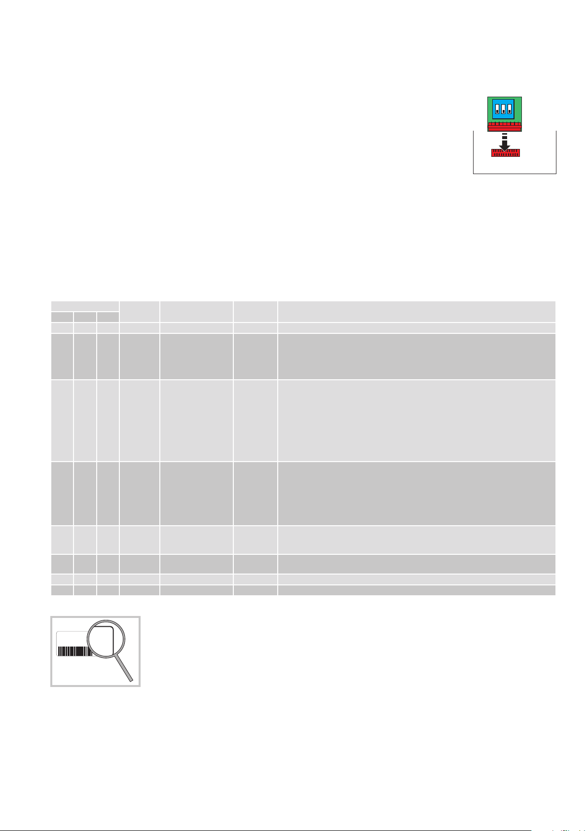
• Place the SPRINT SET module on the COM connector on the EL38 control panel.
• Connect the power supply (mains and batteries).
Description and operation
The SPRINT SET module can be used to enable and disable a number of configurations preset for use of the Ditec SPRINT automation.
To enable the configurations, do the following. If the configuration has not been enabled, the IN LED on the control panel flashes.
Press the OPEN button on the control panel for 4 s. The IN LED flashes.
Configure the SPRINT SET DIPs as desired within 5 minutes.
Press the OPEN button on the control panel for 2 s to complete the procedure. The IN LED stops flashing.
There are two types of configuration: “G1” or “Generic”.
1. “G1” configurations concern the use of the output G1 on the control panel. The configurations in this category are exclusive and only one of these
configurations can be activated. When a configuration is enabled, the previously set one is cancelled.
2. “Generic” configurations can be enabled regardless or together with the other activated configurations.
3. If configuration “0” is enabled, all the active settings are disabled.
1
23
COM
ON
OFF
EL38
ENGLISH
DIP
1 2 3
OFF OFF OFF 0 Standard / Reset See operation as indicated in the SPRINT IP2185 instructions.
ON OFF OFF 1 Opening disabled
OFF ON OFF 2 Presence sensing
ON ON OFF 3 Door closer G1 - - When the door is opened manually by more than 3°, the closure force is disabled and the
OFF OFF ON 4 Alarm signal G1 Output G1 is enabled in the same way as an alarm output, it is activated when an alarm or
ON OFF ON 5 Closure thrust
OFF ON ON 6 DO NOT USE GENERIC
ON ON ON 7 DO NOT USE GENERIC
CONFIG.
NO.
CONFIGURATION TYPE DESCRIPTION OPERATION
while closing
safety device during
opening
disabled
G1 DIP6 is not activated.
NB: the closure safety sensor cannot be tested. It must be connected to contacts 1-8.
Output G1 has positive voltage and switches off while closing.
Use output G1 for the opening sensor contact on the opening side in order to disable the
sensor while closing and prevent undesired reopening of the door.
G1 Contact 9 becomes an opening safety device.
Connect the “OPEN” safety sensor to G1-9.
Opening the safety contact stops the opening operation.
If the contact closes again within 4 sec., the door resumes its opening operation and, once
open, recloses after the automatic closure time.
If the contact remains closed for more than 4 sec., the door wing closes after the automatic
closure time.
- DIP 6 is not active.
- Output G1 behaves like a test output, checking the opening/closure safety sensor.
door stays in the position it was left in.
When the door is still, the automatic closing time starts and enables automatic closing.
If the door is opened again, the automatic closing time restarts.
- DIP6 is not activated and the Push and Go function is always disabled.
- Output G1 behaves in the same way as test output 41 by checking the safety sensor during
opening amd closing.
blocked door condition is detected and prevents normal operation of the door.
NB: the closure safety sensor cannot be tested. It must be connected to contacts 1-8.
GENERIC The closed door hold thrust is disabled.
NB: this type of use is not recommended for doors subject to the effect of the wind.
All the rights concerning this material are the exclusive property of Entrematic Group AB.
Although the contents of this publication have been drawn up with the greatest care, Entrematic Group A B cannot be held re sponsible in any w ay for any damage
caused by mistakes or omissions. We reserve the right to make changes without prior notice.
Copying, scanning and changing in any way are expressly forbidden unless authorised in writing by Entrematic Group AB.
IP2184 - 2015-11-25
EL38
1511123456
13
All the functions described here are available from version no.13 (refer to the last 2 figures of the serial number on
the label on the control panel).
3
Page 4
IP2184 - 2015-11-25
Entrematic Group AB
Lodjursgatan 10
SE-261 44, Landskrona
Sweden
www.ditecentrematic.com
 Loading...