

Page 1
Ditec MD1-MD2
Installation manual for display module for diagnostics and advanced controls.
IP1938EN
MD1
MD2
VALOR
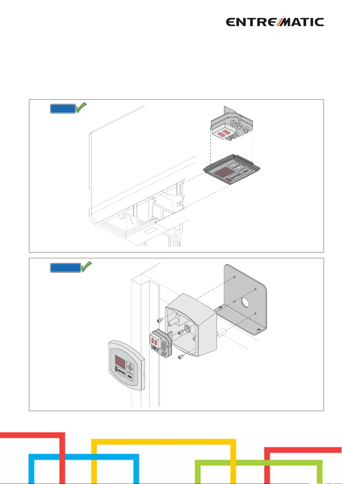
Fig. 1
QIK80EH
www.entrematic.com
Fig. 2
Page 2

2
IP1938EN - 2017-12-07
Page 3
Index
Subject Page
1. General safety precautions 4
2. Technical data 4
3. Installation 4
4. Electrical connections 5
4.1 Use method selection 5
5. Commands 6
5.1 Switching on and off 6
5.2 Key combinations 6
6. Menu 7
6.1 Main menu 7
6.2 Second level menu - BC (Basic Configurations) 8
6.3 Second level menu - BA (Basic Adjustments) 9
6.4 Second level menu - RO (Radio Operations) 12
6.5 Second level menu - SF (Special Functions) 15
6.6 Second level menu - CC (Cycles Counter) 17
6.7 Second level menu - EM (Energy Management) 18
6.8 Second level menu - AP (Advanced Parameters) 19
7. Display viewing mode 22
7.1 Viewing of Selector settings 22
7.2 Viewing of Automation status 22
7.3 Viewing of Commands and safeties 23
7.4 Viewing of alarms and faults 26
Caption
This symbol indicates instructions or notes regarding safety issues which require particular attention.
This symbol indicates informations which are useful for correct product function.
i
This symbol indicates instructions or notes intended for technical and expert personnel.
STOP
This symbol indicates operations not to be effected for not compromise the correct operation of the automation.
This symbol indicates options and parameters which are only available with the indicated item.
This symbol indicates options and parameters which are not available with the indicated item.
IP1938EN - 2017-12-07
3
Page 4
1. General safety precautions
This installation manual is intended for qualified personnel only.
Installation, electrical connections and adjustments must be performed in accordance with Good Working Methods and in
compliance with applicable regulations.
Before installing the product, carefully read the instructions. Bad installation could be hazardous.
The packaging materials (plastic, polystyrene, etc.) should not be discarded in the environment or left within reach of chil-
dren, as these are a potential source of hazard.
Before installing the product, make sure it is in perfect condition.
The protective casing of the automation must be removed by qualified personnel only.
For repairs or replacements of products only original spare parts must be used. The installer shall provide all information relating
to automatic, manual and emergency operation of the motorized door, and provide the user with operating instructions.
2. Technical data
MD1 MD2
Temperature -20 °C - +55 °C -20 °C - +55 °C
Degree of protection IP20 IP33
3. Installation
(Fig. 1) On VALOR automations, fix the MD1 display module as prearranged on the automation head, or (alternatively) using the
MDA support near the automation itself.
(Fig. 2) On QIK80EH automations, fix the MD2 display module as prearranged inside the barrier cabinet using the bracket supplied,
or (alternatively) near the automation itself.
4
IP1938EN - 2017-12-07
Page 5
4. Electrical connections
BIXMR2
CONTROL
PANEL
0 12122
Green
Yellow
Brown
White
max 50 m (shielded cable)
0 12122
J1
J2
RDX
ENTER
GOLR
ANT
UP
DOWN
ESC
PPC2
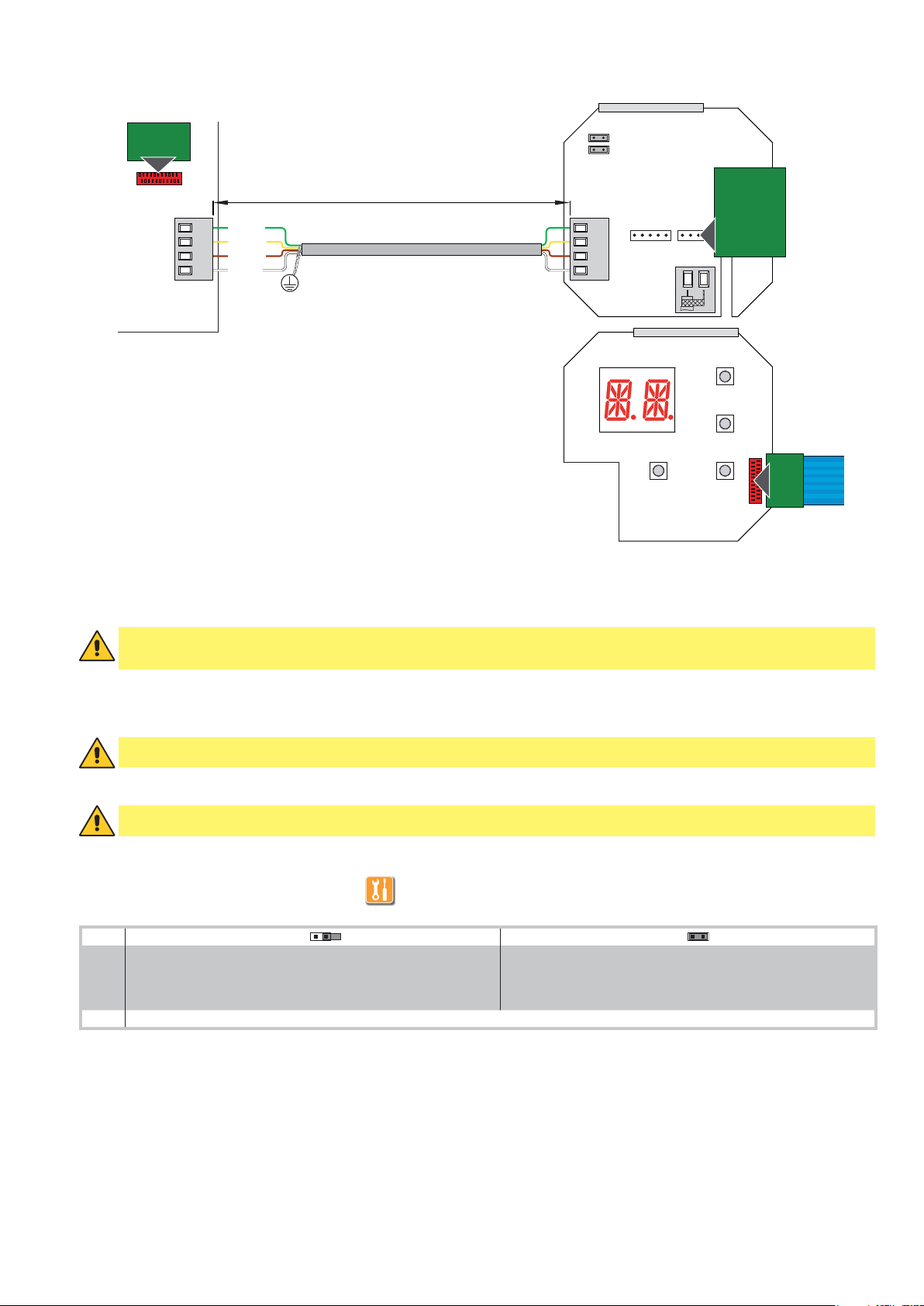
Make the electrical connections as shown in the figure.
WARNING: after having connected the display module to the control panel, turn on the power and wait 30 s for autoconfiguration of the display module and recognition of the automation.
The MD1-MD2 display module has a housing for a plug-in card, such as GOLR radio receiver. If present, the GOLR radio receiver
must be installed on the MD1-MD2 display module.
WARNING: the plug-in cards must be inserted and removed with the power supply disconnected.
WARNING: do not connect storage modules BIXMR2 or BIXMR.
4.1 Use method selection
OFF ON
J1 Visualization mode. It is only possible to visualize the values and
parameters present.
J2 FUTURE USE
Maintenance mode. It is possible to visualise and modif y the values
and parameters present.
The entr y in maintenance mode is indicated by the permanent
switching on of the right-hand point.
IP1938EN - 2017-12-07
5
Page 6
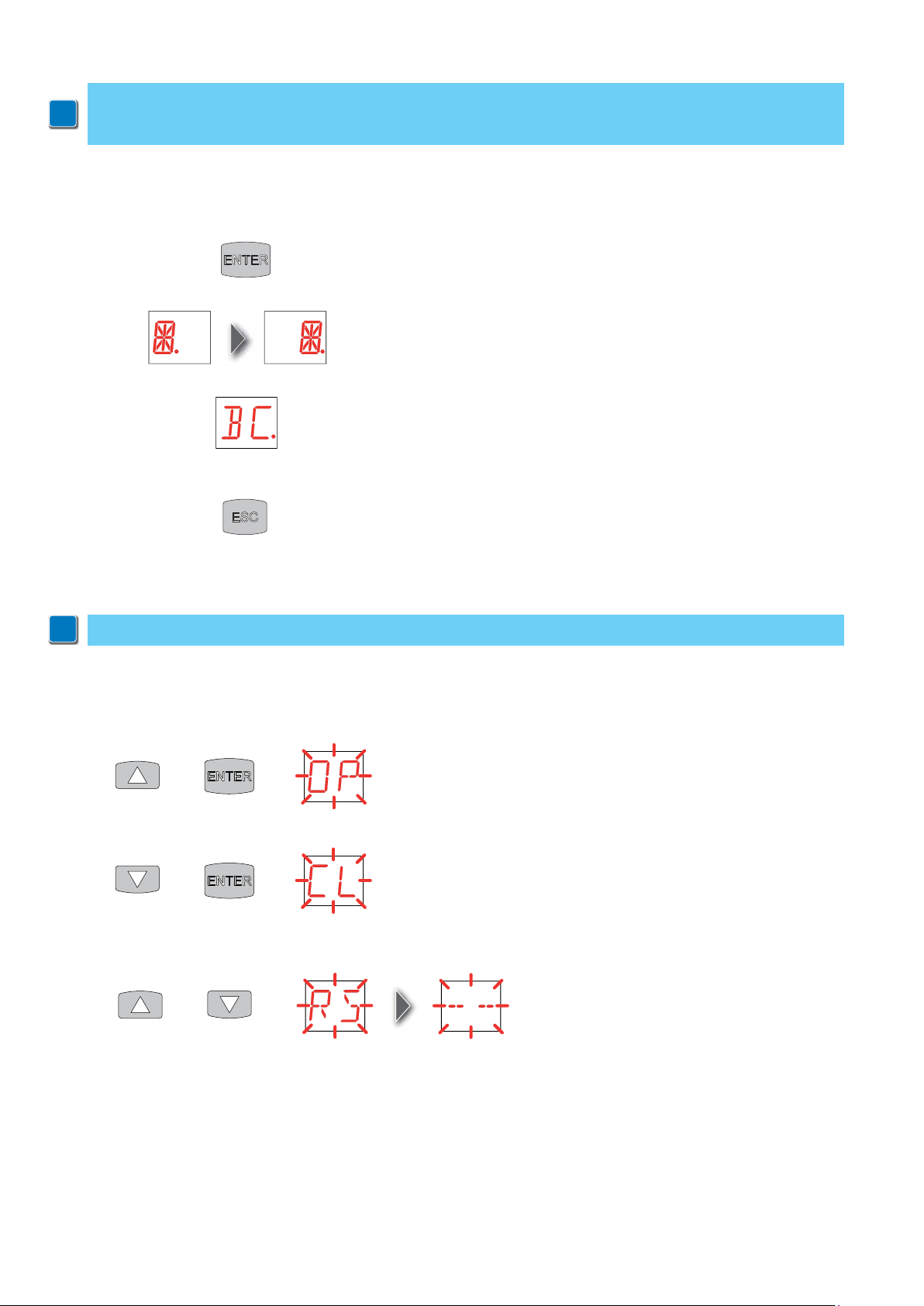
5. Commands
NOTE: the pressure on the keys can be quick (less than 2 s) or prolonged (longer than 2 s). Unless specified otherwise,
quick pressure is intended.
i
To confirm the setting of a parameter, prolonged pressure is necessary.
5.1 Switching on and off
The procedure to switch on the display is as follows:
- press the ENTER key
- start of display functioning check
- visualization of first level menu
The procedure to switch off the display is as follows:
- press the ESC key and keep it pressed
NOTE: the display switches off automatically after 60 s of inactivity.
i
5.2 Key combinations
The simultaneous pressing of the keys and ENTER performs an opening command.
The simultaneous pressing of the keys and ENTER performs a closing command.
The simultaneous pressing of the keys and performs a POWER RESET command.
(Interruption of the power supply and restart of the automation).
+=
+=
+=
6
IP1938EN - 2017-12-07
Page 7
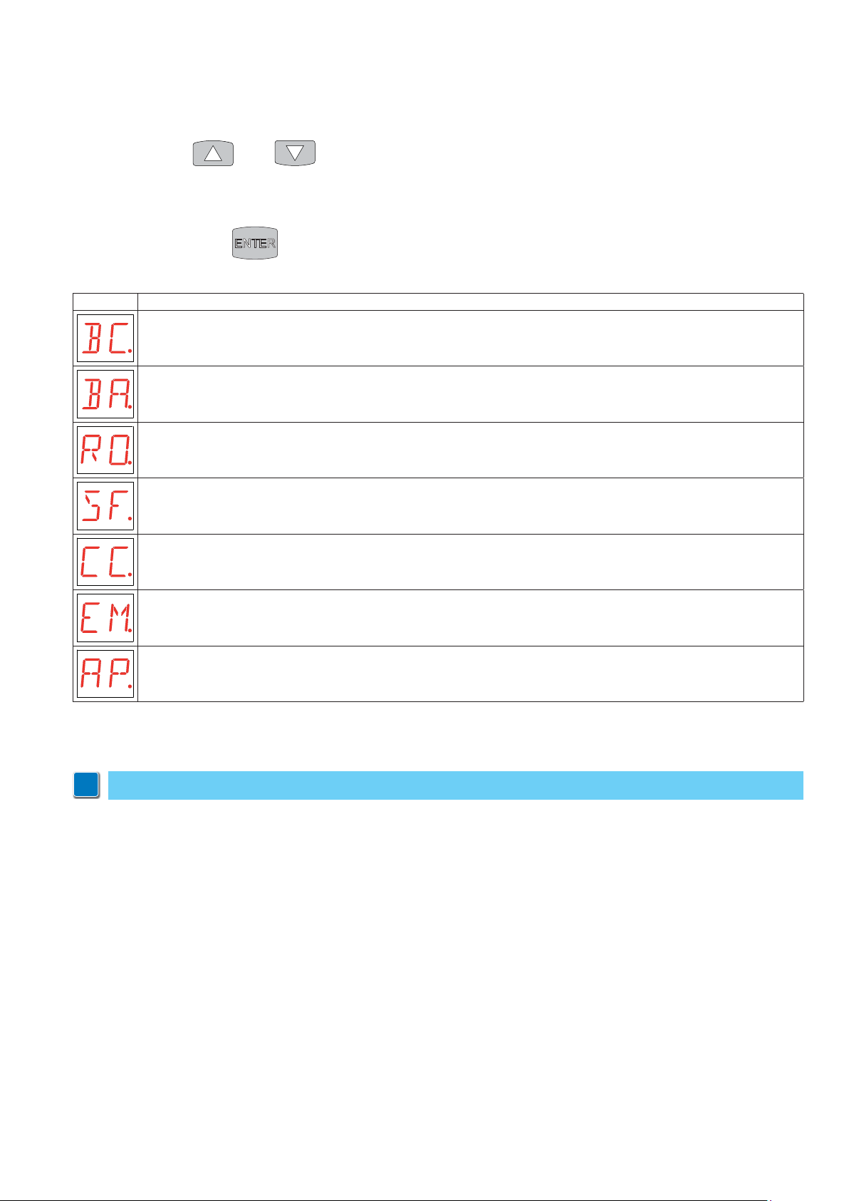
6. Menu
6.1 Main menu
- use the keysŸandź to select the required function
- press the ENTER key to confirm
Display Description
BC - Basic Configurations.
The menu allows to visualize and modify the main settings of the control panel.
BA - Basic Adjustments.
The menu allows to visualize and modify the main adjustments of the control panel.
RO - Radio Operations.
The menu allows to manage the radio operations of the control panel.
SF - Special Functions.
The menu allows to set the password and manage the special functions in the control panel.
CC - Cycles Counter.
The menu allows to visualize the number of operations carried out by the automation, and manage the maintenance interventions.
EM - Energy Management.
The menu allows you to manage the use of the batteries.
AP - Advanced Parameters.
The menu allows to visualize and modify the advanced settings and adjustments of the control panel.
After confirming the selection, you access the second level menu.
NOTE: it is possible that, owing to the type of automation and control panel, certain menus are not available.
i
IP1938EN - 2017-12-07
7
Page 8
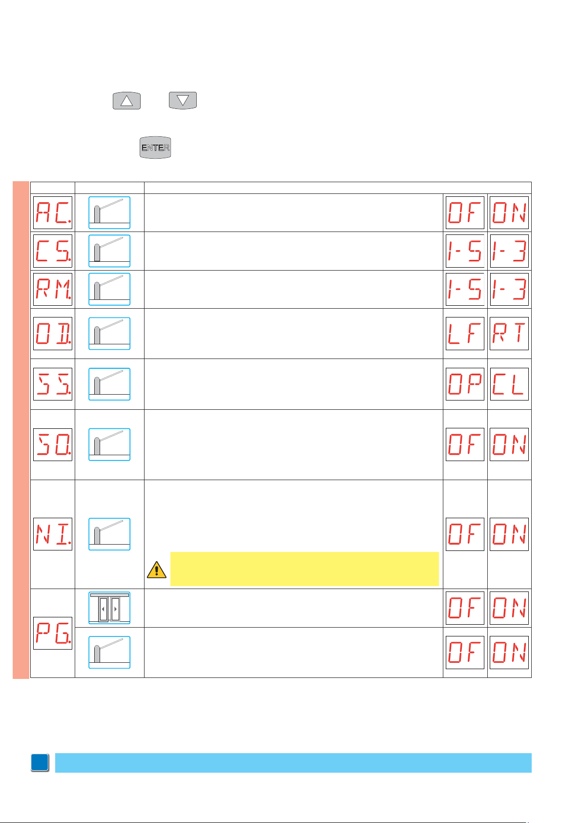
6.2 Second level menu - BC (Basic Configurations)
- use the keysŸandź to select the required function
- press the ENTER key to confirm
Display Application Description
AC - Enabling of automatic closing.
OF - Disabled
ON - Enabled
C5 - Step-by-step/opening command operation.
1-5 - Step-by-step
1-3 - Opening
RM - Radio receiver operation.
1-5 - Step-by-step
1-3 - Opening
OD - Opening direction selection.
LF - Opens towards left.
RT - Opens towards right.
The opening direction is intended by viewing the automation from the side being
examined.
SS - Selection of automation status at power on.
OP - Open
CL - Closed
Indicates how the control panel considers automation when powered up or after a
POWER RESET command.
SO - Enabling reversal safety switch function.
BC
OF - Disabled
ON - Enabled
When enabled (ON) with the automation blocked, if the contact 1-8 is open, any operation is impossible.
When disabled (OF) with the automation blocked, if the contact 1-8 is open, it is possible to activate the opening operation.
NI - Enabling of NIO electronic antifreeze system.
OF - Disabled
ON - Enabled
When enabled (ON) it maintains the efficiency of the motors even in low temperatures.
NOTE: for correct operation, the control panel must be exposed to the same ambient
temperature as the motors.
WARNING: it is necessary to set DIP5=OFF on the control panel in order to
make enabling/disabling of the NIO electronic anti-freeze system available
from the display module.
Do not use
PG - Enabling opening control reservation with interlocked barriers.
OF - Disabled
ON - Enabled
When enabled (ON), it requests the barrier 1 opening command if barrier 2 is engaged in completing the operation.
NOTE: it is possible that, owing to the type of automation and control panel, certain menus are not available.
i
8
IP1938EN - 2017-12-07
Page 9
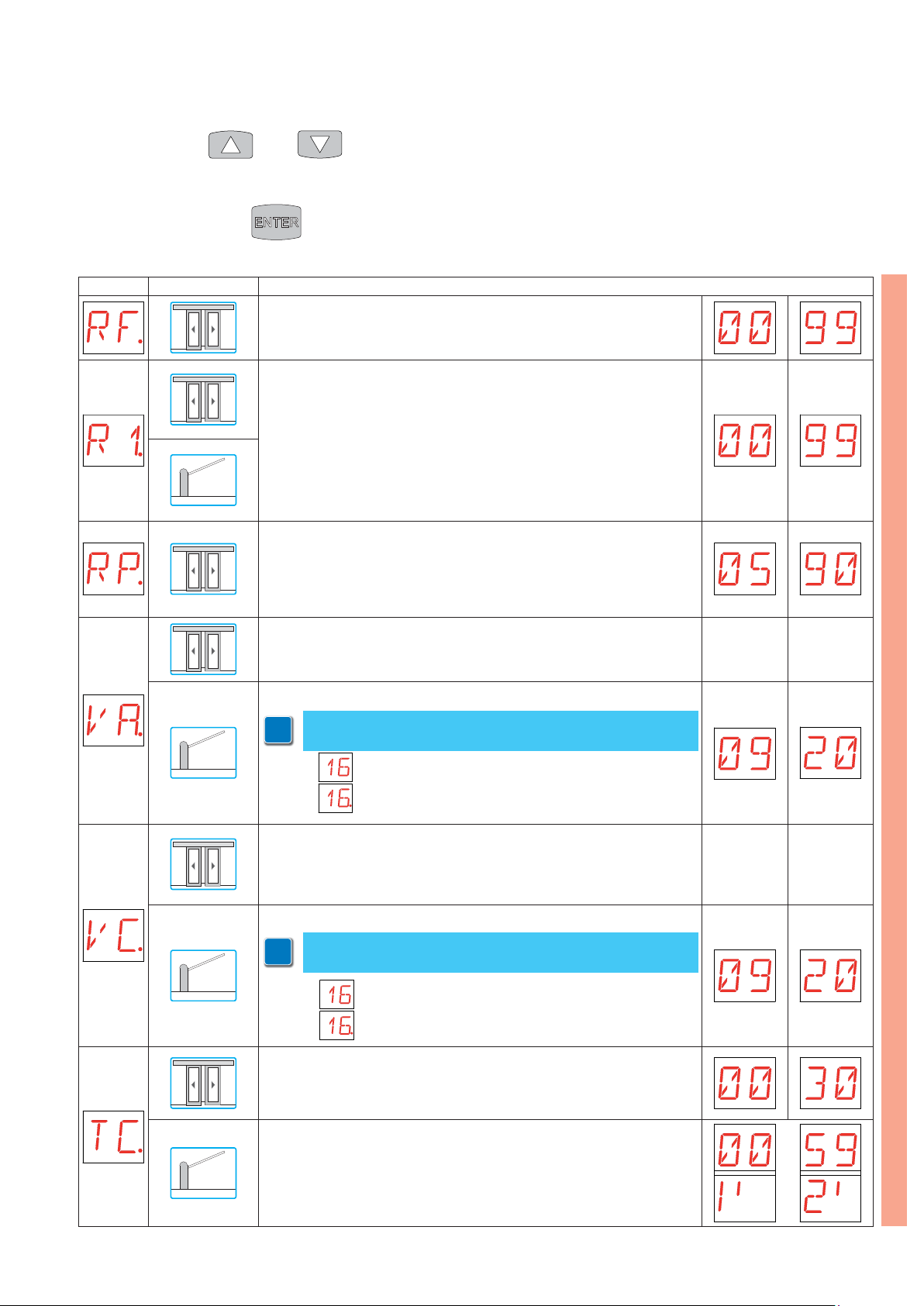
6.3 Second level menu - BA (Basic Adjustment)
- use the keysŸandź to select the required function
- press the ENTER key to confirm
Display Application Description
RF - Force adjustment. [%]
00 - Minimum
99 - Maximum
R1 - Thrust on obstacles adjustment. [%]
The control panel is equipped with a safety device that stops motion if an obstacle is encountered during an opening operation and either stops or reverses
motion during a closing operation.
00 - Minimum thrust
99 - Maximum thrust
RP - Partial opening adjustment. [%]
Adjusts the percentage of operation in relation to the total opening of the automation.
05 - Minimum
90 - Maximum
VA - Setting opening speed. [cm/s]
Setting opening speed. [°/s]
NOTE: adjustment occurs with a sensitivity interval of 0.5 °/s, indicated
i
by the switching on of the right-hand point.
Example:
VC - Setting closing speed. [cm/s]
VC - Setting closing speed. [°/s]
NOTE: adjustment occurs with a sensitivity interval of 0.5 °/s, indicated
i
by the switching on of the right-hand point.
= 16 degrees per second [°/s]
= 16,5 degrees per sec
ond [°/s]
MIN MAX
BA
MIN MAX
IP1938EN - 2017-12-07
Example:
TC - Setting automatic closing time. [s]
00 - Minimum
30 - Maximum
TC - Setting automatic closing time. [s]
Adjustment occurs with intervals of varying sensitivity.
- from 0” to 59” with 1 second intervals;
- from 1’ to 2’ with 10 seconds inter vals.
= 16 degrees per second [°/s]
= 16,5 degrees per sec
ond [°/s]
9
Page 10
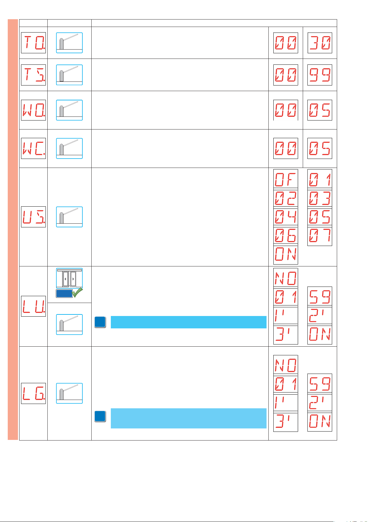
Display Application Description
TO - Setting the secondary automation opening time with interlocked barriers. [s]
00 - Minimum
30 - Maximum
TS - Setting renewal of automatic closing time after safety release. [%]
00 - Minimum
99 - Maximum
WO - Setting opening preflashing time. [s]
Adjustment of the lead time for the switch-on of the flashing light, in relation to
the start of the manoeuvre from a voluntary command.
00 - Minimum
05 - Maximum
WC - Setting closing preflashing time. [s]
Adjustment of the lead time for the switch-on of the flashing light, in relation to
the start of the manoeuvre from a voluntary command.
00 - Minimum
05 - Maximum
US - Selecting contact C-NO use.
OF - Contact C-NO always open
01 - Courtesy light or independent light
02 - Flashing light
(see QIK80EH installation manual)
03 - Barrier closed signalling
04 - Barrier open signalling
05 - Barrier operating signalling
06 - Barrier opening signalling
BA
07 - Barrier closing signalling
ON - Contact C-NO always closed
MP1
LU - Setting switch-on time for courtesy light. [s]
Adjustment occurs with intervals of varying sensitivity.
- from 1” to 59” with 1 second inter vals;
- from 1’ to 2’ with 10 seconds inter vals;
- from 2’ to 3’ with 1 minute inter val;
NO - Disabled
ON - Permanent switch-on, switch-off using radio command (only QIK80EH).
NOTE: the cour tesy light switches on at the start of each operation.
i
LG - Setting switch-on time for independent light. [s]
Adjustment occurs with intervals of varying sensitivity.
- from 1” to 59” with 1 second inter vals;
- from 1’ to 2’ with 10 seconds inter vals;
- from 2’ to 3’ with 1 minute inter val;
NO - Disabled
ON - Switch-on and switch-off using radio command.
NOTE: the switching on of the light does not depend on the star t of an
i
operation, but it is possible to control it separately using the relevant
transmitter key.
10
IP1938EN - 2017-12-07
Page 11
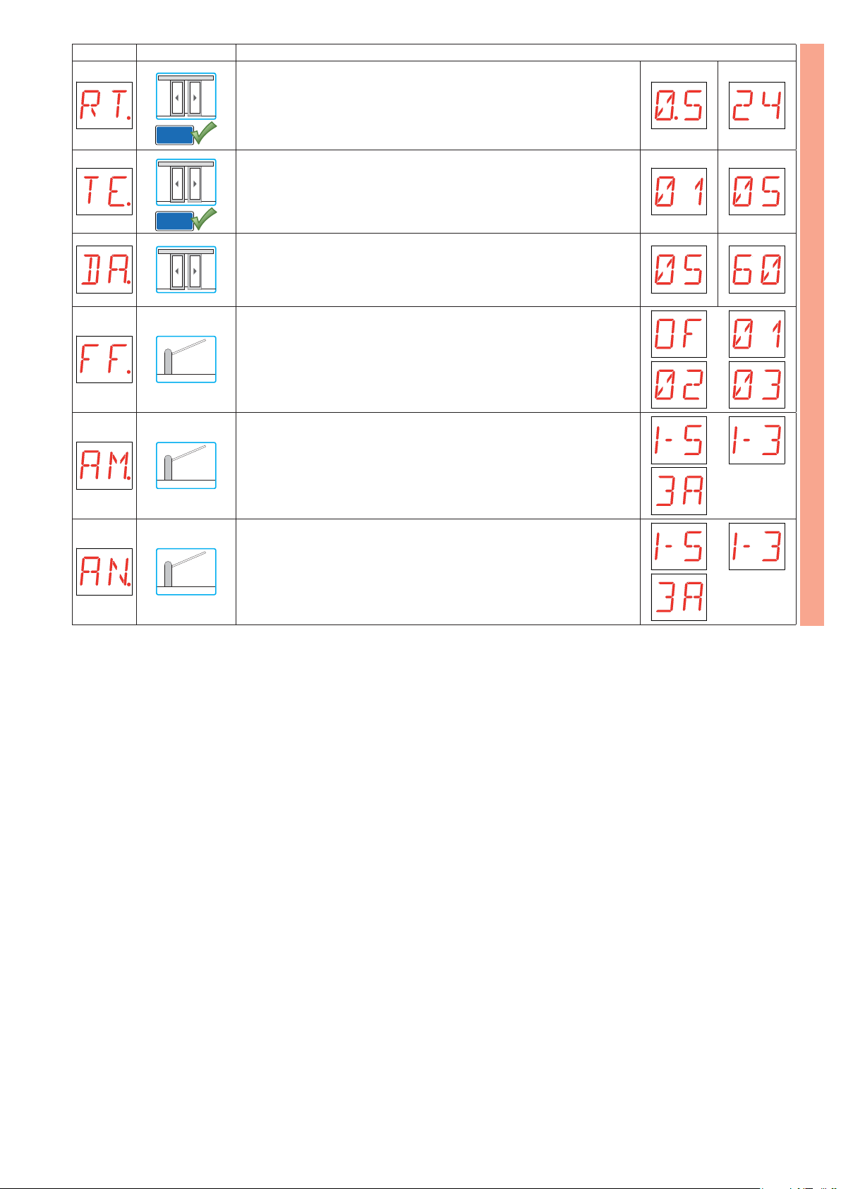
Display Application Description
RT - Setting the escape route mode test execution period [h]
0,5 - Minimum
24 - Maximum
EL21
TE - Setting the escape route mode temporary reinstatement time. [min]
01 - Minimum
05 - Maximum
EL21
DA - Setting the bi-directional mode duration time with delayed STOP. [s]
05 - Minimum
60 - Maximum
FF - Setting function of 0-14 exit.
OF - Exit disabled
01 - Flashing light
02 - Flashing light and electromagnetic block
(see QIK80EH installation manual)
03 - Electromagnetic block
AM - AUX1 coupling board operation.
1-5 - Step-by-step
1-3 - Opening
3A - Opening from inner side
BA
AN - AUX2 coupling board operation.
1-5 - Step-by-step
1-3 - Opening
3A - Opening from inner side
IP1938EN - 2017-12-07
11
Page 12
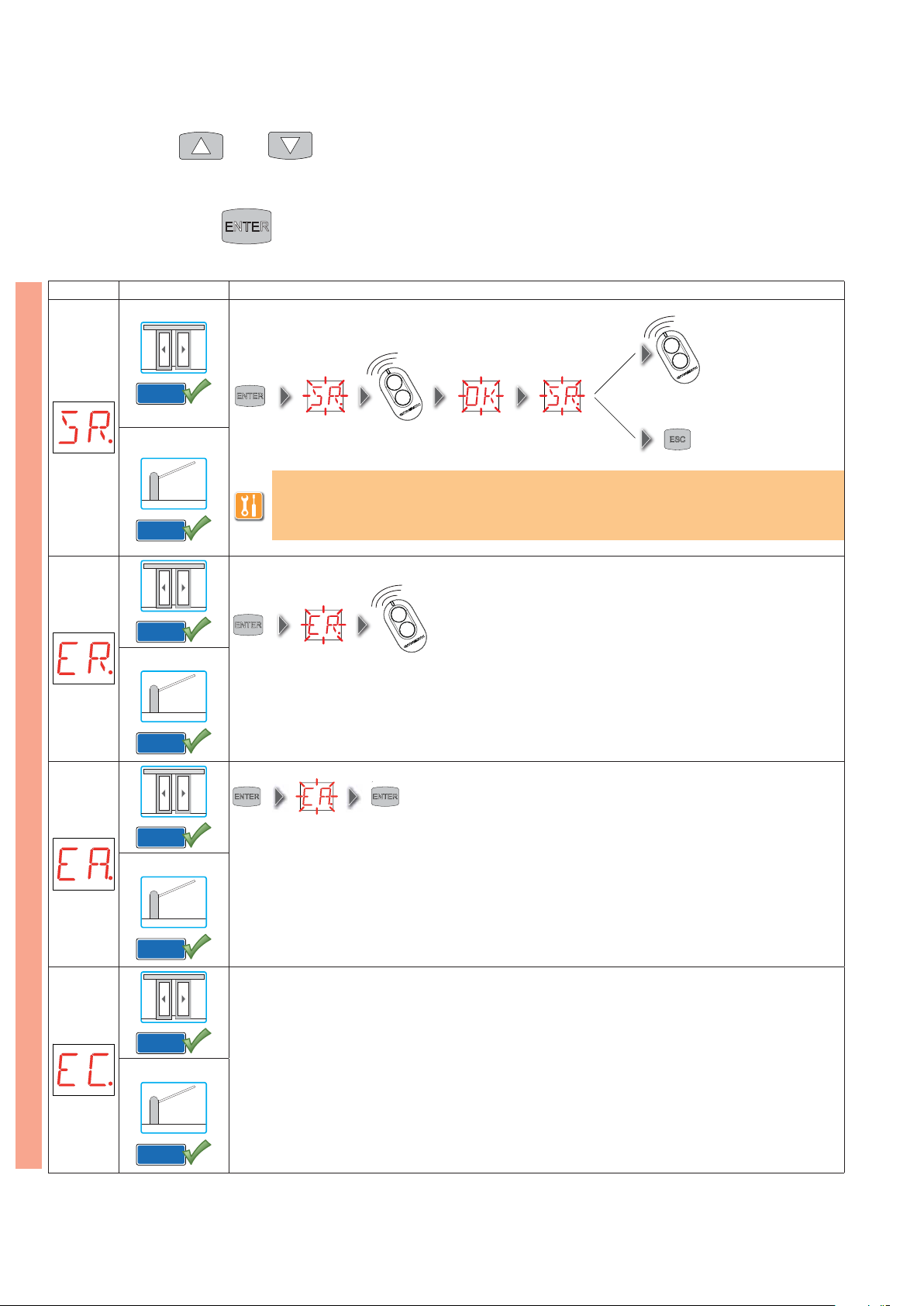
6.4 Second level menu - RO (Radio Operation)
- use the keysŸandź to select the required function
- press the ENTER key to confirm
Display Application Description
SR - Transmitter storage.
GOLR
It is possible to directly access the Transmitter storage menu even with the display turned off, but only
with the option Setting of display viewing mode set at 00 or 03:
- for transmitting a remote control not present in the memor y;
GOLR
- for transmitting an unstored channel of a remote control already present in the memory.
...x2, x3...
RO
GOLR
GOLR
GOLR
GOLR
ER - Single transmitter deletion.
2 s
EA - Total memory deletion.
2 s 2 s
EC - Single code deletion. (FUTURE USE)
GOLR
GOLR
12
IP1938EN - 2017-12-07
Page 13
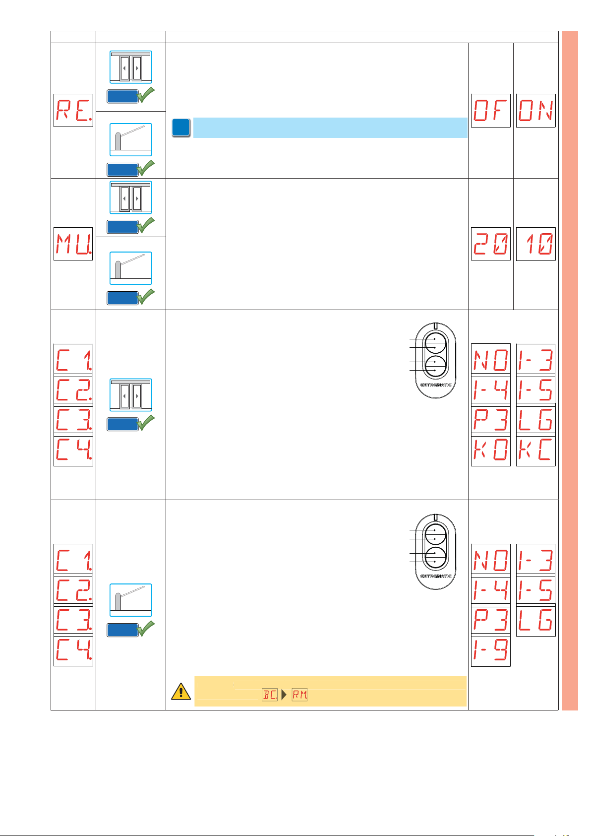
Display Application Description
G
RE - Setting memory opening from remote control.
OF - Disabled
ON - Enabled
When enabled (ON) remote programming is activated. To memorize new trans-
GOLR
GOLR
GOLR
GOLR
GOLR
mitters without using the control panel, press and hold down the PRG key of an
already-memorized GOL4 transmitter for 5 s until the LED switches on (within the
capacity of the receiver) and press any CH key of the new transmitter.
NOTE: make sure that undesired transmitters are not accidentaly memorized.
i
MU - Indication of maximum number of transmitters that can be stored in the
integrated memory.
It is possible to memorize up to 100 or 200 rolling code transmitters.
20 - 200 storable transmitters
10 - 100 storable transmitters
C1, C2, C3, C4 - Setting CH1, CH2, CH3, CH4 key function of memorized transmit-
ter.
NO - No setting selected
1-3 - Opening command
1-4 - Closing command
1-5 - Step-by-step command
P3 - Partial opening command
LG - Command to switch on/off the courtesy light
KO - KEY OPEN command (priority opening)
KC - KEY CLOSE command (priority closure, apart from NIGHT-TIME CLOSURE
mode).
If only one (any) CH key of the transmitter is stored, command KEY OPEN (priority
op ening) is car ried ou t. I f from t wo to fou r CH keys of a si ngle t ran smi tte r ar e stor ed,
the functions matched with the CH keys are as follows:
- CH1 = opening command 1-3;
- CH2 = partial opening command;
- CH3 = command to switch on/off the courtesy light;
- CH4 = KE Y OPEN command (priority opening).
C1, C2, C3, C4 - Setting CH1, CH2, CH3, CH4 key function of memorized transmitter.
NO - No setting selected
1-3 - Opening command
1-4 - Closing command
1-5 - Step-by-step command
P3 - Opening command of 1 automation
with interlocked barriers
LG - Command to switch on/off the cour tesy light
1-9 - STOP command
1 (Enter)
2 (∆)
3 (Esc)
4
1 (Enter)
2 (∆)
3 (Esc)
4
(∆)
RO
(∆)
IP1938EN - 2017-12-07
GOLR
If only one (any) CH key of the transmitter is stored, command 1-3 (opening/step-bystep) is carried out. If from two to four CH keys of a single transmitter are stored,
the functions matched with the CH keys are as follows:
- CH1 = command 1-3 opening/step-by-step;
- CH2 = no setting selected;
- CH3 = command to switch on/off the courtesy light;
- CH4 = STOP command.
WARNING: 1-3 (opening) and 1-5 (step-by-step) are binary options and are
WARNIN
dependent by the selection.
ependent by the selection.
13
Page 14
Display Application Description
.
W
o
.
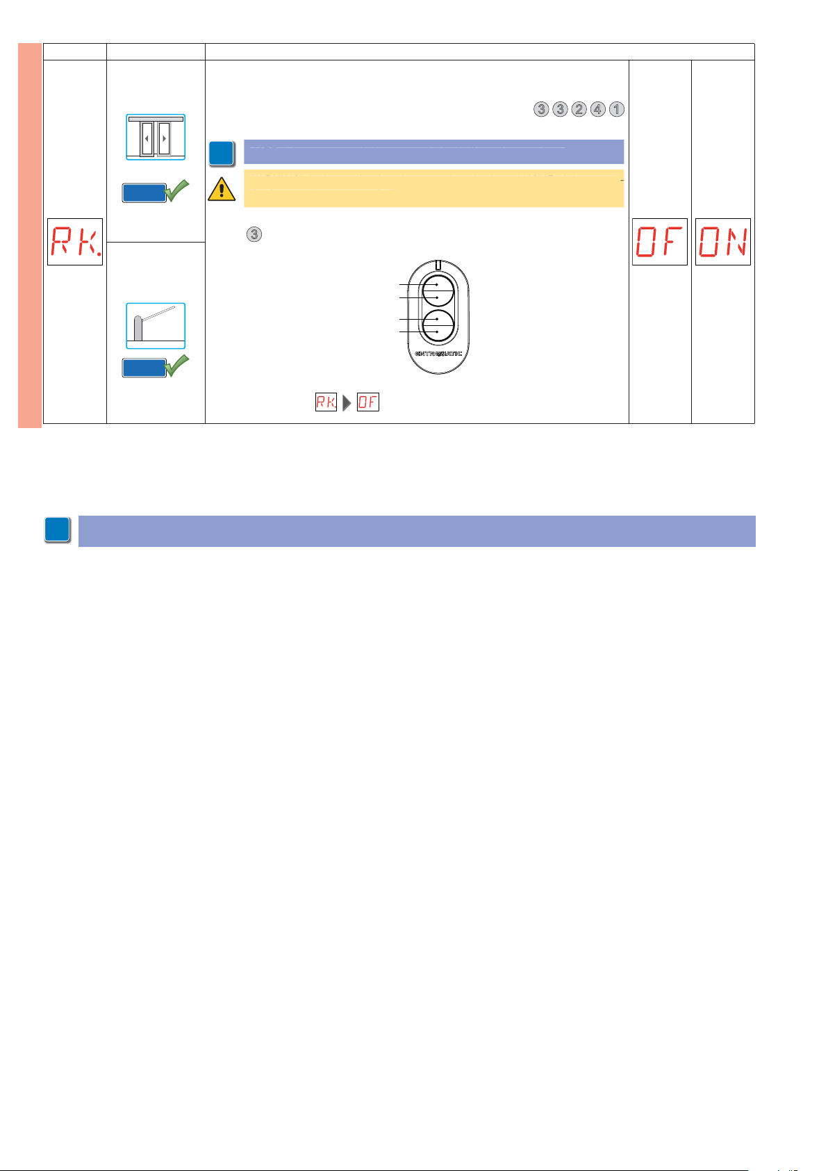
RK - Menu navigation via transmitter keyboard.
OF - Disabled
ON - Enabled
With the display switched off, quickly type the sequence of keys 3 3 2 4 1
using the desired memorized transmitter.
OTE: it is recommended to use a single dedicated transmitter
NOTE: it is recommended to use a single dedicated transmitter.
i
ARNING: during navigation via transmitter keyboard NONE of the mem
GOLR
WARNING: during navigation via transmitter keyboard NONE of the memo-
rized transmitters are active
rized transmitters are active.
RO
To test the new configuration, switch off the display and give an open command using key
GOLR
Navigation via transmitter keyboard is automatically disabled after 4 minutes of inactivity or by setting
NOTE: it is possible that, owing to the type of automation and control panel, certain menus are not available.
i
3
.
1 (Enter)
2 (∆)
3 (Esc)
(∆)
4
.
14
IP1938EN - 2017-12-07
Page 15
W
l
ibl
.
.
t
.
Wh
ibl
ade with J1
Wh
ibl
.
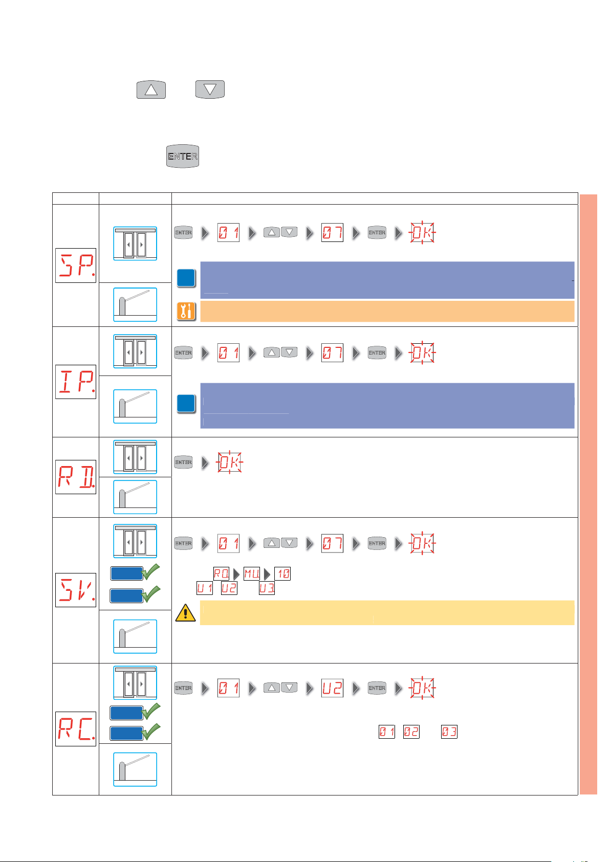
6.5 Second level menu - SF (Special Functions)
- use the keys Ÿ and ź to select the required function
- press the ENTER key to confirm
Display Application Description
SP - Setting the password.
(EXAMPLE)
NOTE: this setting is only possible when the password is not set.
OTE: this setting is only possible when the password is not set
The setting of the password prevents unauthorised personnel from accessing selections and adjust-
The setting of the password prevents unauthorised personnel from accessing selections and adjus
i
ments.
ments
It is possible to cancel the set password by selecting the sequence J1=ON, J1=OFF, J1=ON.
t is possible to cancel the set password by selecting the sequence J1=ON, J1=OFF, J1=ON.
IP - Inserting the password.
(EXAMPLE)
NOTE: this setting is only possible when the password is set.
TE: this setting is only possible when the password is set.
When the password is not inser ted, it is possible to access the visualization mode regardless of the
i
RD - Resetting factory settings (SETTINGS RESET).
2 s
SV - Saving user configuration on control panel storage module.
en the password is not inserted, it is poss
selection made with J1.
tion m
When the password is inserted, it is possible to access the maintenance mode.
en the password is inserted, it is poss
.
2 s
2 s
e to access the visualization mode regardless of the
e to access the maintenance mode
SF
IP1938EN - 2017-12-07
GOLR
BIXMR2
GOLR
BIXMR2
(EXAMPLE)
Selecting it is possible to save up to 3 personalized configurations in the memory posi-
tions
RC - Loading configuration.
It is possible to load the user configurations previously saved on the control panel storage module, or load
the predefined settings available in memory positions , and .
, and only with the storage module present on the control panel.
WARNING: if more than 100 transmitter codes are stored on the control panel storage module, it will
ARNING: if more than 100 transmitter codes are stored on the control panel storage module, it wil
not be possible to save any user configuration.
not be poss
e to save any user configuration
(EXAMPLE)
2 s
2 s
15
Page 16
Display Application Description
T
.
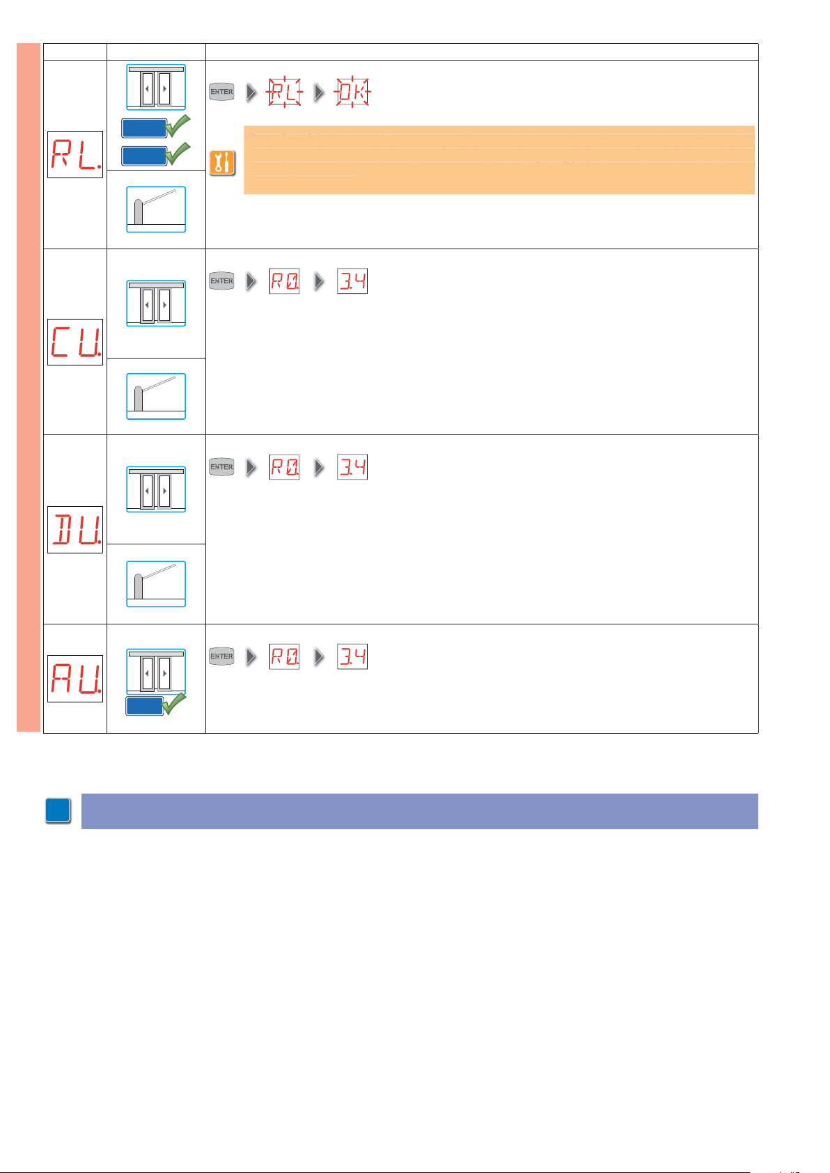
RL - Carica ultima configurazione impostata.
2 s
GOLR
BIXMR2
The MD1-MD2 display module automatically saves the last configuration set, and keeps it stored in
he MD1-MD2 display module automatically saves the last configuration set, and keeps it stored in
the integrated memory. In the event of a fault or replacement of the control panel, it is possible to
he integrated memory. In the event of a fault or replacement of the control panel, it is possible to
reset the automation configuration by connecting the MD1-MD2 display module and uploading the
reset the automation configuration by connecting the MD1-MD2 display module and uploading the
last configuration set.
last configuration set
CU - View of the control panel firmware version.
► release 0.3.4 (EXAMPLE)
SF
DU - View of the MD1-MD2 display module firmware version.
► release 0.3.4 (EXAMPLE)
AU - View of the MP1 accessory module firmware version.
► release 0.3.4 (EXAMPLE)
MP1
NOTE: it is possible that, owing to the type of automation and control panel, certain menus are not available.
i
16
IP1938EN - 2017-12-07
Page 17
6.6 Second level menu - CC (Cycles Counter)
- use the keys Ÿ and ź to select the required function
- press the ENTER key to confirm
Display Application Description
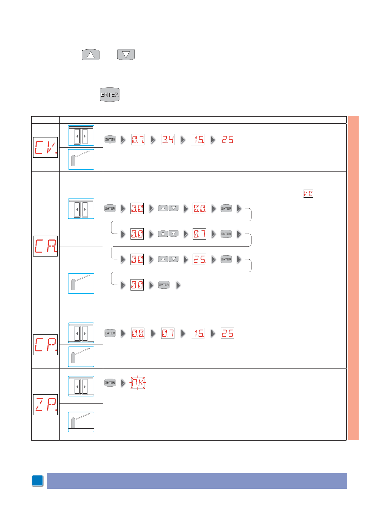
CV - View of the total manoeuvres counter.
CA - Setting maintenance alarm.
It is possible to set the required number of operations (regarding the partial manoeuvres counter) for
signalling the maintenance alarm.
When the set number of operations is reached, the display visualises the alarm message .
► 7.341.625 manoeuvres (EXAMPLE)
(EXAMPLE)
(EXAMPLE)
(EXAMPLE)
(00) (07) (25) (00) ► 72.500 manoeuvres (EXAMPLE)
2 s
CP - View of the par tial manoeuvres counter.
ZP - Resetting partial manoeuvres counter.
2 s
CC
► 71.625 manoeuvres (EXAMPLE)
NOTE: it is possible that, owing to the type of automation and control panel, certain menus are not available.
i
IP1938EN - 2017-12-07
To ensure correct operation, it is recommended to reset the partial manoeuvres counter:
- after each maintenance intervention;
- after each setting of the maintenance alarm interval.
17
Page 18
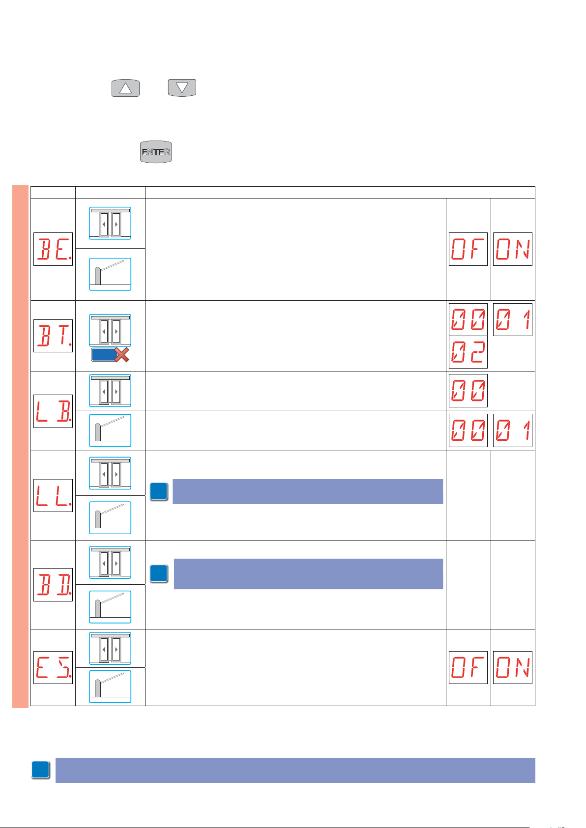
6.7 Second level menu - EM (Energy Management)
.
.
- use the keys Ÿ and ź to select the required function
- press the ENTER key to confirm
Display Application Description
BE - Advanced battery test enabling.
OF - Disabled
ON - Enabled
The advanced batter y test checks correct operation of the battery kit installed on
the automation.
BT - Selecting the battery mode.
00 - Anti-panic batteries with emergency opening.
01 - Continuity batteries with last opening operation.
02 - Continuity batteries with last closing operation.
EM
EL21
LB - Signalling of flat batteries.
00 - Display
LB - Signalling of flat batteries.
00 - Display
01 - QIKLUX light kit
LL - Setting the flat batteries signalling voltage threshold. [V ] (FUTURE USE)
NOTE: adjustment occurs with a sensitivity interval of 0.5 V, indicated by the
NOTE: adjustment occurs with a sensitivity interval of 0.5 V, indicated by the
i
switching on of the right-hand point.
witching on of the right-hand point
BD - Setting the batteries disconnection voltage threshold. [V]
TE: adjustment occurs with a sensitivity interval of 0.5 V, indicated by the
NOTE: adjustment occurs with a sensitivity interval of 0.5 V, indicated by the
i
switching on of the right-hand point.
witching on of the right-hand point
ES - Accessory power supply disconnection with automation stopped or in standby mode. (FUTURE USE)
MIN MAX
MIN MAX
NOTE: it is possible that, owing to the type of automation and control panel, certain menus are not available.
i
18
IP1938EN - 2017-12-07
Page 19
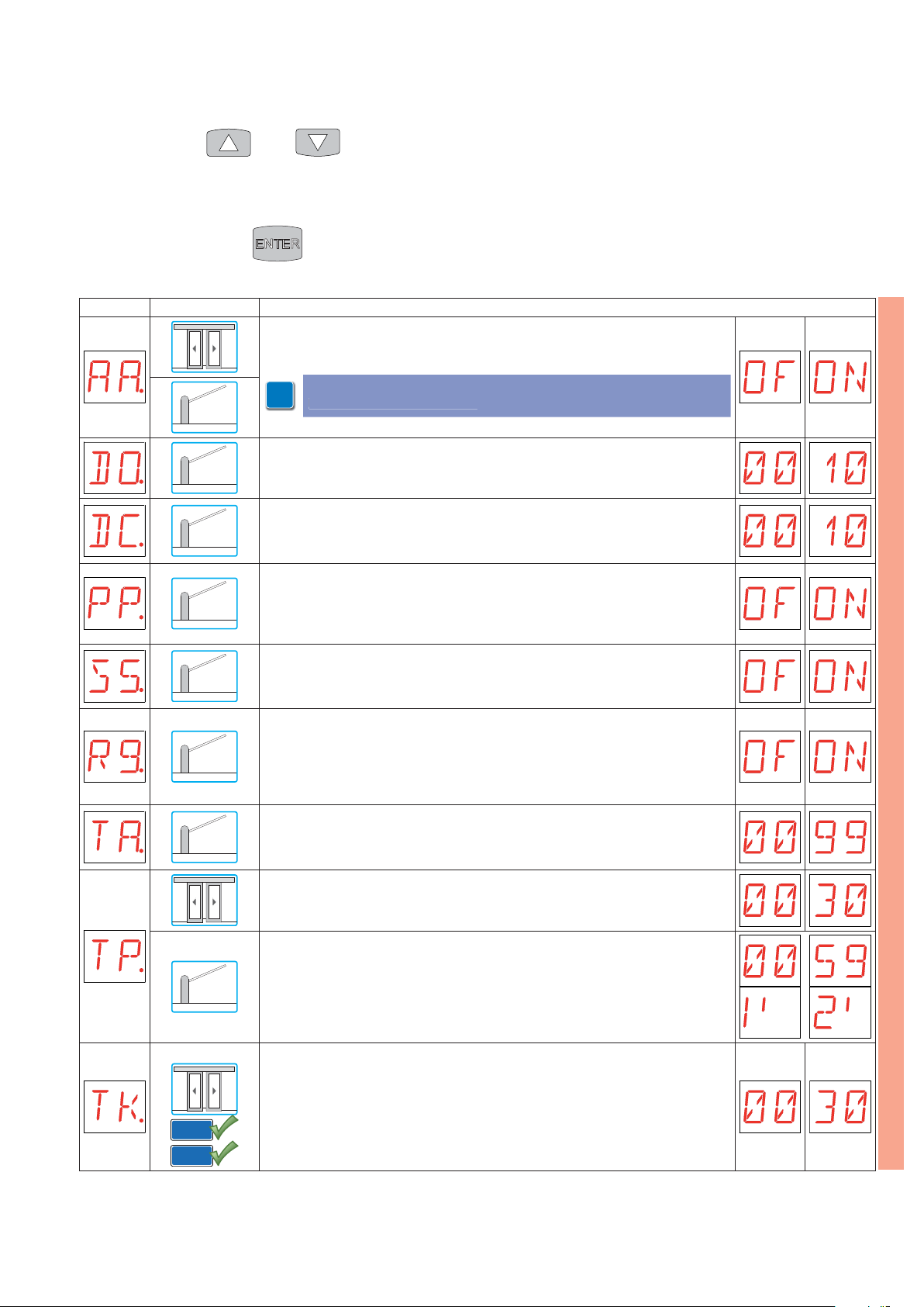
.
6.8 Second level menu - AP (Advanced Parameters)
- use the keys Ÿ and ź to select the required function
- press the ENTER key to confirm
Display Application Description
AA - Activation of AP (Advanced Parameters) menu.
OF - Disabled
ON - Enabled
NOTE: activation is necessary before being able to scroll through the AP
NOTE: activation is necessary before being able to scroll through the AP
i
(Advanced Parameters) menu.
Advanced Parameters) menu
DO - Setting of disengagement on obstacle during opening. [°]
00 - Minimum
10 - Maximum
DC - Setting of disengagement on obstacle during closing. [°]
00 - Minimum
10 - Maximum
PP - Setting of step-by-step sequence after command 1-5.
OF - Opening-Stop-Closing-Opening
ON - Opening-Stop-Closing-Stop-Opening
S5 - Duration of STOP in step-by-step sequence after command 1-5.
OF - Temporary
ON - Permanent
R9 - Activation of automatic closing after command 1-9 (STOP).
OF - Disabled
ON - Enabled
When enabled (ON) after a command 1-9 the automation carries out the automatic
closing (if enabled), after the set time.
TA - Setting the acceleration time. [%]
00 - Fast acceleration
99 - Slow acceleration
TP - Setting of automatic closing time after par tial opening. [s]
00 - Minimum
30 - Maximum
TP - Setting the automatic closing time after opening by P3 remote control (opening of 1 automation with inter-locked barriers). [s]
Adjustment occurs with intervals of varying sensitivity.
- from 0” to 59” with 1 second intervals;
- from 1’ to 2’ with 10 seconds inter vals.
AP
IP1938EN - 2017-12-07
TK - Setting of automatic closing time after key-operated opening. [s]
00 - Minimum
30 - Maximum
MP1
EL21
19
Page 20
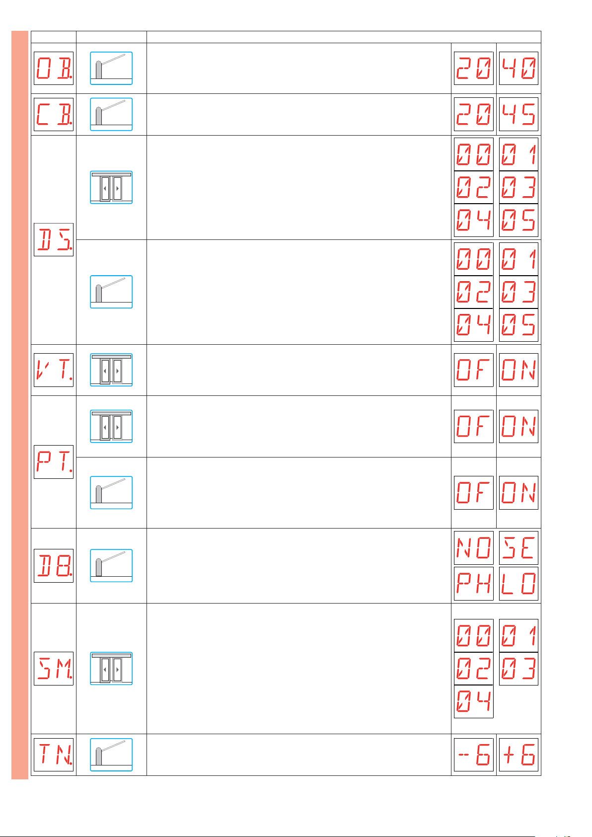
Display Application Description
OB - Setting opening deceleration. [°]
20 - Minimum
40 - Maximum
CB - Setting closing deceleration. [°]
20 - Minimum
45 - Maximum
DS - Setting of display viewing mode.
00 - No display
01 - Selector settings (see paragraph 7.1)
02 - Automation status (see paragraph 7.2)
03 - Commands and safeties (see paragraph 7.3)
04 - Working temperature (DO NOT USE)
05 - Battery voltage (DO NOT USE)
DS - Setting of display viewing mode.
00 - No display
01 - Commands and safeties with radio range test (see paragraph 7.3)
02 - Automation status (see paragraph 7.2)
03 - Commands and safeties (see paragraph 7.3)
04 - Working temperature (DO NOT USE)
05 - Battery voltage (DO NOT USE)
AP
VT - Setting of variable automatic closing time according to foot traffic.
OF - Disabled
ON - Enabled
The automation automatically adjusts the variable closing time according to the intensity of pedestrian traffic present.
PT - Passage from par tial to total opening according to foot traffic.
OF - Disabled
ON - Enabled
The automation automatically switches from Partial opening to Total opening and
vice versa depending on the intensity of pedestrian traffic.
PT - Automatic opening repositioning command.
OF - Disabled
ON - Enabled
When enabled (ON) with the barrier open, the rod is automatically repositioned to a
fully open position if the rod is moved to a closing position by external forces (wind,
snow, etc.).
D8 - Selection of device connected to terminals 1-8.
NO - None
SE - Safety edge
PH - Photocells
LO - Magnetic loop
SM - Selecting the operation mode of the opening safety sensors.
00 - The opening of the contact causes the opening speed to decrease in the last 500
mm of stroke of the door wing.
01 - The opening of the contact causes the opening operation to stop in the last 100
mm of stroke of the door wing.
02 - The opening of the contact causes the opening operation to stop in the last 70
mm of stroke of the door wing.
03 - The opening of the contact causes the opening speed to decrease in the last 500
mm of stroke of the door wing and the opening operation to stop in the last 100 mm
of stroke of the door wing.
04 - The opening of the contact causes the opening speed to decrease in the last 500
mm of stroke of the door wing and the opening operation to stop in the last 70 mm
of stroke of the door wing.
TN - Setting intervention temperature for NIO electronic antifreeze system. [°C]
Adjustment of the working temperature of the control panel.
The value does not refer to outside temperature.
20
IP1938EN - 2017-12-07
Page 21
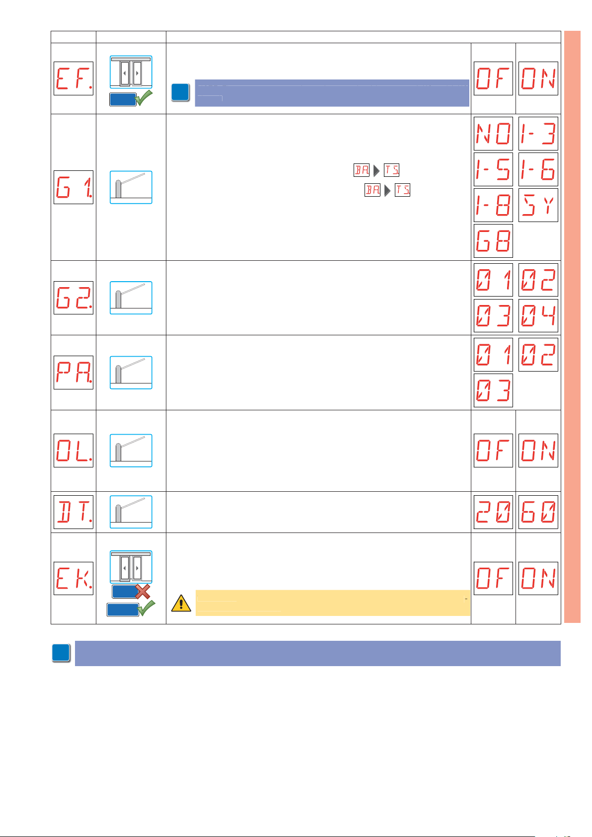
Display Application Description
selector installed
EF - Setting the escape route mode.
OF - Disabled
ON - Enabled
NOTE: The escape route mode can be set only with contacts 1-KO and 1-KC
NOTE: The escape route mode can be set only with contacts 1-KO and 1-KC
i
osed.
EL21
closed.
G1 - Setting the G1 input mode.
NO - Input disabled
1-3 - Input 1-3 (opening)
1-5 - Input 1-5 (step-by-step)
1-6 - Input 1-6 (safety stop)
1-8 - Input 1-8 (safety re-opening) dependent on the setting
SY - Synchronism input
G8 - Input 1-8 (safety re-opening) not dependent on the
G2 - Setting the rod lighting kit.
01 - On with barrier closed, off with barrier open, flashing with barrier operating.
02 - On with barrier closed, on with barrier open, flashing with barrier operating.
03 - Flashing with barrier closed, off with barrier open, flashing with barrier operating.
04 - Flashing with barrier closed, on with barrier open, flashing with barrier operating.
PA - Setting the automations parallel mode.
01 - Simultaneous automations
(see QIK80EH installation manual)
02 - Interlocked one-way automations without presence
03 - Interlocked one-way automations with presence
setting
AP
OL - Selecting the gate open indicator light mode.
OF - Flashing
ON - Switched on
When set OF, the light is switched off when the automation is closed, is switched
on when the automation is open, is flashing during the opening and closing phases.
When set ON, the light is switched off when the automation is closed, is switched on
when the automation is open and during the opening and closing phases.
DT - Setting the stopped barrier detection time. [ms]
20 - Minimum
60 - Maximum
EK - Selecting electric block operation.
OF - Normal
ON - Contact 1-28 can be managed from the terminal board of the control panel in
mono-directional or bi-directional operation (blocking can be enabled/disabled with
mono-directional operation).
EL21
COME
NOTE: it is possible that, owing to the type of automation and control panel, certain menus are not available.
i
WARNING: the selection is available only with the COME electronic func
WARNING: the selection is available only with the COME electronic func-
ns
tions selector installed.
.
IP1938EN - 2017-12-07
21
Page 22
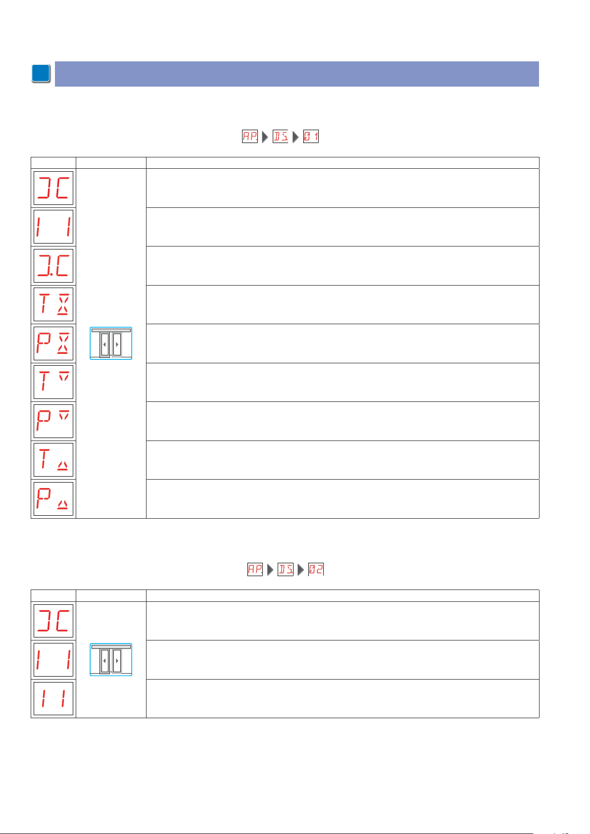
7. Display viewing mode
NOTE: it is possible that, owing to the type of automation and control panel, certain menus are not available.
i
7.1 Viewing of Selector settings
To enable the display mode Selector settings, select
Display Application Description
Automation closed.
Automation open.
Night function enabled.
Bi-directional total opening.
Bi-directional par tial opening.
Mono-directional total opening.
Mono-directional partial opening.
Reversed mono-directional total opening.
Reversed mono-directional partial opening.
7.2 Viewing of Automation status
To enable the display mode Automation status, select
Display Application Description
Automation closed.
Automation open.
Automation stopped in intermediate position.
22
IP1938EN - 2017-12-07
Page 23
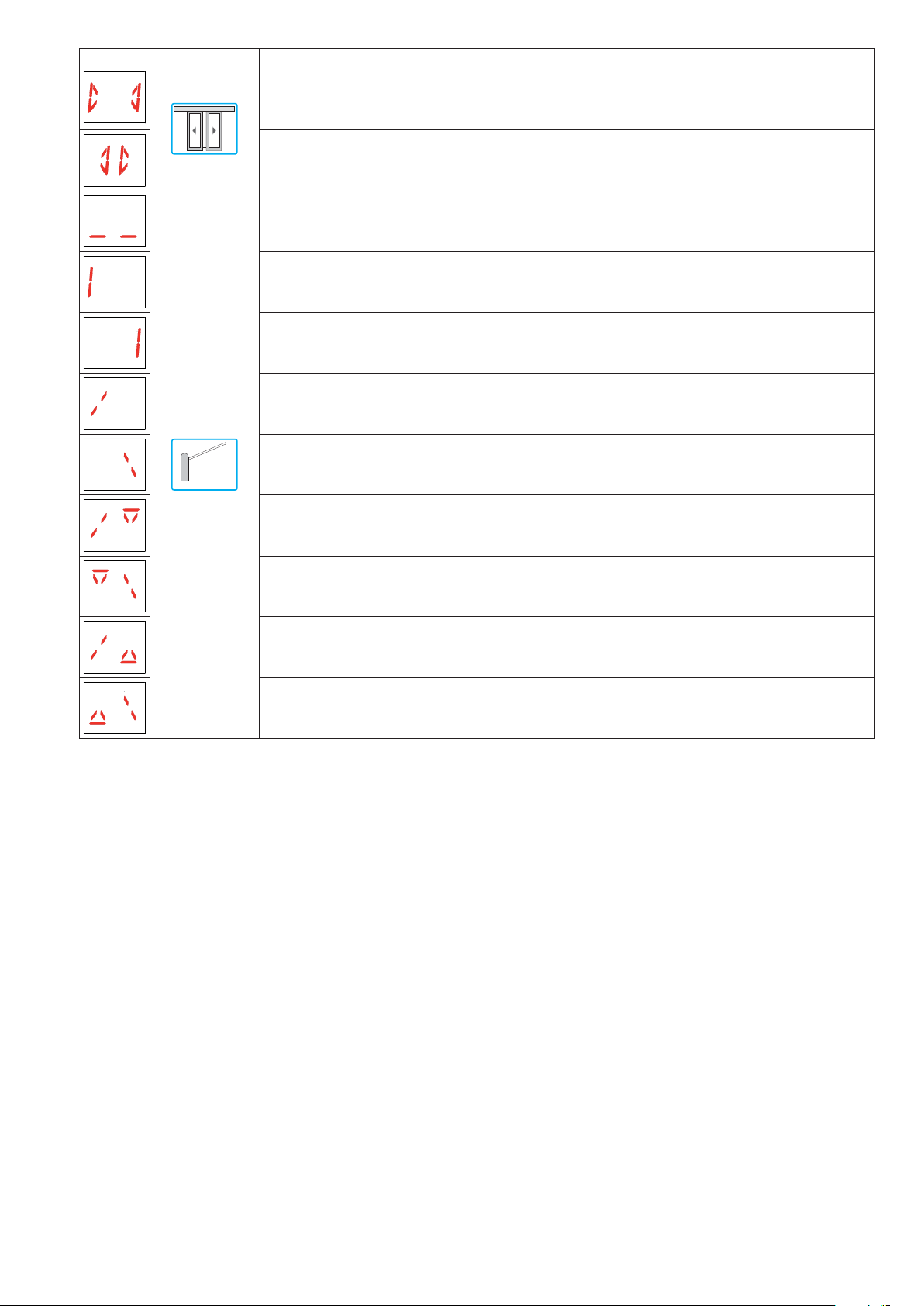
Display Application Description
Automation closing.
Automation opening.
Automation closed.
Automation open from left side.
Automation open from right side.
Automation in intermediate position from left side.
Automation in intermediate position from right side.
Automation closing from left side.
Automation closing from right side.
Automation opening from left side.
Automation opening from right side.
IP1938EN - 2017-12-07
23
Page 24
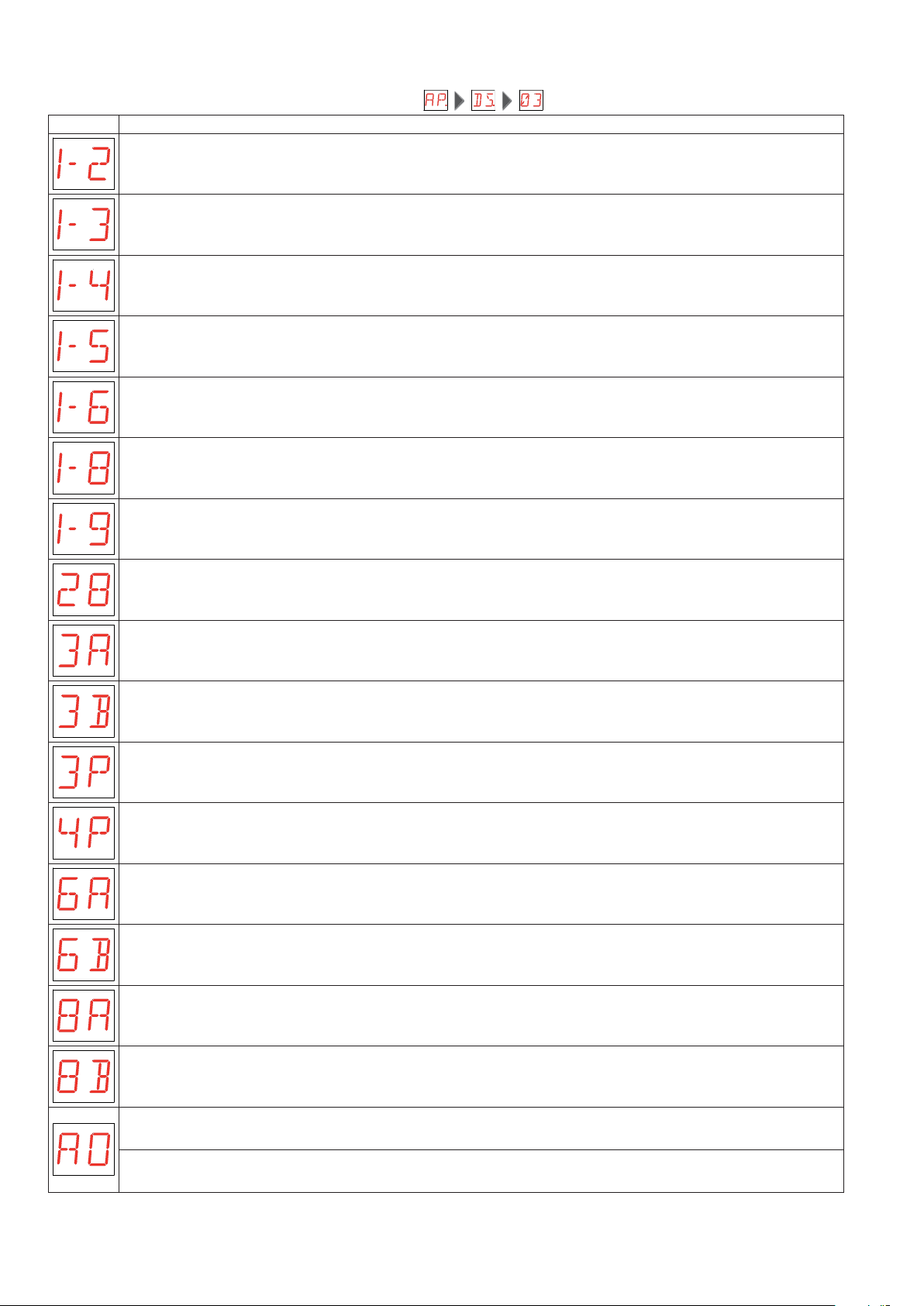
7.3 Viewing of Commands and safeties
To enable the display mode Commands and safeties, select
Display Description
Automatic closing activation command.
Opening command.
Closing command.
Step-by-step command.
Safety with slowed opening.
Safety with closing reversal.
STOP command.
Block activation command.
Inner side opening command.
Outer side opening command.
Hold-to-run opening command.
Hold-to-run closing command.
Safety with slowed opening sensor A.
Safety with slowed opening sensor B.
Safety with closing reversal sensor A.
Safety with closing reversal sensor B.
Auxiliary opening command.
Opening command with interlocked barriers reservation.
24
IP1938EN - 2017-12-07
Page 25
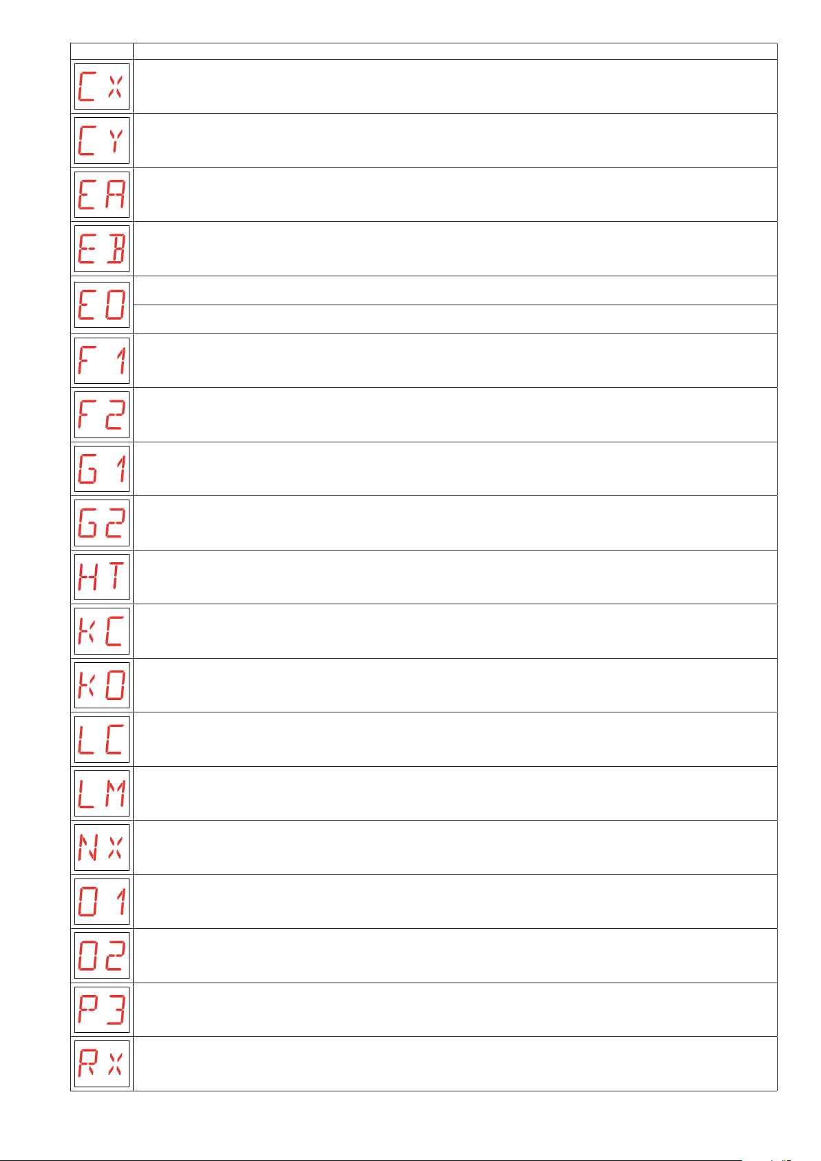
Display Description
AUX1 coupling board command reception.
AUX2 coupling board command reception.
Enabling opening from inner side.
Enabling opening from outer side.
EMERGENCY OPEN command for emergency opening.
Automatic opening repositioning command.
Enabling opening (regardless of the opening direction) limit switch.
Enabling closing ( (regardless of the opening direction) limit switch.
GENERAL PURPOSE 1 command.
GENERAL PURPOSE 2 command - Fire alarm.
Heating of the motors (NIO function) in progress.
Priority key-operated closing KEY CLOSE command.
Priority key-operated opening KEY OPEN command.
Light activation command.
Light mode selection command.
Radio reception (of any CH key not stored).
Obstacle detection by overcurrent.
Obstacle detection by automation stopped.
Partial opening command.
Radio reception (of any stored transmitter CH key present in the memory).
IP1938EN - 2017-12-07
25
Page 26
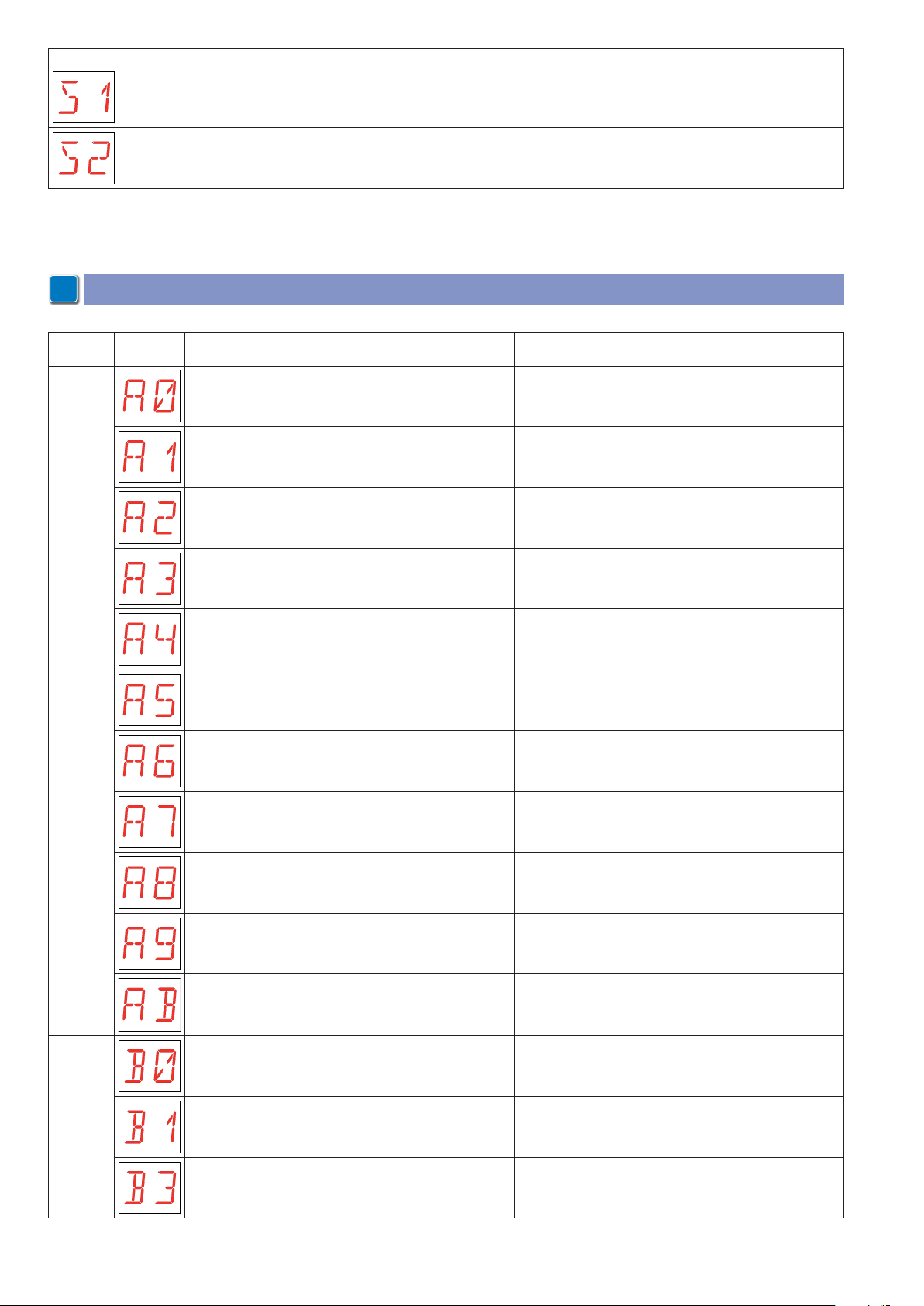
Display Description
Microswitch 1 command.
Microswitch 2 command.
7.4 Viewing of alarms and faults
NOTE: the signaling of alarm messages takes priority over all other displays.
i
Type of
alarm
Accessories alarm
Display Description Remedy
Test of safety sensor installed on terminal 6 failed. Check the wiring and correct operation of the safety sensor.
Test of safety sensor installed on terminal 6A failed. Check the wiring and correct operation of the safety sensor.
Test of safety sensor installed on terminal 6B failed. Check the wiring and correct operation of the safety sensor.
Test of safety sensor installed on terminal 8 failed. Check the wiring and correct operation of the safety sensor.
Test of safety sensor installed on terminal 8A failed. Check the wiring and correct operation of the safety sensor.
Test of safety sensor installed on terminal 8B failed. Check the wiring and correct operation of the safety sensor.
Integrated photocells malfunctioning. Check that the photocells are clean and operating correctly.
Incorrect connection of terminal 9 to terminal 41. Connect contact 1-9 as shown.
Shortcircuiting of the flashing light driver. Contact Technical Assistance.
Current overload on flashing light output. Check correct connection of the flashing light to terminals
0-14.
Short-circuit detection on open gate indicator light Check the wiring and the correct functioning of the gate
indicator light.
Batteries almost flat. Restore power supply or replace the battery kit.
Flat batteries. Restore power supply or replace the battery kit.
Batteries alarm
Batteries not connected or absent. Check correct connection of the batter y kit to the control
panel or disable the advanced battery test (if not present).
26
IP1938EN - 2017-12-07
Page 27
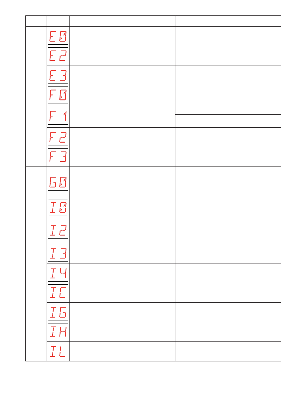
Type of
alarm
Display Description Remedy
Encoder fault. If the alarm continues, contact Technical Assistance.
Reversal of the motor leads. Check the motor leads.
Encoder alarm
Functional alarm
functions
Emergency
Encoder disconnected, false encoder contacts, encoder
fault.
Detection of irregular overspeed. Perform POWER RESET with command 1-29 or using the
Failed closing of the door wings for executing the escape
route mode test.
Door wings opening failed. Manually check that the door wings move freely and ad-
High internal temperature.
When the internal temperature is high, the automation
operates at low speed.
Activation of the EMERGENCY OPEN command. Check that 1-EO contact is closed.
Fault at EMERGENCY OPEN input. Check operation of the control panel.
Check that the encoder is connected correctly, clean the
contacts by connecting and disconnecting the encoder
plug on the contacts, replace encoder.
functions selector (if present).
If the alarm continues, contact Technical Assistance.
Manually check that the door wings move freely.
Check the activation of safety photocells and sensors.
just the door wings height.
/
If the alarm continues, contact Technical Assistance.
Control panel internal error
Control panel internal error
Failed internal bus communication. Check operation of the control panel.
No master/slave presence with automations in simultaneous synchronism.
Internal radar input fault. Check operation of the control panel.
Factory initialization incomplete. Contact Technical Assistance.
Operation time-out error. Perform POWER RESET with command 1-29 or using the
Motor drive fault. Perform POWER RESET with command 1-29 or using the
Motor currents fault. Perform POWER RESET with command 1-29 or using the
EL21 batter y fault
EL21 block fault
AUX motor coil fault
Check correct power supply of the automations.
If the alarm continues, contact Technical Assistance.
functions selector (if present).
functions selector (if present).
If the alarm continues, contact Technical Assistance.
functions selector (if present).
If the alarm continues, contact Technical Assistance.
Check the functioning of the EL21 control panel.
Check the functioning of the AUX motor coil.
If the alarm continues, contact Technical Support.
IP1938EN - 2017-12-07
27
Page 28
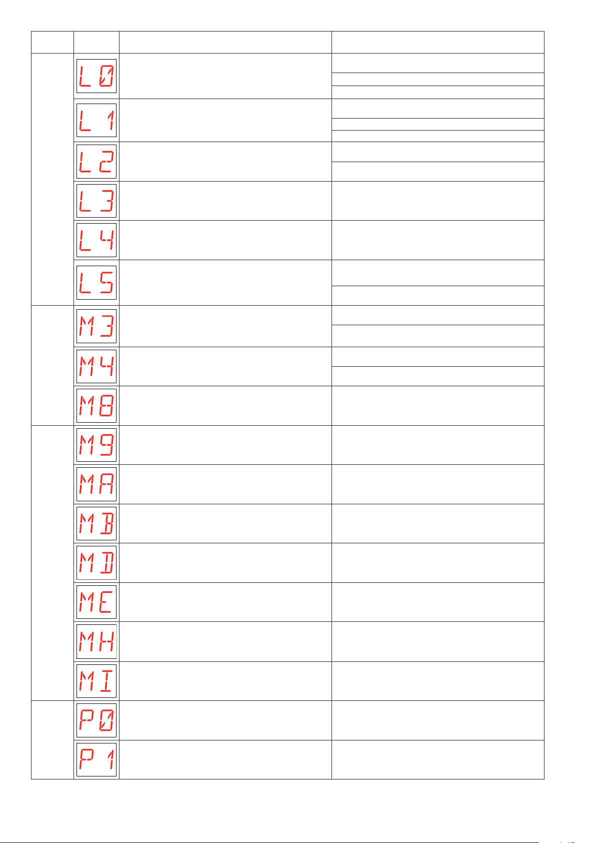
Type of
alarm
Display Description Remedy
Door wings release failed. Check the wiring of the blocking device and microswitch.
Check microswitch operation.
Check blocking device movement.
Door wings locking failed. Check the wiring of the blocking device and microswitch.
Check microswitch operation.
Check blocking device movement.
Auxiliary coil shor t circuit. Check the wiring of the bistable blocking device.
Check operation of the bistable blocking device.
Auxiliary coil not connected. Check the wiring of the bistable blocking device.
Blocking device alarm
Mechanical alarm
Main coil not connected. Check the wiring of the blocking device.
Main coil short circuit. Check the wiring of the blocking device.
Check operation of the blocking device.
Automation blocked. Check operation of the blocking device.
Check for the presence of obstacles near the mechanical
stops.
Motor short circuit. Check correct connection of the motor.
Check correct operation of the motor.
Door dimension error.
Door too long.
Door dimension error.
Door too short.
Stop exceed error. Perform POWER RESET with command 1-29 or using the
Check the transmission belt.
Manually check that the door wings move freely.
functions selector (if present).
Absence of motor during an operation. Check correct connection of the motor.
Irregular operation of the opening limit switch. Check correct connection of the opening limit switch.
Mechanical alarm
alarm
Power supply
Irregular operation of the closing limit switch. Check correct connection of the closing limit switch.
Incorrect functioning of the elastic in the EL21 control
panel.
Detection of the third consecutive obstacle. Check for the presence of permanent obstacles along the
No power supply. Check that the control panel is powered correctly.
Mains voltage too low. Check the automation power supply voltage.
Check the elastic on the door.
stroke of the automation.
28
IP1938EN - 2017-12-07
Page 29
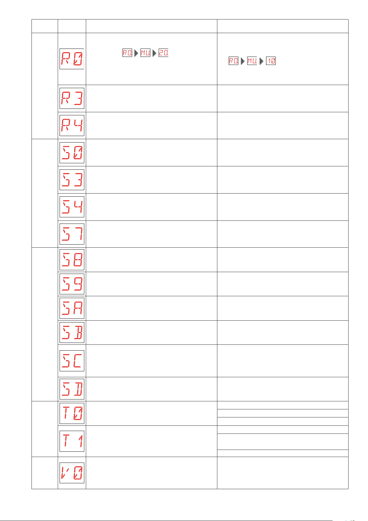
Type of
alarm
Display Description Remedy
Insertion of a memory module containing more than 100
memorized transmitters.
WARNING: the setting is automatic.
Memor y module not detected. Insert a memory module.
To save the set configurations in the memory module,
cancel a few memorized transmitters to bring the total
lower than 100.
Set
.
Radio operations alarm
Settings alarm
Memor y module not compatible with control panel. Insert a memory module compatible with control panel.
Blocking device settings error. Check the blocking device settings on the control panel.
Operation mode setting error. Check the operation mode set on the COMER-COMKR
functions selector.
COMKR mechanical functions selector fault or connection error.
COMER electronic functions selector KEY contacts connection error.
COMER electronic functions selector enabled. Disable the COMER electronic functions selector.
Closing commands setting not compatible with the escape route mode.
Check correct connection of the COMKR mechanical
functions selector.
Check that the KE Y contacts of the COMER electronic
functions selector and 1-G1 on the control panel are both
connected and are enabled/disabled at the same time.
Check closing commands.
Settings alarm
alarm
Redundancy test
alarm
Service
R1 trimmer not enabled. Perform the trimmer enabling procedure.
If the alarm continues, contact Technical Assistance.
VA trimmer not enabled. Perform the trimmer enabling procedure.
If the alarm continues, contact Technical Assistance.
VC trimmer not enabled. Perform the trimmer enabling procedure.
If the alarm continues, contact Technical Assistance.
Trimmer enabling procedure not valid. Perform the trimmer enabling procedure.
If the alarm continues, contact Technical Assistance.
Main motor test failure. (Insuf ficient movement dur in g the
redundancy test).
Auxiliary motor test failure. (Insufficient movement during
the redundancy test).
Request for maintenance intervention. Proceed with the routine maintenance intervention.
Check the wiring of the main motor.
Check operation of the main motor.
Manually check that the door wings move freely.
Check the wiring of the auxiliary motor.
Check operation of the auxiliary motor.
Manually check that the door wings move freely.
IP1938EN - 2017-12-07
29
Page 30

All the rights concerning this material are the exclusive property of Entrematic Group AB.
Although the contents of this publication have been drawn up with the greatest care, Entrematic Group AB cannot be held responsible in any way for any damage
caused by mistakes or omissions in this publication. We reserve the right to make changes without prior notice.
Copying, scanning and changing in any way are expressly forbidden unless authorised in writing by Entrematic Group AB.
30
IP1938EN - 2017-12-07
Page 31

IP1938EN - 2017-12-07
31
Page 32
IP1938EN - 2017-12-07
Entrematic Group AB
Lodjursgatan 10
SE-261 44, Landskrona
Sweden
www.entrematic.com
 Loading...