

Page 1

Ditec EL21
IP2149EN
Control panel installation manual for Ditec VALORR-TENR
automations installed in escape routes
Transformer
-
24V output 0,5 A
+
Opening, inner side
Closing safety device, inner side
-
24V output 0,5 A
+
Outer side opening
Closing safety device, outer side
Opening safety device
Opening safety device
X
Motor
24V=
S
F1
E
0LN
F
U
Power supply
OPEN
BIXMR2
1ON234
MD1 COMER
1
4 5 6
01
2
R- R+ 8A
INTERNAL
SENSOR
REMOTE
012122
X
3
41 12AB9272901
3B 8B 41016A 6B 41
EXTERNAL
SENSOR
POWER
ALARM
IN
SA
1EO 1AO
OPEN
SAFETY
GENERAL
PURPOSE
1KOKC 1G1G2
ROTARY
FUNCTION
SELECTOR
MOT2
AUX
X
Key-operated closing
Key-operated opening
Auxiliary opening
Emergency opening
www.ditecentrematic.com
ENC
+
BUZZER
MOT
POWER
-
X
X
BAT
X
+
-
BAT
+
+
AUX
-
0R1SR R2
+
LK
-
Install the supplied ferrites
X
as shown
Page 2
Contents
i
Subject Page
1. General safety precautions 21
2. EC Decl aration of Conformity 22
3. Technical specifications 22
3.1 Applications
4. Electrical connections 23
4.1 Safety functions 23
4.2 Electromagnetic emissions 23
4.3 Electrical connections with COMER selector 24
4.4 Electrical connections with COMKR selector
5. Commands 26
6. Outputs and accessories 28
7. Adjustments 30
7.1 Dip-switches 30
7.2 Signals 30
8. Escape route sensor 31
9. Autocontrolled safety sensor 31
10. Star t-up 32
11. Troubleshooting 33
22
25
Key
This symbol indicates instructions or notes regarding safety, to which special attention must be paid.
This symbol indicates useful information for the correct functioning of the product.
All the rights concerning this material are the exclusive property of Entrematic Group AB.
Although the contents of this publication have been dr awn up with the greatest care, Entrematic Group AB
cannot be held responsible in any way for any damage caused by mistakes or omissions. We reserve the
right to make changes without prior notice.
Copying, scanning and changing in any way are expressly forbidden unless authorised in writing by Entrematic
Group AB.
20
IP1951EN - 2014-10-06
Page 3

1. General safety precautions
“Important instructions for installation safety.
Incorrect installation can cause serious injury”
This installation manual is intended for qualified personnel only.
Installation, electrical connections and adjustments must be performed in accordance
with Good Working Methods and in compliance with the present standards.
Read the instructions carefully before installing the product. Bad installation could
be dangerous.
The packaging materials (plastic, polystyrene, etc.) should not be discarded in
the environment or left within reach of children, as they are a potential source
of danger.
Before installing the product, make sure it is in perfect condition.
Do not install the product in explosive areas and atmospheres: the presence of inflammable gas or fumes represents a serious safety hazard.
The safety devices (photocells, safety edges, emergency stops, etc.) must be installed
taking into account: applicable laws and directives, Good Working Methods, installation premises, system operating logic and the forces developed by the automation.
Before connecting the power supply, make sure the plate data correspond to that
of the mains power supply. An omnipolar disconnection switch with a contact
opening distance of at least 3mm must be fitted on the mains supply.
Check that there is an adequate residual current circuit breaker and a suitable overcurrent cutout upstream of the electrical installation in accordance with Good Working
Methods and with the laws in force.
When requested, connect the automation to an effective earthing system that complies
with current safety standards.
During installation, maintenance and repair operations, cut off the power supply before
opening the cover to access the electrical parts.
The electronic parts must be handled using earthed antistatic conductive arms.
The manufacturer of the motorisation declines all responsibility if component
parts not compatible with safe and correct operation are fitted.
Only use original spare parts for repairing or replacing products.
IP1951EN - 2014-10-06
21
Page 4
2. EC Declaration of Conformity
i
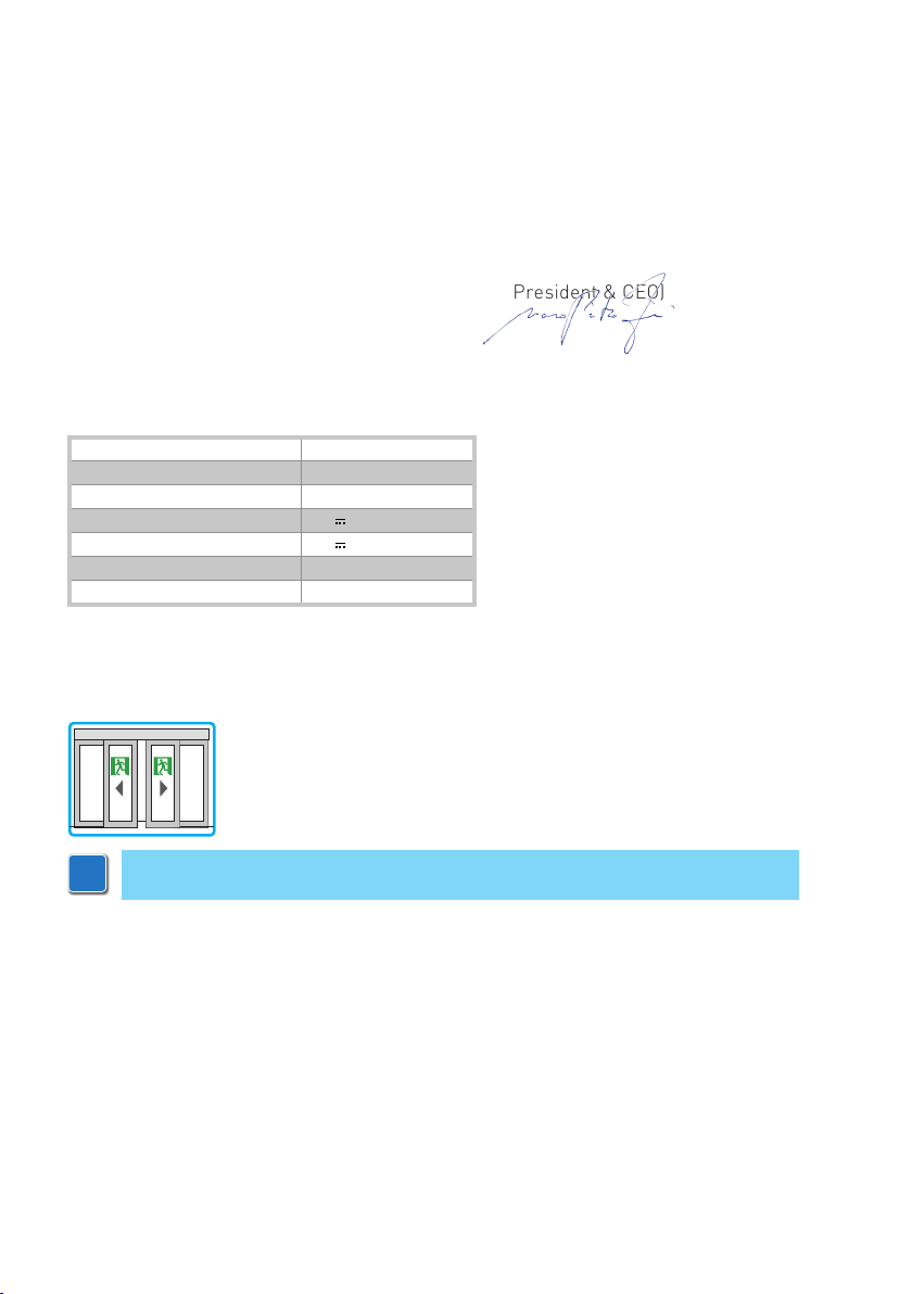
The manufacturer Entrematic Group AB, with headquarters in Lodjursgatan 10, SE-261 44 Landskrona, Sweden declares that the Ditec EL21 control panel complies with the conditions of the
following EC directives:
EMC Directive 2004/108/EC
Low Voltage Directive 2006/95/EC
Land skro na, 01-12-2013 Mar co Z ini
President & CEO)
3. Technical specifications
Ditec EL21
Power supply 230 V~ 50/60 Hz
F1 fuse F1A
Motor output 24 V 5 A
Power supply for accessories 24 V 0.5 A max
Ambient temperature -20 °C - +55 °C
Degree of protection IP20
3.1 Applications
N.B.: The given operating and performance features can only be guaranteed with the
use of DITEC Entrematic accessories and safety devices.
IP1951EN - 2014-10-06
22
Page 5

4. Electrical connections
Before connecting the power supply, make sure the plate data correspond to that of the mains
power supply.
An omnipolar disconnection switch with a contact opening distance of at least 3mm must be
fitted on the mains supply.
Check there is an adequate residual current circuit breaker and overcurrent cutout upstream
of the electrical system.
For the mains power supply, use a H05RN-F 3G1.5 or H05RR-F 3G1.5 type electric cable. Connect it to terminals L (brown), N (blue), (yellow/green) inside the automation.
Secure the cable using a special cable clamp and remove the sheath only where the clamp is.
In the external automation section, the connections to the mains power supply and any other
low voltage wires (230V) must be made on an independent channel separated from the channel of connections to the command and safety devices (SELV = Safety Extra Low Voltage), and
protected against overcurrents and short-circuiting. The channel must penetrate the automation by a few centimetres through a Ø16 mm hole.
Make sure there are no sharp edges that may damage the power supply cable.
Make sure the mains power conductors (230 V) and accessory power conductors (24 V) are
separated.
4.1 Safety functions
The EL21 control panel has the following safety functions:
• force limitation;
• prevention of contact;
The maximum response time of the safety functions is 1.5 s. The reaction time to a faulty safety
function is 1.5 s.
The safety functions comply with the standard and performance level indicated below:
EN ISO 13849-1:2006 Category 2 PL=c
• emergency opening.
The maximum response time of the safety functions is 1.5 s. The reaction time to a faulty safety
function is 1.5 s.
The safety functions comply with the standard and performance level indicated below:
EN ISO 13849-1:2006 Category 2 PL=d
4.2 Electromagnetic emissions
WARNING: in accordance with Directive 2004/108/EC, the supplied ferrites must be
installed as shown on pages 24-25
Pass the cable through the ferrite, make 1 turn and protect it from knocks by using heatshrink sheathing or similar.
The ferrite must be secured to the cable near the terminal boards (approx. 50 mm).
If you need to use several ferrites due to the number of cables involved, a special kit - KEMC2
- is available for this purpose.
IP1951EN - 2014-10-06
23
Page 6
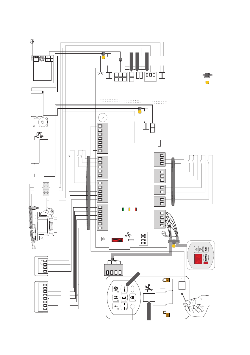
4.3 Electrical connections with Ditec COMER selector
POWER SUPPLY UNIT
MOTOR
DMCS jack
EXTERNAL
VALLOKB BATTERYINTERNAL SENSOR
230 V~
F1=F1,6A
LN
F10A
+
-
black
-
+
red
black
black
grey
grey
CLOSING SAFETY
DEVICE
OPENING SAFETY DEVICE
OPENING SAFETY DEVICE
black
black
black
red
black
black
C
NO
NC
X
ENC
blue
black
-
+
MOT
BUZZER
27 29
ROTARY
1 2AB9
6A 6B 41
OPEN
0 1
3B 8B 41
EXTERNAL
0 1
R+ R- 8A 41
INTERNAL
0 1
POWER
SELECTOR
FUNCTION
SAFETY
SENSOR
POWER
SENSOR
DO NOT USE
BAT
IN
ALARM
red
DO NOT USE
+
SA
black
-
AUX
X
MOT2
black
DO NOT USE
blue
black
-
+
GENERAL
S1 S2
PURPOSE
REMOTE
black
1
G1 G2
1
KO KC
1
AO
1
EO
1
21 22
01
black
BAT
+
+
black
-
LK
+AUX
EL21
FERRITE (1 turn)
X
AUXILIARY OPENING
KEY CLOSE
EMERGENCY OPENING
KEY OPEN
SENSOR
PAS024AMT
24V
01R+ R- 1841 0
blue
red
grey
pink
white/black
yellow/black
brown
green
OPEN
COMER
102122
3
2
1
24
123 4
ON
DO NOT USE
1
OP
KEY
12I1I
4 5 6
2
DO NOT USE
MD1
X
1R
MR
RESET
POWER
PPI
IP1951EN - 2014-10-06
Page 7
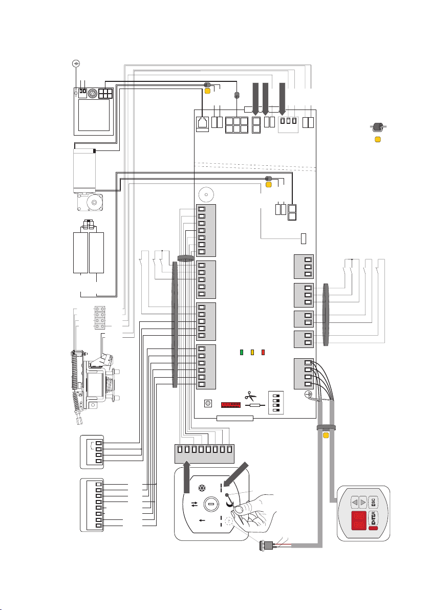
4.4 Electrical connections with Ditec COMKR selector
MOTOR
EXTERNAL
INTERNAL SENSOR
BATTERY
VALLOKB
POWER SUPPLY
230 V~
F1=F1,6A
LN
UNIT
X
black
blue
-
+
ENC
MOT
DO NOT USE
black
black
black
black
DO NOT USE
black
EL21
-
+
1
S1 S2
LK
DO NOT USE
-
+
BAT
AUX
POWER
FERRITE (1 turn)
X
F10A
+
-
black
SENSOR
PAS024AMT
-
+
red
black
black
grey
grey
24V
01R+ R- 18A410
X
BUZZER
27 29
ROTARY
SELECTOR
CLOSING SAFETY DEVICE
OPENING SAFETY DEVICE
OPENING SAFETY DEVICE
black
black
black
red
black
black
C
NO
NC
1 2AB9
6A 6B 41
OPEN
0 1
3B 8B 41
EXTERNAL
0 1
R+ R- 8A 41
INTERNAL
0 1
FUNCTION
SAFETY
SENSOR
POWER
ALARM
SENSOR
OPEN
292827
9BA1 2
blue
red
grey
pink
white/black
yellow/black
brown
green
DO NOT USE
COMKR
DO NOT USE
IN
POWER
red
SA
RESET
blue
+
MOT2
123 4
ON
DMCS jack
black
-
BAT
G1 G2
1
GENERAL
PURPOSE
KO KC
1
AO
1
EO
1
21 22
REMOTE
01
21-red
22-white
+
+AUX
AUXILIARY OPENING
KEY CLOSE
X
EMERGENCY OPENING
KEY OPEN
MD1
IP1951EN - 2014-10-06
25
Page 8
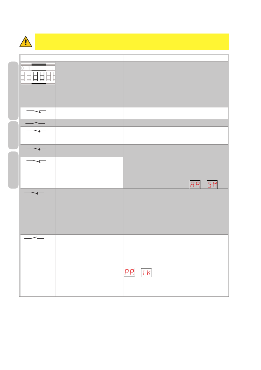
5. Commands
41
0
WARNING: make a jumper for all NC contacts if not in use. The terminals with the
same number are equal.
Command Function Description
01R+ R- 8A
SENSOR
INTERNAL
41 8A NC REVERSAL
1 3B NO OUTER SIDE OPENING Contact closure activates the opening operation.
41 8B NC REVERSAL
SENSOR
EXTERNAL
41 6A NC LH SIDE OPENING
41 6B NC OPENING SAFETY
DEVICE
OPENING SAFETY
1 EO NC EMERGENCY
1 KO NO KEY OPENING Contact closure activates the opening operation.
A 4
INNER SIDE
OPENING
SAFETY CONTACT
SAFETY CONTACT
SAFETY DEVICE
DEVICE - RH SIDE
OPENING
Connect an autocontrolled safety sensor model
PAS024AMT (or equivalent) as described on pages 2425 or in section 10.
N.B.: terminals R+/R- are a current input.
Check on sensor PAS024AMT that the activation output
is set to CURRENT [5].
For further information refer to the PAS0AM24T sensor
installation manual.
Opening the contact triggers a reversal of motion (reopening) during closing.
Opening the contact triggers a reversal of motion (reopening) during closing.
The opening of the contact causes the opening speed
to decrease in the last 500 mm of stroke of the door
wing.
Presence sensors can be connected as well, as described in section 9.
Advanced command management is available with the
MD1 display module. See function → .
Opening the contact activates emergency opening
operation. This command is active in every situation
(also in NIGHT-TIME CLOSURE mode) and has priority over every other command. When the contact has
closed again, the door goes back to working as set by
the COMER or COMKR selector.
N.B.: this command can be combined with an emergency button.
If the door is set to NIGHT-TIME CLOSURE mode,
the KEY OPEN command will carry out the opening
operation and activate door operation in TWO-WAY
mode (or for the time set by the MD1 display module).
→ ).
N.B.: this command can be combined with a key to
allow evening exiting or morning entry through a shop
door set to NIGHT-TIME CLOSURE mode.
IP1951EN - 2014-10-06
26
Page 9
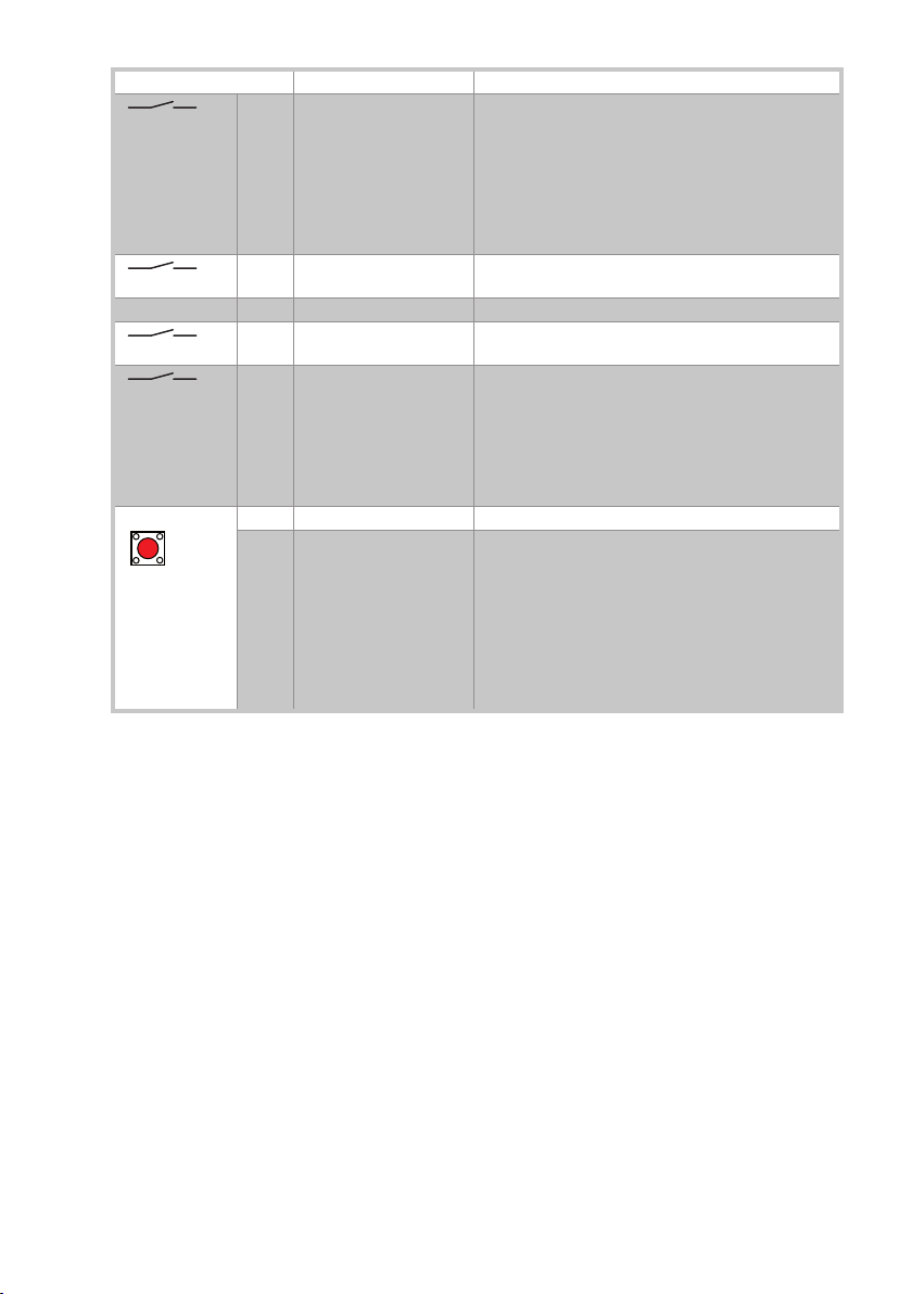
Command Function Description
OPEN
1 KC NO KEY CLOSING The closing operation starts when the contact is closed.
GENERAL PURPOSE Disabling /enabling of COMER function selector switch.
1 G1
G2 GENERAL PURPOSE FUTURE USE
1 S1 NO CONNECTION OF
1 AO NO AUXILIARY
NO
MICROSWITCH
OPENING
NO OPENING Press quickly to activate opening operation.
SETTINGS RESET Keep the OPEN button pressed (for 4 s), until the IN
If the door is set to NIGHT-TIME CLOSURE mode, the
KEY CLOSING command, given after opening with the
1-KO command, will close the door and immediately
restore the NIGHT-TIME CLOSURE mode.
N.B.: this command can be combined with a key to allow
immediate reclosing of a shop door set to NIGHT-TIME
CLOSURE mode.
Make connection, as described on page 24.
Connect block microswitch as described on pages 24-
25.
Contact closure activates the opening operation.
If the operation as escape route is disabled, it will be
re-enabled for 5 minutes (or for the time set by the
display module MD1).
N.B.: This command can be combined with a magnetic
card reader for access to automated teller machines if
the door is set to NIGHT-TIME CLOSURE mode .
LED starts to flash. To confirm the operation, press the
OPEN button again for 2 seconds within 4 seconds.
The SETTINGS RESET deletes all the remote software
settings made using the DMCS software, the MD1 display module and the COMER selector.
N.B.: We recommend carrying out the SETTING RESET
during starting (see section 11), or whenever the COMER selector is replaced with a COMKR selector.
IP1951EN - 2014-10-06
27
Page 10
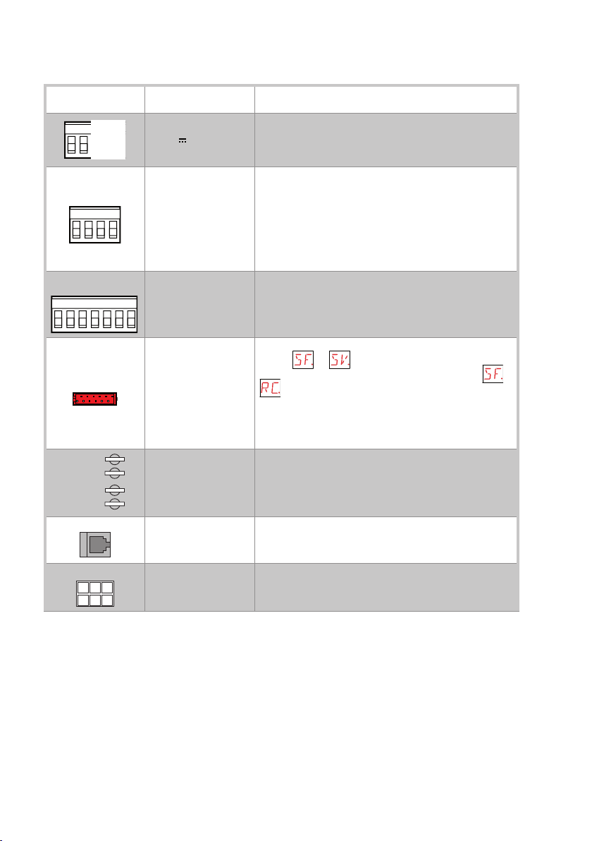
6. Outputs and accessories
41
REMOTE
ROTARY FUNCTION
COM
+
ENC
POWER
Output
01R+ R- 8A
0121
22
SELECTOR
12AB927 29
MOT
-
+
MOT2
-
Value /
Accessories
24 V 0.5 A (max)
COMER
MD1
COMKR
BIXMR2
AL2
Description
Accessories power supply. External accessories power supply output.
N.B.: the maximum absorption of 0.5 A corresponds to the
sum of all terminals 1.
Allows connection of the COMER selector and MD1 display
for distances of up to 50 m.
N.B.: use a data transmission type screened cable.
Connect the shielding to the earthing.
N.B.: If firmware needs updating, connect the DMCS device
to the DMCS JACK on the function selector switch. When the
operation has been completed, disconnect the DMCS device
and perform a POWER RESET.
It allows COMKR selector connection, as described on page
25.
N.B.: connect terminals 21-22 (REMOTE) to the DMCS jack
on the COMKR selector using a data transmission type
shielded cable.
This allows the functioning configurations to be saved using the → function of the MD1 display module.
The saved configurations can be recalled via the →
function of the MD1 display module.
If the co ntrol pane l is replace d, the BIX MR2 stora ge module
being used can be inserted in the new control panel.
WARNING: the storage module must be inserted and removed with the power supply disconnected.
Motor connection.
Connect the double winding motor to the control panel using
the supplied cables as described on pages 24-25.
Encoder connection.
Connect the encoder to the control panel using the supplied
cables as described on pages 24-25.
Power supply unit connection, as described on pages 24-25.
IP1951EN - 2014-10-06
28
Page 11
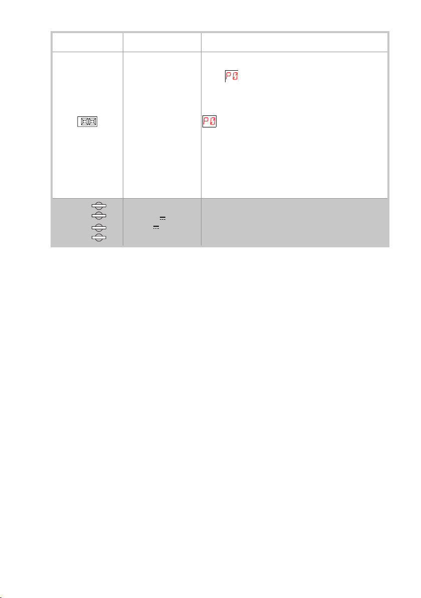
Output
+
LK
AUX
BAT
-
+
-
Value /
Accessories
2 x 12 V / 1.2 Ah
24 V 1 A
24 V 200 mA
Description
Anti-panic battery kit.
With the mains power supply off, with an alarm condition
(alarm appears on the display with 5 acoustic signals),
the automation performs an opening operation at low speed
unless in NIGHT-TIME CLOSURE mode.
In NIGHT-TIME CLOSURE mode, with the mains power supply off, the automation goes into an alarm condition (alarm
appears on the display with 5 acoustic signals) without
performing an opening operation.
To charge the batteries, connect the mains power and the
battery kit at least 30 minutes before starting the system.
WARNING: connect batteries, as described on pages 24 and
25.
to allow charging, the batter y kit must be connected to the
control panel at all times. Per iodically check the ef ficiency
of the battery kit.
Bistable blocking device. Bistable blocking device power
supply output.
WARNING: connect block auxiliary coil to AUX terminals, as
described on pages 24 and 25.
IP1951EN - 2014-10-06
29
Page 12
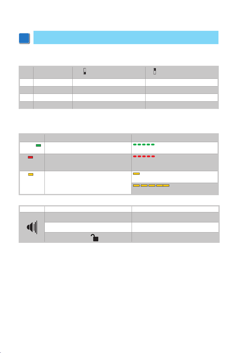
7. Adjustments
i
Make adjustments as explained in the MD1 display module installation manual
7.1 Dip-switches
DIPs Description
DIP1 Block type VALLOKB No block
DIP2 FUTURE USE / /
DIP3 Door wing weight <200 kg >200 kg
DIP4 FUTURE USE / /
OFF
ON
7.2 Signals
LED On Flashing light
POWER Power supply on. Encoder not working or automa-
SA Indicates that at least one of the safety con-
tacts is open.
IN A total or partial opening command or clos-
ing command is received.
BUZZER Event Effect
Escape route test 1 acoustic signal every second
Alarm signalling 5 acoustic signals every minute
COMER selector enabled
tion faulty.
Safety test failure (terminal 41).
The dip s witch or COMKR selector status
changes
SET TINGS RESET in pro-SET TINGS RESET in pro-
gress.
6 acoustic signals every 10 seconds
IP1951EN - 2014-10-06
30
Page 13
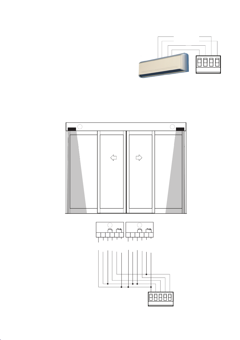
8 Escape route sensor
On sliding doors used in escape routes, the opening on the exit direction shall be controlled by an
autocontrolled safety sensor model PAS024AMT (or
equivalent).
If you use a PAS024AMT sensor, make connections as
indicated on pages 24-25.
Check that the activation output is set to CURRENT [5]
(see PAS024AMT installation manual).
9. Autocontrolled safety sensor
Autocontrolled safety devices can be connected as shown in the figure.
Set DIP10=ON on each PASAT3.
yellow/black
YELLOW/BLACK
WHITE/BLACK
white/black
01R+ R-
INTERNAL
INTERNAL
SENSOR
SENSOR
A
A
24V
-+
12
3456 12
RED
BLUE
GREEN
WHITE
BROWN
B
24V
-+
3 456
RED
BLUE
WHITE
GREEN
ORANGE
BROWN
ORANGE
B
IP1951EN - 2014-10-06
016A 6B 41
OPEN SAFETY
31
Page 14

10. Start-up
i
WARNING: Before performing any type of operation, make sure that the automation
is turned off and the batteries are disconnected.
The operations in point 6 are performed without safety devices.
- Check that connections are correct (make a jumper for all unused NC contacts);
- check the internal safety sensor connection (PAS024AMT);
- check functions COMER or COMKR sensor connection;
- check MD1 display module connection;
- check battery connection;
- turn on the power (connect the mains) and wait 60 s for the initial autoconfiguration and for
automatic execution of the escape route test procedure;
WARNING: the control panel performs an automatic POWER RESET with each start and the
first opening or closing operation is performed at low speed to allow the automatic selflearning of the stop positions (acquisition).
- perform a SETTINGS RESET using the OPEN button as indicated in section 5;
- set the two-way operating mode using the COMER or COMKR selector, as indicated in the instructions for use;
- check that the automation is operating correctly with a series of open commands;
- make the desired operating setting and adjustments using the MD1 display module (as indicated
in the relevant manual);
- connect any accessories and safety devices and check they are working;
WARNING: pass the accessory cable through the ferrite, as shown on pages 24 or 25.
- check that the operating force and contact force between the door wing and the obstacle is lower
than that indicated in the EN 16005 Standard.
- once starting has been completed, the installer shall supply all the information relating to automatic, manual and emergency operating modes of the motorised door and must provide the
user with the operating instructions.
- the sliding door for escape routes built to meet the requirements outlined in this manual complies with the sample inspected by TÜV and is suitable for installation and use in escape routes
in accordance with the EN 16005 standard and German AutSchR guidelines.
- the sliding door for escape routes guarantees full opening (through lateral sliding of the door
wings) in all situations in which there is a power supply failure and in all fault conditions. An
escape route test is performed at least every 24 hours (lasting approximately 10 seconds) to
check that all the components are operating correctly.
N.B.: in the event of servicing or if the control panel is to be replaced, repeat the startup procedure.
IP1951EN - 2014-10-06
32
Page 15
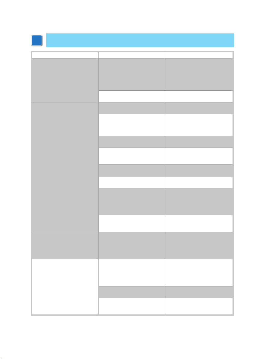
11. Troubleshooting
i
N.B.: refer to the Alarm and fault visualisation section in the DISPL AY module
installation manual.
Problem Possible cause Operation
The automation does not open
and close or does not perfor m the
set operations.
The automation does not open or
close.
The automation opens by itself. The radars are instable or detect
The automation opens/closes
briefly and then stops.
Function selector switch fault. Perform the SE TTINGS RESE T
Function selector switch incorrectly set.
No power.
(POWER ALARM LED of f).
Short circuited accessories.
(POWER ALARM LED of f).
Blown line fuse.
(POWER ALARM LED of f).
The stop contact is open. Check terminal 9 of the control
The automation is locked by bolts
and locks.
Safet y contacts are open.
(SA LED on).
The radars are activated. Make sure the radar is not sub-
The automatic closing does not
work.
moving objects.
Encoder disconnected, false encoder contacts, encoder fault.
(flashing POWER ALARM LED).
Motor leads crossed.
(flashing POWER ALARM LED).
There is a presence of friction. Manually check that the door
using the OPEN button as indicated on page 27.
WARNING: this operation may
cancel previously made remote
adjustments.
Check and correct the function
selector switch settings.
Check the control panel is powered correctly.
Disconnect all accessories from
terminals 0-1 (a voltage of 24V=
must be present) and reconnect
them one at a time.
Replace fuse F1.
panel and the position of the function selector switch (if present).
Check that the door wings move
freely.
Check terminals 6 and 8 of the
control panel.
jected to vibrations and does not
make false readings or check
the presence of moving objects
within its range.
Check jumper 1-2 and the position of the function selector
switch (if present).
Make sure the radar is not subjected to vibrations and does not
make false readings or check
the presence of moving objects
within its range.
Check that the encoder is connected correctly, clean the contacts by connecting and disconnecting the encoder plug on the
contacts, replace encoder.
Check the motor leads.
wings move freely and adjust the
door wing in height by lifting it.
IP1951EN - 2014-10-06
33
Page 16
IP2149EN - 2014-10-06
Entrematic Group AB
Lodjursgatan 10
SE-261 44, Landskrona
Sweden
www.ditecentrematic.com
 Loading...