

Page 1
April 15, 1989
THIS BULLETIN COVERS:
I
. EPS DIAGNOSTICS
.
EPS - THE 7501 MAIN BOARD AND THE 10002 MAIN BOARD
EPS DIAGNOSTICS
A number of
a faulty power supply. The following are the most common problems which could be caused by a faulty power
SUDDIV:
,. ,
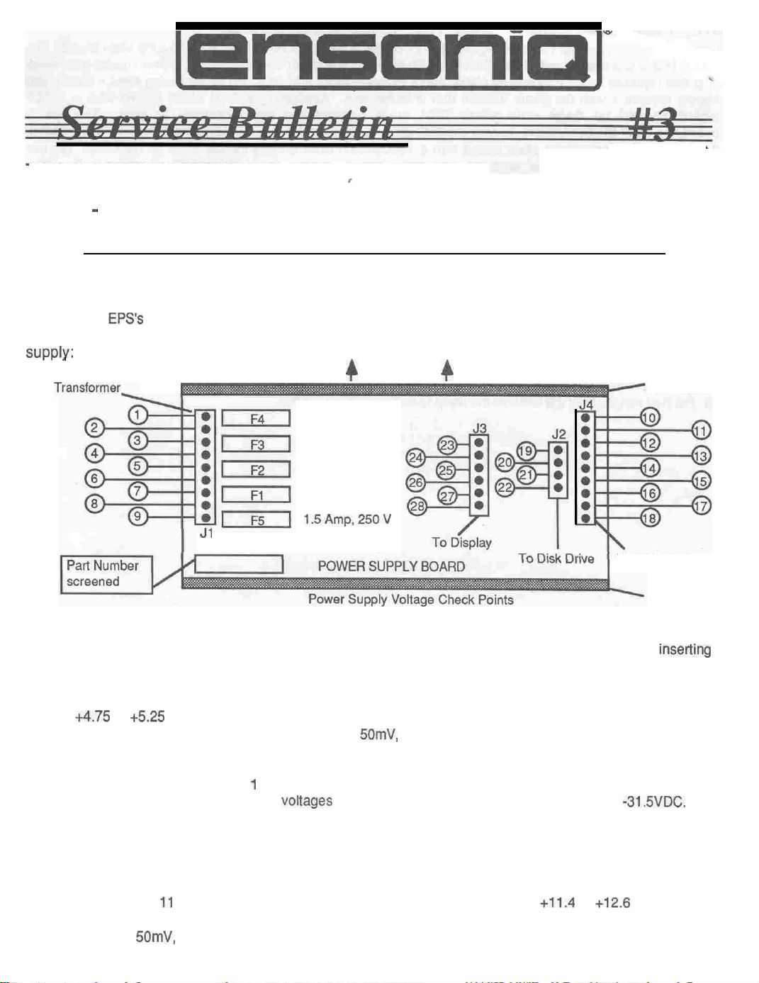
To Transformer-
EPS’s
have been incorrectly diagnosed as having a faulty main board when the real problem was
4
Back
4.0
Amp, 250 V
4.0 Amp, 250 V
of Unit
4
Heat Sink
1.5 Amp,
1.5 Amp,
Jl
1 .
PROBLEM: Hum or buzz in audio output; EPS crashes randomly; or problems develop after
memory expander.
SOLUTION: Check the voltages on the power supply at J4 with the power supply loaded (main board
and display board connected). Using pin 11 as ground, the voltages on pins 14, 16, and 16 (of J4) should
be
+4.75
to
+5.25
VDC. The AC ripple on these pins should be less than 50mV. If the voltages are not
within this range or the AC ripple is greater than
2. PROBLEM: EPS is dead on power up.
SOLUTION: Perform solution I above. If no problem is found, check the voltages on the power supply
at J3.
voltages are not within this range, replace the power supply.
pin 25 (of J3).
3. PROBLEM: EPS has disk drive loading problems.
SOLUTION: Perform solution 1 above. If no problem is found, check the voltages on the power supply
at J2. Using pin 11 of J4 as ground, the voltage on pin 22 (of J2) should be
ripple on this pin should be less than 50mV.
greater than
Using pin 23 as ground, the
It should be -29 to -37.2 VDC. If the voltage is not in this range, replace the power supply,
50mV,
replace the power supply.
1.5Amp.250V
VOltageS
250 V
250 V
To Main Harness
Heat Sink
inserting
50mV,
replace the power supply.
on pins 27 and 28 (of J3) should be -22.7 to -315VDC. If the
If no problem is found, check the voltage at
+11.4
to
+12.6
VDC. The AC
If the voltage is not within this range or the AC ripple is
a
Page 2
THE 7501
Unitswnh &&al
-lWtlN
BOARD AND THE 10002 MAIN BOARD
numbers 16582 or higher (240V- 502603) contain a new version of the EPS Main Board. The
10002 board is a new layout of the 7501 Main Board with: the tower board included: a new square gate array
chip that replaces several individual chips; and a different size RAM chip. When replacing a main board, you
should replace ii with the same version that is in the unit. Replacing a 7501 Maln Board
board should be done only when 7501 maln boards are not
,avallable
to you. The 10002
with
a 10002
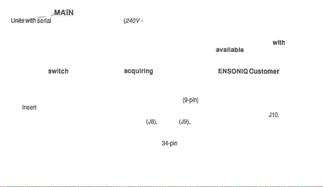
board has all of the connectors (except the disk drive connector, J2) in a different place from the 7501 board.
If you must replace a 7501 Main Board with a 10002 Main Board, three cables must be replaced. D
attempt to switch boards without
acqulrlng
these cables from
ENSONIQ Cbstomer
O
not
Servlce:
Keyboard Cable, Main Board Power Cable (attached lo main harness), and SCSI Cable (if applicable),
1.
Remove the 7501 Main board as described in the EPS Service Manual.
2.
Clip the four wire ties that hold the main board power cable
3.
Insert
the new 10002 Main Board as described in the EPS Service Manual.
4.
Attach the new main board power cable to the power supply at J4 and to the main board at
5.
Reconnect the cables from the display board
6.
Use two wire ties to bundle the new main board power cable out of the way. NOTE: Leave the wheels
(J8),
wheels
(g-pin)
to the main harness.
(J9),
and disk drive (J2).
Discard this cable.
JlO.
cable out of the wire ties.
7.
If applicable, install the new longer SCSI cable (the
34-pin
ribbon cable from the SCSI board to the auxiliary
expansion, connector J6 on the main board).
8. Replace the existing keyboard cable on the keyboard with the new longer keyboard cable.
9.
Re-install the keyboard as described in the EPS Service Manual.
10. For best results, boot the unit with the latest OS. disk (2.35 or higher).
Page 3
March 20, 1991
This Bulletin Covers:
l
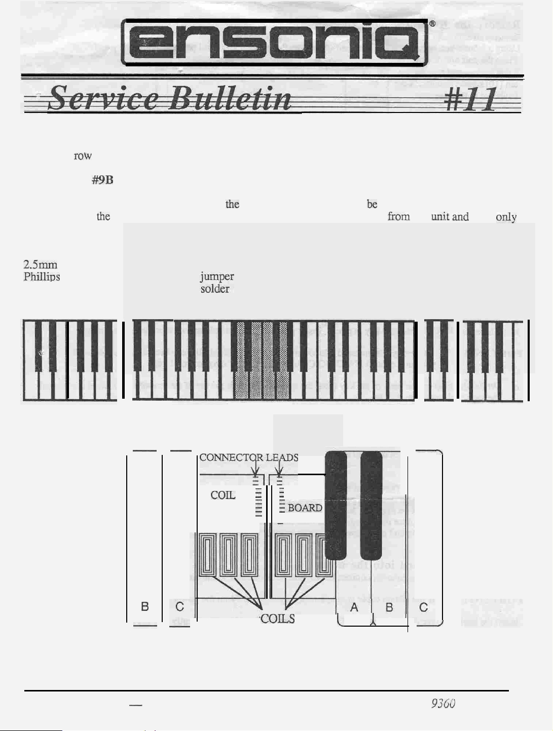
Soldering jumper wires between the two Poly-Key Keyboard Coil Boards that have a twelve-pin
single
not need to be hardwired.) This bulletin should only be done after performing Service
Bulletin
row
connector. (A twenty-pin dual-row connector was used after November 1990 and does
#9B
to ensure that the unit has the latest KPC version and resistors.
To form an absolute connection between
together using
remove six keys from the middle of the keyboard to expose the solder side of the connectors.
Tools Needed:
2.5mm
PhiIlius
soldering iron
hex wrench
screwdriver
the
wires provided. You will need to remove the keyboard
n
I
-
-
the
two coil boards, you
small flat blade screwdriver
zynr
CONNECT(QDS
wires from ENSONIQ
Remove
these six keys
SINGLE-ROW
(12)
COlL :
BOARD
i
q
f
COIL
iBOARD
3
will be hardwiring the coil boards
from
the
uu;t and
then
only
II
,
B
COILS
Service Bulletin #I I - Poly-Key Keyoard Coil
(over)
Boards
I
A
PIN
J
9TGC
CO86 01 -A
Page 4
A. Remove the Keyboard from the unit
;;
3)
Remove
Using a
Place
all
external cables connected to the unit. including the Power cord.
2.5mm
hex wrench, remove the four (4)
the
unit upside
down
on
scr~s
that fasten the control panel and raise
the
panel.
Carefully mm the unit right side op. Raise the
4)
the main board. paying particular attention to the polarity.
Remove the keyboard from the case by gently lifting up
5)
Once the
keyboard cavity.
B . Remove Middle D through
rear
of the keyboard has
cleared the
(
contxol panel
control
(see figure on p. 1)
1)
Place
the
keyboard with the keys up on
2)
Remove
a.
b. Push
3)
Remove
a.
b.
IMPORTANT!
c. While
the
key springs:
Insen a small Phillips screwdriver
down
to
expand the
the springs in a
the
keys to expose the coil boara connecmrs
Just below the key number (near the
There is a clip that holds
lifting up on the back of the key (near
the
keyboard to release
safe
These.
pressure, contact
spring,
place. they
the
clips do not need a lot of pressure to be released.
the
d
hz
spring
key in place.
ENSONlQ
clip.
hole) on
Insert
Customer Service for a replacement key.
C. Solder the connector leads together
1)
Hardwire
a.
the connector leads together
If there are two rows of leads on each
a better
co~ector and does
not need to be
(horizontally).
board.
do not solder them together.
hardwised.
and disconnect
the
front of it while pulling it toward
panel
mounting tabs, the keyboard can be removed
(wnxe Keys nrst):
the
key there is a
a small/thin flat blade
the
spring hole) push
the Z&pin
rectnngular
scmwdriver
If a clip breaks due to
the
top
of
The
keyboard ribbon cable
opening.
into the opening.
the
screwdriver toward
twenty-pin dual-row connector is
the
front of the unit
from the
tco
much
the
f?om
back of
D. Reinstall the keys:
1)
Put the black keys on
2)3)Place the
Place
4)
To reinstall
screwdriver into the spring and push down and out to expand it. Then move the bottom
frame.
front
of the key on fast, then press
the
white keys back on in order. Make
the
first.
They go on where
springs, place the spring
there are
the
sure that
into
its hole on the key (open side up). Insert the
single keystops.
back of the
kejj
down
zm!i! the c!ip
the clip for each key is engaged.
catches and holds it in place.
small/thin
the
spring into
Phillips
the
keyboard
E. Install the Keyboard into the unit
1)
Making note of
IMPORTANT!
2)
Insmt
the keyboard rear fust
rear
of the unit, lowering the
slightly to be sure that the keyboard cable lies flat beneath the keyboard and is not pinched under the keyboard frame.
3)
Tom
the unit upside down on a soft surface and replace
4)
Power up, test the unit, and close
page
2
the
proper polarity, connect the keyboard ribbon cable to the main board.
If the ribbon cable is
into the
front
of
the
mispirmed,
unit at
the front
the
keyboard as needed to clear the control panel mounting tabs. Lift the keys
control panel.
fuses F3 and F4 on
of
the
keyboard cavity. Gently slide the keyboard toward the
the
ten (10) screws
the
power supply will blow.
that secure rhe
keyboard to
the
case.
Service Bulletin #II
Page 5

July 25, 1991
This Bulletin Covers:
The latest information on the Poly-Key
previously contained in Service Bulletins
you will be up to date on current developments. This bulletin completely replaces Service
Bulletins #9B AND #11.
IMPORTANT!
.
If the coil board-to-coil board connector is
six keys as described in Section E). hardwire it together (follow
both foam and foamless keyboards.
.
If the
coil bard-to-coil board connector is a 20-pin dual-row connector (remove the middle
six keys as described in Section E), call ENSONIQ Customer Service for a replacement
keyboard assembly.
Tools Needed:
#0 Phillips screwdriver
small flat blade screwdriver
2.5mm hex wrench
jumper wires from ENSONIQ
Keyboard.
#9B
and #11.
a 12-pin single-row connector (remove the middle
safety glasses
soldering iron and sol&r
scribe (see Section K)
Some information is new and some was
Please take the time to read this bulletin so
this bulletin). This is for
History . . . . . . . . . . . . .
A
D
F
H
K
Service Bulletin #I2 -- Poly-Key Keyboard Coil Boar&
Types of Keyboards, KPC Versions, and Coil Boards . . . . . . .
Troubleshooting a Unit with a Poly-Key Keyboard Problem (flowchart)
Removing the Keyboard from the unit . . . . . . . . . . . . 5
Remove Keys . . . . . . . . . .
Solderthe Connector Leads Together . . . . . . . . . . . . . .
Reinstall
Installing the Keyboard into the unit . . . . . . . . . . . . . .
Checking the KPC O.S. Version .
Keyboard Ribbon Cable Problems . . . . . . . . . . . . . . .
the
Keys
.
Page
2
4
5
6
6
7
PIN 9360 0091 01 -A
Page 6

A. History
Keyboard failures have been caused by two problems.
coil boards is intermittent, it may cause a keyboard calibration failure, random notes to be played,
or ERROR 144.
two coil boards together).
wire harnesses.
While investigating Keyboard Calibration errors, it was found that a break in the interconnection of
the two coil boards can cause a variety of problems.
horizontal plane while the
one pin doesn’t make contact or loses contact briefly, the keyboard might not calibrate, might
freeze up (button presses have no effect), show an ERROR 144, or might start playing random
notes. Hardwiring the two boards together forms an absolute connection.
The
tin
connectors (most commonly used coating/material for connectors) builds up some oxide
over time.
would be horizontally).
ONLY (no movement horizontally at all) and therefore the oxide would not be cleared off.
oxide buildup could cause one or more pins to lose contact over time.
The fix is to make a reliable connection between the two coil boards
Second, a few failures have been caused by faulty ribbon cables and
force
exerted on the connector by playing is in a vertical direction.
This oxide is cleared by a wiping action when the pins are moved in their plane (here it
However, the force on the coil board-to-coil board connector is vertical
First, when the connector between the two
(hardwire
The coil board connectors move in a
If
This
the
This problem was masked by the type of flux that we use (Service Bulletin #9B). This flux
leave some residue and we now clean
example the Keypad/Display connector) or hand solder them into the board
connectors helped temporarily because
reconnecting them broke through the oxide buildup on the connector.
This oxide buildup problem was very difficult to find, because shipping a unit from a customer to
the factory could cause the coil board-to-coil board connector to shift enough to break through the.
oxide so that the unit would work fine when it reached the factory.
keyboard from the unit would shift
making contact.
or have a calibration error.
In the investigation of the keyboard failures, it was also found that
the design of the
terms of heat dissipation and clock generation.
sufficient for many keyboards.
board connector.
assembly as it contains information specific to its particular coil boards and keys in its memory.
Other small things were found and corrected as well but the main cause of failure is
to-coil board connector breaking contact.
the keyboard software more reliable, but does not correct the basic problem Changing two
resistor
therefore the resistors are no longer included in the KPC EPROM Update Kit
values
Losing contact on just one pin, even briefly, can cause a unit to lock up (freeze)
KPC
board
Remember that a KPC board can only be replaced with the whole keyboard
(described in Service Bulletin
Changes made to the KPC board make the design more robust in
all
connectors that hang over the edge of the board
Cleaning the
the
wiping action of separating the coil boards and then
Sometimes removing the
the
connector and break through the oxide so that all pins were
there
were some weaknesses in
However, just updating the KPC only is not
The main failure on keyboards is caused by the coil board-to-coil
the
Changes were made to the KPC O.S. EPROM to make
#9B)
helped but does not correct the basic problem,
does
(for
coil board-
All new units from the factory will have the KPC board changes and the coil boards hardwired
together until newly designed coil boards am in production.
for repair will also have this done as a routine part of the service.
page 2
Any units that come into the factory
Service Bulletin #I2
Page 7

B. Types of Keyboards
As you may or may not be aware, there are two types of Poly-Key keyboards: ones with foam
pads on the under sides of the keys and foamless (ones without the foam pads). We currently
manufacture foamless keyboards with coil boards that have reference coils.
Types of WC Versions
The
Each type of Poly-Key keyboard uses a different KPC O.S. version.
versions are shown below.
current KPC O.S.
KPC version
150
203
227
233
The KPC O.S. version is typed on
KPC board is the small circuit board (3.75’: x 4.25”) located on the underside of the keyboard
assembly.
Types of Coil Boards
There are
different
removed from the unit, the reference coil(s) may be seen on the top edge of the coil board below
the lowest key (the left side of the keyboard, see below).
key (see Section E) to get a better view of the coil board
See Section J for information on how to check the KPC O.S.
two types of foamless keyboards:
row than the other coils) and ones without reference coil(s).
Keyboard and Coil Boards
white foam pads on the undersides of the keys
grey foam pads on the undersides of the
foamless -no reference coil
foamless -with reference coil
the
white label on
ones with a reference coil(s) (extra coil(s) in a
Coil Board-
to-Coil Board KPC Version
-
12-pin
._I_-
the
EPROM (U2) on the KPC board.
If
you wish, you may remove the lowest
Current
227
single-row
keys
With the keyboard assembly
Comments
We used more than one
Coil board part number for
this version KPC 227. The
only
a foamless keyboard with
no reference coil.
The
absolute reference is
Service Bulletin
#I2
12-pin
single-row
233
You may use
number as a reference if
you have dismantled the
keyboard.
Call
ENSONIQ for a
replacement keyboard.
You may use the part number
as a reference if you have
dismantled the keyboard.
the
part
page
3
Page 8

C. Troubleshooting a Unit with a Poly-Key Keyboard Problem:
keys
from
the keyboard
(see Section
E).
Hardwire
connector together (see Section
the coil board-to-coil board
No
Make sure
EPROM is 233 or higher
(see Section
that the KPC
J).
F).
KPC
EPROM is 203
I
Page 4
Figure 2
Keyboard Problem
-
Service Bulletin
#I2
Page 9

D. Removing the Keyboard from the unit
Remove all cables connected to the unit, including the Power cable.
1)
Using a 2.5mm hex wrench, remove the four (4) screws that fasten the control panel and raise
2)
the panel.
Place the unit upside
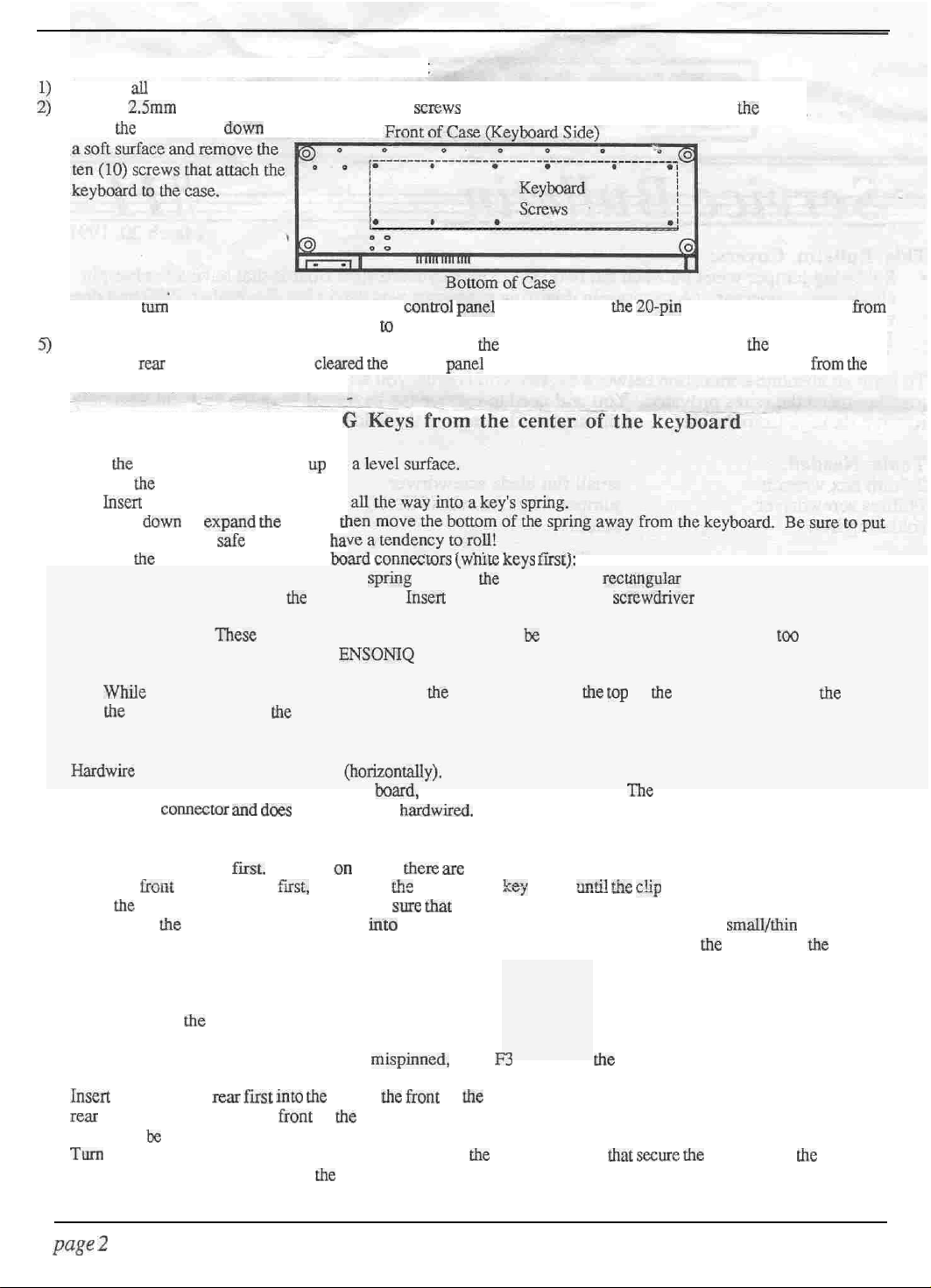
3)
down on a soft surface
and remove the ten (10)
screws that attach the
keyboard to the case.
Figure 3 -Bottom of
Carefully turn the unit tight side up. Raise the control panel and disconnect the
4)
Case
20-pin
keyboard ribbon cable from the main board (using a scribe or similar tool, see Section K),
paying particular attention to the Polarity.
Remove the keyboard from the case by gently lifting up the front of it while pulling it toward
5)
the front of the unit.
Once
the rear of the keyboard has cleared
the
control panel mounting
tabs, the keyboard can be removed from the keyboard cavity.
E. Remove Middle D through G Keys from the center of the keyboard
these six keys
Place the keyboard with the keys up on a level surface.
Remove the key springs:
a. Insert a small Phillips screwdriver all the way into a key’s spring at the tear of the key.
b. Push down to expand the spring, then move the bottom of the spring away from the
keyboard.
Remove the keys to expose the coil board connectors (white keys first):
a. Just below the key number (near the spring hole) on the key there is a rectangular opening.
b. There is a clip that holds the key in place.
opening.
Be sure to put the springs in a safe place, they have a tendency to roll!
Insert a small/thin
flat blade screwdriver into the
IMPORTANT!
These clips do not need much pressure to be released If a clip breaks due to
too much pressure, contact
ENSONIQ
Customer Service for a replacement key.
c. While lifting up on the back of the key (near the spring hole) push the top of the
screwdriver toward the back of the keyboard to release the clip.
d. Remove the white keys first then the black keys.
We suggest keeping the keys in order to
make them easier to put back on.
Service Bulletin
#I2
page 5
Page 10

With the middle D through G keys removed from the center of the keyboard:
B
C
Figure 5- 12-pin coil board-to-coil
board
C
connector
F. Solder the Connector Leads Together
Using
the
jumper
IMPORTANT!
wires
provided, hardwire the connector leads together (horizontally).
If
there
are two rows
the connector is a twenty-pin dual-row, contact ENSONIQ Customer Service
for a replacement keyboard.
of leads on each board, do not solder them together
G. Reinstall the Keys
Put the black keys on first They go on where there are single keystops.
1)
Place the front of the key on first sliding the slot in the front of the key over the keystop on the
2)
keyboard frame, then press the back of the key down until the clip catches and holds it in
place.
Place the white keys back on in order. Make sure that the clip for each key is engaged
3)
To reinstall the springs, place the spring into its hole on the key (open side up). Insert the
4)
small/thin Phillips screwdriver into the spring and push down and out to expand it.
move the bottom the spring into the keyboard frame and remove the screwdriver from the
spring to lock it in place.
If
Then
H. Installing the Keyboard into the unit
Making note of the proper polarity, connect the keyboard ribbon cable to the main board
1)
IMPORTANT!
Insert the keyboard rear first into the unit at the front of the keyboard cavity. Gently slide
2)
keyboard toward the rear of the unit, lowering the front of the keyboard as needed to clear the
control panel mounting tabs. Lift the keys slightly to be sure that the keyboard cable (and disk
drive cable when present) lies flat beneath the keyboard and is not pinched under the keyboard
frame.
Turn the unit upside down on a soft surface and replace the ten (10) screws that secure the
3)
keyboard to the case.
Power up, test the unit, and close the control panel.
4)
page
6
If ribbon cable is mispinned, fuses F3 and F4 on the power supply will
Service Bulletin
the
#I2
Page 11

J. Checking the KPC O.S. Version Number
SD-l,
While holding down Presets, press
VFXSD
and VFX
Master.
The display shows ENSONIQ
-
SOFTWARE - ROM V X.XX KPC YYY. X.XX denotes the main operating system and YYY
indicates the KPC O.S. version. See note in Section K for VFXSD keyboard ribbon
cable problems.
EPS-16 PLUS and EPS
Press
Command,
right arrow button until the display shows
then
Env1. The display shows NO COMMANDS ON PAGE. Press the
SOFTWARE
INFORMATION. Press Enter.Yes
until the display shows KPC VERSION YYY.
K. Keyboard Ribbon Cable Problems
We have found that some units have developed further problems once a keyboard is installed
has been a result of improper handling of the keyboard ribbon cable. We suggest removing the
cable connector using the angled end of a scribe (see below).
Figure 6 -
Scribe
These can be found in the following catalogs:
l
Techno-Tool catalog 38, page 204, part number 400PR144
l
Newark catalog 110, page 1024, part number 76-1510
This
Note for
Be sum to route the keyboard ribbon cable around the square
VFXSD
Only:
68-pin
gate array on the main board.
After you insert the keyboard into place, lift the keys slightly and visually check to make sure that
the cable is not over
Bottom view of ferrite
the
gate array.
New
Keyboard Cable
Routing for the VFX-SD
A misplaced or crimped cable can result in what seems to be a keypad/display problem because
keypad/display information is passed
through
the KPC board to the main board.
You may call
ENSONIQ Customer Service for a new cable with these folds.
Service Bulletin #I2
page 7
 Loading...