

Page 1

P r o f e s s i o n a l 2 4 - B i t E f f e c t s P r o c e s s o r
R e f e r e n c e M a n u a l
V e r s i o n 1 . 1 0
Page 2

D P / P r o R e f e r e n c e M a n u a l :
Written, designed, and illustrated by: Robby Berman and Jonathan Coulton
Special Thanks: Ray Legnini and Bryan Pape
Please record the following information:
Your Authorized ENSONIQ Dealer:___________________________ Phone:_______________
Your Dealer Sales Representative:_________________________________________________
Serial Number of Unit:___________________________ Date of Purchase:_________________
Your Authorized ENSONIQ Dealer is your primary source for service and support. The above information will be
helpful in communicating with your Authorized ENSONIQ Dealer, and provide necessary information should you
need to contact ENSONIQ Customer Service. If you have any questions concerning the use of this unit, please
contact your Authorized ENSONIQ Dealer first. For additional technical support, or to find the name of the nearest
Authorized ENSONIQ Repair Station, call ENSONIQ Customer Service at (610) 647-3930 Monday through Friday
9:30 AM to 12:15 PM and 1:15 PM to 6:30 PM Eastern Time. Between 1:15 PM and 5:00 PM we experience our
heaviest call load. During these times, there may be delays in answering your call.
This manual is copyrighted and all rights are reserved by ENSONIQ Corp. This document may not, in whole or in
part, be copied, photocopied, reproduced, translated, or reduced to any electronic medium or machine readable
form without prior written consent from ENSONIQ Corp. The DP/Pro software/firmware is copyrighted and all
rights are reserved by ENSONIQ Corp.
Although every effort has been made to ensure the accuracy of the text and illustrations in this manual, no
guarantee is made or implied in this regard.
IMPORTANT:
Note: This equipment has been designed and found to comply with the limits for a Class B digital device, pursuant
to Part 15 of the FCC rules. These limits are designed to provide reasonable protection against harmful interference
in a residential installation. This equipment generates, uses and can radiate radio frequency energy and, if not
installed and used in accordance with the instructions, may cause harmful interference to radio communications.
However, there is no guarantee that interference will not occur in a particular installation. If this equipment does
cause harmful interference to radio or television reception, which can be determined by turning the equipment off
and on, the user is encouraged to try to correct the interference by one or more of the following measures:
* Reorient or relocate the receiving antenna.
* Increase the separation between the equipment and receiver.
* Connect the equipment into an outlet on a circuit different from that to which the receiver is connected.
* Consult the dealer or an experienced radio/TV technician for help.
Changes or modifications to the product not expressly approved by ENSONIQ could void the user’s FCC authority
to operate the equipment.
In order to fulfill warranty requirements, your DP/Pro should be serviced only by an Authorized ENSONIQ Repair
Station. The ENSONIQ serial number label must appear on the outside of the unit, or the ENSONIQ warranty is
void.
Copyright © 1997
ENSONIQ® Corp
155 Great Valley Parkway
Box 3035
Malvern, PA 19355-0735
USA
World Wide Web—http://www.ensoniq.com
Printed in U.S.A.
All Rights Reserved
• ENSONIQ and DP/Pro are trademarks of ENSONIQ Corp.
Part # 9310020501 Model # MM-142
Page 3
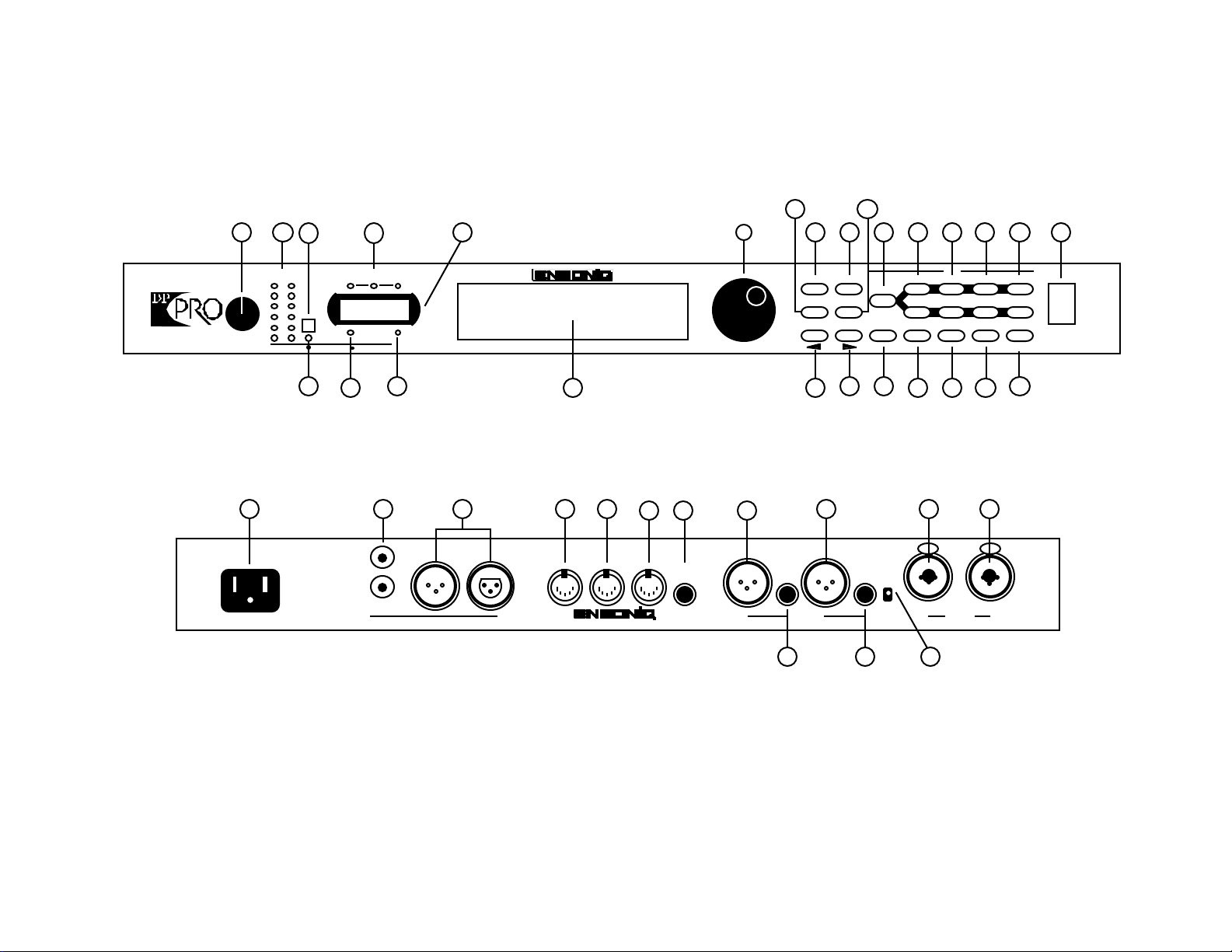
DP/Pro Front Panel View
Headroom
0
3
6
12
20
Input Level
(Stereo)
30
L R
Meter
Function
Analog Input
4
DP/Pro Rear Panel View
28
50/60Hz
100 -240VAC~
WARNING!
To reduce the risk of
fire or electric shock do
not expose this product
to rain or moisture.
48k 44.1k
32k
MIDI In Digital In
Digital Output
29
In
Out
Sample
Rate
65
In Out
AES/EBUS/PDIF
professional 24 bit effects processor
987
31 32 3330 34 35 37 40 41
Digital Audio
MIDI InMIDI OutMIDI Thru Foot Sw
1 & 2
DP/Pro
Value
10
36 38
11
14
1312
Effect
Select
Find
Tweak Tap
Previous Next
Page
Routing
Edit
Algo A Params A Mod A Bypass A
Algo B Params B Mod B Bypass B
Compare SaveEnter Cancel System
15 16 22 23 24 25 26
push
RL
+4 dBu
Outputs Inputs
-10 dBv
I/O Level
L
39
21321 20191817
MIDI
push
R
TRS Inputs & Outputs
are Bal/Unbal
27
Power
Page 4

Front and Rear Panel Key
1. Input Level Knob—set analog input level to the DP/Pro. 22. Enter button—executes various DP/Pro operations.
2. Headroom LEDs—show analog input level to, or digital 23. Compare button—toggles between edited and last-saved
output level from, the DP/Pro version of currently selected effect.
3. Meter Function switch—sets behavior of Headroom LEDs. 24. Cancel button—undoes last operation.
4. Meter Function LED—shows current meter function. 25. Save button—intitiates process of saving effects to memory.
5. Sample Rate LEDs—show the DP/Pro current sample rate. 26. System/MIDI button—provides access to global parameters.
6. Auxiliary display—shows effect, algo and parameter numbers. 27. Power switch—turns the DP/Pro on and off.
7. MIDI In LED—lights to show incoming MIDI data. 28. AC Line jack—connects power cord to DP/Pro.
8. Digital In LED—lights to show presence of digital sync. 29. S/PDIF Input and Output jacks—connects DP/Pro to an S/PDIF
9. Main DP/Pro display digital device when a DI-Pro Digital I/O board is installed.
10. Value knob—is used to select effects, algos and adjust 30. AES/EBU Input and Output jacks—connects DP/Pro to an AES/EBU
parameters. digital device when a DI-Pro Digital I/O board is installed.
11. Tweak button—provides access to Tweak parameters and 31. MIDI In jack—receives MIDI data.
virtual Tweak knobs. 32. MIDI Out jack—transmits MIDI data from the DP/Pro.
12. Select Effect button—accesses the list of effects currently in 33. MIDI Thru jack—passes received MIDI data out from the DP/Pro.
the DP/Pro’s internal memory; repeated presses moves 34. Foot SW 1 & 2 jack—connects a dual foot switch to the DP/Pro.
between effect banks. 35. Left XLR Analog Output jack—sends analog audio from the DP/Pro’s
13. Find Effect button—accesses Effect Finder. left stereo bus.
14. Tap button—can be tapped to set the DP/Pro’s system tempo 36. Left 1/4” Analog Output jack—sends analog audio from the DP/Pro’s
for synchronized effects. left stereo bus.
15. Previous Page button—scrolls the DP/Pro’s display back 37. Right XLR Analog Output jack—sends analog audio from the
through parameters and moves cursor during some DP/Pro’s right stereo bus.
operations. 38. Right 1/4” Analog Output jack—sends analog audio from the
16. Next Page button—scrolls the DP/Pro’s display forward DP/Pro’s right stereo bus.
through successive parameters and moves cursor during some 40. Combination 1/4” and XLR Left Input jack—receives analog audio
operations. to be sent into the DP/Pro’s left stereo bus.
17. Routing button—provides access to signal-flow settings, and 41. Combination 1/4” and XLR Right Input jack—receives analog audio
to copy/swap functions. to be sent into the DP/Pro’s right stereo bus.
18. Algo A and Algo B buttons—intitiates selection of algorithms
and/or algorithm variations for ESP-A and ESP-B.
19. Params A and Params B buttons—provides access to mixing,
algorithm and Tweak parameter settings for ESP-A and ESP-B.
20. Mod A and Mod B buttons—provides access to real-time
modulation parameters for ESP-A and ESP-B.
21. Bypass A and Bypass B buttons—bypasses ESP-A and/or ESP-B.
Page 5

Table of Contents
Reference Manual Table of Contents
1—Introduction ..............................................................................1
Welcome.................................................................................................................... 1
Parameters, Values and Pages ........................................................................................ 1
Navigating the DP/Pro.................................................................................................. 1
LEDs.............................................................................................................................................................................2
A Note About Read-Only Displays...................................................................................................................2
The DP/Pro Architecture............................................................................................... 3
Effects...........................................................................................................................................................................3
Effect Finder....................................................................................................................................................4
The DP/Pro’s Two ESP2 Processor Chips......................................................................................................4
The Contents of ESP-A and ESP-B..........................................................................................................5
Fast Editing of Parameters.........................................................................................................................5
Bypassing ESP-A and ESP-B.....................................................................................................................5
Copying and Swapping Algorithms......................................................................................................5
Routing........................................................................................................................................................................6
Real-Time Effect Modulation...............................................................................................................................6
The Virtual Tweak Knobs..........................................................................................................................6
The Mod LFOs...............................................................................................................................................6
Synchronizing Effects to a Tempo.....................................................................................................................7
The DP/Pro and MIDI...........................................................................................................................................7
Defining your DP/Pro Workspace....................................................................................................................7
Important: Two Final Concepts..........................................................................................................................7
Downloading and Installing.....................................................................................................................7
Saving................................................................................................................................................................8
Available Options for the DP/Pro.................................................................................... 8
Installing the DP/Pro....................................................................................................8
Powering Up the First Time.................................................................................................................................8
Powering up the DP/Pro in a MIDI Configuration.........................................................................9
Polarization and Grounding.....................................................................................................................9
AC Line Conditioning.................................................................................................................................9
Rack Mounting Guidelines........................................................................................................................10
Temperature Guidelines.............................................................................................................................10
Setting Analog Input Levels........................................................................................... 10
Troubleshooting .......................................................................................................... 11
Battery Replacement...............................................................................................................................................11
Reinitializing the DP/Pro.....................................................................................................................................11
To Reinitialize the DP/Pro........................................................................................................................11
2—System/MIDI Parameters...........................................................13
What Are the Global System and MIDI Parameters?........................................................... 13
The Numbering of the System/MIDI Parameters.......................................................................................13
Selecting the Type of Audio to be Processed..................................................................... 14
Establishing the DP/Pro’s Sample Rate............................................................................14
Global MIDI Settings................................................................................................... 15
Setting Up a Reference for Time-Based Effects.................................................................20
Creating Your Own App Category for Effect Finder........................................................... 22
Grouping Effects for Easy Selection................................................................................ 23
Designating Real-Time Controllers ................................................................................. 25
Setting Up Foot Switch Controls..................................................................................... 26
Using the Tweak Knobs with MIDI Controllers................................................................. 28
MIDI Bypassing of the ESPs.......................................................................................... 28
Determining What Happens When You Bypass an ESP....................................................... 29
Enabling/Disabling Status Messages................................................................................ 30
Protecting Effects from Accidental Erasure....................................................................... 31
Setting What Happens When You Turn On the DP/Pro.......................................................31
Page 6

Table of Contents
Automatic Installation of Effects and Algorithms............................................................... 31
Setting Gain-Reduction Metering ................................................................................... 32
Processing a Single Mono Audio Signal........................................................................... 32
Setting the Global Wet/Dry Mix..................................................................................... 33
Personalizing EQ Low Frequency and High Gain Limits..................................................... 33
Showing or Hiding Unused Effect Memory Locations........................................................ 34
Viewing the DP/Pro’s Operating System Version .............................................................. 35
3—Selecting and Finding Effects ..................................................... 37
Selecting Effects ......................................................................................................... 37
The Effect-Selection Displays..............................................................................................................................37
Selecting Effects from the DP/Pro’s Front Panel.........................................................................................38
Automatic Installation of Effects........................................................................................................................38
Selecting Effects Via MIDI....................................................................................................................................38
Finding Effects ........................................................................................................... 39
Effect Finder..............................................................................................................................................................39
The Effect Finder Criteria.....................................................................................................................................39
The “All” Setting for an Effect Finder Criterion................................................................................39
The Routing Criterion.................................................................................................................................39
The FX Criterion...........................................................................................................................................39
The App Criterion........................................................................................................................................40
The Effect Finder Display.....................................................................................................................................40
Performing a Find...................................................................................................................................................40
The Results of a Find...................................................................................................................................41
4—Signal Routing........................................................................... 43
Choosing a Signal Path................................................................................................. 43
Processing a Single Mono Audio Source.............................................................................................45
The Routing Display..............................................................................................................................................45
Selecting a Routing.................................................................................................................................................46
5—Selecting Algorithms and Variations........................................... 47
Choosing New Algorithms and Variations........................................................................ 47
The DP/Pro Algorithms.......................................................................................................................................47
Variations...................................................................................................................................................................48
The Special *User Variation*....................................................................................................................48
The Algorithm-and Variation Selection Displays........................................................................................48
The Selection of Algorithms and Variations..................................................................................................49
6—Editing Algorithms.................................................................... 51
The Algo Params Display ............................................................................................. 51
Editing Algorithm Parameter Settings.............................................................................. 51
A Note About
Mix parameters.............................................................................................................................................52
Shared LFO Waveshapes.............................................................................................. 52
The DP/Pro Algorithm Parameters.................................................................................. 53
No Effect.....................................................................................................................................................................53
Mastering Limiter....................................................................................................................................................53
Compressor/Limiter..............................................................................................................................................54
Compressor...............................................................................................................................................................55
Servo Limiter.............................................................................................................................................................56
3-Band Comp/Lim.................................................................................................................................................57
Expander....................................................................................................................................................................58
Stereo Gate.................................................................................................................................................................59
Dual-Mono Gate......................................................................................................................................................60
De-Esser......................................................................................................................................................................61
Stereo Synthesizer...................................................................................................................................................62
Stereo Re-Imager.....................................................................................................................................................62
Variable-Tap Delay.................................................................................................................................................63
Spatial Delays...........................................................................................................................................................64
Page 7

Table of Contents
Ping-Pong Delay......................................................................................................................................................66
Stereo Delay...............................................................................................................................................................67
Loop Recorder...........................................................................................................................................................68
Expert Reverb............................................................................................................................................................69
Expert Reverb 2........................................................................................................................................................70
Reflection Modeler..................................................................................................................................................72
Small Ambience 1....................................................................................................................................................73
Small Ambience 2....................................................................................................................................................74
Non-Lin Reverb 1.....................................................................................................................................................75
Non-Lin Reverb 2.....................................................................................................................................................76
Multi-Pitch Shift.......................................................................................................................................................77
Multi-Chorus.............................................................................................................................................................79
Flanger.........................................................................................................................................................................81
Phaser...........................................................................................................................................................................82
Tremolo.......................................................................................................................................................................84
Panner..........................................................................................................................................................................85
Chatter Box.................................................................................................................................................................86
Rotary Speaker..........................................................................................................................................................87
Tunable Speaker.......................................................................................................................................................88
Parametric EQ...........................................................................................................................................................89
Octave EQ...................................................................................................................................................................90
Delay+Chorus...........................................................................................................................................................91
Delay+Flanger...........................................................................................................................................................92
Delay+Phaser............................................................................................................................................................93
Distortion+Chorus...................................................................................................................................................94
Distortion+Flanger..................................................................................................................................................95
Distortion+Phaser....................................................................................................................................................96
Signal Generator.......................................................................................................................................................97
7—Copying and Swapping Algorithms............................................. 99
Using the Copy/Swap Tools........................................................................................... 99
The Copy/Swap Display......................................................................................................................................99
Performing a Copy/Swap Procedure...............................................................................................................99
Moving Algorithms Between Effects Using AlgoMover................................................................100
8—Mixing.......................................................................................101
The ESP-A and ESP-B Mixer Parameters.........................................................................101
The Mixer Params Display...................................................................................................................................101
Editing Mixer Parameter Settings......................................................................................................................102
Setting an ESP’s Input Level................................................................................................................................102
Setting an ESP’s Stereo Input Balance..............................................................................................................102
Setting the Amount of Signal Fed Back to ESP-A from ESP-B................................................................103
Setting the Stereo Balance of Signal Fed Back to ESP-A from ESP-B....................................................103
Setting an ESP’s Output Level............................................................................................................................104
Setting an ESP’s Wet/Dry Output Balance....................................................................................................104
9—Tweak Parameters.....................................................................107
The Tweak Parameter Solution....................................................................................... 107
Designating Tweak Parameters....................................................................................... 107
The Set Tweak Params Display..........................................................................................................................107
Setting Up a Tweak Parameter...........................................................................................................................108
Accessing and Adjusting Tweak Parameters .....................................................................108
The Tweak Display..................................................................................................................................................108
Tweaking a Tweak Parameter.............................................................................................................................109
10—Effect Modulation ....................................................................111
Real-Time Effect Modulation......................................................................................... 111
Overview of Setting Up Real-Time Modulation................................................................. 111
The Modulation Displays......................................................................................................................................112
Selecting a Modulator................................................................................................... 112
Page 8

Table of Contents
Creating a Modulation Reception Window....................................................................... 113
Setting Up the Interpretation of Modulator Values............................................................. 113
Choosing a Parameter to be Modulated............................................................................ 114
Choosing a Modulation Method ..................................................................................... 114
Methods and Shared Destination Parameters....................................................................................114
Setting a Modulation Range........................................................................................... 115
Setting an Additive Modulation Range...........................................................................................................115
Setting an Absolute Modulation Range..........................................................................................................116
Getting to Know the DP/Pro Modulators.......................................................................... 116
Overview of the DP/Pro’s Virtual Tweak Knobs........................................................................................116
Naming an Effect’s Tweak Knobs.....................................................................................................................116
Activating a Tweak Knob.....................................................................................................................................117
MIDI and the Tweak Knobs.....................................................................................................................117
Overview of the Mod LFOs.................................................................................................................................118
Setting the Mod LFO’s Wave Shape.................................................................................................................118
Setting a Mod LFO’s Speed..................................................................................................................................119
Determining the Phase of Synchronized LFOs.............................................................................................119
11—Saving Effects.......................................................................... 121
Where Effects are Saved............................................................................................... 121
Saving an Effect to the DP/Pro’s Memory........................................................................ 121
The Saving Displays....................................................................................................122
The Location Selection Display..........................................................................................................................122
The Effect-Naming Display.................................................................................................................................122
The Effect Finder FX Type Selector Display..................................................................................................122
The Effect Finder App Type Selector Display...............................................................................................123
The “Check Old Effect?” Display......................................................................................................................123
The “Replace Old Effect?” Display...................................................................................................................124
12—Supplemental Information........................................................ 125
DP/Pro Bank 2 ROM Effects List................................................................................... 125
DP/Pro Real-Time Modulators List................................................................................. 130
DP/Pro MIDI Implementation........................................................................................ 130
MIDI Implementation Chart...............................................................................................................................131
Converting Mono Foot Switches for Use with the DP/Pro ................................................... 132
Replace the Mono Foot Switch Plug with a Stereo Plug...........................................................................132
Build a Box to Merge Two Mono Foot Switches into One Stereo Jack.................................................133
About Ground Loops ................................................................................................... 134
Modifying Cables to Eliminate Input Ground Loops................................................................................134
Need More Help?........................................................................................................ 136
13—Glossary.................................................................................. 137
Index....................................................................................... 142
Page 9
1—Introduction
Effect
We lc om e
Congratulations on your purchase of the ENSONIQ DP/Pro Professional 24-bit Effects Processor. The
DP/Pro Reference Manual provides descriptions of all of the DP/Pro’s many features, and provides
tips for unlocking the product’s tremendous sonic potential.
Tip: Be sure to check out ENSONIQ’s World Wide Web home page at
<http://www.ensoniq.com> from time to time for the latest info on the DP/Pro and other
ENSONIQ products.
P ar am e t e r s, Value s and Page s
There are three basic terms that underlie every DP/Pro activity, and which must be understood. They
are:
• Parameter—A parameter is any one of the DP/Pro’s programmable attributes.
• Value—A value is a parameter’s setting.
• Page—The DP/Pro’s front-panel buttons provide access to a great many parameters, often
presented one after another on sequentially arranged displays. Each display is called a “page.”
1—Introduction
Tip: A parameter is described by the button with which it’s associated. For example, if a
parameter is referred as a “System/MIDI parameter,” you’ll know that it’s one of the group of
parameters accessed by pressing the System/MIDI button.
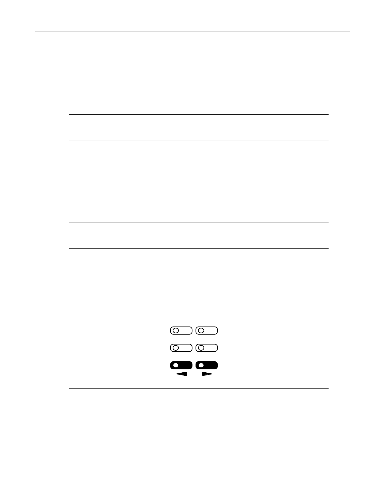
N avigat ing t he DP /P r o
It’s simple to navigate the DP/Pro’s pages and perform its operations once you understand the frontpanel tools central to so many of its activities:
• The Next and Previous Page buttons allow you to move forward or back, and across, the
DP/Pro’s pages.
Tip: The Next and Previous Page buttons, when held down, will scroll through multiple
pages.
Select
Tweak Tap
Previous Next
Find
Page
ENSONIQ DP/Pro Reference Manual 1
Page 10
1—Introduction
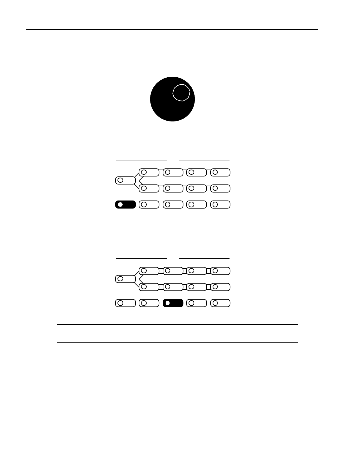
• The Value knob, when it’s turned clockwise or counter-clockwise, changes the setting of the
• The Enter button, when pressed, executes an operation, or functions as a “Yes” answer to a
currently selected parameter. It’s also used, in conjunction with the virtual tweak knobs, as a realtime controller (described later in this chapter).
Value
displayed question. When an Enter button-press is required to complete an operation, its LED
flashes.
Algo A Params A Mod A Bypass A
Routing
Algo B Params B Mod B Bypass B
Compare SaveEnter Cancel System
Edit
MIDI
• The Cancel button provides a mechanism for undoing edits and procedures. Its precise behavior
varies somewhat depending on what it is you’re doing and what’s showing on the DP/Pro’s
display. The procedures described throughout the Reference Manual detail the specific role that
the Cancel button plays in each context.
Algo A Params A Mod A Bypass A
Routing
Algo B Params B Mod B Bypass B
Compare SaveEnter Cancel System
Edit
MIDI
Tip: Many parameters in the DP/Pro can be reset to their nominal values by double-clicking
the Cancel button.
LEDs
The small lightbulbs—LEDs (for "Light Emitting Diode")—in many of the DP/Pro's buttons light to
help you keep track of where you are in the DP/Pro.
A Note About Read-Only Displays
Each of the areas within the DP/Pro has its own set of displays, which are described in detail in the
chapters of the DP/Pro Reference Manual. The DP/Pro provides a number of read-only displays for
informational purposes, in addition to its many adjustable parameters. When a displayed value is
2 ENSONIQ DP/Pro Reference Manual
Page 11
read-only, its name will be followed by a colon (“:”). The names of all editable parameters are
Effect
followed by an “equals” symbol (“=”).
Tip: See the Glossary in Chapter 13 for definitions of terms used in the DP/Pro Reference
Manual and software.
The DP /P r o Ar c hit e c t ur e
Effects
In the DP/Pro, an effect is a preset that contains all of the settings for the DP/Pro’s two processor
chips, as well as the settings that determine the flow of audio into, through and out of the DP/Pro.
1—Introduction
A DP/Pro Effect
ESP Processor Chip
(ESP-A)
Routing
Setting
ESP Processor Chip
(ESP-B)
The DP/Pro can contain up to 387 effects. Effects are stored in the DP/Pro’s memory in four banks:
• Banks 0 and 1 are RAM banks that can be used for the storage of effects you edit and create.
• Banks 2 and 3 are ROM banks that contain effects programmed by ENSONIQ; these effects are
always available and uneraseable.
Effects can be selected using the DP/Pro’s Select Effect button and the Value knob, with a foot switch
(such as the ENSONIQ SW-10) or with Program Changes and Bank Select messages received via
MIDI.
Select
Tweak Tap
Find
Previous Next
ENSONIQ DP/Pro Reference Manual 3
Page
Page 12
1—Introduction
Effect
Effect Finder
The DP/Pro offers a powerful mechanism for locating the desired effect from the many available in
memory. This mechanism—Effect Finder—searches for effects according to criteria that you provide.
Effect Finder is accessed via the Find button.
Select
Tweak Tap
Previous Next
Find
Page
To learn more about selecting effects and Effect Finder, see Chapter 3.
The DP/Pro’s Two ESP2 Processor Chips
The basic building blocks of DP/Pro effects are two of ENSONIQ’s second-generation 24-bit ESP2
custom VLSI chips. “ESP” is an acronym for “ENSONIQ Signal Processing.” The two chips are called
ESP-A and ESP-B.
Each ESP uses an algorithm—a highly specialized digital signal processing program—to perform an
audio processing task. The DP/Pro contains 42 different algorithms, any of which can be used by
either ESP. Each algorithm offers its own set of useful presets, called variations.
Algo A Params A Mod A Bypass A
Routing
Algo B Params B Mod B Bypass B
Edit
Algorithm and variation selection occurs after pressing the Algo A (for ESP-A) and Algo B (for ESP-B)
buttons. Chapter 5 explains in detail the manner in which algorithms and variations are selected.
Each algorithm contains a comprehensive suite of parameters, accessed via the Params A and Params
B button. Algorithms parameters are described in Chapter 6.
Algo A Params A Mod A Bypass A
Routing
Algo B Params B Mod B Bypass B
Edit
In addition, each ESP contains its own set of mix-related parameters that govern the ESP’s
input/output levels, stereo balances and, where applicable, its feedback settings. The mixer
parameters are also found under the Params A and Params B buttons. The ESP-A and ESP-B Mixer
Params are described in Chapter 8.
4 ENSONIQ DP/Pro Reference Manual
Page 13
The Contents of ESP-A and ESP-B
Effect
1—Introduction
input
controls
ESP-A
ALGORITHM
the algorithm's
parameters
output
controls
input
controls
ESP-B
ALGORITHM
the algorithm's
parameters
output
controls
Fast Editing of Parameters
The DP/Pro’s Tweak parameters system offers the ability to bring your most-commonly used ESP mix
and algorithm parameters up to the DP/Pro’s front panel. This provides quick access to these
parameters for editing without requiring you to navigate through all of the parameters available for
each ESP and algorithm. Chapter 9 describes the setup—via the Params A and Params B buttons,
shown above—and use—via the Tweak button—of Tweak parameters.
Select
Tweak Tap
Find
Previous Next
Page
Bypassing ESP-A and ESP-B
Either ESP can be disabled at any time by pressing the Bypass A and/or Bypass B buttons directly, via
a foot switch or from MIDI.
Edit
Algo A Params A Mod A Bypass A
Routing
Algo B Params B Mod B Bypass B
The DP/Pro offers a range of bypass options that allow you to control what it means to “turn off” an
ESP. These options are described in Chapter 2.
Copying and Swapping Algorithms
The DP/Pro provides a selection of tools for moving algorithms and their settings from one ESP to
another, or between effects. These tools, available under the Routing button (shown below), are
described in Chapter 7.
ENSONIQ DP/Pro Reference Manual 5
Page 14
1—Introduction
Routing
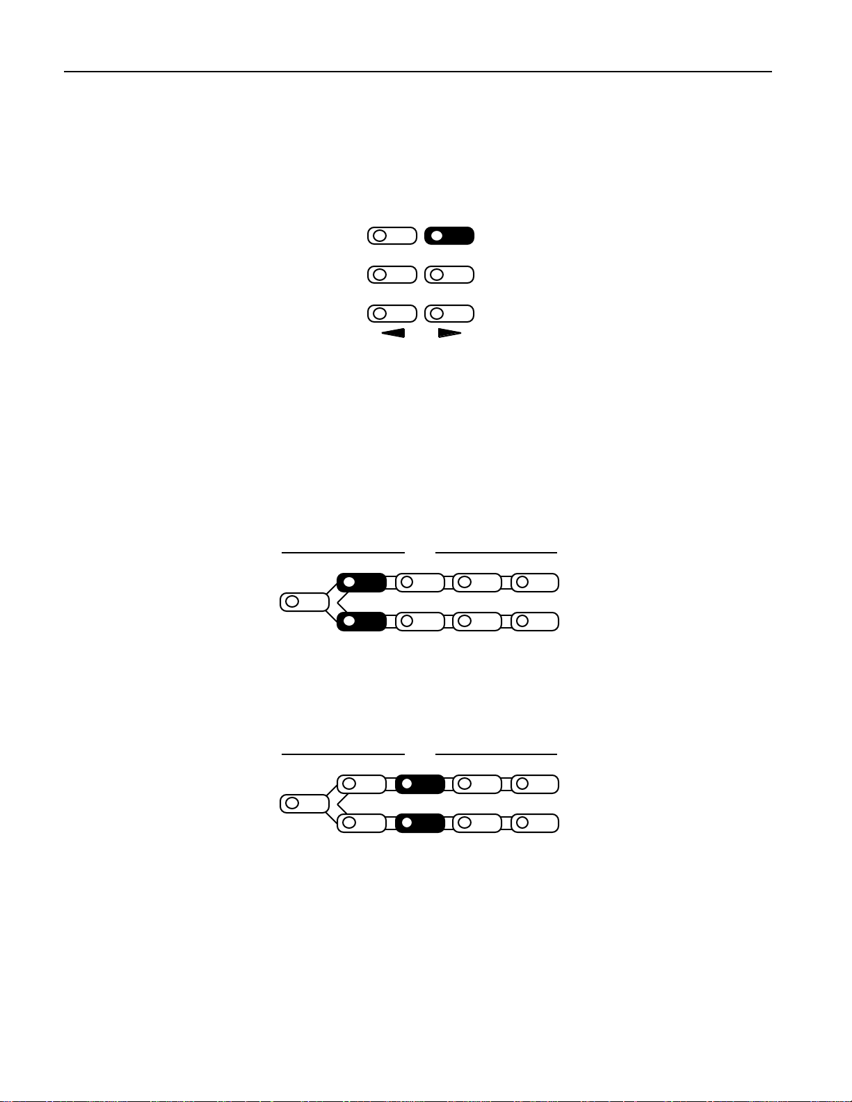
The DP/Pro provides a variety of ways in which you can pass audio into the DP/Pro, through the
ESPs, and back out again. This is referred to as signal routing.
• You can process audio sent into the DP/Pro’s left and right inputs as a single stereo feed, or as
• When you process stereo audio, you can arrange the two ESPs so that signal passes through them
• You can also determine whether the stereo outputs of the ESPs will be mixed together, presenting
Routing options are access by pressing the Routing button. Chapter 4 describes the DP/Pro’s routing
options in detail.
two separate mono signals.
separately, from ESP-A into ESP-B, or in a feedback loop, where audio goes into ESP-A, then ESPB ,and then back to ESP-A again.
a single stereo feed at the DP/Pro’s outputs, or whether the ESPs will each use their own single
output.
Algo A Params A Mod A Bypass A
Routing
Algo B Params B Mod B Bypass B
Edit
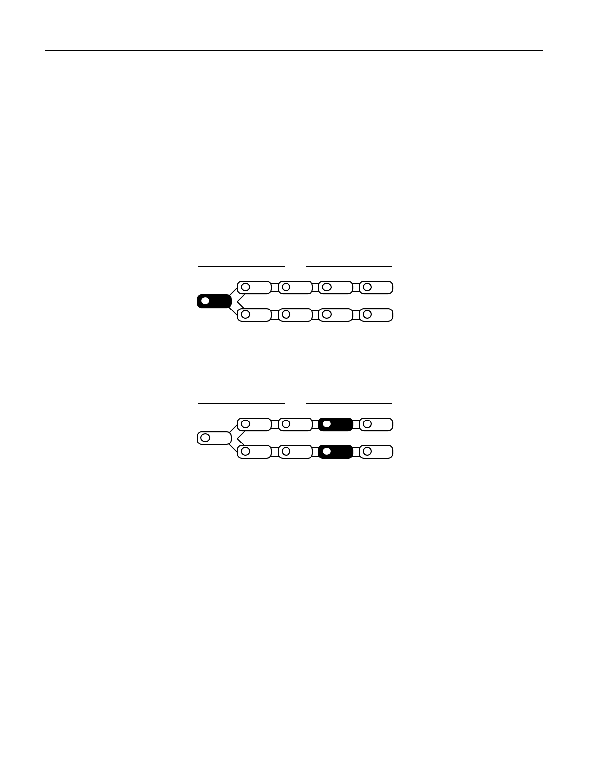
Real-Time Effect Modulation
The DP/Pro provides an extensive set of tools that allow for the real-time manipulation, or modulation,
of effects. The Mod A and Mod B buttons are provided for this purpose.
Algo A Params A Mod A Bypass A
Routing
Algo B Params B Mod B Bypass B
The setting of any ESP mix or algorithm parameter can be controlled in real-time. Real-time
modulation can be performed using any MIDI controller, a stereo foot switch, a CV pedal or the
DP/Pro’s unique virtual controllers, its Tweak knobs, or mod LFOs.
The Virtual Tweak Knobs
Each effect in the DP/Pro contains two virtual controllers called Tweak Knob 1 and Tweak Knob 2.
These two devices are software objects that, when enabled, are controlled by the front-panel Value
knob. The tweak knobs can be used for the modulation of any ESP mix or algorithm parameters in
either ESP, and can be assigned names in order to help you keep track of what it is you’ve
programmed them to do.
Edit
The Mod LFOs
In addition to the LFOs available within the DP/Pro’s algorithms, two free-standing LFOs are
available at all times for use as real-time modulators of ESP mix and algorithm parameter settings in
either ESP: the mod LFOs. These LFOs can provide cyclical changes to parameters’ settings, as they
cycle back and forth through their low-frequency waves.
Real-time effect modulation, the tweak knobs and mod LFOs are described in detail in Chapter 9.
6 ENSONIQ DP/Pro Reference Manual
Page 15
1—Introduction
Effect
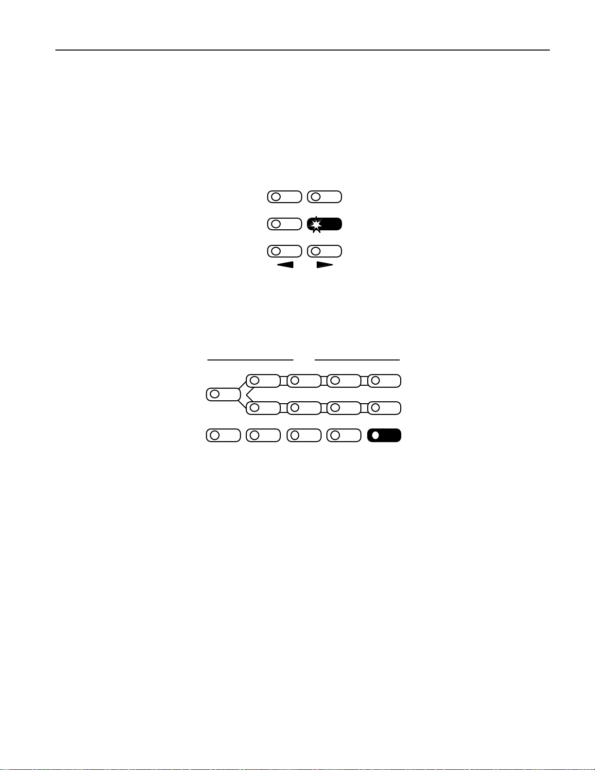
Synchronizing Effects to a Tempo
Many of the DP/Pro’s algorithms contain elements that can be synchronized to a timing reference. The
DP/Pro contains a system clock to provide such a pulse. The system clock can be set to be internally
controlled or to respond to received MIDI clocks. When the system clock is not linked to an external
MIDI timing source, its rate may be set manually, or by tapping the desired tempo on the front-panel
Tap button. The Tap button—whose LED flashes the current system tempo—is itself highly
configurable. Chapter 2 provides information on the system clock and setting up the Tap button.
Select
Tweak Tap
Previous Next
Find
Page
The DP/Pro and MIDI
The DP/Pro is a MIDI-conversant device, allowing the selection of effects, bypassing and real-time
modulation via MIDI. The DP/Pro’s basic MIDI characteristics are provided in its System/MIDI
parameters, described in Chapter 2.
Algo A Params A Mod A Bypass A
Routing
Algo B Params B Mod B Bypass B
Compare SaveEnter Cancel System
Edit
MIDI
Defining your DP/Pro Workspace
The DP/Pro’s overall operation is quite customizable. The System/MIDI button —shown
above—provides access to the many parameters that allow you to make your DP/Pro working
environment comfortable. The System/MIDI parameters are described in Chapter 2.
Important: Two Final Concepts
Downloading and Installing
In the DP/Pro, the selection of an effect, algorithm or algorithm variation does not necessarily mean
that it’s ready for use:
• When an effect is selected, the DP/Pro must be instructed to download all of the effect’s
algorithm settings into its ESPs, and to configure the effect’s signal routing.
• When an algorithm or algorithm variation is selected, the DP/Pro must be instructed to
download all of the algorithm’s settings into the selected ESP.
The DP/Pro allows you to choose whether you’d like it to download, or install, these objects as they’re
ENSONIQ DP/Pro Reference Manual 7
selected, or whether you’d like the option of installing effects and/or algorithms (and variations)
manually by pressing the Enter button after you’ve selected them. If you choose the latter, the Enter
button will flash after you’ve selected an effect, algorithm or algorithm variation to remind you that it
needs to be pressed.
Page 16
1—Introduction
Algo A Params A Mod A Bypass A
Routing
Algo B Params B Mod B Bypass B
Compare SaveEnter Cancel System
The System/MIDI AutoLoad parameter allows you to determine the DP/Pro’s behavior in this regard.
When the DP/Pro is shipped from the factory, algorithms and algorithm variations are set to
automatically download, while effects are set for manual installation.
Edit
MIDI
Saving
When you’re editing effects in the DP/Pro—including every non-System/MIDI parameter—the
changes you make are not permanent until you save the effect you’re working on. See Chapter 11 to
learn how to save effects to the DP/Pro’s memory.
Algo A Params A Mod A Bypass A
Routing
Algo B Params B Mod B Bypass B
Compare SaveEnter Cancel System
Edit
A vailable Op tions for t he DP /P r o
• ENSONIQ SW-10 Dual Foot Switch—provides left and right foot pedals in a single unit. These
foot pedals can be configured to perform many tasks in the DP/Pro.
• ENSONIQ DI-Pro Digital I/O Board—provides AES-EBU and S/PDIF digital inputs and outputs
for the DP/Pro. The DI-Pro is user-installable.
• ADC-24—upgrades the DP/Pro’s analog-to-digital and digital-to-analog converters from 20-bit to
24-bit performance. The ADC-24 is user-installable.
Inst alling th e DP /P r o
Powering Up the First Time
The correct procedure for powering up the DP/Pro for the first time is as follows:
1. Make sure the DP/Pro’s power button is turned off—the bottom of the button should be pressed
in.
2. Plug the provided line cord into the AC line receptacle on the rear panel of the DP/Pro.
3. Plug the other end of the line cord into a grounded AC outlet.
4. Press the top of the Power button on the right side of the DP/Pro’s front panel.
Powering up the DP/Pro in a MIDI Configuration
In a series of MIDI devices, you should always turn on the device that’s transmitting MIDI data
(keyboards, sequencers, etc.) before you power up the device that’s receiving MIDI data. For instance,
if you’re using the DP/Pro to receive MIDI information from a keyboard or sequencer, you should
turn the keyboard or sequencer on before the DP/Pro. This prevents any unwanted MIDI information
MIDI
8 ENSONIQ DP/Pro Reference Manual
Page 17
1—Introduction
from being “spit” out of the transmitting device during power up, which could confuse or disable
your DP/Pro. If this should happen, turn off the DP/Pro, and then turn it back on.
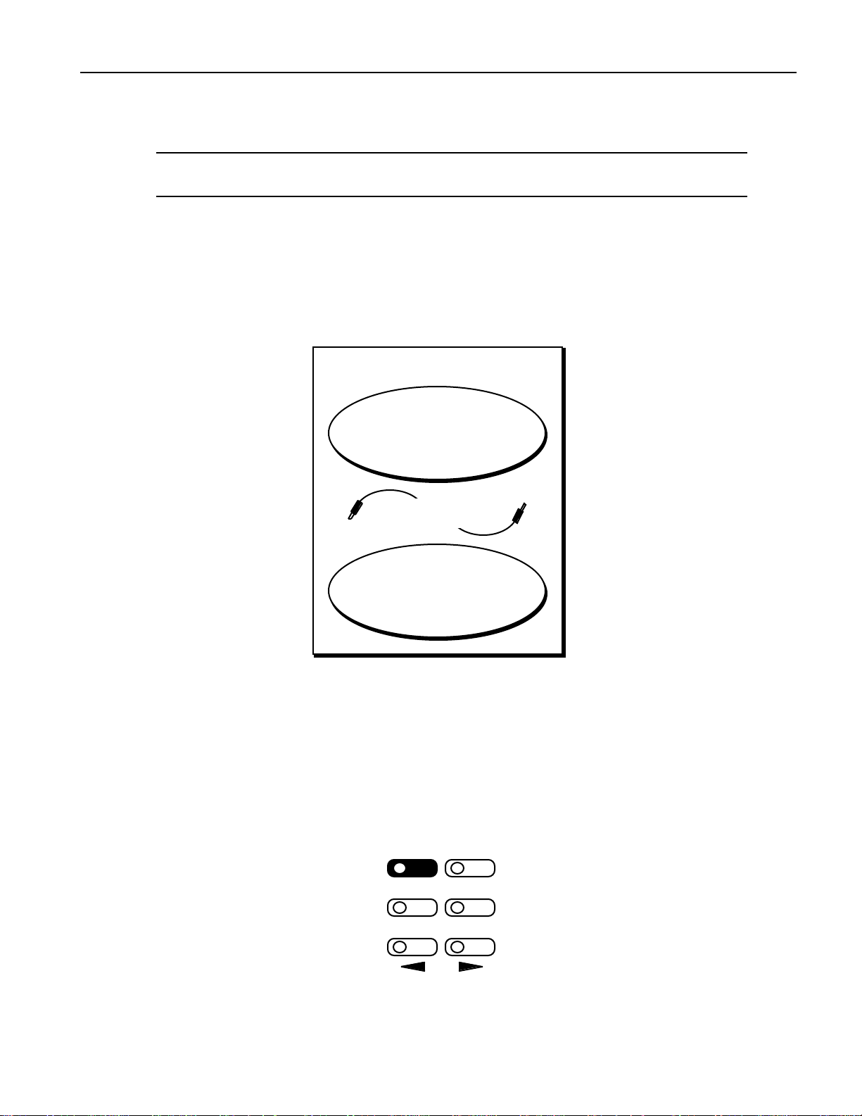
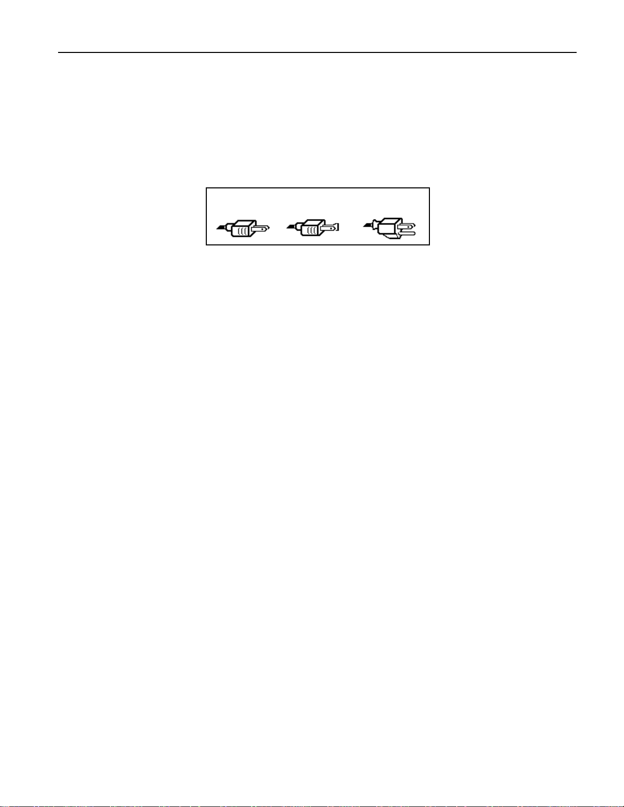
Polarization and Grounding
Like many modern electrical devices, the DP/Pro has a three-prong power cord with earth ground to
ensure safe operation. Some products have power cords with only two prongs and no earth ground.
For safety, some of these products have polarized plugs which can only be inserted into an outlet the
proper way.
Three-prong
PolarizedNon-polarized
Some products, such as older guitar amplifiers, do not have polarized plugs and can be connected to
an outlet incorrectly. This may result in dangerous high voltages on the audio connections, which
could cause you physical harm, or damage any properly grounded equipment to which they are
connected, such as your DP/Pro.
To avoid shock hazards or equipment damage, we recommend the following precautions:
• If you own equipment with two-pronged power cords, check to see if they’re polarized or nonpolarized. You might consider having an authorized repair station change any non-polarized
plugs on your equipment to polarized plugs to avoid future problems.
• Exercise caution when using extension cords or plug adapters. Proper polarization should always
be maintained from the outlet to the plug. The use of polarized extension cords and adapters is
the easiest way to maintain proper polarity.
• Whenever possible, connect all products with grounded power cords to the same outlet ground.
This will ensure a common ground level to prevent equipment damage and minimize hum in the
audio output.
AC outlet testers are available from many electronic supply and hardware stores. These can be used to
check for proper polarity of outlets and cords.
with earth ground
For more information on grounding the DP/Pro, see Chapter 12.
AC Line Conditioning
As with any computer device, the DP/Pro is sensitive to sharp peaks and drops in the AC line voltage.
Lightning strikes, power drops, or sudden and erratic surges in the AC line voltage can scramble the
internal memory, and in some cases, damage the unit’s hardware. Here are a few suggestions to help
guard against such occurrences:
• A surge/spike suppressor—this absorbs surges and protects your gear from all but the most
severe over-voltage conditions. You can get multi-outlet power strips with built-in surge/spike
suppressors for little more than the cost of unprotected power strips, so purchasing one is a good
investment for all your electronic equipment.
• A line conditioner—this is the best, but by far the more expensive way to protect your gear. In
addition to protecting against surges and spikes, a line conditioner guards equipment against
excessively high or low line voltages. If you use the DP/Pro in lots of different locations with
varying or unknown AC line conditions, you might consider investing in a line conditioner.
Rack Mounting Guidelines
Because the DP/Pro uses an internal transformer, it generates a certain amount of heat. For better
reliability, we don’t recommend the installation of the DP/Pro near devices that are particularly
sensitive to heat, or near power amps, tube equipment, or other products that emit a lot of heat.
ENSONIQ DP/Pro Reference Manual 9
Page 18
1—Introduction
Temperature Guidelines
The DP/Pro contains computerized and electronic circuitry that can be susceptible to damage when
exposed to extreme temperature changes. When the DP/Pro is brought inside after sitting in a cold
climate (i.e., the back seat of your car), condensation builds up on the internal circuitry in much the
same way a pair of glasses fogs up when you come inside on a cold day. If the unit is powered up as
this condensation occurs, components can short out or be damaged. Excessively high temperatures
also pose a threat to the unit, stressing both the internal circuits as well as the case. With this in mind,
we advise you to follow these precautions when storing, mounting and setting up your DP/Pro:
• Avoid leaving the DP/Pro in temperatures of less than 50 degrees Fahrenheit or more than 100
degrees Fahrenheit.
• When bringing the DP/Pro indoors after travel, allow at least 20 minutes for the unit to reach
room temperature before powering up. In the case of extreme outdoor temperatures (below 50
degrees Fahrenheit or above 100 degrees Fahrenheit), allow an hour or more before powering up.
• Avoid leaving the DP/Pro inside a vehicle exposed to direct sunlight.
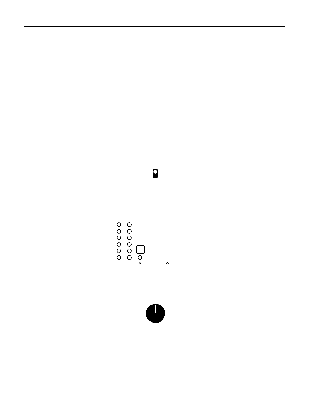
Se t t ing A nalog Input Le ve ls
The DP/Pro can accept +4dB or -10dB input levels. The rear panel I/O level switch should be set to
match the output of your sending device.
+4 dBu
-10 dBv
I/O Level
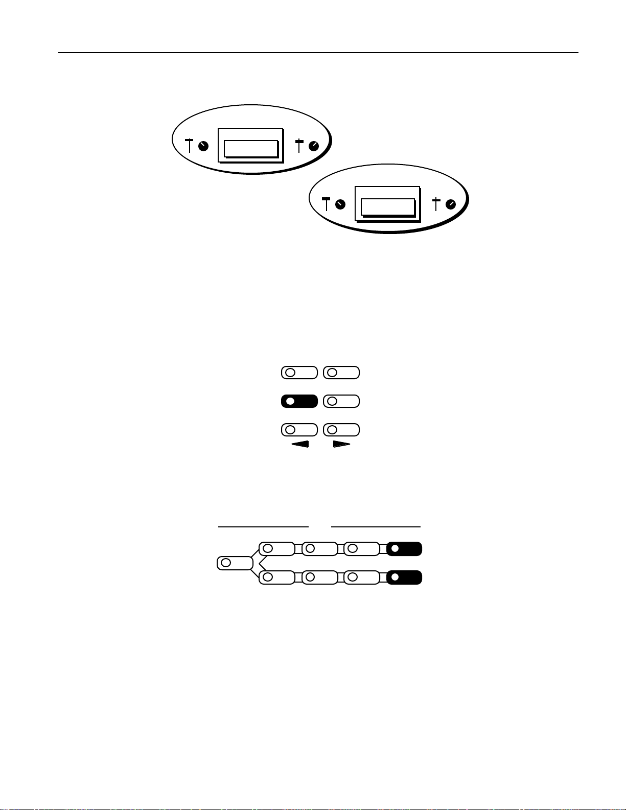
The DP/Pro’s Headroom LEDs show the level of incoming analog audio whenever the Meter Function
switch is in the out, or up, position. The LEDs under the Meter Function switch show the current state
of the Headroom LEDs.
Headroom
0
3
6
12
20
30
L R
Meter
Function
Analog Input
Digital Output
The optimal input level for the DP/Pro is just below the point at which the red Headroom LEDs light.
Since the DP/Pro provides its best signal-to-noise performance when its Input Level knob is set
straight up, it’s a good idea to set the knob to this position and then adjust the output levels of your
sending device to obtain a healthy Headroom LED reading.
Input Level
(Stereo)
Tr ouble shoot ing
Battery Replacement
The DP/Pro “remembers” its effects and various settings even when its power is turned off, since it
contains a battery which keeps its memory intact. All batteries eventually become discharged, and
10 ENSONIQ DP/Pro Reference Manual
Page 19

1—Introduction
though your DP/Pro battery should last for years, you may eventually need to have it replaced by an
authorized ENSONIQ Repair Station.
The DP/Pro will tell you when its battery needs replacing. It will flash the following when you power
up:
Warning! Main battery is
low. See manual.
This display will appear only briefly, and then allow you to proceed normally. Make sure that
everything in RAM that you’d like to keep—or any special system settings—have been safely stored
on an external MIDI storage device—as described in Chapter 2—and take the DP/Pro to an
authorized ENSONIQ Repair Station as soon as possible to have the battery replaced.
Reinitializing the DP/Pro
All computer-based devices—including the DP/Pro—occasionally experience signs of data
corruption. If your DP/Pro begins acting oddly, you can reinitialize its software to clear out any
problems lurking there.
Warning: Make sure you’ve saved any effects or system settings that you want to preserve to
an external MIDI device before reinitializing. Reinitializing erases the contents of the
DP/Pro’s user memory banks, and resets all System/MIDI parameters to their default values.
To Reinitialize the DP/Pro
1. Hold down the System/MIDI button.
2. While continuing to hold the System/MIDI button, press the Cancel button.
3. Let go of both buttons. The displays shows:
Press ENTER to Reinit. All data
will be lost!
4. Press the Enter button to reinitialize the DP/Pro.
ENSONIQ DP/Pro Reference Manual 11
Page 20
2—System/MIDI Parameters
2—System/MIDI Parameters
What A r e the Global Syst e m and MID I P ar am e t e r s?
The global System and MIDI parameters provide options for determining the overall behavior of your
DP/Pro. These parameters create the framework within which all other DP/Pro operations occur.
Certain special procedures are also available via the System/MIDI parameter pages.
All of the System and MIDI parameters are accessed by:
• pressing the System/MIDI button.
Algo A Params A Mod A Bypass A
Routing
Algo B Params B Mod B Bypass B
Compare SaveEnter Cancel System
• pressing the Next and Previous Page buttons to navigate among the parameters.
• turning the Value knob to set the selected parameter’s value.
Tip: When you’ve altered a parameter’s value, you can press the Cancel button to undo your
edit. You can also double-click the Cancel button to quickly set any parameter to its default
value.
Tip: Important System/MIDI parameters are bookmarked for easy access. Press the
System/MIDI button repeatedly to jump from one bookmarked parameter to the next. You
can also use this technique to quickly access any System/MIDI parameter by jumping to the
nearest bookmark and then using the Next or Previous Page buttons to locate the parameter
you want.
Edit
MIDI
The Numbering of the System/MIDI Parameters
The System/MIDI parameters are numbered—as each parameter is selected, its number appears in the
auxiliary display to the left of the DP/Pro’s main display.
“P” stands for “parameter”
m
P 27
i
This shows the number of the currently displayed and selected parameter
ENSONIQ DP/Pro Reference Manual 1
Page 21

2—System/MIDI Parameters
Se le c t ing t he Type of Audio t o be P r oc e sse d
The first step in using the DP/Pro is determining the type of audio you’ll be sending into its input
jacks. All DP/Pros can process analog audio. Any DP/Pro with an ENSONIQ DI-Pro digital I/O
board installed can also process incoming digital audio in AES and S/PDIF formats.
System/MIDI Parameter 1: Input
k
Input=Analog Clock=48.000
kHz
Values: Analog; Digital, AES; Digital, S/PDIF; Ana+Dig, AES; Ana+Dig, S/PDIF
Default: Analog
Note: The listed values are available when the optional DI-Pro digital I/O board is installed in
the DP/Pro. When the DI-Pro board is not present, only the Analog setting is visible.
What this Parameter Does:
The Input parameter selects the type of audio source you’ll be sending into the DP/Pro. Rear-panel
combination 1/4”/XLR jacks are provided for analog signals, and the optional DI-Pro digital I/O
board provides digital inputs for AES- and S/PDIF-format data.
Est ablishing the D P /P r o’ s Sam ple Rat e
The DP/Pro’s A/D and D/A converters can operate at several different sample rates.
When an analog signal is being processed, the DP/Pro can operate at either 44.100 kHz or 48.000 kHz.
Both rates have their advantages and disadvantages. The 48.000 kHz provides the highest-quality
signal processing. However, should you be using the DP/Pro’s digital outputs to master an analog
signal to CD or some other digital medium that operates at 44.100 kHz, you’ll need to use the same
sample rate in the DP/Pro.
Note: The DP/Pro’s Sample Rate LEDs—located above the auxiliary display—show the
DP/Pro’s current sample rate.
System/MIDI Parameter 2: Clock
Input=Analog Clock=48.000
k
Values: 44.100 kHz (when Input=Analog); 48.000 kHz (when Input=Analog)
Default: 48.000 kHz
2 ENSONIQ DP/Pro Reference Manual
kHz
Page 22

What this Parameter Does:
The Clock parameter sets or displays the sample rate used by the DP/Pro’s A/D and D/A converters.
The behavior of this parameter is dependent on the setting of the Input parameter.
• When Input=Analog, the setting of the Clock parameter determines the operating sample rate of
the DP/Pro.
System/MIDI parameters 3 through 5 are available only when a DI-Pro digital I/O board has been
installed in the DP/Pro. See the DI-Pro User’s Guide for information on these parameters.
Global MID I Se t t ings
The DP/Pro is a highly MIDI-aware device:
• DP/Pro effects can be selected via MIDI Program Change and Bank Select messages.
• Effects can be modulated in real time using any MIDI controller.
• Many aspects of DP/Pro algorithms can be synchronized to MIDI clocks.
• The DP/Pro generates and responds to System Exclusive data dumps.
• The DP/Pro can transmit control change messages generated by its virtual Tweak knobs, its
Bypass buttons and its dual foot switch.
• The DP/Pro can transmit Program Change messages when effects are selected from the front
panel, or by using a foot switch.
• Various elements of MIDI transmission and reception can be individually enabled or disabled;
the DP/Pro also provides an overall MIDI reception on/off parameter.
• The DP/Pro’s response to Program Change messages can be re-mapped to allow any Program
Change value to select any effect.
The DP/Pro uses three MIDI channels. Program Changes received on the System MIDI channel select
effects, while ESP-A and ESP-B each have their own MIDI channels upon which they receive MIDI
controller messages used for the real-time manipulation of their algorithms.
2—System/MIDI Parameters
System/MIDI Parameter 6: MIDI Device ID
k
MIDI Device ID=0 System
MIDI Channel=1
Values: 0 through 127
Default: 0
What this Parameter Does:
System Exclusive data is always stamped with a MIDI Device ID number. This is used to identify an
individual device in MIDI setups that contain more than one of a particular product. If you are using
multiple DP/Pros, make sure that each has been assigned its own Device ID number if you intend to
be working with System Exclusive data. This includes external MIDI storage devices, as well as remote
editing software on a computer.
ENSONIQ DP/Pro Reference Manual 3
Page 23

2—System/MIDI Parameters
System/MIDI Parameter 7: System MIDI Channel
k
Values: 1 through 16
Default: 1
What this Parameter Does:
MIDI Program Change and Bank Select messages received on the System MIDI channel select effects
(see Chapter 3 to learn more about selecting effects via MIDI). This parameter allows you to set the
System MIDI channel to any of the 16 MIDI channels.
System/MIDI Parameter 8: ESP-A MIDI Channel
System/MIDI Parameter 9: ESP-B MIDI Channel
MIDI Device ID=0 System
MIDI Channel=1
ESP-A MIDI Channel=2 ESP-B
MIDI Channel=3
Values: 1 through 16
Defaults: ESP-A MIDI Channel: 2; ESP-B MIDI Channel: 3
What this Parameter Does:
Any parameter in any DP/Pro algorithm can be manipulated in real time via MIDI controller
messages. ESP-A and ESP-B each have their own MIDI channel upon which they receive such MIDI
data. Either may be set to respond to any MIDI channel.
System/MIDI Parameter 10: Accept MIDI Msgs
k
Accept MIDI Msgs=Yes Accept
SysEx Msgs=Yes
Values: No; Yes
Default: Yes
What this Parameter Does:
The Accept MIDI Msgs parameter enables or disables the DP/Pro’s response to MIDI messages of any
kind.
Note: When this parameter is set to “No,” the settings of System/MIDI parameters 11 through
13 will have no effect.
System/MIDI Parameter 11: Accept SysEx Msgs
4 ENSONIQ DP/Pro Reference Manual
Page 24
2—System/MIDI Parameters
Accept MIDI Msgs=Yes Accept
k
Values: No; Yes
Default: Yes
What this Parameter Does:
The Accept SysEx Msgs parameter enables or disables the DP/Pro’s ability to accept or load received
System Exclusive messages.
Note: If the Accept MIDI Msgs parameter is set to “Off,” this parameter will have no effect,
since the Accept MIDI Msgs parameter will have completely disabled overall MIDI reception.
SysEx Msgs=Yes
System/MIDI Parameter 12: Accept Cntlr Msgs
k
Accept Cntlr Msgs=Yes Accept
PrgCh Msgs=Yes
Values: No; Yes
Default: Yes
What this Parameter Does:
The Accept Cntlr Msgs parameter enables or disables the DP/Pro’s response to received MIDI
controller messages.
Note: If the Accept MIDI Msgs parameter is set to “Off,” this parameter will have no effect,
since the Accept MIDI Msgs parameter will have completely disabled overall MIDI reception.
System/MIDI Parameter 13: Accept PgmCh Msgs
Accept Cntlr Msgs=Yes Accept
k
Values: No; Yes
Default: Yes
PrgCh Msgs=Yes
What this Parameter Does:
The Accept PrgCh Msgs parameter enables or disables the DP/Pro’s response to received MIDI
Program Change and Bank Select messages.
Note: If the Accept MIDI Msgs parameter is set to “Off,” this parameter will have no effect,
since the Accept MIDI Msgs parameter will have completely disabled overall MIDI reception.
ENSONIQ DP/Pro Reference Manual 5
Page 25

2—System/MIDI Parameters
System/MIDI Parameter 14: Transmit Cntlr Msgs
k
Transmit Cntlr Msgs=No
Transmit PrgCh Msgs=No
Values: No; Yes
Default: No
What this Parameter Does:
The Transmit Cntlr Msgs parameter enables or disables the DP/Pro’s transmission of MIDI controller
data from either of its virtual Tweak knobs, bypass button or dual foot switch.
System/MIDI Parameter 15: Transmit PrgCh Msgs
Transmit Cntlr Msgs=No
k
Values: No; Yes
Default: No
What this Parameter Does:
The DP/Pro can transmit a corresponding Program Change and Bank Select message each time you
select an effect from the DP/Pro’s front panel. The Transmit PrgCh Msgs parameter enables or
disables this feature.
Transmit PrgCh Msgs=No
System/MIDI Parameter 16:MIDI Pgm Chngs
k
MIDI Pgm Changes=Direct
Map=000 > Effect=None
Values: Direct; Use Map
Default: Direct
What this Parameter Does:
The MIDI Pgm Chngs parameter determines the manner in which the DP/Pro will respond to
received Bank Select and Program Change messages. When the parameter is set to:
• “Direct,” each received Bank Select and Program Change message will select the like-numbered
bank and effect.
• “Use Map,” you can designate the effects to be selected by particular Program Change values.
This parameter functions in conjunction with System/MIDI parameters 17 and 18, described below.
System/MIDI Parameter 17: Map
6 ENSONIQ DP/Pro Reference Manual
Page 26

2—System/MIDI Parameters
MIDI Pgm Changes=Direct
Map=000 > Effect=None
i
Values: 000 to 127
Default: 000
What this Parameter Does:
The Map parameter operates in conjunction with System/MIDI parameters 16 and 18. It selects a
Program Change value to be linked to the effect selected with parameter 18 whenever parameter 16 is
set to “Use Map.”
System/MIDI Parameter 18: (Map) Effect
MIDI Pgm Changes=Direct
Map=000 > Effect=None
i
Values: None; 0000* through 3005
Default: None
What this Parameter Does:
The Effect parameter operates in conjunction with System/MIDI parameters 16 and 17, described
above. Set the Effect parameter to the number of the effect you’d like selected when the DP/Pro
receives the Program Change value displayed in the Map field to its left. This feature is active only
when parameter 16 is set to “Use Map.”
Each effect is shown as a four-digit number. The first digit represents the bank in which the effect is
stored. The three remaining digits show the program number of each effect within the selected bank.
If System/MIDI parameter 76 is set to “Yes,” an asterisk following the effect’s bank and program
numbers shows that the memory location is currently empty. ” If parameter 76 is set to “No,” unused
locations will not be available for selection by this parameter.
ENSONIQ DP/Pro Reference Manual 7
Page 27

2—System/MIDI Parameters
System/MIDI Parameter 19: ENTER to Send SysEx Dump Type
ENTER to Send SysEx Dump
Type=Bank 0 RAM Effects
Values: Selected Effect; Bank 0 RAM Effects; Bank 1 RAM Effects; All RAM Effects; All System Params (this
Default: Bank 0 RAM Effects
includes all System/MIDI parameter settings)
What this Parameter Does:
When this page is displayed, pressing the Enter button causes the DP/Pro to transmit a System
Exclusive (SysEx) data dump of the object selected on the lower line of the display. This provides an
opportunity to store the contents of the DP/Pro’s memory in an external MIDI storage device.
Note: Since SysEx data records the MIDI Device ID number of the sending device, make sure
to note the setting of the MIDI Device ID parameter (System/MIDI parameter 6) when
performing the dump. In order to successfully reload the data back into the DP/Pro at a later
date, this Device ID number must match the one embedded in the SysEx data. In addition, the
Accept SysEx Msgs System/MIDI parameter (12) must be set to “Yes” in order for the DP/Pro
to reload SysEx data transmitted from an external source.
Se t t ing U p a R e f e r e nc e for Tim e - Base d Ef f e c t s
Many of the DP/Pro’s algorithms contain time-based elements—LFOs and delays, for example—that
can be synchronized to a timing reference. This provides a high degree of timing control of those
elements. The DP/Pro provides its own internal clock for such purposes, or it can synchronize its
algorithms to MIDI clocks received from and external MIDI device.
Tip: The algorithm parameter charts in Chapter 6 of the DP/Pro Reference Guide show which
algorithm elements are capable of synchronization. Any parameter with the letter “T” (for
“Time”) in its Attributes column can be synchronized.
The DP/Pro’s internal clock can be set by manually adjusting the System/MIDI System Tempo
parameter, or by tapping out the desired tempo on the Tap button. The DP/Pro can be set to respond
to Tap button strikes in a variety of ways.
System/MIDI Parameter 20: Tempo Source
k
Tempo Source=Internal System
Tempo=120 BPM
Values: Internal; MIDI Clock
Default: Internal
8 ENSONIQ DP/Pro Reference Manual
Page 28

2—System/MIDI Parameters
What this Parameter Does:
The Tempo Source parameter determines the master timing reference source for the DP/Pro. The
DP/Pro uses its own internal clock when Tempo Source is set to “Internal.” The DP/Pro can also use
MIDI clocks received from an external source when this parameter is set to “MIDI Clock.”
System/MIDI Parameter 21: System Tempo
Tempo Source=Internal System
k
Values: 40 BPM through 400 BPM
Default: 120 BPM
What this Parameter Does:
The System Tempo parameter sets the speed of the DP/Pro’s internal clock, shown in Beats Per
Minute (BPM). When the System/MIDI Tempo Source parameter (16) is set to “Internal,” the System
Tempo parameter provides control over the timing of any synchronized algorithm elements.
Tempo=120 BPM
Tip: You can also set the tempo of the DP/Pro’s internal clock by tapping the desired tempo
on the DP/Pro’s Tap button.
System/MIDI Parameter 22: Tapped Note
k
Tapped Note=1/4 Note Tap
Average=2 TapLED=On
Values: 4 Beats Dotted 1/4 1/8 Note 1/16 Triplet
3 Beats 1/4 Note 1/8 Triplet Dotted 1/32
1/2 Note 1/4 Triplet Dotted 1/16 1/32 Note
1/2 Triplet Dotted 1/8 1/16 Note 1/32 Triplet
Default: 1/4 Note
What this Parameter Does:
The Tapped Note parameter determines the note value ascribed to each Tap button strike when the
DP/Pro calculates its system tempo from the Tap button.
System/MIDI Parameter 23: Tap Average
Tapped Note=1/4 Note Tap
Average=2 TapLED=On
i
Values: 2 through 8
Default: 2
What this Parameter Does:
ENSONIQ DP/Pro Reference Manual 9
Page 29

2—System/MIDI Parameters
The Tap Average parameter determines the number of Tap button strikes the DP/Pro will average in
order to calculate the timing of the system tempo. You can also set the note value of each tap—see
System/MIDI parameter 20, Tapped Note.
System/MIDI Parameter 24: TapLED
Tapped Note=1/4 Note Tap
Average=2 TapLED=On
i
Values: Off; On
Default: On
What this Parameter Does:
The TapLED parameter turns on or off the LED in the DP/Pro’s Tap button. The Tap LED flashes at
the current system tempo when this parameter is set to “On.”
C r e at ing Y our Ow n A pp Cat e gor y f or Ef f e c t F inde r
The DP/Pro’s Effect Finder can search for effects according to the manner in which they’re used.
These possible uses are presented as the various App—for “Application”—categories in Effect Finder
(for more on using Effect Finder, see Chapter 3). You can also create up to 10 of your own usage
categories for situations not covered by those already written into the DP/Pro’s software. Each can
contain up to 10 effects This will allow you to use Effect Finder to locate effects according to your
unique needs.
Each of the 10 user-defined categories can be selected from among the App values in Effect
Finder—they’re listed as Groups 1 to 10.
System/MIDI Parameter 25: Finder App Group
k
Finder App Group =1 Item=1 >
Effect=None
Values: 1 through 10
Default: 1
What this Parameter Does:
The Finder App Group parameter selects one of the 10 App groups. Once you’ve selected a group, you
can choose the effects you want to assign to the group by assigning an effect to each item number.
10 ENSONIQ DP/Pro Reference Manual
Page 30

2—System/MIDI Parameters
System/MIDI Parameter 26: Item
Finder App Group =1 Item=1 >
Effect=None
i
Values: 1 through 10
Default: 1
What this Parameter Does:
The Item parameter selects one of the 10 items—you can think of this as a slot—available in the
selected App group.
System/MIDI Parameter 27: (App Group) Effect
Finder App Group =1 Item=1 >
Effect=None
i
Values: None; 0000* through 3005
Default: None
What this Parameter Does:
The Effect parameter allows you to assign one of the DP/Pro’s effects to the currently selected item.
Each effect is shown as a four-digit number. The first digit represents the bank in which the effect is
stored. The three remaining digits show the program number of each effect within the selected bank.
If System/MIDI parameter 76 is set to “Yes,” an asterisk following the effect’s bank and program
numbers shows that the memory location is currently empty. ” If parameter 76 is set to “No,” unused
locations will not be available for selection by this parameter.
Gr ouping Ef fe c t s for Easy Se le c t ion
The DP/Pro allows you to group effects together as songs—a DP/Pro song is a list of effects meant to
be selected one after the other. A song can use any of the effects in the DP/Pro, arranged in any order.
There can be up to 10 steps in each song—each step being associated with a single effect—and up to 10
songs in the DP/Pro’s memory at any given time. You can move forward or back through the list by
pressing the pedals on a dual foot switch—such as an ENSONIQ SW-10 (see the System/MIDI L Ftsw
Cntlr and R Ftsw Cntlr parameters below).
ENSONIQ DP/Pro Reference Manual 11
Page 31

2—System/MIDI Parameters
System/MIDI Parameter 28: Song
Values: 1 through 10
Default: 1
What this Parameter Does:
The Song parameter selects one of the 10 DP/Pro songs. Once you’ve selected a song, you can name
the song, and then assign an effect to each of its steps.
System/MIDI Parameters 29-39: Name
m
Song=1 Name=Undefined Step=1
> Effect=None
m
Song=1 Name=Undefined Step=1
> Effect=None
Values: Symbols, numbers, upper- and lower-case characters
Default: “Undefined”
What these Parameters Do:
The System/MIDI song page’s Name fields allow you to name the song you’re constructing. Use the
Next and Previous Page buttons to underline each character in turn—when a character is underlined,
it can be edited. Turn the Value knob to select the desired character.
System/MIDI Parameter 40: Step
Song=1 Name=Undefined Step=1
> Effect=None
i
Values: 1 through 10
Default: 1
What this Parameter Does:
The Step parameter selects one of the 10 steps available in the selected song.
12 ENSONIQ DP/Pro Reference Manual
Page 32

2—System/MIDI Parameters
System/MIDI Parameter 41: (Song) Effect
Song=1 Name=Undefined Step=1
> Effect=None
i
Values: None; 0000* through 3005
Default: None
What this Parameter Does:
The Effect parameter allows you to assign any of the DP/Pro’s effects to the step currently selected
with the Step parameter.
Each effect is shown as a four-digit number. The first digit represents the bank in which the effect is
stored. The three remaining digits show the program number of each effect within the selected bank.
If System/MIDI parameter 76 is set to “Yes,” an asterisk following the effect’s bank and program
numbers shows that the memory location is currently empty. ” If parameter 76 is set to “No,” unused
locations will not be available for selection by this parameter.
D e signat ing R e al- Tim e Cont r olle r s
Every parameter in each of the DP/Pro’s algorithms can be manipulated in real time, allowing for the
creation of highly animated effect processing. The DP/Pro supports the use of a wide variety of
control mechanisms, ranging from the two virtual Tweak knobs, to foot switches, to all 121 MIDI
controllers.
The first step in setting up real-time control of the DP/Pro’s effects is to establish of suite of up to 16
control mechanisms that you’d like to have available for this purpose—these are referred to as DP
Cntlrs 1 through 16. You can use any of the 16 for real-time control of any algorithm parameter.
To learn more about real-time control of the DP/Pro’s effects, see Chapter 10.
System/MIDI Parameters 42 through 57: DP Cntlr 1 through DP Cntlr 16
DP Cntlr 1 =TwkKnob 1 DP
Cntlr 2 =TwkKnob 2
Values: Off This setting disables the selected DP Cntlr.
TwkKnob1 The selected DP Cntlr will use the first of the DP/Pro’s two virtual tweak knobs.
TwkKnob2 This serves a similar function as the “Twk Knob 1” setting, except that it enables
LFO 1 The selected DP Cntlr will use the first of two mod LFOs available in each DP/Pro
LFO 2 The selected DP Cntlr will use the second of two mod LFOs available in each
To utilize Tweak Knob 1 from the DP/Pro’s front panel, the Tweak LED must be
lit and the Knob 1 Name parameter must be showing when these conditions are
met, the Value knob operates as the displayed tweak knob. Tweak Knob 1 may be
used as a real time controller via MIDI at any time, regardless of the state of the
Tweak LED or the DP/Pro’s display (see “Using the Tweak Knobs with MIDI
Controllers” later in this chapter).
the use of the second of the DP/Pro’s two virtual tweak knobs; see above.
effect.
DP/Pro effect.
ENSONIQ DP/Pro Reference Manual 13
Page 33

2—System/MIDI Parameters
L FootSw The selected DP Cntlr will use the left pedal of a dual foot switch as an on/off
L FtSwToggle The selected DP Cntlr will use the left pedal of a dual foot switch as an on/off
R FootSw The selected DP Cntlr will use the right pedal of a dual foot switch as an on/off
R FtSwToggle The selected DP Cntlr will use the right pedal of a dual foot switch as an on/off
NoteNumber The selected DP Cntlr will use received MIDI note numbers to
Velocity The selected DP Cntlr will use received MIDI velocity values as modulation
Aftertouch The selected DP Cntlr will use received MIDI aftertouch values as modulation
PitchBend The selected DP Cntlr will use received MIDI pitch bend values as modulation
MIDI controllers The selected DP Cntlr will use received values for any of the 121 possible MIDI
Defaults: DP Cntlr 1=TwkKnob 1 DP Cntlr 9=Note Number
DP Cntlr 2=TwkKnob 2 DP Cntlr 10=ModWheel#1
DP Cntlr 3=LFO 1DP Cntlr 11=PitchBend
DP Cntlr 4=LFO 2DP Cntlr 12=Velocity
DP Cntlr 5=L FootSw DP Cntlr 13=Off
DP Cntlr 6=L FtSwToggle DP Cntlr 14=Off
DP Cntlr 7=R FootSw DP Cntlr 15=Off
DP Cntlr 8=R FtSwToggle DP Cntlr 16=Off
modulator that’s in its “on” state whenever the pedal is depressed.
toggle; alternating presses of the pedal will apply either a full modulation value or
no modulation to the target algorithm parameter.
modulator that’s in its “on” state whenever the pedal is depressed.
toggle; alternating presses of the pedal will apply either a full modulation value or
no modulation to the target algorithm parameter.
generatemodulation values. Lower note numbers (such as those played by the low
notes on a MIDI keyboard) will generate lower modulation values; higher note
numbers (notes played higher on a MIDI keyboard) generate higher modulation
values.
values.
values.
values.
controllers as modulation values.
Note: The DP Cntlrs may be re-set to use any control mechanism. The default values for the
first 12 DP Cntlrs are intended to serve as handy starting points—they are also used
extensively in the DP/Pro’s ENSONIQ-programmed ROM effects.
What these Parameters Do:
The DP Cntlr 1 through 16 parameters allow you to designate up to 16 control mechanisms for use as
real-time controllers of the DP/Pros effects.
Se t t ing U p Foot Sw it c h Cont r ols
The DP/Pro provides a rear-panel Foot Sw 1&2 jack for the connection of a stereo—two-pedal—foot
switch such as an ENSONIQ SW-10. Either of the pedals can be programmed to accomplish various
tasks.
Note: The DP/Pro is designed for use with a dual foot switch, though modified mono
footswitches can be used as well. See Chapter 12 for information on converting mono foot
switches for use with the DP/Pro.
14 ENSONIQ DP/Pro Reference Manual
Page 34

System/MIDI Parameter 58: L Ftsw Cntlr
System/MIDI Parameter 59: R Ftsw Cntlr
L Ftsw Cntlr=DP Cntlr R Ftsw
Cntlr=DP Cntlr
Values: Off The foot switch will be inactive.
DP Cntlr The foot switch may be selected as a DP Cntlr and designated to perform real-time
modulation on the DP/Pro’s effects. DP Cntlrs 5-8 default to using the left and
right foot switches.
Tap Tempo The foot switch operates in the same manner as the front-panel Tap tempo button.
(See the Tap Average, Tap LED and Tapped notes System/MIDI parameters
earlier in this chapter.)
Inc Effect Each press of the foot switch selects the next effect in the DP/Pro’s memory.
Dec Effect Each press of the foot switch selects the next lowest effect in the DP/Pro’s
memory.
Inc Song Each press of the foot switch selects the next song in the DP/Pro’s memory.
Dec Song Each press of the foot switch selects the next lowest song in the DP/Pro’s
memory.
Inc Step Each press of the foot switch selects the next step in the currently selected song
Dec Step Each press of the foot switch selects the next lowest step in the currently selected
song.
Bypass A Each press of the foot switch toggles the bypass state of ESP-A. The nature of the
bypass is determined by the ESP-A Bypass Btn parameter described later in this
chapter.
Bypass B Each press of the foot switch toggles the bypass state of ESP-B. The nature of the
bypass is determined by the ESP-B Bypass Btn parameter described later in this
chapter.
Defaults: DP Cntlr
2—System/MIDI Parameters
What these Parameters Do:
The L Ftsw Cntlr and R Ftsw Cntlr parameters assign tasks to the two foot switches on a dual foot
switch.
MIDI Transmission from the Foot Switches
Whenever the System/MIDI Transmit Cntlr Msgs parameter (14) is on, pressing a foot switch pedal
transmits MIDI data. The kind of data transmitted depends on the current job to which the pedal is
assigned:
• When the foot switch is being used for the selection of effects, a Program Change value
equivalent to each selected effect is transmitted. This occurs when foot switch is set to Inc Effect,
Dec Effect, Inc Step or Dec Step.
• When the foot switch is set to Bypass A or Bypass B , it mimics the pressing of the appropriate
Bypass button. As a result, the DP/Pro will transmit an On (127) or Off (0) value for the controller
currently selected for turning the ESP’s bypass on and off via MIDI (see “Bypassing ESPs with
MIDI” later in this chapter).
• When a foot switch is set to DP Cntlr, Tap Tempo, Inc Song or Dec Song and pressed, the DP/Pro
transmits a value of 127 for MIDI controllers 70 (the left pedal) or 71 (the right pedal). When the
pedal is released, a 0 value for the same controller is transmitted. These controllers are
understood as left and right Patch Select button-presses by ENSONIQ products that have Patch
Select buttons.
ENSONIQ DP/Pro Reference Manual 15
Page 35

2—System/MIDI Parameters
U sing the Tw e ak Knobs wit h M ID I Cont r olle r s
Setting up:Tweak knobs:MIDI transmissionThe DP/Pro Tweak Knob 1 and 2 transmit and respond to
MIDI controllers. This allows you to record real-time tweaks into a MIDI sequencer, which can
reproduce the tweaks on playback by transmitting the data back to the DP/Pro. Both Tweak Knob 1
and 2 can be set to transmit and respond to any MIDI controller.
Tip: To learn more about the DP/Pro Tweak knobs, see Chapter 10.
System/MIDI Parameter 60: Twk 1 Cntlr
System/MIDI Parameter 61: Twk 2 Cntlr
Twk 1 Cntlr=FXCtrl1 #12 Twk
2 Cntlr=FXCtrl2 #13
Values: Off; All MIDI controllers
Defaults: Twk 1 Cntlr: FXCtrl1 #12; Twk 2 Cntlr: FXCtrl2 #13
What these Parameters Do:
The Twk 1 Cntlr and Twk 2 Cntlr parameters allow you to assign any MIDI controller to be
transmitted from the DP/Pro when the Tweak LED is lit and the Tweak Knob1 or Tweak Knob2 pages
are displayed. The Tweak knobs will also respond to this controller at all times—even when the
Tweak LED is off—as long as the System/MIDI Accept MIDI Msgs parameter is set to “Yes.”
Note: The Tweak knobs send and receive MIDI data on the System MIDI channel (see the
description of the System MIDI Channel parameter earlier in this chapter).
M ID I Bypassin g of t he ESP s
The DP/Pro allows you to bypass its ESPs by sending MIDI controllers of your choice on the
DP/Pro’s system MIDI channel. This feature acts in the same manner as pressing the Bypass A and/or
Bypass B buttons on the DP/Pro’s front panel. When the DP/Pro receives a value of 64 or above for a
selected controller, it switches on the target ESP’s bypass function. Values of 64 or below turn the
bypass off.
When the System/MIDI Transmit Cntlr Msgs parameter is set to “On,” pressing the front panel
Bypass buttons transmits either a 127 (when bypass is switched on) or 0 (when bypass is switched off)
value for the selected controller from the DP/Pro’s MIDI Out jack.
Note: The nature of the bypass is determined by the setting of the System/MIDI ESP-A Bypass
Btn and ESP-B Bypass Btn parameters, described later in this chapter.
System/MIDI Parameter 62: Byp A Cntlr
System/MIDI Parameter 63: Byp B Cntlr
16 ENSONIQ DP/Pro Reference Manual
Page 36

2—System/MIDI Parameters
Byp A Cntlr=Off Byp B
Cntlr=Off
Values: Off; All MIDI controllers
Defaults: Off
What these Parameters Do:
The Byp A Cntlr and Byp B Cntlr parameters allow you to designate a MIDI controller for each ESP
that can be used to toggle the ESP’s bypass function on or off. An On (127) or Off (0) value for the
MIDI controller will also be transmitted from the DP/Pro each time one of the Bypass buttons is
pressed.
D e t e r m ining What Happe ns Whe n You Bypass an ESP
The DP/Pro provides a Bypass button for each ESP as a way to quickly disable it. You can also use a
dual foot switch or a MIDI controller to switch the Bypass buttons on and off (see “Setting Up Foot
Switch Controls” earlier in this chapter, and “MIDI Bypassing of the ESPs” above).
The DP/Pro allows you to determine exactly what will occur when an ESP is bypassed. There are
several possibilities, useful for different situations.
System/MIDI Parameter 64: AlgoA Bypass Btn
System/MIDI Parameter 65: AlgoB Bypass Btn
ESP-A BypassBtn=Bypass ESP-B
BypassBtn=Bypass
Values: Bypass—shuts off the audio processing being applied by the ESP, allowing dry audio to continue to
Default: Bypass
What this Parameter Does:
The ESP-A Bypass Btn and ESP-B Bypass Btn parameters let you control precisely the behavior of the
ESPs when they’re bypassed.
Tip: Double-clicking either Bypass button sets the selected ESP to All Mute, regardless of the
setting of ESP-A Bypass Btn or ESP-B Bypass Btn parameters.
pass through.
Inp Mute—stops the inputting of audio into the ESP, allowing any signal already being processed to
finish sounding in a natural manner
Out Mute—stops the output of the ESP, instantly cutting off all audio. This setting allows you to
continue sending audio into the ESP, so that when you deactivate the bypass, any audio currently
being processed will be heard.
All Mute—stops both the input to and the output from the ESP.
Enabling/D isabling St at us M e ssage s
You can set the DP/Pro so that it will display messages informing you:
• of the current bypass state of the ESP whose Bypass button you’ve just pressed.
ENSONIQ DP/Pro Reference Manual 17
Page 37

2—System/MIDI Parameters
• that the DP/Pro is installing either the last-saved version of the currently selected effect or the
contents of the edit buffer when you press the Compare button.
System/MIDI Parameter 66: Display Bypass State
k
Display Bypass State=Off Show
Compare Message=Off
Values: Off; On
Default: Off
What this Parameter Does:
The Display Bypass State parameter determines whether the DP/Pro will display a status message
each time a Bypass button is pressed (On) or not (Off).
System/MIDI Parameter 67: Show Compare Message
Display Bypass State=Off Show
k
Values: Off; On
Default: Off
What this Parameter Does:
The Show Compare Message parameter determines whether the DP/Pro will display a message
telling you when it’s installing the last-saved version of the currently selected effect or the contents of
the edit buffer, to help you keep track of which version of an effect is in place.
Compare Message=Off
18 ENSONIQ DP/Pro Reference Manual
Page 38

P r ot e c t ing Ef f e c t s fr om A c c ide nt al Er asur e
The DP/Pro provides a memory-protection feature to help prevent the accidental erasure of effects in
banks 0 and 1 as you create, edit, save, and perhaps inadvertently overwrite, effects.
System/MIDI Parameter 68: Memory Protect
2—System/MIDI Parameters
k
Memory Protect=Off System
Wake Up=Restart
Values: Off; On
Default: Off
What this Parameter Does:
The Memory Protect parameter enables (On) or disables (Off) the safeguarding of effects in the
DP/Pro’s user banks from accidental erasure.
Se t t ing What Happe ns Whe n You Tu rn On th e DP /P r o
The System/MIDI Wake Up parameter can be set so that the DP/Pro powers up in either of two
states:
• Restart—The DP/Pro will power up with the default factory effect, DepTh oF SpaCe, selected.
• Restore—The DP/Pro will restart with the last-selected effect still selected.
System/MIDI Parameter 69: System Wake Up
Memory Protect=Off System
k
Wake Up=Restart
Values: Restart; Restore
Default: Restart
What this Parameter Does:
The System/MIDI Wake Up parameter allows you to determine whether or not the DP/Pro will retain
its effect selection at power-down when you turn it back on.
A ut om at ic Inst allat ion of Ef f e c t s and A lgor it hm s
Automatic installation of effects, algorithms and variations:enabling and disablingWhenever an effect
or algorithm is selected, it must be installed before it can be used. The DP/Pro can:
• automatically perform this task a moment after each effect, algorithm or algorithm variation is
selected.
• wait until you press the Enter button to execute the installation—when this is the case, the Enter
button’s LED will flash to remind you that the selected effect, algorithm or algorithm variation
has not yet been installed.
System/MIDI Parameter 70: AutoLoad
ENSONIQ DP/Pro Reference Manual 19
Page 39

2—System/MIDI Parameters
k
AutoLoad=Algos Meter
Range=18 dB
Values: Off—Effects and algorithms must be installed after selection by pressing the Enter button.
Algos—Algorithms and algorithm variations will be automatically installed upon selection.
Effects—Effects will be automatically installed upon selection.
Algos & Effects—Effect, algorithms and algorithm variations will be automatically installed upon
selection.
Default: Algos
What this Parameter Does:
The AutoLoad parameter determines whether or not effects and/or algorithms and their variations
will be automatically installed by the DP/Pro upon selection.
Tip: You may find it easier to shop for effect, algorithms and variations with this parameter
turned off, so that the DP/Pro will not perform an installation each time you pause during the
selection process.
Se t t ing Gain- R e duc t ion Me t e r ing
The DP/Pro’s algorithms that pertain to dynamics, such as its compressors and limiters, incorporate
gain-reduction. The displays that show the current amount of gain reduction can be scaled to depict
various dB ranges, providing a coarser or finer view of gain reduction.
System/MIDI Parameter 71: Meter Range
AutoLoad=Algos Meter
k
Values: 3 dB through 48 dB, in 3dB steps
Default: 18 dB
What this Parameter Does:
The Meter Range parameter determines the scale of gain-reduction displays presented in the DP/Pro’s
dynamics-related algorithms.
Range=18 dB
P r oc e ssing a Single M ono Audio Signal
The DP/Pro’s routing structures anticipate that you’ll be sending audio into both of the DP/Pro’s left
and right inputs, whether that audio is a single stereo image or two separate mono feeds. However, if
you’d prefer to use only a single input, the DP/Pro allows you to select the one you’d like to use,
switching the unused input off.
System/MIDI Parameter 72: Mono Input Src
20 ENSONIQ DP/Pro Reference Manual
Page 40

2—System/MIDI Parameters
k
Mono Input Src=Off Global Wet
Mix=100% Wet
Values: Off; L-Input; R-Input
Default: Off
What this Parameter Does:
The Mono Input Src parameter allows you to route only the audio present at either the left or right
input into the DP/Pro’s ESPs.
Se t t ing t he Global We t /D r y Mix
Many of the DP/Pro’s algorithms contain a wet/dry mix parameter to provide control of the
interaction between dry signal and the audio processing provided by the algorithm. In addition, each
ESP offers an additional wet/dry mix—located among its Mixer Params—to help achieve a balance
between the result of the ESP’s processing and the original uneffected signal. Finally, the DP/Pro
allows you set an overall global balance between the original dry signal received at the DP/Pro’s
inputs and the mix produced by the outputs of its ESPs.
System/MIDI Parameter 73: Global Wet Mix
Mono Input Src=Off Global Wet
k
Values: Full Dry through 100% Wet
Default: 100% Wet
What this Parameter Does:
The Global Wet Mix parameter allows you to set a balance between the dry signal present at the
DP/Pro’s inputs and the audio produced at the outputs of its two ESPs.
Mix=100% Wet
P e r sonaliz ing EQ Low F r e que nc y and High Gain Lim it s
The DP/Pro allows you to establish low-frequency and maximum boost limits when editing
algorithms that contain EQ (equalization). Given the DP/Pro’s wide dynamic range, judicious
settings for this parameter can help prevent damage to your ears and/or equipment.
The algorithm parameter charts in Chapter 6 show which parameters are affected by these limits. If a
parameter has an “L” in its Attributes column, it’s affected by the Set Min Freq parameter. If it has a
“G,” it’s affected by the Set Max Gain parameter.
ENSONIQ DP/Pro Reference Manual 21
Page 41

2—System/MIDI Parameters
System/MIDI Parameter 74: Set Min Freq
k
Set Min Freq=1Hz Set Max
Gain=+48.0dB
Values: 1Hz through 20Hz
Default: 1Hz
What this Parameter Does:
The Set Min Freq parameter allows you to pre-set the bottom frequency to which an EQ low-frequency
parameter can be set.
System/MIDI Parameter 75: Set Max Gain
Set Min Freq=1Hz Set Max
k
Values: +0.0dB through +48.0dB
Default: +48.0dB
What this Parameter Does:
The Set Max Gain parameter allows you to pre-set the maximum amount of boost you’ll be able to
apply to an EQ boost parameter.
Gain=+48.0dB
Show ing or Hiding Unuse d Ef f e c t M e m or y Loc at ions
The DP/Pro allows you to hide unused memory locations in Banks 0 and 1 so that you needn’t waste
time dialing past them as you browse through effects. The empty locations are hidden only when
selecting effects—they’re always available when saving effects.
System/MIDI Parameter 76: Show Undef Effects
k
Show Undef Effects=Yes O.S.
Version: 1.11
Values: No; Yes
Default: Yes
What this Parameter Does:
The Show Undef Effects allows you to display (Yes) or hide (No) unused, or undefined, locations in
the DP/Pro’s two user memory banks.
V ie w ing t he DP /P r o’ s Ope r at ing Syst e m V e r sion
22 ENSONIQ DP/Pro Reference Manual
Page 42

2—System/MIDI Parameters
The DP/Pro’s operating system (O. S.) contains the programming code that allows it to function. The
DP/Pro provides a read-only display that shows the version of the O.S. currently installed in your
DP/Pro.
System/MIDI Parameter 77: O.S. Version
Show Undef Effects=Yes O.S.
k
Values: Read-only display
What this Parameter Does:
The O.S. Version parameter shows the version number of the currently installed DP/Pro operating
system, the software that controls the DP/Pro.
Version: 1.10
ENSONIQ DP/Pro Reference Manual 23
Page 43

3—Selecting and Finding Effects
Se le c t ing Ef f e c t s
The DP/Pro effects are stored in four banks, numbered as Banks 0, 1, 2 and 3. Banks 0 and 1 each
contain 128 RAM memory locations—numbered from 0 through 127—in which you can store the
effects you’ve created or edited. The upper two banks contain ROM effects pre-programmed by
ENSONIQ.
Note: The effect bank and memory locations are numbered as they are to correspond to the
MIDI Bank Select and Program Change values with which they can be selected. See “Selecting
Effects Via MIDI” below.
The effects in the DP/Pro are arranged sequentially in a single list that you can browse at any time.
Tip: You can repeatedly press the Select button to jump from the first effect in each bank to the
first effect in the next bank.
The Effect-Selection Displays
When the Select Effect button has been pressed, the DP/Pro’s main display shows the routing used by
the currently selected effect, and its name.
3—Selecting and Finding Effects
The signal routing used by the effect is shown on the top line
m
Type=Stereo: Serial
Name=DepTh oF SpaCe
i
The name of the effect appears on the bottom line
The DP/Pro’s auxiliary display shows the bank in which the currently selected effect resides, and the
three-digit number of its memory location it occupies within the bank.
The currently selected bank’s number
m
2000
i
The number of the effect’s memory location within the bank
ENSONIQ DP/Pro Reference Manual 1
Page 44

3—Selecting and Finding Effects
Effect
Selecting Effects from the DP/Pro’s Front Panel
Effects are selected from the DP/Pro’s front panel by:
• pressing the Select Effect button.
Select
Tweak Tap
Previous Next
• turning the Value knob to browse through the effects in memory to locate the desired effect.
• pressing the Enter button to install the effect.
The Enter LED will flash when you’ve selected an effect to remind you that you haven’t yet
installed it. This provides an easy way to tell whether the effect that’s displayed is the effect
you’re hearing.
Tip: If you’ve selected an effect, but not yet installed it, you can press the Cancel button to
return the DP/Pro’s display to the currently installed effect.
Find
Page
Automatic Installation of Effects
The DP/Pro can be set so that it automatically installs effects as they’re selected. See “Automatic
Installation of Effects and Algorithms” in Chapter 2.
Selecting Effects Via MIDI
When the DP/Pro’s System/MIDI Accept MIDI Messages parameter is set to “Yes,” its effects can be
selected via MIDI by:
• sending Bank Select and Program Change messages to the DP/Pro on its system MIDI channel
(see Chapter 2) corresponding to the bank and memory location in which the desired effect
resides.
• pressing the Enter button to install the effect.
The Enter button’s LED will flash to remind you to install the effect.
Note: The DP/Pro will ignore MIDI Bank selects and Program Changes that select empty
memory locations.
2 ENSONIQ DP/Pro Reference Manual
Page 45

F inding Ef f ec t s
Effect Finder
Effect Finder™ can locate effects that meet specified criteria. There are three types of criteria:
• Routing—Effect Finder can search for effects that use the specified type of signal routing.
• FX—Effect Finder can search for effects that employ a specified type of algorithm.
• App—Effect Finder can search for effects that are designated as being used for a specified type of
application.
You can perform an Effect Finder Find procedure utilizing one, two or three of these criteria
simultaneously. Obviously, you can search with a high degree of specificity by using all three criteria
in a single search.
The DP/Pro “knows” the routing of each of its effects, and automatically assigns the appropriate
Routing value to each effect. An effect’s FX and App values are manually assigned when the effect is
saved to memory (see Chapter 11). You can assign as many FX or App values to each effect as you
wish. As you assign these values, you can conform to the below-listed meanings for the different
values to the degree you see fit.
The Effect Finder Criteria
3—Selecting and Finding Effects
The “All” Setting for an Effect Finder Criterion
Each of the three Effect Finder criteria offers an “All” setting that instructs Effect Finder to accept any
effect that matches any of the criterion’s possible values—the net result of this setting is to turn off the
criterion as a factor in a search. Therefore, whenever a criterion is not a factor in a search, set it to
“All.”
The Routing Criterion
The possible Effect finder choices for the Routing criterion are:
• All—Use this value if the relationship between the DP/Pro’s ESPs is irrelevant.
• S: Serial—will limit the search to effects that employ the Stereo: Serial routing.
• S: Feedback—will limit the search to effects that employ the Stereo: Feedback routing.
• S: Parallel-S—will limit the search to effects that employ the Stereo: Parallel-S routing.
• S: Parallel-M—will limit the search to effects that employ the Stereo: Parallel-M routing.
• M: Dual Mono—will limit the search to effects that employ the 2-Mono: Dual Mono routing.
• M: Stereo Mix—will limit the search to effects that employ the 2-Mono: Stereo Mix routing.
Note: To learn more about the DP/Pro routings, see Chapter 4.
The FX Criterion
The possible Effect finder choices for the FX criterion are:
• All—Use this value if the algorithm used by the effect you seek are irrelevant to your search.
• Reverb—will limit the search to effects using any type of reverb algorithm.
• Room—will limit the search to effects using room simulation algorithms.
• Hall—will limit the search to effects using concert hall simulation algorithms.
• Plate—will limit the search to effects using plate reverb simulation algorithms.
• Non-Lin—will limit the search to effects using non-linear reverb algorithms.
• Delay—will limit the search to digital delay algorithms.
• PitchMod—will limit the search to pitch-modulation algorithms, such as pitch shifters, choruses,
flanger and phasers.
ENSONIQ DP/Pro Reference Manual 3
Page 46

3—Selecting and Finding Effects
Effect
• Spatial—will limit the search to algorithms that create or alter stereo imaging.
• Dynamics—will limit the search to algorithms that perform amplitude shaping, such as
compressors, limiters, expanders and gates.
• EQ/Filtr—will limit the search to equalization and frequency filtering algorithms.
• Amp/Spkr—will limit the search to algorithms that simulate amplifiers, speaker enclosures and
rotary speakers.
• Utility—will limit the search to algorithms used for special purposes, such as tone generation.
The App Criterion
The possible Effect finder choices for the App criterion are:
• All—Use this value if the way the effect you seek is usually used is irrelevant to the search.
• *Demo—will limit the search to effects designed to show off the capabilities of the DP/Pro.
• Live PA • Guitar-E
• Master • Keyboard
• Rec/Mix • Percussn
• Bass • Piano
• Brass • Strings
• Drums • WindReed
• Guitar-A • Vocal
• *Custom—provides a general catch-all category for effects that don’t quite belong anywhere else.
• Group 1-10—The DP/Pro also provides 10 user-definable App types. See Chapter 2 to learn how
to assign effects to one of these groups.
The Effect Finder Display
Each criterion is allotted a portion of the Effect Finder display.
Routing=All FX=All
App=All
When a criterion is selected for editing, it flashes.
Performing a Find
Effects are found using Effect Finder when you:
• press the Find Effect button.
Select
Tweak Tap
Previous Next
Find
Page
• use the Next and Previous Page buttons to select each criterion in turn.
• turn the Value knob to set each criterion as you wish.
4 ENSONIQ DP/Pro Reference Manual
Page 47

3—Selecting and Finding Effects
• press the Find Effect button again to execute the search.
The Find Effect button’s LED will flash to remind you to execute the search.
The Results of a Find
One of two things can occur when you attempt to find effects using Effect Finder: either you’ll find an
effect—or effects—that match your criteria, or you won’t.
If Effect Finder locates any effects, the lowest-numbered effect will be displayed. You can turn the
Value knob to browse through the found effects. Once you’ve found the effect you seek, you can
install it by press the Enter button.
The list of found effects will be available until you:
• press the Select Effect button, at which point the entire list of the DP/Pro’s effects will be
presented.
• press the Find Effect button, which will initiate a new Find process.
If Effect Finder finds no effects matching your criteria, the display will show:
No Match Found
You can perform as many Find procedures as you wish. Consider adjusting your criteria, or
broadening the search by setting one or more of the criteria to “All.”
ENSONIQ DP/Pro Reference Manual 5
Page 48

4—Signal Routing
Input
Jacks
L
ESP-A ESP-B
Input
Jacks
R
Output
Jacks
L
Output
Jacks
R
C hoosing a Signal Pat h
The audio signals sent into the DP/Pro’s left and right inputs can be directed through the DP/Pro and
out of its left and right outputs in a variety of ways. Each of these signal paths—which is called a
routing—provides a different type of effect processing.
Tip: When you select effects n the DP/Pro, each effect’s routing is shown on the top line of the
effect-selection display.
Stereo: Serial
4—Signal Routing
Input
Jacks
L
ESP-A ESP-B
Input
Jacks
R
In this routing:
• The audio sent into the DP/Pro’s left and right inputs is treated as a single stereo image.
• The stereo image is sent into ESP-A.
• The left and right outputs of ESP-A are fed into the left and right inputs, respectively, of ESP-B.
• The left and right outputs of ESP-B are sent to the DP/Pro’s left and right outputs.
Output
Jacks
L
Output
Jacks
R
Stereo: Feedback
In this routing:
• The audio sent into the DP/Pro’s left and right inputs is treated as a single stereo image.
• The stereo image is sent into ESP-A.
• The left and right outputs of ESP-A are fed into the left and right inputs, respectively, of ESP-B.
• The left and right outputs of ESP-B are sent back to the left and right inputs, respectively, of ESPA, as well as to the DP/Pro’s left and right outputs.
Tip: The amount of signal fed back into ESP-A from ESP-B is controlled by the B>A Input
Level Mixer parameter (see Chapter 8).
ENSONIQ DP/Pro Reference Manual 1
Page 49

4—Signal Routing
Input
Jacks
L
Input
Jacks
R
Output
Jacks
L
Output
Jacks
R
ESP-A
ESP-B
Input
Jacks
L
Input
Jacks
R
Output
Jacks
L
Output
Jacks
R
ESP-A
ESP-B
Input
Jacks
L
Input
Jacks
R
Output
Jacks
L
Output
Jacks
R
ESP-B
Stereo: Parallel-S
In this routing:
• The audio sent into the DP/Pro’s left and right inputs is treated as a single stereo image.
• One copy of the stereo image is sent into ESP-A.
• Another copy of the stereo image is sent into ESP-B.
• The left output of ESP-A is summed with the left output of ESP-B and sent to the DP/Pro’s left
• The right output of ESP-A is summed with the right output of ESP-B and sent to the DP/Pro’s
output.
right output.
Stereo: Parallel-M
In this routing:
• The audio sent into the DP/Pro’s left and right inputs is treated as a single stereo image.
• One copy of the stereo image is sent into ESP-A.
• Another copy of the stereo image is sent into ESP-B.
• The left and right outputs of ESP-A are summed to mono and sent to the DP/Pro’s left output.
• The left and right outputs of ESP-B are summed to mono and sent to the DP/Pro’s right output.
2-Mono: Dual Mono
ESP-A
2 ENSONIQ DP/Pro Reference Manual
Page 50

4—Signal Routing
Output
Jacks
L
Output
Jacks
R
ESP-A
ESP-B
Input
Jacks
L
Input
Jacks
R
In the 2-Mono: Dual Mono routing (shown on the previous page):
• The audio sent into the DP/Pro’s left input is copied and sent into both the left and right inputs
of ESP-A.
• The audio sent into the DP/Pro’s right input is copied and sent into both the left and right inputs
of ESP-B.
• The left and right outputs of ESP-A are summed to mono and sent to the DP/Pro’s left output.
• The left and right outputs of ESP-B are summed to mono and sent to the DP/Pro’s right output.
2-Mono: Stereo Mix
In this routing:
• The audio sent into the DP/Pro’s left input is copied and sent into both the left and right inputs
of ESP-A.
• The audio sent into the DP/Pro’s right input is copied and sent into both the left and right inputs
of ESP-B.
• The left output of ESP-A is summed with the left output of ESP-B and sent to the DP/Pro’s left
output.
• The right output of ESP-A is summed with the right output of ESP-B and sent to the DP/Pro’s
right output.
Processing a Single Mono Audio Source
If you’d like to send audio to only one of the DP/Pro’s inputs, you can select the input you’d like to
use by setting the System/MIDI Mono Input Source as desired (see Chapter 2). The signal will be
copied to both sides of the DP/Pro’s internal stereo bussing, appearing in the center of the stereo field.
The Routing Display
When you press the Routing button, the routing display appears, showing the currently selected
routing:
The shows the relationship of the DP/Pro’s inputs This shows the relationship between ESP-A and ESP-B
m m
Type=Stereo: Serial
(Input) (StereoOut)
ENSONIQ DP/Pro Reference Manual 3
This shows the relationship of the DP/Pro’s outputs
i
Page 51

4—Signal Routing
Selecting a Routing
Routings are selected by:
• pressing the Routing button.
Algo A Params A Mod A Bypass A
Routing
Algo B Params B Mod B Bypass B
Compare SaveEnter Cancel System
Edit
MIDI
• turning the Value knob to browse through the effects in memory to select the desired routing.
Note: Not all algorithms work with all of the routings. For this reason, as you change an
effect’s routing, the algorithms available for use may change.
Tip: You can press the Compare button to listen to the last-saved version of the effect you’re
editing. Press it again to return to your edits.
4 ENSONIQ DP/Pro Reference Manual
Page 52

5—Selecting Algorithms and Variations
5—Selecting Algorithms and Variations
C hoosing New Algor it hm s and Var iat ions
The DP/Pro Algorithms
The DP/Pro’s audio processing is accomplished using software programs called algorithms—or algos.
The two ESP2 chips each employ a single algorithm at a time, as shown in this illustration:
ESP-A
and its mix settings
An algorithm
("algo")
and its parameters
Routing
Setting
ESP-B
and its mix settings
An algorithm
("algo")
and its parameters
Either ESP can use any algorithm from the following list:
1. No Effect 16. Stereo Delay 31. Chatter Box
2. Mastering Limiter 17. Loop Recorder 32. Rotary Speaker
3. Compressor/Limiter 18. Expert Reverb 33. Tunable Speaker
4. Compressor 19. Expert Reverb 2 34. Parametric EQ
5. Servo Limiter 20. Reflection Modeler 35. Octave EQ
6. 3-Band Comp/Lim 21. Small Ambience 1 36. Delay+Chorus
7. Expander 22. Small Ambience 2 37. Delay+Flanger
8. Stereo Gate 23. Non-Lin Reverb 1 38. Delay+Phaser
9. Dual-Mono Gate 24. Non-Lin Reverb 2 39. Distortion+Chorus
10. De-Esser 25. Multi-Pitch Shift 40. Distortion+Flanger
11. Stereo Synthesizer 26. Multi-Chorus 41. Distortion+Phaser
12. Stereo Re-Imager 27. Flanger 42. Signal Generator
13. Variable-Tap Delay 28. Phaser
14. Spatial Delays 29. Tremolo
15. Ping-Pong Delay 30. Panner
Note: The DP/Pro offers for selection only those algorithms that are compatible with the
currently selected routing.
ENSONIQ DP/Pro Reference Manual 1
Page 53

5—Selecting Algorithms and Variations
Variations
Each algorithm is pre-programmed with a collection of variations—presets based on the algorithm. The
variations show off the possibilities inherent in each algorithm; they can also serve as starting points
for your own programming. The number of variations supplied with each algorithm varies; they’re
numbered in the DP/Pro’s auxiliary display for your convenience.
The Special *User Variation*'
When you first begin editing an effect’s algorithms or variations, the DP/Pro shows the current
parameters settings for each of its algorithms as a special variation called the *User Variation*. The
*User Variation* is a temporary variation for holding the last-saved settings for an algorithm’s
parameters, and any algorithm parameter edits you make.
Note: If you select another variation, the *User Variation* will become unavailable except by
re-installing the effect with which you’ve been working. Re-installing the effect—and the
*User Variation*— will restore the last-saved algorithm parameter settings. Your recent edits,
however, will have been discarded.
The Algorithm-and Variation Selection Displays
When the AlgoA or AlgoB button has been pressed, the DP/Pro’s main display shows the algorithmselection page. The top line of the display shows the currently selected algorithm, while the bottom
line shows the selected variation:
The currently selected algorithm
m
ESP-A=Spatial Delays
Var=*User Variation*
i
The currently selected variation
When the top line of the algorithm-selection display is selected—when the algorithm name is
flashing—the DP/Pro’s auxiliary display shows the number of the currently selected algorithm.
The “A” stands for “algorithm”
m
A 11
i
The current algorithm’s number
When the lower line of the selected—when the variation name is flashing—the DP/Pro’s auxiliary
display shows the number of the currently selected variation, except when the *User Variation* is
selected—in that case the auxiliary display is blank.
2 ENSONIQ DP/Pro Reference Manual
Page 54

5—Selecting Algorithms and Variations
Edit
The Selection of Algorithms and Variations
Algorithms and variations are selected by:
• pressing the AlgoA or AlgoB button.
Algo A Params A Mod A Bypass A
Routing
Algo B Params B Mod B Bypass B
• pressing the Previous Page button to select the top line of the algorithm-selection display if it’s
not already selected.
• turning the Value knob to select the desired algorithm.
• waiting a moment for the DP/Pro to install the algorithm you’ve selected.
• pressing the Next Page button to select the lower line of the algorithm-selection display.
• turning the Value knob to select the desired variation.
• waiting a moment for the DP/Pro to install the variation you’ve selected.
Tip: The DP/Pro is shipped from the factory with automatic installation of algorithms and
variations enabled. If you’d prefer to install algorithms and variations (and all their associated
parameters) manually—by pressing the Enter button after you’ve selected the desired
algorithm or variation—you can reset the System/MIDI AutoLoad parameter (see Chapter 2).
Tip: You can press the Compare button to listen to the last-saved version of the effect you’re
editing. Press it again to return to your edits.
Tip: When the AutoLoad feature is disabled and you’ve selected a new algorithm or variation
but haven’t pressed Enter to install it, you can press the Cancel button to return the DP/Pro’s
display to the currently installed algorithm and variation.
ENSONIQ DP/Pro Reference Manual 3
Page 55

6—Editing Algorithms
The Algo Par am s D isplay
The ESP-A and ESP-B algorithm parameters —displayed as “Algo Params”—are accessed via the
Params A and B buttons. Since other types of parameters are also accessed by pressing these buttons,
the top line of the Algo Params display establishes the kind of parameters being edited, while the
parameters themselves appear on the bottom line:
The ESP being edited The type of parameter being edited
m m
ESP-A: Algo Params HiShelf
Gain=-9.0dB
i
The selected algorithm parameter
The DP/Pro’s auxiliary display shows the number of the currently selected parameter.
6—Editing Algorithms
The “P” stands for “parameter”
m
P 1
i
The number of the selected algorithm parameter
Edit ing Algorit hm Par am e t e r Se t t ings
The algorithm parameters are edited by:
• pressing the Params A or B button repeatedly until “Algo Params” appears on the top line of the
DP/Pro’s main display.
Algo A Params A Mod A Bypass A
Routing
Algo B Params B Mod B Bypass B
• pressing the Next or Previous Page buttons to select the parameter you’d like to edit.
• turning the Value knob to set the selected parameter to the desired value.
Edit
Tips: When you’ve altered a parameter’s value, you can press the Cancel button to undo your
edit—you can also double-click the button to quickly set any algorithm parameter to its
default value. Use the Compare button to toggle between your edits and the last-saved
version of the effect you’re editing.
ENSONIQ DP/Pro Reference Manual 1
Page 56

6—Editing Algorithms
A Note About Algorithm Mix Parameters
The DP/Pro provides a three-pronged approach to setting the wet/dry balance between an audio
signal as it is before and then after processing:
1. The System/MIDI Global Wet Mix parameter allows you to set an overall wet/dry balance for all
of the effects in the DP/Pro (see Chapter 2).
2. Both of the ESPs in each effect also offer their own wet/dry mix parameters to provide control
over the balance between signal before in enters and after it leaves each of the ESPs. See Chapter
8 for more information on the ESP Mixer params.
3. Finally, many of the DP/Pro algorithms themselves contain a Mix parameter that allows you to
control the wet/dry mix within the algorithm. This is especially helpful in algorithms that offer
level-sensitive audio processing.
Shar e d L FO Wave shape s
The LFO waveshapes shown below are available in the Stereo Delay, Flanger, Phaser, Tremolo and
Panner algorithms.
Sine Triangle Asym-1 Asym-2
Saw-1 Saw-2 Square Pulse
4-Step 8-Step 16-Step Samp/Hold
The DP /P r o Algor it hm P ar am e t e r s
2 ENSONIQ DP/Pro Reference Manual
Page 57

1 No Effect
Left
Output
Left
Right
Input Control
Release
Lookahead
Right
Peak
Finder
Lookahead
Description: Audio passes through the ESP unaffected.
I/O Characteristics: Stereo-in, stereo-out.
2 Mastering Limiter
Description: A brick wall peak limiter designed to maximize headroom with no objectionable
distortion. As the threshold is decreased, signal level increases (by up to 96 dB). Peaks that exceed the
threshold are re-shaped—not clipped—producing a master-quality result.
Notes: Set the release time just long enough for smooth level changes to occur. The peak-shaping
circuit requires a minimum lookahead delay (at least 25 ms). This amount can be increased to
correspond to standard frame rates for film applications.
6—Editing Algorithms
Ceiling, Threshold
I/O Characteristics: Stereo-in, stereo-out
Parameter Name Ref Value Min Max Attributes
Thresh -20.0dB -96.0dB +0.0dB M
OutCeiling +0.0dB -99.0dB +0.0dB
Release 100.0ms 50.0us 10.0sec
Lookahead 25m [Default] 25m [Default] 41.67m [24fps]
B=parameter has bi-polar range G=maximum gain limited by Set Max Gain System/MIDI parameter
H=high-frequency limit determined by system sample rate M=parameter has supplemental metered display
L=lowest frequency limited by Set Min Freq System/MIDI parameter T=parameter can be synchronized to system clock or MIDI clocks
ENSONIQ DP/Pro Reference Manual 3
Page 58

6—Editing Algorithms
Left
Left
Attack, Release, Hold
Output
Input Control
Mode
Level
Detector
Lo
Shelf
Lo
Shelf
Sidechain
Frequency, Gain
Output
Level
Lookahead
3 Compressor/Limiter
Right
Description: Similar to the Compressor algorithm (see next page), but operates as a limiter at high
ratios (no makeup gain is applied).
I/O Characteristics: Stereo-in, stereo-out
Parameter Name Ref Value Min Max Attributes
Output +0.0dB -99.0dB +96.0dB
Thresh -20.0dB -99.0dB +0.0dB M
Ratio 1.0:1 1.0:1 100:1
Knee-Width Hardest Hardest Softest
SC LoCut Fc 100Hz 1Hz 20.000kHz H, L
SC LoCut Gain +0.0dB -99.0dB +0.0dB
Detector Peak Peak RMS
Attack 10.0ms 50.0us 10.0sec
Release 100.0ms 50.0us 10.0sec
Hold 100.0ms 0.0us 10.0sec
Lookahead 0.0ms 0.0ms 50.0ms
B=parameter has bi-polar range G=maximum gain limited by Set Max Gain System/MIDI parameter
H=high-frequency limit determined by system sample rate M=parameter has supplemental metered display
L=lowest frequency limited by Set Min Freq System/MIDI parameter T=parameter can be synchronized to system clock or MIDI clocks
Ratio, Threshold, Knee
Lookahead
Right
4 ENSONIQ DP/Pro Reference Manual
Page 59

4 Compressor
Left
Left
Attack, Release, Hold
Output
Input Control
Mode
Level
Detector
Lo
Shelf
Lo
Shelf
Sidechain
Frequency, Gain
Output
Level
Lookahead
Lookahead
Left
Left
Lookahead
Right
Lookahead
Right
Lo
Shelf
Lo
Shelf
Sidechain
Frequency, Cut Output
Input
Attack, Release, Hold
Mode
Level
Detector
Ratio, Threshold
Control
Output
Level
6—Editing Algorithms
Ratio, Threshold, Target, Knee
Right
Right
Description: A compressor with an adjustable knee and automatic gain makeup. By varying the knee
width, the response can be set anywhere from hard and precise to soft and tube-like. The sidechain
filter reduces pumping effects, while the adjustable lookahead delay allows precise overshoot
correction. The addition of selectable peak or RMS detection makes this a versatile dynamics processor
for use with a wide range of sources.
I/O Characteristics: Stereo-in, stereo-out
Parameter Name Ref Value Min Max Attributes
Output +0.0dB -99.0dB +0.0dB
Thresh -20.0dB -99.0dB +0.0dB M
Ratio 1.0:1 1.0:1 100:1
Target Level +0.0dB -99.0dB +0.0dB
Knee-Width Hardest Hardest Softest
SC LoCut Fc 100Hz 1Hz 20.000kHz H, L
SC LoCut Gain +0.0dB -99.0dB +0.0dB
Detector Peak Peak RMS
Attack 10.0ms 50.0us 10.0sec
Release 100.0ms 50.0us 10.0sec
Hold 100.0ms 0.0us 10.0sec
Lookahead 0.0ms 0.0ms 50.0ms
B=parameter has bi-polar range G=maximum gain limited by Set Max Gain System/MIDI parameter
H=high-frequency limit determined by system sample rate M=parameter has supplemental metered display
L=lowest frequency limited by Set Min Freq System/MIDI parameter T=parameter can be synchronized to system clock or MIDI clocks
5 Servo Limiter
ENSONIQ DP/Pro Reference Manual 5
Page 60

6—Editing Algorithms
Description: A feedback-type compressor/limiter based on a vintage design.
Notes: Compressor gain is continuously adjusted as a function of the level of the compressed signal
itself, resulting in a response quite unlike that of more recent feedforward-type compressors that
monitor directly the level of the source. Has adjustable lookahead delay (a feature uncommon in
feedback-type compressors) and sidechain EQ.
I/O Characteristics: Stereo-in, stereo-out.
Name Ref Min Max Attributes
Output +0.0dB -99.0dB +96.0dB
Thresh -20.0dB -99.0dB +0.0dB M
Ratio 1.0:1 1.0:1 30:1
SC LoCut Fc 100Hz 1Hz 20.000kHz H, L
SC LoCut Gain +0.0dB -99.0dB +0.0dB
Detector Peak Peak RMS
Attack 10.0ms 50.0us 10.0sec
Release 100.0ms 50.0us 10.0sec
Hold 100.0ms 0.0us 10.0sec
Lookahead 0.0ms 0.0ms 50.0ms
B=parameter has bi-polar range G=maximum gain limited by Set Max Gain System/MIDI parameter
H=high-frequency limit determined by system sample rate M=parameter has supplemental metered display
L=lowest frequency limited by Set Min Freq System/MIDI parameter T=parameter can be synchronized to system clock or MIDI clocks
6 3-Band Comp/Lim
Left
Input
Right
Description: Multiband, adjustable-knee compression. A three-way crossover splits a stereo source
into low, mid, and high frequency bands. Each band gets compressed separately, with its own
threshold, ratio, knee-width, attack, release, and output-level controls. Crossover points are fully
adjustable.
Notes: The crossover is designed such that the sum of the three bands exactly equals the source when
there is no compression and output levels are at 0 dB.
I/O Characteristics: Stereo-in, stereo-out.
Crossover
Crossover
Lo-Mid
Xover
3-Way
3-Way
Mid-Hi
Xover
Hi
Hi
Comp/Lim
Comp/Lim
Threshold, Ratio, Knee-
Width, Attack, Release
Mid
Comp/Lim
Threshold, Ratio, Knee-
Width, Attack, Release
Lo
Comp/Lim
Threshold, Ratio, Knee-
Width, Attack, Release
Output Levels
L
R
Left
L
L
R
L
R
Output
R
Right
Name Ref Min Max Attributes
Lo-Mid Xover 500Hz 1Hz 20.000kHz H, L
Mid-Hi Xover 5.000kHz 1Hz 20.000kHz H, L
Lo Thresh -20.0dB -99.0dB +0.0dB M
Lo Ratio 1.0:1 1.0:1 100:1
Lo Knee-Width Hardest Hardest Softest
Lo Attack 10.0ms 50.0us 10.0sec
Lo Release 100.0ms 50.0us 10.0sec
Lo Output +0.0dB -99.0dB +48.0dB
6 ENSONIQ DP/Pro Reference Manual
Page 61

Mid Thresh -20.0dB -99.0dB +0.0dB M
Left
Left
Attack, Release, Hold
Output
Input Control
Mode
Level
Detector
Lo
Shelf
Lo
Shelf
Sidechain
Frequency, Gain
Output
Level
Lookahead
Lookahead
Mid Ratio 1.0:1 1.0:1 100:1
Mid Knee-Width Hardest Hardest Softest
Mid Attack 10.0ms 50.0us 10.0sec
Mid Release 100.0ms 50.0us 10.0sec
Mid Output +0.0dB -99.0dB +48.0dB
Hi Thresh -20.0dB -99.0dB +0.0dB M
Hi Ratio 1.0:1 1.0:1 100:1
Hi Knee-Width Hardest Hardest Softest
Hi Attack 10.0ms 50.0us 10.0sec
Hi Release 100.0ms 50.0us 10.0sec
Hi Output +0.0dB -99.0dB +48.0dB
B=parameter has bi-polar range G=maximum gain limited by Set Max Gain System/MIDI parameter
H=high-frequency limit determined by system sample rate M=parameter has supplemental metered display
L=lowest frequency limited by Set Min Freq System/MIDI parameter T=parameter can be synchronized to system clock or MIDI clocks
7 Expander
6—Editing Algorithms
Ratio, Threshold, Knee
Right
Right
Description: A downward expander with an adjustable knee, lookahead delay, and selectable peak or
RMS detection.
I/O Characteristics: Stereo-in, stereo-out
Parameter Name Ref Value Min Max Attributes
Output +0.0dB -99.0dB +48.0dB
Thresh -20.0dB -99.0dB +0.0dB M
Ratio 1:1.0 1:1.0 1:30
Knee-Width Hardest Hardest Softest
Detector Peak Peak RMS
Attack 10.0ms 50.0us 10.0sec
Release 100.0ms 50.0us 10.0sec
Hold 100.0ms 0.0us 10.0sec
Lookahead 0.0ms 0.0ms 50.0ms
B=parameter has bi-polar range G=maximum gain limited by Set Max Gain System/MIDI parameter
H=high-frequency limit determined by system sample rate M=parameter has supplemental metered display
L=lowest frequency limited by Set Min Freq System/MIDI parameter T=parameter can be synchronized to system clock or MIDI clocks
ENSONIQ DP/Pro Reference Manual 7
Page 62

6—Editing Algorithms
8 Stereo Gate
Left
Input
Right
Level
Detector
Attack, Release/Hold
Lookahead
Control
Threshold, Hysteresis, Attenuation
Lookahead
Left
Output
Right
Description: A fast gate with a lookahead delay that prevents chopping-off of attack transients.
Notes: Set the attenuation for the desired gating level. Minimize chatter by setting the hysteresis and
the hold time. The amount of hysteresis sets the dB difference between the (attack) threshold and the
release threshold. The hold time is the duration for which the source level must remain below the
threshold before the gate closes.
I/O Characteristics: Stereo-in, stereo-out
Parameter Name Ref Value Min Max Attributes
Thresh -20.0dB -99.0dB +0.0dB M
Hysteresis +10.0dB +0.0dB +99.0dB
Attenuation +40.0dB +0.0dB +99.0dB
Attack 10.0ms 50.0us 10.0sec
Release 100.0ms 50.0us 10.0sec
Hold 100.0ms 0.0us 10.0sec
Lookahead 0.0ms 0.0ms 20.0ms
B=parameter has bi-polar range G=maximum gain limited by Set Max Gain System/MIDI parameter
H=high-frequency limit determined by system sample rate M=parameter has supplemental metered display
L=lowest frequency limited by Set Min Freq System/MIDI parameter T=parameter can be synchronized to system clock or MIDI clocks
8 ENSONIQ DP/Pro Reference Manual
Page 63

9 Dual-Mono Gate
6—Editing Algorithms
Left
Left
L—Lookahead
Input
Right
Level
Detector
L—Attack, Release/Hold
L—Threshold, Hysteresis, Attenuation
Control
Output
Right
R—Lookahead
Level
Detector
R—Attack, Release/Hold
R—Threshold, Hysteresis, Attenuation
Control
Description: Similar to the Stereo Gate, but allows independent processing of left and right channels.
Notes: Set the attenuation for the desired gating level. Minimize chatter by setting the hysteresis and
the hold time. The amount of hysteresis sets the dB difference between the (attack) threshold and the
release threshold. The hold time is the duration for which the source level must remain below the
threshold before the gate closes.
I/O Characteristics: Stereo-in, stereo-out
Parameter Name Ref Value Min Max Attributes
L-Thresh -20.0dB -99.0dB +0.0dB M
L-Hysteresis +10.0dB +0.0dB +99.0dB
L-Atten +40.0dB +0.0dB +99.0dB
L-Attack 10.0ms 50.0us 10.0sec
L-Release 100.0ms 50.0us 10.0sec
L-Hold 100.0ms 0.0us 10.0sec
L-Lookahead 0.0ms 0.0ms 20.0ms
R-Thresh -20.0dB -99.0dB +0.0dB M
R-Hysteresis +10.0dB +0.0dB +99.0dB
R-Atten +40.0dB +0.0dB +99.0dB
R-Attack 10.0ms 50.0us 10.0sec
R-Release 100.0ms 50.0us 10.0sec
R-Hold 100.0ms 0.0us 10.0sec
R-Lookahead 0.0ms 0.0ms 20.0ms
B=parameter has bi-polar range G=maximum gain limited by Set Max Gain System/MIDI parameter
H=high-frequency limit determined by system sample rate M=parameter has supplemental metered display
L=lowest frequency limited by Set Min Freq System/MIDI parameter T=parameter can be synchronized to system clock or MIDI clocks
ENSONIQ DP/Pro Reference Manual 9
Page 64

6—Editing Algorithms
Left
Attack, Release
Output
Input
Level
Detector
Sibilance
Detector
BPF
BPF
Frequency,
Width
—
—
Tune
Normal
Tune
Normal
Mode Output
Level
Control
10 De-Esser
Left
Ratio, Sensitivity
Right
Frequency,
Width
Right
Description: A level-independent, frequency-selective de-esser. Frequency selectivity means no fullbandwidth drop-outs—just transparent de-essing in the frequency band where the problem occurs.
Notes: Starting with tune mode, sweep the filter frequency and bandwidth until the filter is centered
over the offending frequency band. Then switch to normal mode and adjust the sensitivity until any
esses are attenuated to the desired degree.
I/O Characteristics: Stereo-in, stereo-out
Parameter Name Ref Value Min Max Attributes
Output +0.0dB -99.0dB +48.0dB
Mode Normal Normal Tune
Sensitivity +10.0dB +0.0dB +99.0dB
Notch Freq 2.000kHz 1Hz 20.000kHz H, L
Notch Width 1.00oct 0.00oct 4.00oct
Ratio 1.0:1 1.0:1 100:1
Attack 10.0ms 50.0us 10.0sec
Release 100.0ms 50.0us 10.0sec
B=parameter has bi-polar range G=maximum gain limited by Set Max Gain System/MIDI parameter
H=high-frequency limit determined by system sample rate M=parameter has supplemental metered display
L=lowest frequency limited by Set Min Freq System/MIDI parameter T=parameter can be synchronized to system clock or MIDI clocks
10 ENSONIQ DP/Pro Reference Manual
Page 65

11 Stereo Synthesizer
Left
Output
Left
Right
Input
Hi Mono Amt
Hi Stereo Amt
MS
Matrix
MS
Matrix
MS
Matrix
Hi Mono Amt
Hi Stereo Amt
MS
Matrix
Crossover
Crossover
Hi
Lo R
L
Lo R
LHi
Input
Level
Output
Level
Left
6—Editing Algorithms
Left
Description: Takes a mono source and spreads it out across the stereo field. Retains any stereo
information that is already present in the source.
I/O Characteristics: Stereo-in, stereo-out
Parameter Name Ref Value Min Max Attributes
Depth 0% 0% 100%
Density 100% 1% 100%
B=parameter has bi-polar range G=maximum gain limited by Set Max Gain System/MIDI parameter
H=high-frequency limit determined by system sample rate M=parameter has supplemental metered display
L=lowest frequency limited by Set Min Freq System/MIDI parameter T=parameter can be synchronized to system clock or MIDI clocks
12 Stereo Re-Imager
Right
Stereo
Synthesizer
Depth
Density
Output
Right
Right
Description: Allows precise manipulation of mono and stereo (middle and side) information in high
and low frequency bands. Can be used to widen a stereo image, steer the bass to mono, invert
channels, swap channels, and to apply creative repositioning to any stereo source.
Notes: The crossover is designed such that the sum of high and low bands exactly equals the original
source.
I/O Characteristics: Stereo-in, stereo-out
Parameter Name Ref Value Min Max Attributes
Input +0.0dB -99.0dB +48.0dB
Output +0.0dB -99.0dB +48.0dB
Xover Fc 500Hz 1Hz 20.000kHz H, L
Lo Mono Amt +0% -400% +400% B
Lo Stereo Amt +0% -400% +400% B
Hi Mono Amt +0% -400% +400% B
Hi Stereo Amt +0% -400% +400% B
B=parameter has bi-polar range G=maximum gain limited by Set Max Gain System/MIDI parameter
H=high-frequency limit determined by system sample rate M=parameter has supplemental metered display
L=lowest frequency limited by Set Min Freq System/MIDI parameter T=parameter can be synchronized to system clock or MIDI clocks
ENSONIQ DP/Pro Reference Manual 11
Page 66

6—Editing Algorithms
Left
Diffuser
Dry
D
D
L
Hi
Shelf
Lo
Shelf
Regen
Taps (up to 32)
L
R
PansEnvelope
13 Variable-Tap Delay
Dry
Input
Right
Lo
Shelf
EQ Trim
Hi
Shelf
L/R Routing
Mix
Left
Output
Regen Delay
Mix
Right
Description: Provides up to 32 taps. Preset curves allow quick selection from among a variety of delay
spacings, amplitude envelopes, and pan shapes. Features low and high shelving EQ, four diffusion
stages, and filtered regeneration.
Notes: Delay Warp and Env Warp params control the shape of the exponential delay spacings and
amplitude envelopes, and appear in the list only when an appropriate shape is selected. Random
offsets can be applied to the delay curves to break up resonances.
I/O Characteristics: Mono-in, stereo-out.
Parameter Name Ref Value Min Max Attributes
Mix Full Dry Full Wet Full Wet B
EQ Trim +0.0dB -99.0dB +0.0dB
LoShelf Fc 100Hz 1Hz 20.000kHz H, L
LoShelf Gain +0.0dB -99.0dB +48.0dB G
HiShelf Fc 10.000kHz 1Hz 20.000kHz H, L
HiShelf Gain +0.0dB -99.0dB +48.0dB G
Number of Taps 32 0 32
Max Length 2480ms 0ms 2480ms T
Delay Spacing Const Const Expon Dec
Delay Warp 0% 0% 100%
Randomization 0% 0% 100%
Random Seed 0 0 255
Env Shape Const Const Expon Dec
Env Warp +0% -100% +100% B
Pan Shape Center Left Alt
Pan Width +0% -100% +100% B
Diffusion +0% -100% +100% B
Diffus1 Time 0.0ms 0.0ms 50.0ms
Diffus2 Time 0.0ms 0.0ms 50.0ms
Diffus3 Time 0.0ms 0.0ms 50.0ms
Diffus4 Time 0.0ms 0.0ms 50.0ms
Regen +0% -200% +200% B
Regen Delay 0ms 0ms 1000ms T
Regen LoCut Fc 100Hz 1Hz 20.000kHz H, L
Regen LoCut Gain +0.0dB -99.0dB +0.0dB
Regen HiCut Fc 10.000kHz 1Hz 20.000kHz H, L
Regen HiCut Gain +0.0dB -99.0dB +0.0dB
B=parameter has bi-polar range G=maximum gain limited by Set Max Gain System/MIDI parameter
12 ENSONIQ DP/Pro Reference Manual
(Variable-Tap Delay parameters con’t.)
Page 67

H=high-frequency limit determined by system sample rate M=parameter has supplemental metered display
L=lowest frequency limited by Set Min Freq System/MIDI parameter T=parameter can be synchronized to system clock or MIDI clocks
14 Spatial Delays
Left
Lo
Hi
6—Editing Algorithms
Hi Freq, Cut Lo Freq, Cut Regen
LoHi
Cross Regen
Delay
L/R Routing
L Taps
Mix
Left
Input
EQ
Trim
Lo
Freq,
Depth
Lo
Hi
Freq,
Depth
Hi
Rate,
Depth
R Taps
L/R PhaseLFO
Delay
L/R
Levels
L/R Pans
L
R
Mix
Output
Right
Right
Cross Regen
LoHi
Hi Freq, Cut Lo Freq, Cut Regen
Description: Eight modulatable delays (four left and four right), each with level and pan controls.
Features low and high shelving EQ and a master size param that allows simultaneous control of all
delay times.
Notes: Sweep the delays manually, for Doppler and flange effects, or use the built-in LFO. Then create
dense, spatial echo fields using filtered regeneration and cross-regeneration.
I/O Characteristics: Stereo-in, stereo-out.
Parameter Name Ref Value Min Max Attributes
Mix Full Dry Full Wet Full Wet B
EQ Trim +0.0dB -99.0dB +0.0dB
LoShelf Fc 100Hz 1Hz 20.000kHz H, L
LoShelf Gain +0.0dB -99.0dB +48.0dB G
HiShelf Fc 10.000kHz 1Hz 20.000kHz H, L
(Spatial Delay parameters con’t.)
Parameter Name Ref Value Min Max Attributes
HiShelf Gain +0.0dB -99.0dB +48.0dB G
Size 0.000% 0.000% 100%
Mod Depth 0.000% 0.000% 100%
Mod Rate 0.00Hz 0.00Hz 3.520kHz T
Mod Phase +0deg -180deg +180deg B
ENSONIQ DP/Pro Reference Manual 13
Page 68

6—Editing Algorithms
Delay Smoothing 0ms 0ms 100.0sec
Regen TapL 4L Off 4R
Regen TapR 4R Off 4R
Regen +0% -200% +200% B
Cross-Regen +0deg -180deg +180deg B
Regen LoCut Fc 100Hz 1Hz 20.000kHz H, L
Regen LoCut Gain +0.0dB -99.0dB +0.0dB
Regen HiCut Fc 10.000kHz 1Hz 20.000kHz H, L
Regen HiCut Gain +0.0dB -99.0dB +0.0dB
L-Tap1 Time 0.0ms 0.0ms 1365ms T
L-Tap1 Level +0% -100% +100% B
L-Tap1 Pan +0% -100% +100% B
L-Tap2 Time 0.0ms 0.0ms 1365ms T
L-Tap2 Level +0% -100% +100% B
L-Tap2 Pan +0% -100% +100% B
L-Tap3 Time 0.0ms 0.0ms 1365ms T
L-Tap3 Level +0% -100% +100% B
L-Tap3 Pan +0% -100% +100% B
L-Tap4 Time 0.0ms 0.0ms 1365ms T
L-Tap4 Level +0% -100% +100% B
L-Tap4 Pan +0% -100% +100% B
R-Tap1 Time 0.0ms 0.0ms 1365ms T
R-Tap1 Level +0% -100% +100% B
R-Tap1 Pan +0% -100% +100% B
R-Tap2 Time 0.0ms 0.0ms 1365ms T
R-Tap2 Level +0% -100% +100% B
R-Tap2 Pan +0% -100% +100% B
R-Tap3 Time 0.0ms 0.0ms 1365ms T
R-Tap3 Level +0% -100% +100% B
R-Tap3 Pan +0% -100% +100% B
R-Tap4 Time 0.0ms 0.0ms 1365ms T
R-Tap4 Level +0% -100% +100% B
R-Tap4 Pan +0% -100% +100% B
B=parameter has bi-polar range G=maximum gain limited by Set Max Gain System/MIDI parameter
H=high-frequency limit determined by system sample rate M=parameter has supplemental metered display
L=lowest frequency limited by Set Min Freq System/MIDI parameter T=parameter can be synchronized to system clock or MIDI clocks
14 ENSONIQ DP/Pro Reference Manual
Page 69

15 Ping-Pong Delay
6—Editing Algorithms
Left
Hi Freq, Cut Lo Freq, Cut
Hi Lo
Hi Freq, Cut Lo Freq, Cut
Input HiLo Delay
EQ Trim
R Tap
Right
L Tap
Regen
L Lev
R Lev
L Pan
R Pan
Mix
Mix
Left
Output
Right
Description: A modulatable long mono delay with two taps, one of which can be regenerated. Each tap
has level and pan controls.
Notes: Features low and high shelving EQ, modulatable delays, and filtered regeneration. To get the
ping-pong effect, set the left delay time to twice that of the right, and apply some regeneration.
I/O Characteristics: Mono-in, stereo-out.
Parameter Name Ref Value Min Max Attributes
Mix Full Dry Full Wet Full Wet B
EQ Trim +0.0dB -99.0dB +0.0dB
LoShelf Fc 100Hz 1Hz 20.000kHz H, L
LoShelf Gain +0.0dB -99.0dB +48.0dB G
HiShelf Fc 10.000kHz 1Hz 20.000kHz H, L
HiShelf Gain +0.0dB -99.0dB +48.0dB G
Size 0.000% 0.000% 100%
Delay Smoothing 0ms 0ms 100.0sec
Dly1 Time 0ms 0ms 2730ms T
Dly1 Level +0% -100% +100% B
Dly1 Pan +0% -100% +100% B
Dly2 Time 0ms 0ms 2730ms T
Dly2 Level +0% -100% +100% B
Dly2 Pan +0% -100% +100% B
Dly1 Regen +0% -200% +200% B
Regen LoCut Fc 100Hz 1Hz 20.000kHz H, L
Regen LoCut Gain +0.0dB -99.0dB +0.0dB
Regen HiCut Fc 10.000kHz 1Hz 20.000kHz H, L
Regen HiCut Gain +0.0dB -99.0dB +0.0dB
B=parameter has bi-polar range G=maximum gain limited by Set Max Gain System/MIDI parameter
H=high-frequency limit determined by system sample rate M=parameter has supplemental metered display
L=lowest frequency limited by Set Min Freq System/MIDI parameter T=parameter can be synchronized to system clock or MIDI clocks
ENSONIQ DP/Pro Reference Manual 15
Page 70

6—Editing Algorithms
Dry
Mix
Mix
DDL
DDL
Regen
Regen
16 Stereo Delay
Lo
Shelf
Lo
Shelf
LFO
Left
Output
Right
Left
Input
Right
EQ Trim
Lo
Shelf
Lo
Shelf
Hi
Shelf
Hi
Shelf
Cross-Regen
Hi
Shelf
Hi
Shelf
Dry
Description: A stereo delay optimized for modulation-based effects, with stereo-strapped left and right
parameter sets (for independent control of delay times, use the Spatial Delays algorithm).
Notes: Features low and high shelving EQ, modulatable delays, built-in flexible stereo LFO (see
Flanger algorithm for LFO description), and filtered regeneration and cross-regeneration.
I/O Characteristics: Stereo-in, stereo-out.
Parameter Name Ref Value Min Max Attributes
Mix Full Dry Full Wet Full Wet B
EQ Trim +0.0dB -99.0dB +0.0dB
LoShelf Fc 100Hz 1Hz 20.000kHz H, L
LoShelf Gain +0.0dB -99.0dB +48.0dB G
HiShelf Fc 10.000kHz 1Hz 20.000kHz H, L
HiShelf Gain +0.0dB -99.0dB +48.0dB G
Mod Depth 0.0ms 0.0ms 1365ms
Delay Time 0.0ms 0.0ms 1365ms T
Delay Smoothing 0ms 0ms 100.0sec
LFO Rate 0.00Hz 0.00Hz 1.760kHz T
LFO Shape Sine Sine Full-Neg
LFO Pulse Width 50% 0% 100%
LFO S/H Ratio [500]:1 [1]:1 [1000]:1
LFO S/H Ratio 1 [500] 1 [1] 1 [1000]
LFO L/R Phase +0deg -180deg +180deg B
LFO Rand Amount 0% 0% 100%
LFO Rand Rate 0.00Hz 0.00Hz 20.000kHz H, T
Regen +0% -200% +200% B
Cross-Regen +0deg -180deg +180deg B
Infinite Hold Off Off On
Regen LoCut Fc 100Hz 1Hz 20.000kHz H, L
Regen LoCut Gain +0.0dB -99.0dB +0.0dB
Regen HiCut Fc 10.000kHz 1Hz 20.000kHz H, L
Regen HiCut Gain +0.0dB -99.0dB +0.0dB
B=parameter has bi-polar range G=maximum gain limited by Set Max Gain System/MIDI parameter
H=high-frequency limit determined by system sample rate M=parameter has supplemental metered display
L=lowest frequency limited by Set Min Freq System/MIDI parameter T=parameter can be synchronized to system clock or MIDI clocks
16 ENSONIQ DP/Pro Reference Manual
Page 71

17 Loop Recorder
Left
Output
Left
Right
Input
Loop
Recorder
Level
Detector
Mix
Mix
Play, Stop, Rec, etc.
Description: Records and plays samples. Playback speed can be decreased to near zero or can be
increased to up to 1600 times the original rate. Samples can be played both forwards and backwards
(hence positive and negative speeds), and the end of a sample can be spliced to the beginning with an
adjustable fade-in/out time. Audio-triggering modes allow sample playback to be keyed by an audio
source and allow recording to begin automatically when the source level exceeds a threshold.
I/O Characteristics: Mono-in, mono-out.
6—Editing Algorithms
Right
Parameter Name Ref Value Min Max Attributes
Mix Full Dry Full Wet Full Wet B
Function Pla [Stop]Rec [Play]Stop Rec Play Sto [Rec]
Play Mode Once Once Loop
Sample Start 0ms 0ms 2730ms
Sample End 2730ms 0ms 2730ms
Playback Speed +0% -1600% +1600% B
Fade Time 0ms 0ms 2730ms
Play Trigger Manual Manual Audio
Play Threshold -20.0dB -99.0dB +0.0dB
Play Hysteresis +89.0dB +0.0dB +99.0dB
Record Trigger Manual Manual Audio
Record Threshold -20.0dB -99.0dB +0.0dB
B=parameter has bi-polar range G=maximum gain limited by Set Max Gain System/MIDI parameter
H=high-frequency limit determined by system sample rate M=parameter has supplemental metered display
L=lowest frequency limited by Set Min Freq System/MIDI parameter T=parameter can be synchronized to system clock or MIDI clocks
ENSONIQ DP/Pro Reference Manual 17
Page 72

6—Editing Algorithms
18 Expert Reverb
Left
Input
Right
Lo
Lo Freq
Level
Lo
Hi
Hi Freq
Level
Hi
Diffuser Predelay
Reverberator
Diffuser Predelay
Mix
Left
Output
Right
Mix
Description: A fully customizable stereo reverberation module. The delays that make up the
reverberator can be adjusted to create a variety of plates and spaces. Features low and high shelving
EQ, a six-stage diffuser, predelay, low and mid decay times, density control, and high-frequency
damping.
I/O Characteristics: Stereo-in, stereo-out.
Parameter Name Ref Value Min Max Attributes
Mix 50% Wet Full Dry Full Wet
Lo Cut Fc 100Hz 1Hz 20.000kHz H, L
Lo Cut Gain +0.0dB -99.0dB +0.0dB
Hi Cut Fc 10.000kHz 1Hz 20.000kHz H, L
Hi Cut Gain +0.0dB -99.0dB +0.0dB
PreDelay 0ms 0ms 100ms
Diffuser Size 100% 0% 100%
Diffusion +0% -100% +100% B
Diffus1 L 0.0ms 0.0ms 25.0ms
Diffus2 L 0.0ms 0.0ms 25.0ms
Diffus3 L 0.0ms 0.0ms 25.0ms
Diffus4 L 0.0ms 0.0ms 25.0ms
Diffus5 L 0.0ms 0.0ms 25.0ms
Diffus6 L 0.0ms 0.0ms 25.0ms
Diffus1 R 0.0ms 0.0ms 25.0ms
Diffus2 R 0.0ms 0.0ms 25.0ms
Diffus3 R 0.0ms 0.0ms 25.0ms
Diffus4 R 0.0ms 0.0ms 25.0ms
Diffus5 R 0.0ms 0.0ms 25.0ms
Diffus6 R 0.0ms 0.0ms 25.0ms
Reverb Size 100% 0% 100%
Mid Decay 5.0s 0.0s 1000s
Lo Decay 100% 0% 400%
Lo-Mid Xover 500Hz 1Hz 20.000kHz H, L
HF Damping 20.000kHz 1Hz 20.000kHz H, L
Density 100% 0% 100%
Delay1 Time 0.0ms 0.0ms 200.0ms
Delay2 Time 0.0ms 0.0ms 200.0ms
Delay3 Time 0.0ms 0.0ms 200.0ms
Delay4 Time 0.0ms 0.0ms 200.0ms
Delay5 Time 0.0ms 0.0ms 200.0ms
Delay6 Time 0.0ms 0.0ms 200.0ms
(Expert Reverb parameters con’t.)
Parameter Name Ref Value Min Max Attributes
Delay7 Time 0.0ms 0.0ms 200.0ms
Delay8 Time 0.0ms 0.0ms 200.0ms
Mod 1 Depth 0.0ms 0.0ms 200.0ms
Mod 1 Rate 0.00Hz 0.00Hz 1.760kHz
Mod 2 Depth 0.0ms 0.0ms 200.0ms
18 ENSONIQ DP/Pro Reference Manual
Page 73

Mod 2 Rate 0.00Hz 0.00Hz 1.760kHz
Mod 3 Depth 0.0ms 0.0ms 200.0ms
Mod 3 Rate 0.00Hz 0.00Hz 1.760kHz
Mod 4 Depth 0.0ms 0.0ms 200.0ms
Mod 4 Rate 0.00Hz 0.00Hz 1.760kHz
B=parameter has bi-polar range G=maximum gain limited by Set Max Gain System/MIDI parameter
H=high-frequency limit determined by system sample rate M=parameter has supplemental metered display
L=lowest frequency limited by Set Min Freq System/MIDI parameter T=parameter can be synchronized to system clock or MIDI clocks
19 Expert Reverb 2
6—Editing Algorithms
Left
Input
Right
Lo
Lo Freq
Level
Lo
Hi
Hi Freq
Level
Hi
Diffuser Predelay
Reverberator
Diffuser Predelay
Mix
Mix
Description: Similar to expert reverb but has a slightly different distribution of resonances.
I/O Characteristics: Stereo-in, stereo-out.
Parameter Name Ref Value Min Max Attributes
Mix 50% Wet Full Dry Full Wet
Lo Cut Fc 100Hz 1Hz 20.000kHz H, L
Lo Cut Gain +0.0dB -99.0dB +0.0dB
Hi Cut Fc 10.000kHz 1Hz 20.000kHz H, L
Hi Cut Gain +0.0dB -99.0dB +0.0dB
PreDelay 0ms 0ms 100ms
Diffuser Size 100% 0% 100%
Diffusion +0% -100% +100% B
Diffus1 L 0.0ms 0.0ms 25.0ms
Diffus2 L 0.0ms 0.0ms 25.0ms
Diffus3 L 0.0ms 0.0ms 25.0ms
Diffus4 L 0.0ms 0.0ms 25.0ms
Diffus5 L 0.0ms 0.0ms 25.0ms
Diffus6 L 0.0ms 0.0ms 25.0ms
Diffus1 R 0.0ms 0.0ms 25.0ms
Diffus2 R 0.0ms 0.0ms 25.0ms
Diffus3 R 0.0ms 0.0ms 25.0ms
Diffus4 R 0.0ms 0.0ms 25.0ms
Diffus5 R 0.0ms 0.0ms 25.0ms
(Expert Reverb 2 parameters con’t.)
Parameter Name Ref Value Min Max Attributes
Diffus6 R 0.0ms 0.0ms 25.0ms
Reverb Size 100% 0% 100%
Mid Decay 5.0s 0.0s 1000s
Lo Decay 100% 0% 400%
Lo-Mid Xover 500Hz 1Hz 20.000kHz H, L
HF Damping 20.000kHz 1Hz 20.000kHz H, L
Density 100% 0% 100%
Delay1 Time 0.0ms 0.0ms 200.0ms
Delay2 Time 0.0ms 0.0ms 200.0ms
Delay3 Time 0.0ms 0.0ms 200.0ms
Delay4 Time 0.0ms 0.0ms 200.0ms
Delay5 Time 0.0ms 0.0ms 200.0ms
Left
Output
Right
ENSONIQ DP/Pro Reference Manual 19
Page 74

6—Editing Algorithms
Delay6 Time 0.0ms 0.0ms 200.0ms
Delay7 Time 0.0ms 0.0ms 200.0ms
Delay8 Time 0.0ms 0.0ms 200.0ms
Mod 1 Depth 0.0ms 0.0ms 200.0ms
Mod 1 Rate 0.00Hz 0.00Hz 1.760kHz
Mod 2 Depth 0.0ms 0.0ms 200.0ms
Mod 2 Rate 0.00Hz 0.00Hz 1.760kHz
Mod 3 Depth 0.0ms 0.0ms 200.0ms
Mod 3 Rate 0.00Hz 0.00Hz 1.760kHz
Mod 4 Depth 0.0ms 0.0ms 200.0ms
Mod 4 Rate 0.00Hz 0.00Hz 1.760kHz
B=parameter has bi-polar range G=maximum gain limited by Set Max Gain System/MIDI parameter
H=high-frequency limit determined by system sample rate M=parameter has supplemental metered display
L=lowest frequency limited by Set Min Freq System/MIDI parameter T=parameter can be synchronized to system clock or MIDI clocks
20 ENSONIQ DP/Pro Reference Manual
Page 75

20 Reflection Modeler
6—Editing Algorithms
Left
Input
Right
EQ
Trim
Lo
Lo Freq
Level
Lo
Hi
Hi Freq
Level
Hi
Diffuser Predelay
Reflection
Modeler
Diffuser Predelay
Mix
Left
Output
Right
Mix
Description: Models the early reflection patterns between a stereo source and listener in an enclosed
space, such as a room, hall, or cavern. There are controls for dimensions, wall reflectivity, diffusion,
and frequency-dependent damping. The source and receiver can be placed anywhere within the
simulated space. This algo maintains stereo images and can add a stereo ambience to mono sources.
I/O Characteristics: Stereo-in, stereo-out.
Parameter Name Ref Value Min Max Attributes
Mix 50% Wet Direct Reflect
EQ Trim +0.0dB -99.0dB +0.0dB
LoShelf Fc 100Hz 1Hz 20.000kHz H, L
LoShelf Gain +0.0dB -99.0dB +48.0dB G
HiShelf Fc 10.000kHz 1Hz 20.000kHz H, L
HiShelf Gain +0.0dB -99.0dB +48.0dB G
PreDelay 0ms 0ms 100ms
HF Damping 20.000kHz 1Hz 20.000kHz H, L
Diffuser Size 100% 0% 100%
Diffusion +0% -100% +100% B
Diffus1 L 0.0ms 0.0ms 30.0ms
Diffus2 L 0.0ms 0.0ms 30.0ms
Diffus3 L 0.0ms 0.0ms 30.0ms
Diffus4 L 0.0ms 0.0ms 30.0ms
Diffus1 R 0.0ms 0.0ms 30.0ms
Diffus2 R 0.0ms 0.0ms 30.0ms
Diffus3 R 0.0ms 0.0ms 30.0ms
Diffus4 R 0.0ms 0.0ms 30.0ms
Room Size 100% 0% 100%
Room Depth 100m 0m 200m
Room Width 100m 0m 200m
Reflectivity +0% -100% +100% B
Source Spread 100% 0% 100%
Receiver Spread 100% 0% 100%
Source X Center Left Right
Source Y Center Back Front
Receiver X Center Left Right
Receiver Y Center Back Front
Randomization 0% 0% 100%
Random Seed 0 0 255
B=parameter has bi-polar range G=maximum gain limited by Set Max Gain System/MIDI parameter
H=high-frequency limit determined by system sample rate M=parameter has supplemental metered display
L=lowest frequency limited by Set Min Freq System/MIDI parameter T=parameter can be synchronized to system clock or MIDI clocks
ENSONIQ DP/Pro Reference Manual 21
Page 76

6—Editing Algorithms
21 Small Ambience 1
1 2
Early
Reflections
Early
Reflections
1 2
ER Sends
1
2
1
2
ER Sends
Reverberator
Reverberator
Decay
LF Decay
HF Damping
Diffus 1, 2
Definition
Detune Rate, Depth
Position 1, 2, 3
Balance
Right
Left
Input
Right
Primary
Send
HF
Bandwidth
HF
Bandwidth
ER Levels
Predelay
Predelay
ER Levels
Description: Creates the ambience of a small space. Low settings of diffusion result in more discrete
echoes being heard in the decay; higher settings produce a smoother sound. Definition determines the
rate of echo buildup in the reverb tail.
Notes: The Position params simulate an array of microphones placed at various distances from the
source, and are ordered from nearest to farthest.
I/O Characteristics: Stereo-in, stereo-out.
Parameter Name Ref Value Min Max Attributes
Decay 0.0sec 0.0sec 10.0sec
LF Decay 0% -99% +99% B
HF Damping 20.0kHz 100Hz 21.2kHz H
HF Bandwidth 20.0kHz 100Hz 21.2kHz H
Primary Send 0% -99% +99% B
Diffus1 0 0 100
Diffus2 0 0 100
Definition 0 0 100
Detune Rate 0.00Hz 0.00Hz 1.54Hz
Detune Depth 0% 0% 100%
PreDelay 0ms 0ms 200ms
ER 1 Time 0ms 0ms 200ms
ER 1 Send 0% -99% +99% B
ER 1 Level 0% -99% +99% B
ER 2 Time 0ms 0ms 200ms
ER 2 Send 0% -99% +99% B
ER 2 Level 0% -99% +99% B
Position 1 0% -99% +99% B
Position 2 0% -99% +99% B
Position 3 0% -99% +99% B
Balance Center Full <L Full >R
B=parameter has bi-polar range G=maximum gain limited by Set Max Gain System/MIDI parameter
H=high-frequency limit determined by system sample rate M=parameter has supplemental metered display
L=lowest frequency limited by Set Min Freq System/MIDI parameter T=parameter can be synchronized to system clock or MIDI clocks
Left
Output
22 ENSONIQ DP/Pro Reference Manual
Page 77

22 Small Ambience 2
6—Editing Algorithms
Balance
Left
OutputInput
Right
Left
Right
HF Bandwidth
HF Bandwidth
Predelay
Predelay
Diffuser
Diffus 1, 2
Reverberator
Diffuser
Decay, HF Damping, Definition, ER Levels
Description: Simulates a small plate reverb. Diffusion and definition work as in Small Ambience 1.
I/O Characteristics: Stereo-in, stereo-out.
Parameter Name Ref Value Min Max Attributes
Decay 0.0sec 0.0sec 10.0sec
HF Damping 20.0kHz 100Hz 21.2kHz H
HF Bandwidth 20.0kHz 100Hz 21.2kHz H
Diffus1 0 0 100
Diffus2 0 0 100
Definition 0 0 100
PreDelay 0ms 0ms 200ms
ER 1 Level 0% -99% +99% B
ER 2 Level 0% -99% +99% B
ER 3 Level 0% -99% +99% B
ER 4 Level 0% -99% +99% B
Balance Center Full <L Full >R
B=parameter has bi-polar range G=maximum gain limited by Set Max Gain System/MIDI parameter
H=high-frequency limit determined by system sample rate M=parameter has supplemental metered display
L=lowest frequency limited by Set Min Freq System/MIDI parameter T=parameter can be synchronized to system clock or MIDI clocks
ENSONIQ DP/Pro Reference Manual 23
Page 78

6—Editing Algorithms
23 Non-Lin Reverb 1
Left
+
1
Env Levels
2 3 4 5 6 7 8 9
Left
Early
Reflections
Primary Send
ER1 Time, Send
ER2 Time, Send
Early
Reflections
Reverberator
HF Damping
Density 1, 2
Balance
Input
HF
Bandwidth
HF
Bandwidth
Diffuser
Diffuser 1, 2
Diffuser
Right
1
Env Levels
2 3 4 5 6 7 8 9
+
Description: Non-Lin can be used to obtain gated reverb, reverse reverb, blooming reverb, and early
reflections. Non- linear reverbs have a decay characteristic that is generally unlike that of real rooms.
I/O Characteristics: Stereo-in, stereo-out.
Parameter Name Ref Value Min Max Attributes
Env 1 Level 0% -99% +99% B
Env 2 Level 0% -99% +99% B
Env 3 Level 0% -99% +99% B
Env 4 Level 0% -99% +99% B
Env 5 Level 0% -99% +99% B
Env 6 Level 0% -99% +99% B
Env 7 Level 0% -99% +99% B
Env 8 Level 0% -99% +99% B
Env 9 Level 0% -99% +99% B
HF Damping 20.0kHz 100Hz 21.2kHz H
HF Bandwidth 20.0kHz 100Hz 21.2kHz H
Primary Send 0% -99% +99% B
Diffus1 0 0 100
Diffus2 0 0 100
Density 1 0 0 100
Density 2 0 0 100
ER 1 Time 0ms 0ms 200ms
ER 1 Send 0% -99% +99% B
ER 2 Time 0ms 0ms 200ms
ER 2 Send 0% -99% +99% B
Balance Center Full <L Full >R
B=parameter has bi-polar range G=maximum gain limited by Set Max Gain System/MIDI parameter
H=high-frequency limit determined by system sample rate M=parameter has supplemental metered display
L=lowest frequency limited by Set Min Freq System/MIDI parameter T=parameter can be synchronized to system clock or MIDI clocks
Output
Right
24 ENSONIQ DP/Pro Reference Manual
Page 79

24 Non-Lin Reverb 2
6—Editing Algorithms
Left
+
1
Env Levels
2 3 4 5 6 7 8 9
Left
Early
Reflections
Primary Send
ER1 Time, Send
ER2 Time, Send
Early
Reflections
Reverberator
HF Damping
Density 1, 2
Balance
Input
HF
Bandwidth
HF
Bandwidth
Diffuser
Diffuser 1, 2
Diffuser
Right
1
Env Levels
2 3 4 5 6 7 8 9
+
Description: Similar to Non-Lin Reverb 1, but is smaller and has less stereo movement, making this
algo well-suited for drum tracks.
I/O Characteristics: Stereo-in, stereo-out.
Parameter Name Ref Value Min Max Attributes
Env 1 Level 0% -99% +99% B
Env 2 Level 0% -99% +99% B
Env 3 Level 0% -99% +99% B
Env 4 Level 0% -99% +99% B
Env 5 Level 0% -99% +99% B
Env 6 Level 0% -99% +99% B
Env 7 Level 0% -99% +99% B
Env 8 Level 0% -99% +99% B
Env 9 Level 0% -99% +99% B
HF Damping 20.0kHz 100Hz 21.2kHz H
HF Bandwidth 20.0kHz 100Hz 21.2kHz H
Primary Send 0% -99% +99% B
Diffus1 0 0 100
Diffus2 0 0 100
Density 1 0 0 100
Density 2 0 0 100
ER 1 Time 0ms 0ms 200ms
ER 1 Send 0% -99% +99% B
ER 2 Time 0ms 0ms 200ms
ER 2 Send 0% -99% +99% B
Balance Center Full <L Full >R
B=parameter has bi-polar range G=maximum gain limited by Set Max Gain System/MIDI parameter
H=high-frequency limit determined by system sample rate M=parameter has supplemental metered display
L=lowest frequency limited by Set Min Freq System/MIDI parameter T=parameter can be synchronized to system clock or MIDI clocks
Output
Right
ENSONIQ DP/Pro Reference Manual 25
Page 80

6—Editing Algorithms
Dry
Level Pan
Voice
1L
DDL
Feedback Filter
Regen
Frequency, Bandwidth
Pitch, Splice Width
Voice
2L
DDL
Feedback Filter
Regen
Pitch, Splice Width
Frequency, Bandwidth
Voice
3L
DDL
Feedback Filter
Regen
Frequency, Bandwidth
Pitch, Splice Width
Level Pan
Level Pan
Level Pan
Voice
1R
DDL
Feedback Filter
Regen
Frequency, Bandwidth
Pitch, Splice Width
Voice
2R
DDL
Feedback Filter
Regen
Pitch, Splice Width
Frequency, Bandwidth
Voice
3R
DDL
Feedback Filter
Regen
Frequency, Bandwidth
Pitch, Splice Width
Level Pan
Level Pan
Dry
Output
Mix
Left/Right
Routing
25 Multi-Pitch Shift
Left
Input
Right
Description: Six independent pitch shifters (three left and three right), each with a shift range of plus
and minus eight octaves. Each pitch shifter features level and pan controls, adjustable splice width,
delay, and filtered regeneration.
I/O Characteristics: Stereo-in, stereo-out.
Mix
Left
L
R
Right
Parameter Name Ref Value Min Max Attributes
Mix Full Dry Full Wet Full Wet B
L-V1 Pitch +0cents -9600cents +9600cents B
L-V1 Splice Time 10ms 0ms 200ms
L-V1 Delay 0ms 0ms 200ms
L-V1 Regen +0% -200% +200% B
L-V1 Regen Fc 1.000kHz 1Hz 20.000kHz H, L
26 ENSONIQ DP/Pro Reference Manual
L-V1 Regen BW Full 0.01oct Full
L-V1 Level +0.0dB -99.0dB +0.0dB
L-V1 Pan Center Full <L Full >R
L-V2 Pitch +0cents -9600cents +9600cents B
L-V2 Splice Time 10ms 0ms 200ms
L-V2 Delay 0ms 0ms 200ms
(Multi-Pitch Shift parameters con’t.)
Page 81

6—Editing Algorithms
Parameter Name Ref Value Min Max Attributes
L-V2 Regen +0% -200% +200% B
L-V2 Regen Fc 1.000kHz 1Hz 20.000kHz H, L
L-V2 Regen BW Full 0.01oct Full
L-V2 Level +0.0dB -99.0dB +0.0dB
L-V2 Pan Center Full <L Full >R
L-V3 Pitch +0cents -9600cents +9600cents B
L-V3 Splice Time 10ms 0ms 200ms
L-V3 Delay 0ms 0ms 200ms
L-V3 Regen +0% -200% +200% B
L-V3 Regen Fc 1.000kHz 1Hz 20.000kHz H, L
L-V3 Regen BW Full 0.01oct Full
L-V3 Level +0.0dB -99.0dB +0.0dB
L-V3 Pan Center Full <L Full >R
R-V1 Pitch +0cents -9600cents +9600cents B
R-V1 Splice Time 10ms 0ms 200ms
R-V1 Delay 0ms 0ms 200ms
R-V1 Regen +0% -200% +200% B
R-V1 Regen Fc 1.000kHz 1Hz 20.000kHz H, L
R-V1 Regen BW Full 0.01oct Full
R-V1 Level +0.0dB -99.0dB +0.0dB
R-V1 Pan Center Full <L Full >R
R-V2 Pitch +0cents -9600cents +9600cents B
R-V2 Splice Time 10ms 0ms 200ms
R-V2 Delay 0ms 0ms 200ms
R-V2 Regen +0% -200% +200% B
R-V2 Regen Fc 1.000kHz 1Hz 20.000kHz H, L
R-V2 Regen BW Full 0.01oct Full
R-V2 Level +0.0dB -99.0dB +0.0dB
R-V2 Pan Center Full <L Full >R
R-V3 Pitch +0cents -9600cents +9600cents B
R-V3 Splice Time 10ms 0ms 200ms
R-V3 Delay 0ms 0ms 200ms
R-V3 Regen +0% -200% +200% B
R-V3 Regen Fc 1.000kHz 1Hz 20.000kHz H, L
R-V3 Regen BW Full 0.01oct Full
R-V3 Level +0.0dB -99.0dB +0.0dB
R-V3 Pan Center Full <L Full >R
B=parameter has bi-polar range G=maximum gain limited by Set Max Gain System/MIDI parameter
H=high-frequency limit determined by system sample rate M=parameter has supplemental metered display
L=lowest frequency limited by Set Min Freq System/MIDI parameter T=parameter can be synchronized to system clock or MIDI clocks
ENSONIQ DP/Pro Reference Manual 27
Page 82

6—Editing Algorithms
26 Multi-Chorus
Left
Left
Input
EQ
Trim
Right
Single-Voice Detail
Lo
Shelf
Lo Freq
Lo Lev
Lo
Shelf
Hi
Shelf
Hi Freq
Hi Lev
Hi
Shelf
Voice-L
Voice-1L
Left
Output
Voice-1R
Right
Voice-2L
Voice-2R
Voice-3L
Voice-3R
Voice-4L
Voice-4R
AM
Depth
Level
Right
Right
LFO
Rate, L/R Phase
Depth
Voice-R
Center
AM
Description: An eight-voice stereo chorus. The voices are arranged as four stereo pairs, and each pair is
modulated by its own LFO. The left-to-right LFO phase offsets can be adjusted to obtain wide stereo
effects.
Notes: In addition to the chorus effect, amplitude modulation (tremolo) can be applied to each voice.
I/O Characteristics: Stereo-in, stereo-out.
Parameter Name Ref Value Min Max Attributes
Mix Full Dry Full Wet Full Wet B
EQ Trim +0.0dB -99.0dB +0.0dB
LoShelf Fc 100Hz 1Hz 20.000kHz H, L
LoShelf Gain +0.0dB -99.0dB +48.0dB G
HiShelf Fc 10.000kHz 1Hz 20.000kHz H, L
HiShelf Gain +0.0dB -99.0dB +48.0dB G
Master Rate 100% 0% 100%
Master Depth 100% 0% 100%
(Multi-Chorus parameters con’t.)
Parameter Name Ref Value Min Max Attributes
28 ENSONIQ DP/Pro Reference Manual
Page 83

6—Editing Algorithms
Master Center 100% 0% 100%
Master L/R Phase 100% 0% 100%
Master AM 100% 0% 100%
Master Level 100% 0% 100%
Voice1 Rate 0.00Hz 0.00Hz 1.760kHz
Voice2 Rate 0.00Hz 0.00Hz 1.760kHz
Voice3 Rate 0.00Hz 0.00Hz 1.760kHz
Voice4 Rate 0.00Hz 0.00Hz 1.760kHz
Voice1 Depth 0.0ms 0.0ms 500.0ms
Voice2 Depth 0.0ms 0.0ms 500.0ms
Voice3 Depth 0.0ms 0.0ms 500.0ms
Voice4 Depth 0.0ms 0.0ms 500.0ms
Voice1 Center 0.0ms 0.0ms 500.0ms
Voice2 Center 0.0ms 0.0ms 500.0ms
Voice3 Center 0.0ms 0.0ms 500.0ms
Voice4 Center 0.0ms 0.0ms 500.0ms
Voice1 L/R Phase +0deg -180deg +180deg B
Voice2 L/R Phase +0deg -180deg +180deg B
Voice3 L/R Phase +0deg -180deg +180deg B
Voice4 L/R Phase +0deg -180deg +180deg B
Voice1 AM 0% 0% 100%
Voice2 AM 0% 0% 100%
Voice3 AM 0% 0% 100%
Voice4 AM 0% 0% 100%
Voice1 Level +0.0dB -99.0dB +0.0dB
Voice2 Level +0.0dB -99.0dB +0.0dB
Voice3 Level +0.0dB -99.0dB +0.0dB
Voice4 Level +0.0dB -99.0dB +0.0dB
B=parameter has bi-polar range G=maximum gain limited by Set Max Gain System/MIDI parameter
H=high-frequency limit determined by system sample rate M=parameter has supplemental metered display
L=lowest frequency limited by Set Min Freq System/MIDI parameter T=parameter can be synchronized to system clock or MIDI clocks
ENSONIQ DP/Pro Reference Manual 29
Page 84

6—Editing Algorithms
Dry
Mix
Mix
Flanger
Flanger
DDL
DDL
Regen
Regen
27 Flanger
Lo
Shelf
Lo
Shelf
LFO
Left
Output
Right
Left
Input
Right
EQ Trim
Lo
Shelf
Lo
Shelf
Hi
Shelf
Hi
Shelf
Cross-Regen
Hi
Shelf
Hi
Shelf
Dry
Description: A stereo flanger driven by a flexible stereo LFO. The LFO features a variety of selectable
waveshapes (described at the beginning of this chapter), modulation rate from the sub-audio through
the audio range, left-to-right phase offset, and a randomization function.
Notes: When LFO Shape is Samp/Hold, the LFO S/H Ratio param appears in the list. The two fields of
this param control the long-term variation and repetition period, respectively, of the sample-and-hold
waveform. When LFO Shape is Pulse, the LFO Pulse Width param appears in the list. This param
controls the duty cycle of the pulse waveform. The LFO L/R Phase sets the phase offset between the
left LFO and the right LFO (increasing this param can produce a stereo signal from a mono source).
LFO Rand Amount controls the amount of waveform randomization. When the param is set to 100%,
the waveshape is purely random, regardless of the setting of LFO Shape. LFO Rand Rate controls the
rate of the randomizer (the effect of this param can be heard only when LFO Rand Amount is
nonzero). The Flanger also features low and high shelving EQ, modulatable delays, and filtered
regeneration and cross-regeneration. The algo can be tapped after the flanger or after the regen delay
(the latter setting allows the wet signal to be delayed with respect to the dry).
I/O Characteristics: Stereo-in, stereo-out.
Parameter Name Ref Value Min Max Attributes
Notch Mix Full Dry Full Wet Full Wet B
EQ Trim +0.0dB -99.0dB +0.0dB
LoShelf Fc 100Hz 1Hz 20.000kHz H, L
LoShelf Gain +0.0dB -99.0dB +48.0dB G
HiShelf Fc 10.000kHz 1Hz 20.000kHz H, L
HiShelf Gain +0.0dB -99.0dB +48.0dB G
Depth 0.0ms 0.0ms 100ms
Center 0.0ms 0.0ms 100ms
Delay Smoothing 0ms 0ms 100.0sec
LFO Rate 0.00Hz 0.00Hz 20.000kHz H, T
LFO Shape Sine Sine Full-Neg
LFO Pulse Width 50% 0% 100%
LFO S/H Ratio [500]:1 [1]:1 [1000]:1
LFO S/H Ratio 1 [500] 1 [1] 1 [1000]
LFO L/R Phase +0deg -180deg +180deg B
LFO Rand Amount 0% 0% 100%
LFO Rand Rate 0.00Hz 0.00Hz 20.000kHz H, T
Regen +0% -200% +200% B
Parameter Name Ref Value Min Max Attributes
Cross-Regen +0deg -180deg +180deg B
30 ENSONIQ DP/Pro Reference Manual
(Flanger parameters con’t.)
Page 85

Regen Delay 0.0ms 0.0ms 1265ms T
Dry
Mix
Mix
Phaser
Network
Phaser
Network
DDL
DDL
Regen
Regen
Regen LoCut Fc 100Hz 1Hz 20.000kHz H, L
Regen LoCut Gain +0.0dB -99.0dB +0.0dB
Regen HiCut Fc 10.000kHz 1Hz 20.000kHz H, L
Regen HiCut Gain +0.0dB -99.0dB +0.0dB
Output Tap Flanger Flanger DDL
B=parameter has bi-polar range G=maximum gain limited by Set Max Gain System/MIDI parameter
H=high-frequency limit determined by system sample rate M=parameter has supplemental metered display
L=lowest frequency limited by Set Min Freq System/MIDI parameter T=parameter can be synchronized to system clock or MIDI clocks
28 Phaser
6—Editing Algorithms
Lo
Shelf
Lo
Shelf
LFO
Left
Output
Right
Left
Input
Right
EQ Trim
Lo
Shelf
Lo
Shelf
Hi
Shelf
Hi
Shelf
Cross-Regen
Hi
Shelf
Hi
Shelf
Dry
Description: A stereo phaser driven by a flexible stereo LFO (see Flanger for LFO description).
Features low and high shelving EQ, modulatable delays, and filtered regeneration and crossregeneration.
Notes: Add some regen, set a very short delay, then cut high and low regen shelves to get pluckedstring and drum-like effects (try the LFO Pulse shape with a touch of randomization). The algo can be
tapped after the phaser or after the regen delay (the latter setting allows the wet signal to be delayed
with respect to the dry).
I/O Characteristics: Stereo-in, stereo-out.
Parameter Name Ref Value Min Max Attributes
Notch Mix Full Dry Full Wet Full Wet B
EQ Trim +0.0dB -99.0dB +0.0dB
LoShelf Fc 100Hz 1Hz 20.000kHz H, L
LoShelf Gain +0.0dB -99.0dB +48.0dB G
HiShelf Fc 10.000kHz 1Hz 20.000kHz H, L
HiShelf Gain +0.0dB -99.0dB +48.0dB G
Depth 0.00% 0.00% 100%
Center 0.00Hz 0.00Hz 20.000kHz H, T
Stages 1 1 12
Delay Smoothing 0ms 0ms 100.0sec
(Phaser parameters con’t.)
Parameter Name Ref Value Min Max Attributes
LFO Rate 0.00Hz 0.00Hz 1.760kHz T
LFO Shape Sine Sine Full-Neg
LFO Pulse Width 50% 0% 100%
LFO S/H Ratio [500]:1 [1]:1 [1000]:1
LFO S/H Ratio 1 [500] 1 [1] 1 [1000]
LFO L/R Phase +0deg -180deg +180deg B
ENSONIQ DP/Pro Reference Manual 31
Page 86

6—Editing Algorithms
LFO Rand Amount 0% 0% 100%
LFO Rand Rate 0.00Hz 0.00Hz 20.000kHz H, T
Regen +0% -200% +200% B
Cross-Regen +0deg -180deg +180deg B
Regen Delay 0.0ms 0.0ms 1365ms T
Regen LoCut Fc 100Hz 1Hz 20.000kHz H, L
Regen LoCut Gain +0.0dB -99.0dB +0.0dB
Regen HiCut Fc 10.000kHz 1Hz 20.000kHz H, L
Regen HiCut Gain +0.0dB -99.0dB +0.0dB
Output Tap Phaser Phaser DDL
B=parameter has bi-polar range G=maximum gain limited by Set Max Gain System/MIDI parameter
H=high-frequency limit determined by system sample rate M=parameter has supplemental metered display
L=lowest frequency limited by Set Min Freq System/MIDI parameter T=parameter can be synchronized to system clock or MIDI clocks
32 ENSONIQ DP/Pro Reference Manual
Page 87

29 Tremolo
Dry
Mix
Mix
Tremolo
Tremolo
Dry
6—Editing Algorithms
Left
Input
Right
EQ Trim
Lo
Shelf
Lo
Shelf
Hi
Shelf
LFO
Hi
Shelf
Left
Output
Right
Description: A stereo tremolo. Increasing the rate turns the tremolo into a ring modulator. Features
low and high shelving EQ.
Notes: (See Flanger for LFO notes.)
I/O Characteristics: Stereo-in, stereo-out.
Parameter Name Ref Value Min Max Attributes
EQ Trim +0.0dB -99.0dB +0.0dB
LoShelf Fc 100Hz 1Hz 20.000kHz H, L
LoShelf Gain +0.0dB -99.0dB +48.0dB G
HiShelf Fc 10.000kHz 1Hz 20.000kHz H, L
HiShelf Gain +0.0dB -99.0dB +48.0dB G
Depth 0% 0% 100%
LFO Rate 0.00Hz 0.00Hz 20.000kHz H, T
LFO Shape Sine Sine Full-Neg
LFO Pulse Width 50% 0% 100%
LFO S/H Ratio [500]:1 [1]:1 [1000]:1
LFO S/H Ratio 1 [500] 1 [1] 1 [1000]
LFO L/R Phase +0deg -180deg +180deg B
LFO Rand Amount 0% 0% 100%
LFO Rand Rate 0.00Hz 0.00Hz 20.000kHz H, T
B=parameter has bi-polar range G=maximum gain limited by Set Max Gain System/MIDI parameter
H=high-frequency limit determined by system sample rate M=parameter has supplemental metered display
L=lowest frequency limited by Set Min Freq System/MIDI parameter T=parameter can be synchronized to system clock or MIDI clocks
ENSONIQ DP/Pro Reference Manual 33
Page 88

6—Editing Algorithms
Dry
Mix
Mix
Panner
Panner
Dry
30 Panner
Left
Input
Right
EQ Trim
Lo
Shelf
Lo
Shelf
Hi
Shelf
LFO
Hi
Shelf
Left
Output
Right
Description: A stereo panner driven by a flexible stereo LFO. Features low and high shelving EQ.
Notes: (See Flanger for LFO notes.) For mono sources, set LFO L/R Phase to a non-zero value (the
greater the value, the wider the pan). For stereo sources, a zero value for this param results in left and
right channels being panned to opposite sides, while a value of 180 degrees results in left and right
channels being panned to the same side.
I/O Characteristics: Stereo-in, stereo-out.
Parameter Name Ref Value Min Max Attributes
EQ Trim +0.0dB -99.0dB +0.0dB
LoShelf Fc 100Hz 1Hz 20.000kHz H, L
LoShelf Gain +0.0dB -99.0dB +48.0dB G
HiShelf Fc 10.000kHz 1Hz 20.000kHz H, L
HiShelf Gain +0.0dB -99.0dB +48.0dB G
Auto-pan Depth 0% 0% 100%
LFO Rate 0.00Hz 0.00Hz 20.000kHz H, T
LFO Shape Sine Sine Full-Neg
LFO Pulse Width 50% 0% 100%
LFO S/H Ratio [500]:1 [1]:1 [1000]:1
LFO S/H Ratio 1 [500] 1 [1] 1 [1000]
LFO L/R Phase +0deg -180deg +180deg B
LFO Rand Amount 0% 0% 100%
LFO Rand Rate 0.00Hz 0.00Hz 20.000kHz H, T
B=parameter has bi-polar range G=maximum gain limited by Set Max Gain System/MIDI parameter
H=high-frequency limit determined by system sample rate M=parameter has supplemental metered display
L=lowest frequency limited by Set Min Freq System/MIDI parameter T=parameter can be synchronized to system clock or MIDI clocks
34 ENSONIQ DP/Pro Reference Manual
Page 89

31 Chatter Box
Left
Input
Description: A time-varying filter that imposes vocal formants onto the source. The filter morphs
among four selected vowel shapes, driven by a polyrhythmic combination of two LFOs, the first of
which is also tied to an auto-panner that operates on the vocalized signal.
Notes: Feeding the filter is a regenerated delay that can be used to create talking-echo effects.
I/O Characteristics: Mono-in, stereo-out.
Parameter Name Ref Value Min Max Attributes
VCF Input 0.0dB Off 0.0dB
VCF Dry Amt Off Off 0.0dB
Shape 1 'A' 'A' 'Z'
Shape 2 'E' 'A' 'Z'
Shape 3 'I' 'A' 'Z'
Shape 4 'O' 'A' 'Z'
Formant Warp 0 semi -12 semi +12 semi B
Auto-pan Depth 0% 0% 100%
LFO Rate 0.0Hz 0.0Hz 20.0Hz T
LFO Shape Sine Triangle 4-Step
LFO 2 Rate 0.0Hz 0.0Hz 20.0Hz T
LFO 2 Shape Sine Triangle 4-Step
Dly1 Time 0ms 0ms 630ms T
Dly1 Level 0.0dB Off +12.0dB
Dly1 Regen 0% -99% +99% B
Dly1 Damping 20.0kHz 100Hz 21.2kHz H
Dly2 Time 0ms 0ms 630ms T
Dly2 Level 0.0dB Off +12.0dB
Dly2 Regen 0% -99% +99% B
Dly2 Damping 20.0kHz 100Hz 21.2kHz H
B=parameter has bi-polar range G=maximum gain limited by Set Max Gain System/MIDI parameter
H=high-frequency limit determined by system sample rate M=parameter has supplemental metered display
L=lowest frequency limited by Set Min Freq System/MIDI parameter T=parameter can be synchronized to system clock or MIDI clocks
Right
VCF Dry Amt
DDL Panner
VCF Input
Formant
Filter
LFO 2 LFO 1
6—Editing Algorithms
Left
Output
Right
ENSONIQ DP/Pro Reference Manual 35
Page 90

6—Editing Algorithms
32 Rotary Speaker
Left
Hi Voice 1-L
Hi Voice 2-L
Hi Voice 1-R
Voice Levels
Left
Hi Voice 2-R
Level, Drive, Bandwidth
Input Amp Crossover
Freq, Lo/Hi Balance
Right
Description: A 12-dB/octave crossover drives low and high rotors. A toggle switch lets you change
speeds on the fly, at a selected acceleration determined by the inertia setting.
Notes: Crank up the drive control for a distorted sound (set the level and bandwidth to tame those
harmonics). The FM and AM controls set the amount of Doppler and tremolo to your liking, while two
stereo voices per rotor simulate microphone placement. This algo doubles as a two-speed, four-voice
ring modulator (set FM amounts to zero, AM amounts to 100%, and set slow and fast speeds to
somewhere in the audio range).
I/O Characteristics: Mono-in, stereo-out.
Parameter Name Ref Value Min Max Attributes
Drive +0.0dB -99.0dB +48.0dB
Level +0.0dB -99.0dB +0.0dB
Bandwidth 20.000kHz 15Hz 20.000kHz H, L
Speed Slow Slow Fast
Lo/Hi Bal 50% Hi 100% Lo 100% Hi
Lo Effect 100% Rotor 100% LPF 100% Rotor
Hi Effect 100% Rotor 100% HPF 100% Rotor
Lo Width +0deg -180deg +180deg B
Hi Width +0deg -180deg +180deg B
Crossover Fc 800Hz 15Hz Out H, L
Delay Smoothing 250ms 0ms 100.0sec
Lo Inertia 2.0sec 0ms 100.0sec
Lo Slow 1.00Hz 0.00Hz 3.520kHz
Lo Fast 10.0Hz 0.00Hz 3.520kHz
Lo FM Min 10% 0.000% 100%
Lo FM Max 10% 0.000% 100%
Lo AM Min 50% 0% 100%
Lo AM Max 50% 0% 100%
Lo V1 Time 0ms 0ms 100ms
Lo V1 Level +0% -100% +100% B
Lo V2 Time 0ms 0ms 100ms
Lo V2 Level +0% -100% +100% B
(Rotary Speaker parameters con’t.)
Parameter Name Ref Value Min Max Attributes
Hi Inertia 2.0sec 0ms 100.0sec
Hi Slow 1.00Hz 0.00Hz 3.520kHz
Hi Rotor
Speed
Lo Rotor
Lo Voice 2-R
Lo Voice 1-R
Output
Lo Voice 2-L
Lo Voice 1-L
Right
Voice Levels
36 ENSONIQ DP/Pro Reference Manual
Page 91

Hi Fast 10.0Hz 0.00Hz 3.520kHz
Left
Input
EQ Output
Output
Left
Right
Mid 2 Mid 3 HPF LPFMid 1Input HPF
Hi FM Min 10% 0.000% 100%
Hi FM Max 10% 0.000% 100%
Hi AM Min 50% 0% 100%
Hi AM Max 50% 0% 100%
Hi V1 Time 0ms 0ms 100ms
Hi V1 Level +0% -100% +100% B
Hi V2 Time 0ms 0ms 100ms
Hi V2 Level +0% -100% +100% B
B=parameter has bi-polar range G=maximum gain limited by Set Max Gain System/MIDI parameter
H=high-frequency limit determined by system sample rate M=parameter has supplemental metered display
L=lowest frequency limited by Set Min Freq System/MIDI parameter T=parameter can be synchronized to system clock or MIDI clocks
33 Tunable Speaker
6—Editing Algorithms
Right
EQ Input
Description: A speaker simulation with tunable resonances. Sliding lowpass and highpass filters
control the bandwidth.
Notes: Process music and speech to sound like it's coming from a radio, television, or telephone, or
emulate the sounds of different speaker cabinets.
I/O Characteristics: Mono-in, mono-out.
Parameter Name Ref Value Min Max Attributes
Pre HP Fc 10Hz 10Hz 1.50kHz L
EQ Input 0.0dB Off +24dB G
HPF Cutoff 100Hz 10Hz 20.0kHz H, L
Mid 1 Fc 1.00kHz 10Hz 20.0kHz H, L
Mid 1 BW 1.0 1.0 40.0
Mid 1 Gain 0.0dB Off +24dB G
Mid 2 Fc 1.00kHz 10Hz 20.0kHz H, L
Mid 2 BW 1.0 1.0 40.0
Mid 2 Gain 0.0dB Off +24dB G
Mid 3 Fc 1.00kHz 10Hz 20.0kHz H, L
Mid 3 BW 1.0 1.0 40.0
Mid 3 Gain 0.0dB Off +24dB G
LPF Cutoff 10.0kHz 10Hz 20.0kHz H, L
EQ Output 0.0dB Off +24dB G
B=parameter has bi-polar range G=maximum gain limited by Set Max Gain System/MIDI parameter
H=high-frequency limit determined by system sample rate M=parameter has supplemental metered display
L=lowest frequency limited by Set Min Freq System/MIDI parameter T=parameter can be synchronized to system clock or MIDI clocks
ENSONIQ DP/Pro Reference Manual 37
Page 92

6—Editing Algorithms
34 Parametric EQ
Left
Input
Right
Description: Simultaneous low shelving, high shelving, and eight peak/notch filters.
Notes: Peak/notch bandwidth is selectable as the frequency span between the -3 dB points or as that
between the half-gain (in dB) points. The former setting has a gentler feel; the latter setting yields
symmetric boost/cut curves.
I/O Characteristics: Stereo-in, stereo-out.
Parameter Name Ref Value Min Max Attributes
EQ Input +0.0dB -99.0dB +48.0dB G
EQ Output +0.0dB -99.0dB +48.0dB G
BW Def 3-dB Width 3-dB Width Half-Gain Width
LoShelf Fc 100Hz 1Hz 20.000kHz H, L
LoShelf Gain +0.0dB -99.0dB +48.0dB G
Mid 1 Fc 1.000kHz 1Hz 20.000kHz H, L
Mid 1 Gain +0.0dB -99.0dB +48.0dB G
Mid 1 BW 0.10oct 0.00oct 4.00oct
Mid 2 Fc 1.000kHz 1Hz 20.000kHz H, L
Mid 2 Gain +0.0dB -99.0dB +48.0dB G
Mid 2 BW 0.10oct 0.00oct 4.00oct
Mid 3 Fc 1.000kHz 1Hz 20.000kHz H, L
Mid 3 Gain +0.0dB -99.0dB +48.0dB G
Mid 3 BW 0.10oct 0.00oct 4.00oct
Mid 4 Fc 1.000kHz 1Hz 20.000kHz H, L
Mid 4 Gain +0.0dB -99.0dB +48.0dB G
Mid 4 BW 0.10oct 0.00oct 4.00oct
Mid 5 Fc 1.000kHz 1Hz 20.000kHz H, L
Mid 5 Gain +0.0dB -99.0dB +48.0dB G
Mid 5 BW 0.10oct 0.00oct 4.00oct
Mid 6 Fc 1.000kHz 1Hz 20.000kHz H, L
Mid 6 Gain +0.0dB -99.0dB +48.0dB G
Mid 6 BW 0.10oct 0.00oct 4.00oct
Mid 7 Fc 1.000kHz 1Hz 20.000kHz H, L
Mid 7 Gain +0.0dB -99.0dB +48.0dB G
Mid 7 BW 0.10oct 0.00oct 4.00oct
Mid 8 Fc 1.000kHz 1Hz 20.000kHz H, L
Mid 8 Gain +0.0dB -99.0dB +48.0dB G
Mid 8 BW 0.10oct 0.00oct 4.00oct
HiShelf Fc 10.000kHz 1Hz 20.000kHz H, L
HiShelf Gain +0.0dB -99.0dB +48.0dB G
B=parameter has bi-polar range G=maximum gain limited by Set Max Gain System/MIDI parameter
H=high-frequency limit determined by system sample rate M=parameter has supplemental metered display
L=lowest frequency limited by Set Min Freq System/MIDI parameter T=parameter can be synchronized to system clock or MIDI clocks
Input
Level
Lo
Shelf
Lo
Shelf
Mid
1
Mid
1
Mid
2
Mid
2
Mid
3
Mid
3
Peak/Notch
Mid
4
Mid
4
Peak/Notch
Mid
5
Mid
5
Mid
6
Mid
6
Mid
7
Mid
7
Mid
8
Mid
8
Hi
Shelf
Hi
Shelf
Output
Level
Left
Output
Right
38 ENSONIQ DP/Pro Reference Manual
Page 93

35 Octave EQ
6—Editing Algorithms
Left
Input
Right
Input
Level
Low
Shelving
63
Hz
63
Hz
Low
Shelving
125
Hz
125
Hz
Peak/Notch
250Hz500Hz1
kHz
250Hz500Hz1
kHz
Peak/Notch
2
kHz
2
kHz
4
kHz8kHz
4
kHz8kHz
High
Shelving
16
kHz
16
kHz
High
Shelving
Output
Level
Right
Left
Output
Description: A classic octave-band equalizer, but with the lowest and highest bands implemented as
adjustable shelves. Low-noise design.
Notes: Peak/notch bandwidth is selectable as in the Parametric EQ.
I/O Characteristics: Stereo-in, stereo-out.
Parameter Name Ref Value Min Max Attributes
EQ Input +0.0dB -99.0dB +48.0dB G
EQ Output +0.0dB -99.0dB +48.0dB G
BW Def 3-dB Width 3-dB Width Half-Gain Width
LoShelf Fc 100Hz 1Hz 20.000kHz H, L
LoShelf Gain +0.0dB -99.0dB +48.0dB G
125Hz Gain +0.0dB -99.0dB +48.0dB G
250Hz Gain +0.0dB -99.0dB +48.0dB G
500Hz Gain +0.0dB -99.0dB +48.0dB G
1.0kHz Gain +0.0dB -99.0dB +48.0dB G
2.0kHz Gain +0.0dB -99.0dB +48.0dB G
4.0kHz Gain +0.0dB -99.0dB +48.0dB G
8.0kHz Gain +0.0dB -99.0dB +48.0dB G
HiShelf Fc 10.000kHz 1Hz 20.000kHz H, L
HiShelf Gain +0.0dB -99.0dB +48.0dB G
B=parameter has bi-polar range G=maximum gain limited by Set Max Gain System/MIDI parameter
H=high-frequency limit determined by system sample rate M=parameter has supplemental metered display
L=lowest frequency limited by Set Min Freq System/MIDI parameter T=parameter can be synchronized to system clock or MIDI clocks
ENSONIQ DP/Pro Reference Manual 39
Page 94

6—Editing Algorithms
36 Delay+Chorus
Regen
Damping
LPF
L
R
Delay Mix
Delay Mix
Chorus
Left
Output
Right
Effect Mix
Left
Input
Right
Cross-Regen
Cross-Regen
Delay
Delay
Level Pan
Level Pan
Level Pan
LPF
Regen
Damping
Level Pan
Description: A four-tap modulatable stereo delay combined with a stereo chorus.
I/O Characteristics: Stereo-in, stereo-out.
Parameter Name Ref Value Min Max Attributes
Delay Mix 100% Delay 100% Dry 100% Delay
L-Tap1 Time 0.0ms 0.0ms 1365ms T
L-Tap1 Level +0% -100% +100% B
L-Tap1 Pan +0% -100% +100% B
L-Tap1 Regen +0% -200% +200% B
L-Tap1 Damping 20.000kHz 1Hz 20.000kHz H, L
R-Tap1 Time 0.0ms 0.0ms 1365ms T
R-Tap1 Level +0% -100% +100% B
R-Tap1 Pan +0% -100% +100% B
R-Tap1 Regen +0% -200% +200% B
R-Tap1 Damping 20.000kHz 1Hz 20.000kHz H, L
L-Tap2 Time 0.0ms 0.0ms 1365ms T
L-Tap2 Level +0% -100% +100% B
L-Tap2 Pan +0% -100% +100% B
R-Tap2 Time 0.0ms 0.0ms 1365ms T
R-Tap2 Level +0% -100% +100% B
R-Tap2 Pan +0% -100% +100% B
Cross-Regen +0deg -180deg +180deg B
Delay Smoothing 0ms 0ms 100.0sec
Effect Mix 100% Chorus 100% Delay 100% Chorus
LFO Rate 0.0Hz 0.0Hz 20.0Hz T
LFO Shape Sine Triangle 4-Step
LFO L/R Phase 0deg -180deg +180deg B
Depth 0.0ms 0.0ms 25.0ms
Center 0.0ms 0.0ms 50.0ms
Spread ---M--- L--|--R R--|--L
B=parameter has bi-polar range G=maximum gain limited by Set Max Gain System/MIDI parameter
H=high-frequency limit determined by system sample rate M=parameter has supplemental metered display
L=lowest frequency limited by Set Min Freq System/MIDI parameter T=parameter can be synchronized to system clock or MIDI clocks
40 ENSONIQ DP/Pro Reference Manual
Page 95

37 Delay+Flanger
6—Editing Algorithms
Regen
Damping
LPF
L
R
Delay Mix
Delay Mix
Flanger
Left
Output
Right
Effect Mix
Left
Input
Right
Cross-Regen
Cross-Regen
Delay
Delay
Level Pan
Level Pan
Level Pan
LPF
Regen
Damping
Level Pan
Description: A four-tap modulatable stereo delay combined with a stereo flanger.
I/O Characteristics: Stereo-in, stereo-out.
Parameter Name Ref Value Min Max Attributes
Delay Mix 100% Delay 100% Dry 100% Delay
L-Tap1 Time 0.0ms 0.0ms 1365ms T
L-Tap1 Level +0% -100% +100% B
L-Tap1 Pan +0% -100% +100% B
L-Tap1 Regen +0% -200% +200% B
L-Tap1 Damping 20.000kHz 1Hz 20.000kHz H, L
R-Tap1 Time 0.0ms 0.0ms 1365ms T
R-Tap1 Level +0% -100% +100% B
R-Tap1 Pan +0% -100% +100% B
R-Tap1 Regen +0% -200% +200% B
R-Tap1 Damping 20.000kHz 1Hz 20.000kHz H, L
L-Tap2 Time 0.0ms 0.0ms 1365ms T
L-Tap2 Level +0% -100% +100% B
L-Tap2 Pan +0% -100% +100% B
R-Tap2 Time 0.0ms 0.0ms 1365ms T
R-Tap2 Level +0% -100% +100% B
R-Tap2 Pan +0% -100% +100% B
Cross-Regen +0deg -180deg +180deg B
Delay Smoothing 0ms 0ms 100.0sec
Effect Mix 100% Flanger 100% Delay 100% Flanger
LFO Rate 0.0Hz 0.0Hz 20.0Hz T
LFO Shape Sine Triangle 4-Step
LFO L/R Phase 0deg -180deg +180deg B
Depth 0.0ms 0.0ms 25.0ms
Center 0.0ms 0.0ms 50.0ms
Notch Depth 0% 0% 100%
Regen 0% -99% +99% B
B=parameter has bi-polar range G=maximum gain limited by Set Max Gain System/MIDI parameter
H=high-frequency limit determined by system sample rate M=parameter has supplemental metered display
L=lowest frequency limited by Set Min Freq System/MIDI parameter T=parameter can be synchronized to system clock or MIDI clocks
ENSONIQ DP/Pro Reference Manual 41
Page 96

6—Editing Algorithms
38 Delay+Phaser
Regen
Damping
LPF
L
R
Delay Mix
Delay Mix
Phaser
Left
Output
Right
Effect Mix
Left
Input
Right
Cross-Regen
Cross-Regen
Delay
Delay
Level Pan
Level Pan
Level Pan
LPF
Regen
Damping
Level Pan
Description: A four-tap modulatable stereo delay combined with a stereo phaser.
I/O Characteristics: Stereo-in, stereo-out.
Parameter Name Ref Value Min Max Attributes
Delay Mix 100% Delay 100% Dry 100% Delay
L-Tap1 Time 0.0ms 0.0ms 1365ms T
L-Tap1 Level +0% -100% +100% B
L-Tap1 Pan +0% -100% +100% B
L-Tap1 Regen +0% -200% +200% B
L-Tap1 Damping 20.000kHz 1Hz 20.000kHz H, L
R-Tap1 Time 0.0ms 0.0ms 1365ms T
R-Tap1 Level +0% -100% +100% B
R-Tap1 Pan +0% -100% +100% B
R-Tap1 Regen +0% -200% +200% B
R-Tap1 Damping 20.000kHz 1Hz 20.000kHz H, L
L-Tap2 Time 0.0ms 0.0ms 1365ms T
L-Tap2 Level +0% -100% +100% B
L-Tap2 Pan +0% -100% +100% B
R-Tap2 Time 0.0ms 0.0ms 1365ms T
R-Tap2 Level +0% -100% +100% B
R-Tap2 Pan +0% -100% +100% B
Cross-Regen +0deg -180deg +180deg B
Delay Smoothing 0ms 0ms 100.0sec
Effect Mix 100% Phaser 100% Delay 100% Phaser
LFO Rate 0.0Hz 0.0Hz 20.0Hz T
LFO Shape Sine Triangle 4-Step
Depth 0 0 100
Center 0 0 100
Notch Depth 0% 0% 100%
Regen 0% -99% +99% B
B=parameter has bi-polar range G=maximum gain limited by Set Max Gain System/MIDI parameter
H=high-frequency limit determined by system sample rate M=parameter has supplemental metered display
L=lowest frequency limited by Set Min Freq System/MIDI parameter T=parameter can be synchronized to system clock or MIDI clocks
42 ENSONIQ DP/Pro Reference Manual
Page 97

39 Distortion+Chorus
6—Editing Algorithms
Left
Input Output
Right
Distortion
Lo
Shelf
Mid 1 Chorus
Mid 2
Hi
Shelf
Effect Mix
Left
Right
Description: Stereo distortion combined with a stereo chorus.
I/O Characteristics: Stereo-in, stereo-out.
Parameter Name Ref Value Min Max Attributes
Dist LPF Fc 2.00kHz 10Hz 20.0kHz H, L
Dist Offset 0% -99% +99% B
Dist Gain 0.0dB Off +48dB
Dist Curve Soft Soft Buzz
Dist Volume 0dB Off 0dB
Post VCF Fc 2.00kHz 10Hz 7.10kHz L
Post VCF Q 1.0 1.0 40.0
Dist Dry Lev Off Off 0.0dB
EQ Input 0.0dB Off +24dB G
LoShelf Fc 100Hz 10Hz 20.0kHz H, L
LoShelf Gain 0.0dB Off +24dB G
Mid 1 Fc 1.00kHz 10Hz 20.0kHz H, L
Mid 1 BW 1.0 1.0 40.0
Mid 1 Gain 0.0dB Off +24dB G
Mid 2 Fc 1.00kHz 10Hz 20.0kHz H, L
Mid 2 BW 1.0 1.0 40.0
Mid 2 Gain 0.0dB Off +24dB G
HiShelf Fc 10.0kHz 10Hz 20.0kHz H, L
HiShelf Gain 0.0dB Off +24dB G
EQ Output 0.0dB Off +24dB G
Effect Mix 100% Chorus 100% Dist 100% Chorus
LFO Rate 0.0Hz 0.0Hz 20.0Hz T
LFO Shape Sine Triangle 4-Step
LFO L/R Phase 0deg -180deg +180deg B
Depth 0.0ms 0.0ms 25.0ms
Center 0.0ms 0.0ms 50.0ms
Spread ---M--- L--|--R R--|--L
B=parameter has bi-polar range G=maximum gain limited by Set Max Gain System/MIDI parameter
H=high-frequency limit determined by system sample rate M=parameter has supplemental metered display
L=lowest frequency limited by Set Min Freq System/MIDI parameter T=parameter can be synchronized to system clock or MIDI clocks
ENSONIQ DP/Pro Reference Manual 43
Page 98

6—Editing Algorithms
40 Distortion+Flanger
Left
Input Output
Right
Distortion
Lo
Shelf
Mid 1 Flanger
Mid 2
Hi
Shelf
Effect Mix
Left
Right
Description: Stereo distortion combined with a stereo flanger.
I/O Characteristics: Stereo-in, stereo-out.
Parameter Name Ref Value Min Max Attributes
Dist LPF Fc 2.00kHz 10Hz 20.0kHz H, L
Dist Offset 0% -99% +99% B
Dist Gain 0.0dB Off +48dB
Dist Curve Soft Soft Buzz
Dist Volume 0dB Off 0dB
Post VCF Fc 2.00kHz 10Hz 7.10kHz L
Post VCF Q 1.0 1.0 40.0
Dist Dry Lev Off Off 0.0dB
EQ Input 0.0dB Off +24dB G
LoShelf Fc 100Hz 10Hz 20.0kHz H, L
LoShelf Gain 0.0dB Off +24dB G
Mid 1 Fc 1.00kHz 10Hz 20.0kHz H, L
Mid 1 BW 1.0 1.0 40.0
Mid 1 Gain 0.0dB Off +24dB G
Mid 2 Fc 1.00kHz 10Hz 20.0kHz H, L
Mid 2 BW 1.0 1.0 40.0
Mid 2 Gain 0.0dB Off +24dB G
HiShelf Fc 10.0kHz 10Hz 20.0kHz H, L
HiShelf Gain 0.0dB Off +24dB G
EQ Output 0.0dB Off +24dB G
Effect Mix 100% Flanger 100% Dist 100% Flanger
LFO Rate 0.0Hz 0.0Hz 20.0Hz T
LFO Shape Sine Triangle 4-Step
LFO L/R Phase 0deg -180deg +180deg B
Depth 0.0ms 0.0ms 25.0ms
Center 0.0ms 0.0ms 50.0ms
Notch Depth 0% 0% 100%
Regen 0% -99% +99% B
B=parameter has bi-polar range G=maximum gain limited by Set Max Gain System/MIDI parameter
H=high-frequency limit determined by system sample rate M=parameter has supplemental metered display
L=lowest frequency limited by Set Min Freq System/MIDI parameter T=parameter can be synchronized to system clock or MIDI clocks
44 ENSONIQ DP/Pro Reference Manual
Page 99

41 Distortion+Phaser
6—Editing Algorithms
Left
Input Output
Right
Distortion
Lo
Shelf
Mid 1 Phaser
Mid 2
Hi
Shelf
Effect Mix
Left
Right
Description: Stereo distortion combined with a stereo phaser.
I/O Characteristics: Stereo-in, stereo-out.
Parameter Name Ref Value Min Max Attributes
Dist LPF Fc 2.00kHz 10Hz 20.0kHz H, L
Dist Offset 0% -99% +99% B
Dist Gain 0.0dB Off +48dB
Dist Curve Soft Soft Buzz
Dist Volume 0dB Off 0dB
Post VCF Fc 2.00kHz 10Hz 7.10kHz L
Post VCF Q 1.0 1.0 40.0
Dist Dry Lev Off Off 0.0dB
EQ Input 0.0dB Off +24dB G
LoShelf Fc 100Hz 10Hz 20.0kHz H, L
LoShelf Gain 0.0dB Off +24dB G
Mid 1 Fc 1.00kHz 10Hz 20.0kHz H, L
Mid 1 BW 1.0 1.0 40.0
Mid 1 Gain 0.0dB Off +24dB G
Mid 2 Fc 1.00kHz 10Hz 20.0kHz H, L
Mid 2 BW 1.0 1.0 40.0
Mid 2 Gain 0.0dB Off +24dB G
HiShelf Fc 10.0kHz 10Hz 20.0kHz H, L
HiShelf Gain 0.0dB Off +24dB G
EQ Output 0.0dB Off +24dB G
Effect Mix 100% Phaser 100% Dist 100% Phaser
LFO Rate 0.0Hz 0.0Hz 20.0Hz T
LFO Shape Sine Triangle 4-Step
Depth 0 0 100
Center 0 0 100
Notch Depth 0% 0% 100%
Regen 0% -99% +99% B
B=parameter has bi-polar range G=maximum gain limited by Set Max Gain System/MIDI parameter
H=high-frequency limit determined by system sample rate M=parameter has supplemental metered display
L=lowest frequency limited by Set Min Freq System/MIDI parameter T=parameter can be synchronized to system clock or MIDI clocks
ENSONIQ DP/Pro Reference Manual 45
Page 100

6—Editing Algorithms
42 Signal Generator
Sine Level Sine In/Out
Sine
Generator
Frequency
Impulse Level Impulse In/Out
Impulse
Generator
Noise Level Noise In/Out
Thru Level
Thru Path In/Out
Left
Input
Rate
Noise
Generator
Noise
Filter
Frequency,
Bandwidth
Right
L/R
Balance
RightLeft
Output
Description: Sine, impulse, and noise generators. The noise can be full-bandwidth or colored (a
bandpass filter sets the center frequency and bandwidth).
Notes: Each generator can be switched clicklessly in or out.
I/O Characteristics: Generators are mono-out; thru path is stereo-in, stereo-out.
Parameter Name Ref Value Min Max Attributes Comments
Sine Gen Out Out In
Impulse Gen Out Out In
Noise Gen Out Out In
Thru Path Out Out In
Sine Freq 1.000kHz 1Hz 20.000kHz H
Sine Level +0.0dB -99.0dB +0.0dB
Impulse Rate 0.00Hz 0.00Hz 20.000kHz H
Impulse Level +0.0dB -99.0dB +0.0dB
Noise Filter 1.000kHz 1Hz 20.000kHz H,
Noise BW Full 0.00oct Full
Noise Level +0.0dB -99.0dB +0.0dB
Thru Level +0.0dB -99.0dB +0.0dB
L/R Balance Center Full <L Full >R
B=parameter has bi-polar range G=maximum gain limited by Set Max Gain System/MIDI parameter
H=high-frequency limit determined by system sample rate M=parameter has supplemental metered display
L=lowest frequency limited by Set Min Freq System/MIDI parameter T=parameter can be synchronized to system clock or MIDI clocks
46 ENSONIQ DP/Pro Reference Manual
 Loading...