

Page 1

User's Guide
L
EADING THE WORLD IN SOUND INNOV A TION
TM
Page 2
READ THIS FIRST!
WARNING!!WARNING!!
Grounding Instructions
This product must be grounded. If it should malfunction or break down, grounding provides a path of
least resistance for electric current to reduce the risk of electric shock. This product is equipped with a
cord having an equipment-grounding conductor and a grounding plug. The plug must be plugged into an
appropriate outlet that is properly installed and grounded in accordance with all local codes and ordinances.
DANGER: Improper connection of the equipment-grounding conductor can result in the risk of electric
shock. Check with a qualified electrician or service personnel if you are in doubt as to whether the
product is properly grounded. Do not modify the plug provided with this product — if it will not fit the
outlet, have a proper outlet installed by a qualified electrician.
CAUTION
RISK OF ELECTRIC SHOCK
DO NOT OPEN
CAUTION : TO REDUCE THE DANGER OF ELECTRIC SHOCK
DO NOT REMOVE COVER (OR BACK)
NO USER SERVICEABLE PARTS INSIDE
REFER SERVICING TO QUALIFIED SERVICE PERSONNEL
This symbol is intended to alert the user to the
presence of uninsulated "dangerous voltage"
within the product's enclosure that may be of
sufficient magnitude to constitute a risk of electronic shock to persons.
This symbol is intended to alert the user to the
presence of important operating and maintenance (servicing) instructions in the literature
accompanying the appliance.
SEE IMPORTANT SAFETY INSTRUCTIONS ON BACK COVER!
Page 3

TM
UUUUsssseeeerrrrÕÕÕÕssss GGGGuuuuiiiiddddee
VVVVeeeerrrrssssiiiioooonnnn 3333....000000
00
ee
Page 4

AAAASSSSRRRR----XXXX PPPPrrrroooo UUUUsssseeeerrrrÕÕÕÕssss GGGGuuuuiiiiddddee
Written, designed, and illustrated by: Robby Berman
Thanks to: Jim Bryan
Please record the following information:
Your Authorized ENSONIQ Dealer:___________________________ Phone:_______________
Your Dealer Sales Representative:_________________________________________________
Serial Number of Unit:___________________________ Date of Purchase:_________________
Your Authorized ENSONIQ Dealer is your primary source for service and support. The above information will be
helpful in communicating with your Authorized ENSONIQ Dealer, and provide necessary information should you need
to contact ENSONIQ Customer Service. If you have any questions concerning the use of this unit, please contact your
Authorized ENSONIQ Dealer first. For additional technical support, or to find the name of the nearest Authorized
ENSONIQ Repair Station, call ENSONIQ Customer Service at (610) 647-3930 Monday through Friday 9:30 AM to 12:15
PM and 1:15 PM to 6:30 PM Eastern Time. Between 1:15 PM and 5:00 PM we experience our heaviest call load. During
these times, there may be delays in answering your call.
ee
Copyright © 1998
ENSONIQ¨ Corp
155 Great Valley Parkway
Box 3035
Malvern, PA 19355-0735
USA
World Wide WebÑhttp://www.ensoniq.com
Printed in U.S.A.
All Rights Reserved
This manual is copyrighted and all rights are reserved by ENSONIQ Corp. This document may not, in whole or in part,
be copied, photocopied, reproduced, translated, or reduced to any electronic medium or machine readable form without
prior written consent from ENSONIQ Corp. The ASR-X Pro software/firmware is copyrighted and all rights are
reserved by ENSONIQ Corp.
Although every effort has been made to ensure the accuracy of the text and illustrations in this manual, no guarantee is
made or implied in this regard.
IIIIMMMMPPPPOOOORRRRTTTTAAAANNNNTTTT::
Note: This equipment has been tested and found to comply with the limits for a Class B digital device, pursuant to part
15 of the FCC Rules. These limits are designed to provide reasonable protection against harmful interference in a
residential installation. This equipment generates, uses and can radiate radio frequency energy and, if not installed and
used in accordance with the instructions, may cause harmful interference to radio communications. However, there is no
guarantee that interference will not occur in a particular installation. If this equipment does cause harmful interference
to radio or television reception, which can be determined by turning the equipment off and on, the user is encouraged to
try to correct the interference by one or more of the following measures:
* Reorient or relocate the receiving antenna.
* Increase the separation between the equipment and receiver.
* Connect the equipment into an outlet on a circuit different from that to which the receiver is connected.
* Consult the dealer or an experienced radio/TV technician for help.
Changes or modifications to the product not expressly approved by ENSONIQ could void the user's FCC authority to
operate the equipment.
In order to fulfill warranty requirements, your ASR-X Pro should be serviced only by an Authorized ENSONIQ Repair
Station. The ENSONIQ serial number label must appear on the outside of the unit, or the ENSONIQ warranty is void.
ENSONIQ, ASR-X Pro, Scratch Pad, Patch Selects and SoundFinder are trademarks of ENSONIQ Corp.
::
PPPPaaaarrrrtttt NNNNuuuummmmbbbbeeeerrrr 9999333311110000 0000222233331111 00001111----AA
AA
MMMMooooddddeeeellll NNNNuuuummmmbbbbeeeerrrr MMMMMMMM----1111666699
99
Page 5
TTTTeeeemmmmppppeeeerrrraaaattttuuuurrrreeee GGGGuuuuiiiiddddeeeelllliiiinnnneeeess
The ASR-X Pro contains a substantial amount of computerized and
electronic circuitry that can be susceptible to damage when exposed to
extreme temperature changes. When the ASR-X Pro is brought inside after
sitting in a cold climate (i.e., the back seat of your car), condensation builds
up on the internal circuitry in much the same way a pair of glasses fogs up
when you come inside on a cold day. If the unit is powered up as this
condensation occurs, components can short out or be damaged. Excessively
high temperatures also pose a threat to the unit, stressing both the internal
circuits as well as the case. With this in mind, it is highly advisable to follow
these precautions when storing and setting up your ASR-X Pro:
¥ Avoid leaving the ASR-X Pro in temperatures of less than 50 degrees
Fahrenheit or more than 100 degrees Fahrenheit.
¥ When bringing the ASR-X Pro indoors after travel, allow the unit at
least 20 minutes to reach room temperature before powering up. In
the case of excessive outdoor temperatures (below 50 degrees
Fahrenheit or above 100 degrees Fahrenheit), allow an hour or more
before power up.
¥ Avoid leaving the ASR-X Pro inside a vehicle exposed to direct
sunlight.
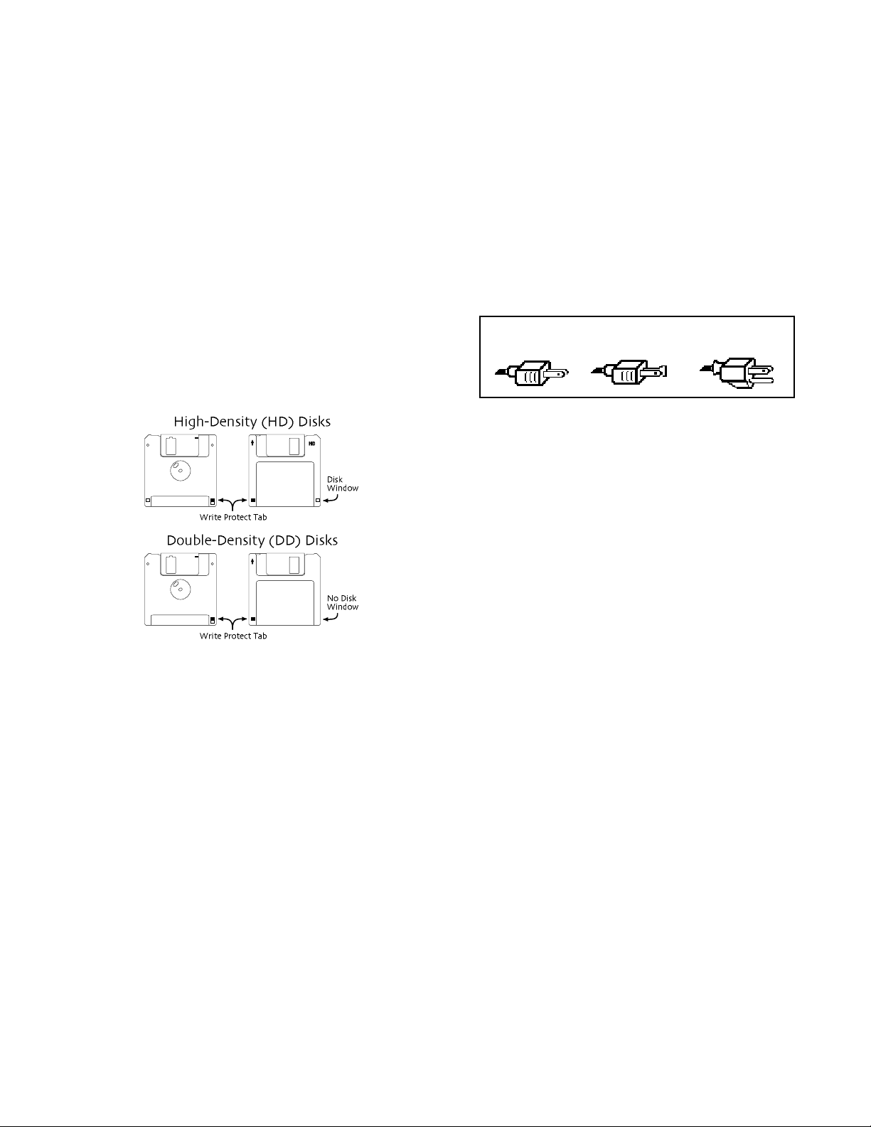
CCCCaaaarrrreeee aaaannnndddd FFFFeeeeeeeeddddiiiinnnngggg ooooffff tttthhhheeee DDDDiiiisssskkkk DDDDrrrriiiivvvvee
The ASR-X ProÕs disk drive is used to store sounds, rhythms, and sequencer
data. This quad-density disk drive will store your data on a high-density
(HD) 3.5Ó micro floppy disk. You can also store data on a DOS-formatted
double-density (DD) 3.5Ó micro floppy disk.
Disks have a sliding write-protection tab so that you can protect your data
against accidental erasure. When the write-protection tab covers the protect
window, you can store information on the disk. Sliding the tab so that the
window is open will protect the disk against being accidentally reformatted
or having files deleted. High density disks can be easily identified because
they have an additional disk window located on the lower right corner of
the disk.
Floppy disks are a magnetic storage medium, and should be treated with
the same care youÕd give important audio tapes. Just as you would use high
quality audio tapes for your important recording needs, we recommend
using high quality floppy disks for your ASR-X Pro. Here are a few DoÕs
and DonÕtÕs concerning disks and the disk drive.
::
DDDDooooÕÕÕÕssss::
¥ Use either high-density (HD) or double-density (DD) 3.5Ó disks. Both
types are available from most computer stores.
¥ Keep your disks and the disk drive clean and free of dust, dirt, liquids,
etc.
¥ Label your disks and keep a record of what is saved on each.
::
DDDDoooonnnnÕÕÕÕttttÕÕÕÕssss::
¥ DonÕt use single-sided (SD) disks. These disks have not passed testing
on both sides. While a single-sided disk might work with the ASR-X
Pro, it is possible that you will eventually lose important data to a
disk error if you try using single-sided disks.
¥ DonÕt put anything other than a disk into the disk drive.
¥ DonÕt transport the unit with a disk in the drive.
¥ DonÕt expose disks to temperature extremes. Temperatures below 50û
F and above 140û F can damage the plastic outer shell.
¥ DonÕt expose your disks to moisture.
¥ DonÕt dry your disks in a microwave oven.
¥ DonÕt subject disks to strong magnetic fields. Exposure to magnetic
energy can permanently damage the information on the disk. Keep
disks away from speaker cabinets, tape decks, power cables, airline x-
ss
ee
ray equipment, power amplifiers, TV sets, and any other sources of
magnetic energy.
¥ DonÕt eject the disk while the drive is operating (i.e., when the disk
drive light is on).
CCCClllleeeeaaaannnn UUUUpppp aaaannnndddd MMMMaaaaiiiinnnntttteeeennnnaaaannnnccccee
Clean the exterior of your ASR-X Pro with a soft, lint-free, dry (or slightly
damp) cloth. You can use a slightly dampened cloth (with a mild neutral
detergent) to remove stubborn dirt, but make sure that the ASR-X Pro is
thoroughly dry before turning on the power. Never use alcohol, benzene,
volatile cleaners, solvents, abrasives, polish or rubbing compounds.
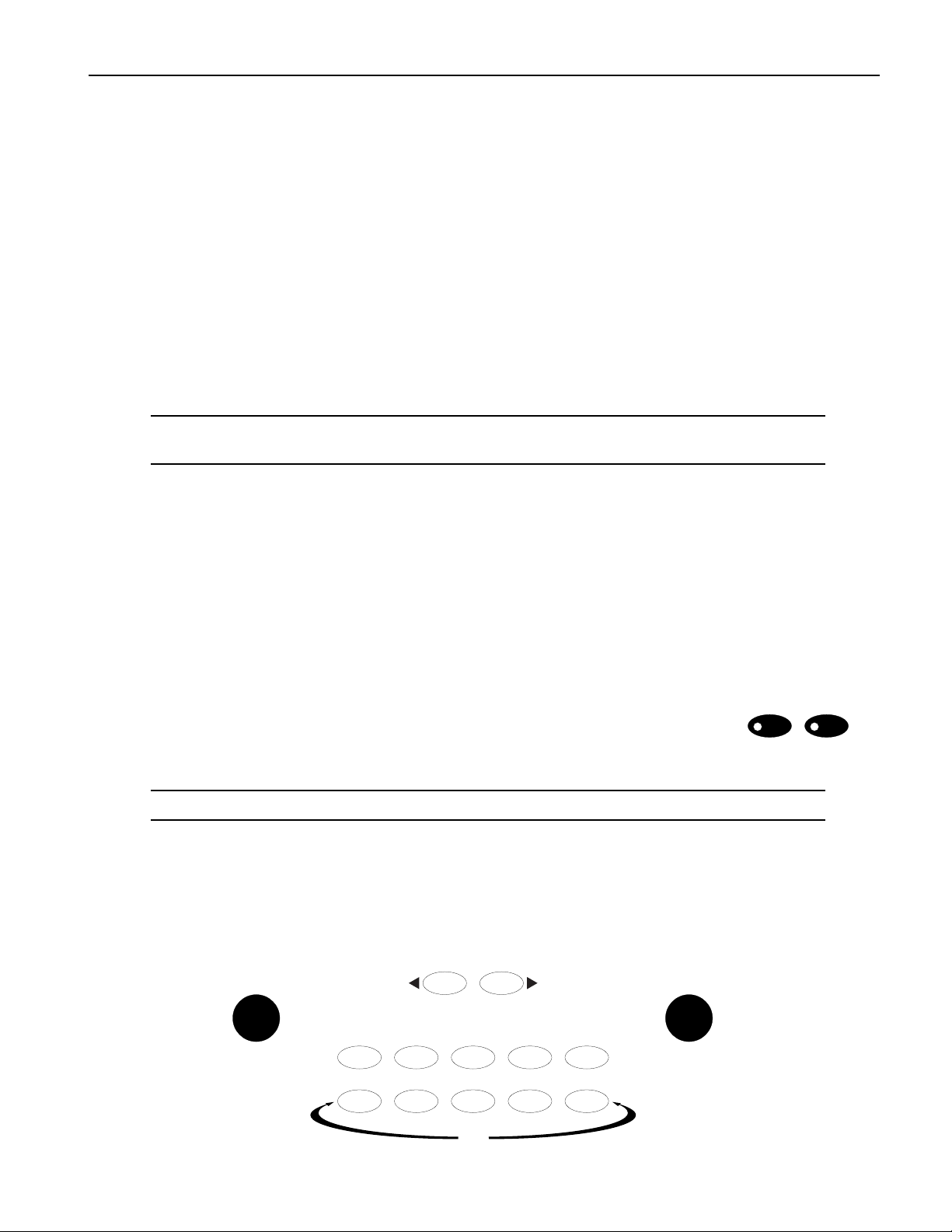
PPPPoooollllaaaarrrriiiizzzzaaaattttiiiioooonnnn aaaannnndddd GGGGrrrroooouuuunnnnddddiiiinnnngg
Like many modern electrical devices, your ENSONIQ product has a threeprong power cord with earth ground to ensure safe operation. Some
products have power cords with only two prongs and no earth ground. To
ensure safe operation, modern products with two-prong power cords have
polarized plugs which can only be inserted into an outlet the proper way.
ee
gg
Three-prong
PolarizedNon-polarized
Some products, such as older guitar amplifiers, do not have polarized plugs
and can be connected to an outlet incorrectly. This may result in dangerous
high voltages on the audio connections, which could cause you physical
harm or damage any properly grounded equipment to which they are
connected, such as your ENSONIQ product.
To avoid shock hazards or equipment damage, we recommend the
following precautions:
¥ If you own equipment with two-pronged power cords, check to see if
they are polarized or non-polarized. You might consider having an
authorized repair station change any non-polarized plugs on your
equipment to polarized plugs to avoid future problems.
¥ Exercise caution when using extension cords or plug adapters. Proper
polarization should always be maintained from the outlet to the plug.
The use of polarized extension cords and adapters is the easiest way
to maintain proper polarity.
¥ Whenever possible, connect all products with grounded power cords
to the same outlet ground. This will ensure a common ground level to
prevent equipment damage and minimize hum in the audio output.
AC outlet testers are available from many electronic supply and hardware
stores. These can be used to check for proper polarity of outlets and cords.
AAAACCCC LLLLiiiinnnneeee CCCCoooonnnnddddiiiittttiiiioooonnnniiiinnnngg
As with any computer device, the ASR-X Pro is sensitive to sharp peaks and
drops in the AC line voltage. Lightning strikes, power drops, or sudden and
erratic surges in the AC line voltage can scramble the internal memory, and
in some cases, damage the unitÕs hardware. Here are a few suggestions to
help guard against such occurrences:
¥ A surge/spike suppressor. A surge/spike suppresser absorbs surges
and protects your gear from all but the most severe over-voltage
conditions. You can get multi-outlet power strips with built-in
surge/spike suppressers for little more than the cost of unprotected
power strips, so using one is a good investment for all your electronic
equipment.
¥ A line conditioner. This is the best, but by far the more expensive way
to protect your gear. In addition to protecting against surges and
spikes, a line conditioner guards the equipment against excessively
high or low line voltages. If you use the ASR-X Pro in lots of different
locations with varying or unknown AC line conditions, you might
consider investing in a line conditioner.
gg
with earth ground
Page 6

Page 7

Table of Contents
TTTTaaaabbbblllleeee ooooffff CCCCoooonnnntttteeeennnnttttss
TTTTuuuuttttoooorrrriiiiaaaallll 11
LLLLiiiisssstttt ooooffff RRRROOOOMMMM SSSSoooouuuunnnnddddssss 222233
IIIInnnnsssseeeerrrrtttt EEEEffffffffeeeecccctttt PPPPaaaarrrraaaammmmeeeetttteeeerrrrssss 222277
11
ss
33
77
ENSONIQ ASR-X Pro UserÕs Guide
Page 8

Page 9
Tutorial
TTTTuuuuttttoooorrrriiiiaaaall
IIIInnnnttttrrrroooodddduuuuccccttttiiiioooonn
Welcome to the ASR-X Pro UserÕs Guide, and congratulations on your purchase of the ENSONIQ ASR-X
Pro. This book contains a step-by-step tour of the major features of the ASR-X Pro. For more detailed
information on the topics discussedÑand moreÑsee the ASR-X Pro Reference Manual.
The first part of the UserÕs Guide is structured as a tutorial, meant to be read and followed in the order in
which itÕs presented. This approach will allow you to become familiar with ASR-X Pro concepts and
procedures one at a time, and will let you build up your understanding ofÑand comfort withÑthe way
the ASR-X Pro works. The tutorial will only take about a half hour to complete. Along the way, youÕll get
a sense of how much fun it is to create music on your new ASR-X Pro. The remainder of the UserÕs Guide
contains a list of the sounds built into your ASR-X Pro, and a list of its insert effects and their parameters.
NNNNooootttteeee:::: At the end of various sections of the tutorial, youÕll see a ÒBefore proceeding...Ó section. The
instructions in each these sections help set up the tutorials that follow.
ll
nn
WWWWhhhhaaaatttt EEEEllllsssseeee iiiissss iiiinnnn tttthhhheeee AAAASSSSRRRR----XXXX PPPPrrrroooo BBBBooooxxxx??
The following items are included with every ASR-X Pro shipped from the ENSONIQ factory:
¥ ENSONIQ X-Audio Sampling CD ¥ ENSONIQ ASR-X Pro UserÕs Guide
Volume 1ÑProducersÕ Mix ¥ ENSONIQ ASR-X Pro Reference Manual
¥ hex wrench ¥ AC power cable
??
GGGGeeeettttttttiiiinnnngggg AAAArrrroooouuuunnnndddd oooonnnn tttthhhheeee AAAASSSSRRRR----XXXX PPPPrrrroo
TTTThhhheeee DDDDiiiissssppppllllaaaayyyy aaaannnndddd YYYYeeeessss////NNNNoooo BBBBuuuuttttttttoooonnnnss
The display located in the center of the ASR-X Pro front panel will always tell you
what you need to know as you do different things on the ASR-X Pro. Many ASR-X
Pro procedures will be presented as questions that you can answer by pressing the
No or Yes button.
TTTTiiiipppp:::: When a question is being asked, the LEDs in the No and Yes buttons will flash.
Some activities involve a series of parameters and/or procedures. In such cases, youÕll begin by
answering ÒYesÓ to a top-level question. From there youÕll encounter parameters and/or further
questions presented on sub-displays that relate to what youÕre doing. To exit back out to the top level of
the ASR-X Pro, you can press the Exit/No button.
TTTThhhheeee KKKKnnnnoooobbbbss
ss
Parameter Value
Sound
Type
0
oo
ss
Select Track
116
MIDI Channel
Essentials
1
23
4
Sound
Name
Exit Enter
No Yes
567
Demo
ENSONIQ ASR-X Pro UserÕs Guide 1
89
Page 10

Tutorial
Below the display in the center of the front panel are two knobs used during most ASR-X Pro activities.
These knobs are known by two different sets of names, since they serve two general purposes.
When youÕre selecting sounds for tracks or for pads in the ASR-X Pro, the central knobs should be
thought of as the ÒSound TypeÓ and ÒSound NameÓ knobs.
Sound
Type
For every other activity, the knobs will be referred to as the ÒParameter knobÓ and the ÒValue knob.Ó
Parameter Value
Both sets of names are printed on the front panel, as you can see.
SSSSoooommmmeeee AAAASSSSRRRR----XXXX PPPPrrrroooo TTTTeeeerrrrmmmmssss YYYYoooouuuu RRRReeeeaaaallllllllyyyy NNNNeeeeeeeedddd ttttoooo KKKKnnnnooooww
ItÕs important that you understand the meaning of these terms as you use the ASR-X Pro:
¥ parameterÑThis is any characteristic of the ASR-X Pro software that can be changed.
¥ valueÑThis is the setting of a parameter.
¥ selectÑThis is the act of choosing a sound for playing or recording, or choosing a parameter to be
edited.
¥ standard soundÑA sound is a program that plays one or more digital audio recordings arranged in
layers. The recordings, or waves, can be data permanently stored in the ASR-X ProÕs ROM (for Òreadonly memoryÓ), or something youÕve sampled or loaded into the ASR-X Pro. Standard sounds based
on ROM waves can have up to 16 layers; sounds that play sampled waves use one layer for mono
waves, or two layers for stereo waves.
¥ kit soundÑA kit is a sound in which each of its 64 notes can play a different standard sound. Since
the ASR-X Pro is designed for beats and loops, kit sounds are its most potent sounds.
ww
Sound
Name
TTTTiiiipppp:::: See Chapter 3 of the ASR-X Pro Reference Manual to learn more about standard and kit
sounds.
GGGGeeeettttttttiiiinnnngggg RRRReeeeaaaaddddyyyy ttttoooo GGGGoo
MMMMaaaakkkkiiiinnnngggg CCCCoooonnnnnnnneeeeccccttttiiiioooonnnnss
There are a few types of connections youÕll want to make as you set up the ASR-X Pro Ñall of the jacks
necessary for these connections are located on the rear panel of the ASR-X Pro. YouÕll want to set up:
¥ a way of listening to the ASR-X ProÑYou can connect the ASR-X
ProÕs Left and Right Main Out jacks to a mixer, amplifier or stereo
system. If youÕd like to use the ASR-X Pro in mono, connect only the
Left or Right Main Out jack to your mixer or amplifier, and make
sure nothing is plugged into the other Main Out jack. If youÕd rather
listen to the ASR-X Pro through headphones, you can plug yours in
to the ASR-X ProÕs Phones jackÑyour headphones will need to have
a 1/4Ó stereo plug or adapter to work correctly with the Phones jack.
2 ENSONIQ ASR-X Pro UserÕs Guide
oo
ss
Main Out
Right
Mono Mono
Left
Phones
Page 11
Tutorial
WWWWaaaarrrrnnnniiiinnnngggg:::: If you connect the Main Outs to a stereo system, set your ASR-X Pro Volume level
carefully, or you risk damaging components of your stereo. See ÒSetting LevelsÓ below.
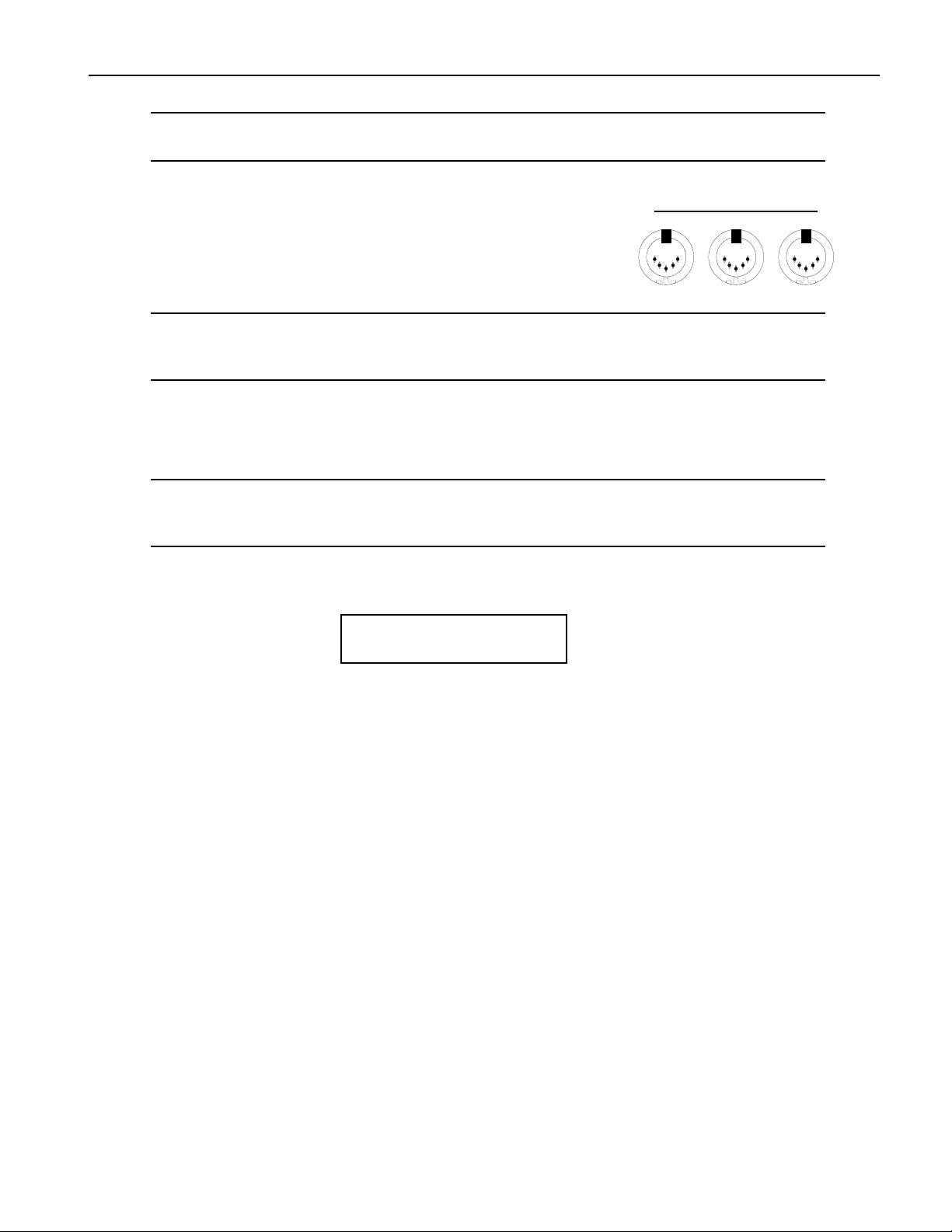
¥ If you plan to use any external MIDI devices with the ASR-X ProÑsuch as a keyboard, sequencer or
computerÑyouÕll need to connect:
¥ the MIDI In of the ASR-X Pro to the MIDI Out of the
external device.
¥ the MIDI OUT of the ASR-X Pro to the MIDI In of the
external device.
TTTTiiiipppp:::: YouÕll be able to verify that your external MIDI device is properly connect to the ASR-X Pro
by transmitting some MIDI data to the ASR-X Pro Ñwhen the ASR-X Pro receives the data, its
front-panel MIDI LED will light.
¥ AC power for the ASR-X ProÑby connecting one end of the supplied power cord to the AC Line
jack on the back of the ASR-X Pro, and the other end to a grounded AC outlet.
MIDI
InOutThru
PPPPoooowwwweeeerrrriiiinnnngggg UUUUpp
WWWWaaaarrrrnnnniiiinnnngggg:::: Before powering up your ASR-X Pro for the first time, turn its front-panel Volume knob
all the way down (counter-clockwise) before turning it on. This will help make sure that youÕve
set safe levels for all of your equipment before you make any sound on the ASR-X Pro.
To power up the ASR-X Pro, press in the top of its rear-panel power switch. When you do so, the ASR-X
Pro will start up and display:
pp
ENSONIQ ASR-X PRO
Resampler w/ Effects
SSSSeeeettttttttiiiinnnngggg LLLLeeeevvvveeeellllss
WWWWhhhheeeennnn CCCCoooonnnnnnnneeeecccctttteeeedddd ttttoooo aaaa MMMMiiiixxxxeeeerrrr oooorrrr AAAAmmmmpppplllliiiiffffiiiieeeerr
The ASR-X Pro will produce its best sound when its volume knob is turned all the way up, so the best
way to set up your ASR-X Pro levels is to:
1. Turn the volume of the channels to which youÕve connected the ASR-X Pro all the way down. If
youÕre connected to a mixer, turn down the channel preamps as well.
2. Turn the ASR-X Pro Volume knob all the way up.
3. Play the ASR-X Pro pads with a good amount of force.
4. Set the levels on your mixer or amplifier to a workable setting.
ss
rr
WWWWhhhheeeennnn CCCCoooonnnnnnnneeeecccctttteeeedddd ttttoooo aaaa HHHHoooommmmeeee SSSStttteeeerrrreeeeoooo SSSSyyyysssstttteeeemm
Since the dynamic range produced by the ASR-X Pro is greater than that of a CD, record or cassette, set
your levels carefully:
1. Set the stereo to your normal listening level.
2. Play the ASR-X Pro pads with a good amount of force.
3. While playing, slowly bring up the setting of the ASR-X Pro volume knob to an acceptable level that
doesnÕt cause your stereo to distort.
WWWWhhhheeeennnn UUUUssssiiiinnnngggg HHHHeeeeaaaaddddpppphhhhoooonnnneeeess
1. Play the ASR-X Pro pads with a good amount of force.
2. Slowly bring up the setting of the ASR-X Pro volume knob to a comfortable listening level.
ENSONIQ ASR-X Pro UserÕs Guide 3
ss
mm
Page 12
Tutorial
PPPPllllaaaayyyyiiiinnnngggg tttthhhheeee AAAASSSSRRRR----XXXX PPPPrrrroooo DDDDeeeemmmmooooss
The ASR-X Pro contains demos to give you an idea of what it sounds like. To play the main demo:
1. Locate the Essentials buttons on the ASR-X Pro front panel.
0
567
2. Hold down the Essentials button with Ò5Ó printed beneath it.
567
3. While still holding the button down, press the Essentials button with Ò9Ó printed beneath it.
567
4. Release both buttons.
The display shows:
ss
1
Essentials
23
Demo
Demo
Demo
4
89
89
89
5. Press the Enter/Yes button to hear the demo.
6. To stop the demo, press the Track Sound button in the center of the ASR-X Pro front panel.
NNNNooootttteeee:::: You can actually press any button to stop the demoÑthe Track Sound button was specified
for the purposes of this tutorial.
7. To listen to any of the other built-in demos, turn the Parameter knob to select a demo category, the
Value knob to pick an individual demo from the selected category, and press the Yes button.
SSSSeeeelllleeeeccccttttiiiinnnngggg TTTTrrrraaaacccckkkkss
The ASR-X Pro is organized into a framework of 16 tracks that play an important role in the ASR-X Pro:
¥ When youÕre playing sounds or sampling/resampling in the ASR-X Pro, you can think of each track
as being a container for the sound with which youÕre working.
¥ When youÕre recordingÑor sequencingÑeach track contains a recorded performance, as well as the
sound that plays it.
¥ The ASR-X Pro is a multi-timbral MIDI receiverÑthe 16 tracks correspond to MIDI channels 1-16.
Each track receives MIDI data on its like-numbered channel. You can play a trackÕs sound or record
on a track via MIDI at any time.
¥ Each track transmits MIDI data on its like-numbered channel when it uses a MIDI-OUT sound.
Start demo playback?
MAINDEMO: Internal
ss
Whenever you do anything in the ASR-X Pro, youÕre always on one or another of these tracks, which is
referred to as Òthe currently selected track.Ó The ASR-X Pro display tells you which track is currently
selectedÑthat is, which track youÕre on.
4 ENSONIQ ASR-X Pro UserÕs Guide
Page 13
Since youÕve just powered up and played the demo, youÕre on Track 1:
This shows youÕre on Track 1
m
¦01 ROM10:000
DEMO-SND: Gizmo Kit
i
The sound on Track 1
TTTTiiiipppp:::: The currently selected track is shown on the display during many ASR-X Pro activities.
Tutorial
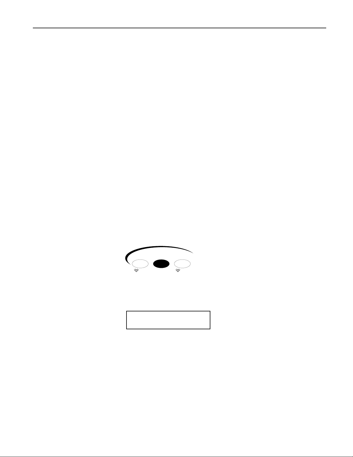
TTTToooo SSSSeeeelllleeeecccctttt OOOOnnnneeee ooooffff tttthhhheeee 11116666 TTTTrrrraaaacccckkkkss
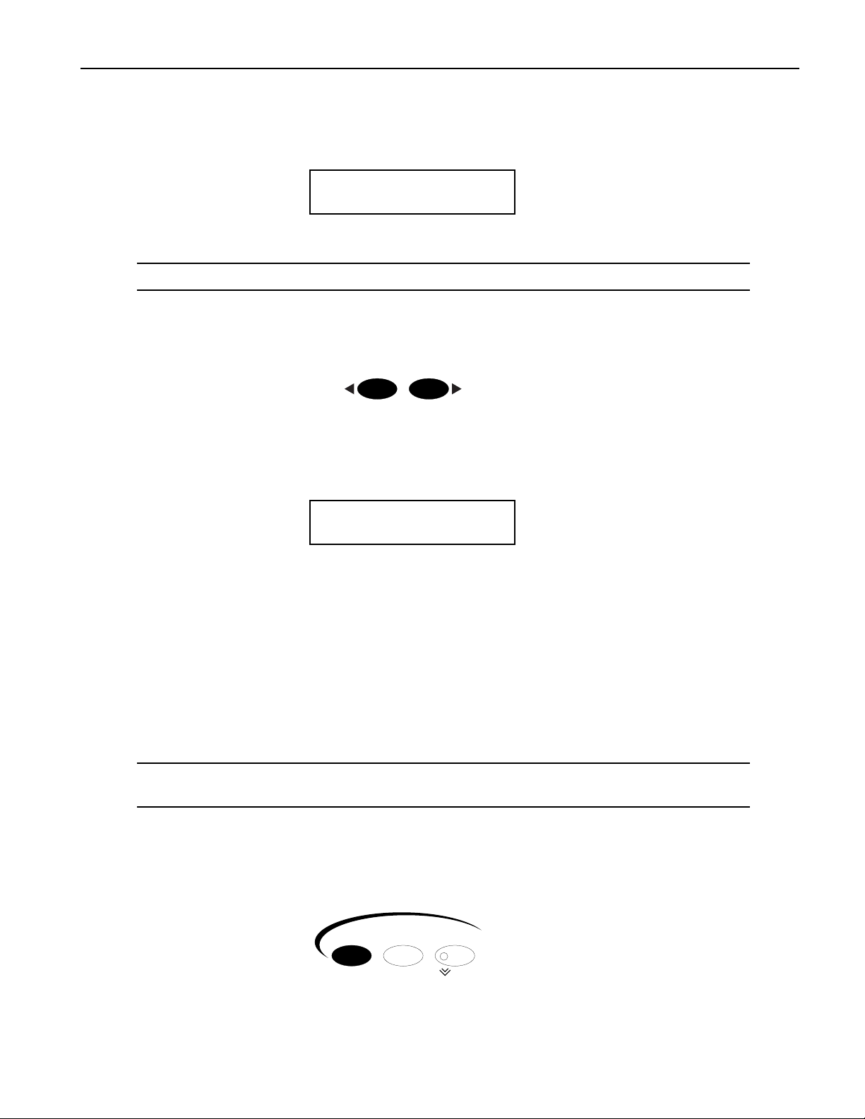
1. Locate the Select Track buttons.
2. Press the right-hand Select Track button once. The display shows that youÕve just selected the next
track, Track 2.
This shows youÕre now on Track 2
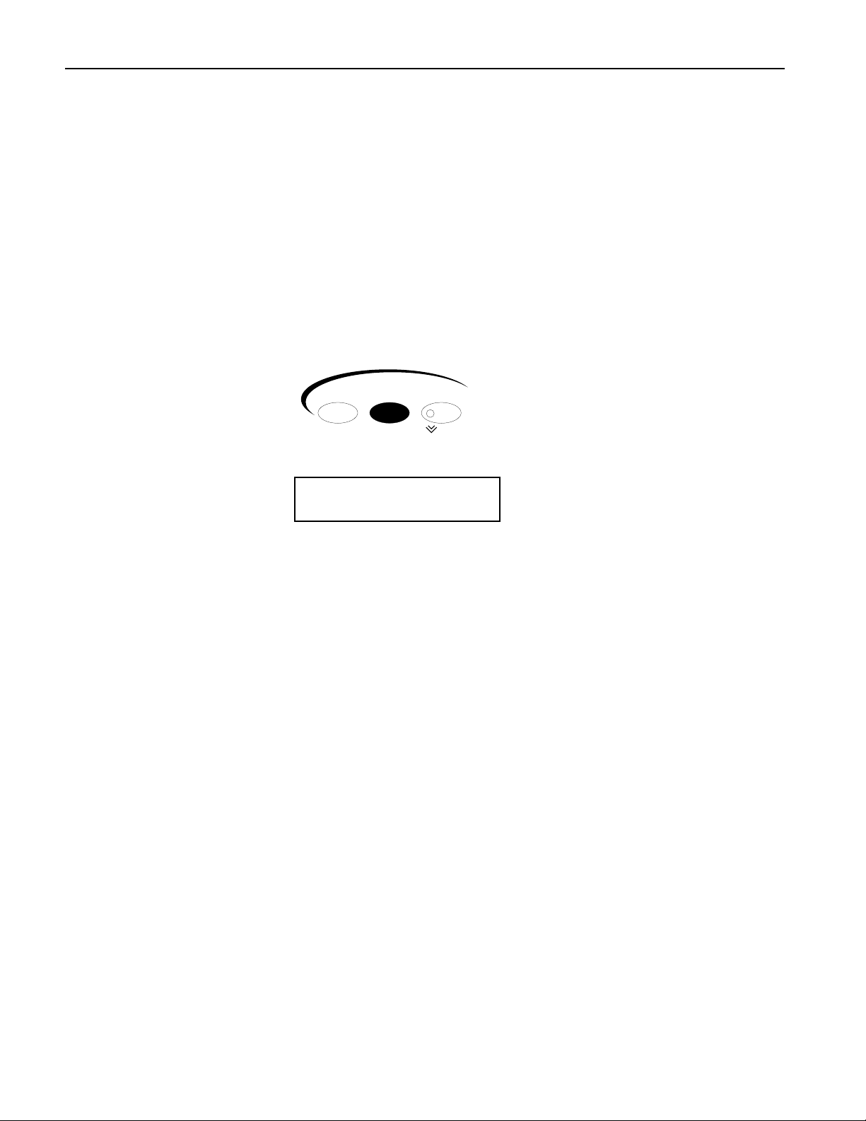
Higher-numbered tracks are selected by pressing the right-hand Select Track button, while lower
numbered tracks are selected by pressing the left Select Track button.
3. Press the left Select Track button to go back to Track 1.
SSSSeeeelllleeeeccccttttiiiinnnngggg TTTTrrrraaaacccckkkk SSSSoooouuuunnnnddddss
Each track can play any of the sounds in the ASR-X Pro. Finding just the right sound is simple, thanks to
the ASR-X ProÕs SoundFinderª feature. With SoundFinder, you select the type of sound you want, and
then choose a specific sound of that type.
ss
ss
Select Track
116
MIDI Channel
m
¦02 ROM09:011
BASS-SYN:Snot-T-Bass
i
The sound on Track 2
TTTTiiiipppp:::: For a list of SoundFinder categories, see Chapter 9 of the ASR-X Pro Reference Manual. For a
list of all of the ASR-X ProÕs built-in sounds, see ÒList of ROM SoundsÓ later in the UserÕs Guide.
TTTToooo SSSSeeeelllleeeecccctttt aaaa SSSSoooouuuunnnndddd ffffoooorrrr aaaa TTTTrrrraaaacccckk
1. Check the displayÕs upper left-hand corner to make sure that youÕve got the desired track
selectedÑfor this tutorial, youÕll use Track 1.
2. Press the Track Sound button.
(Later in this section you'll learn why "DEMO-SND" just changed to "DRUM-KIT" on the display.)
ENSONIQ ASR-X Pro UserÕs Guide 5
kk
Sound Edit Mute
Track
Mix / FX Bus
Solo
Page 14

Tutorial
3. Turn the Sound Type knob to view the SoundFinder categories that are currently available.
SoundFinder categories are shown in the lower-left corner of the display. (When there are no sounds
in memory of a particular type, its SoundFinder category isnÕt shown. )
¦01 ROM08:000
PERCSOLO: Thump Kick
i
The currently selected SoundFinder type
4. Select the DRUM-KIT SoundFinder type.
5. Turn the Sound Name knob to view the various drum kits in the DRUM-KIT SoundFinder category.
¦01 ROM10:005
DRUM-KIT:OlÕSkoolKit
i
As you turn the Sound Name knob, the sounds in the selected SoundFinder category are displayed
You can also select sounds using the Essentials buttons. Each button can be pressed to instantly
place a favorite sound onto the current track. To learn more about the Essentials buttons, see
Chapter 2 of the ASR-X Pro Reference Manual
6. Press some of the Essentials buttons to see how they work, and to check out the sounds that
ENSONIQ assigned to the buttons at the factory. You can also press any upper Essentials button and
the button just beneath itÑan additional five sounds can be accessed in this manner.
7. Press the Essentials button with the Ò2Ó beneath it to select the sound HeavyDrmKit. The display
provides information about the sound youÕve selected:
The track youÕre on The soundÕs bank number The soundÕs program number
The selected SoundFinder type The selected sound
Sounds are stored in groups called banks. Each bank can contain up to 127 sounds, each of which is
numbered. This system allows you to select sounds via MIDI, since each bankÕs number is also its MIDI
Bank Select number, and each soundÕs program number is also its MIDI Program Change number. By
sending the correct MIDI Bank select and Program Change values on a trackÕs MIDI channel, you can
select its sound from an external MIDI device.
TTTTiiiipppp:::: Each sound can be found in the bank in which it's stored and in an instrument category. You
can press the Track Sound button to toggle between these. In Step 1, "DEMO-SND" changed to
"DRUM-KIT" on the display when we pressed Track Sound for the second time in this tutorial.
PPPPllllaaaayyyyiiiinnnngggg wwwwiiiitttthhhh tttthhhheeee PPPPaaaaddddss
Now that youÕve selected HeavyDrmKit for Track 1, why not play it? The pads on the ASR-X Pro are a
keyboard of sorts that plays the sound youÕve chosenÑitÕs a percussion-oriented keyboard perfect for a
groovestation like the ASR-X Pro. Bang out a few notes to hear some of the bass drum and snare sounds
in HeavyDrmKit. Since itÕs a kit sound, each pad can play a different standard sound.
ss
lmn
¦01 ROM10:002
DRUM-KIT:HeavyDrmKit
ii
ASR-X Pro sounds cover the entire pitch range typical of any modern MIDI instrument. The 13 ASR-X
Pro pads play a section of a sound at a timeÑan octave-plus-one-noteÕs worthÑin this case, the bass
drum and snare range of HeavyDrmKit. To the left of the pads are the Octave Buttons. These are used for
re-aiming the pads at different octaves within the currently selected sound.
6 ENSONIQ ASR-X Pro UserÕs Guide
Page 15
Tutorial
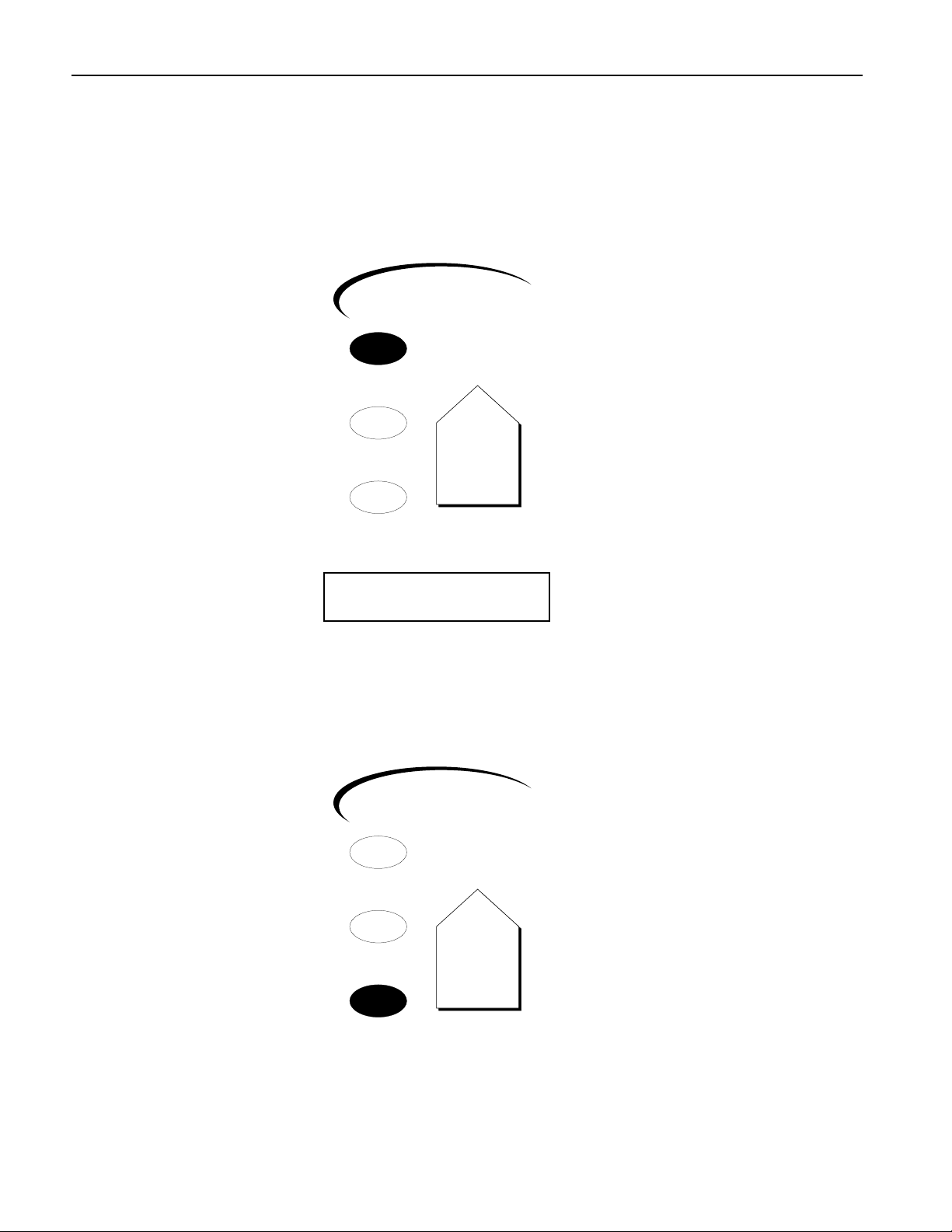
TTTToooo CCCChhhhaaaannnnggggeeee tttthhhheeee OOOOccccttttaaaavvvveeee PPPPllllaaaayyyyeeeedddd bbbbyyyy tttthhhheeee PPPPaaaaddddss
1. Locate the Octave Transpose buttons.
Octave Transpose
2. Press the right-hand Octave Transpose button once. The display briefly shows:
ss
¦01 ROM10:002
Pad Xpose=0oct C2-C3
ii
The number of the octave being played by the pads The note range being played
The Octave Transpose display shows the octave the pads are currently playing. The pads can play
five different octaves, each of which has been assigned a number as shown below (Middle C is C4):
¥ Octave 0 plays C2-C3 ¥ Octave 2 plays C4-C5 ¥ Octave 4 plays C6-C7
¥ Octave 1 plays C3-C4 ¥ Octave 3 plays C5-C6
3. Tap the right-hand Octave Transpose button twice to set the pads to play Octave 1. The first tap
takes you to the Octave Transpose display, and the second tap raises the octave setting by one.
TTTTiiiipppp:::: You can also select an octave by pressing either of the Octave Transpose buttons and turning
the Value knob.
4. Play the padsÑnow youÕre playing the sounds contained in the second octave of HeavyDrmKit.
5. Use the Octave buttons to find the other sounds in HeavyDrmKit.
BBBBeeeeffffoooorrrreeee PPPPrrrroooocccceeeeeeeeddddiiiinnnngggg..........
1. Press the left Octave Transpose button to bring the pads down to Octave 0.
NNNNooootttteeee:::: If you see ÒKit MapperÓ on the display, press the right-hand Octave Transpose button once.
The Kit Mapper is described in Chapter 3 of the ASR-X Pro Reference Manual.
UUUUssssiiiinnnngggg tttthhhheeee PPPPaaaattttcccchhhh SSSSeeeelllleeeecccctttt BBBBuuuuttttttttoooonnnnss
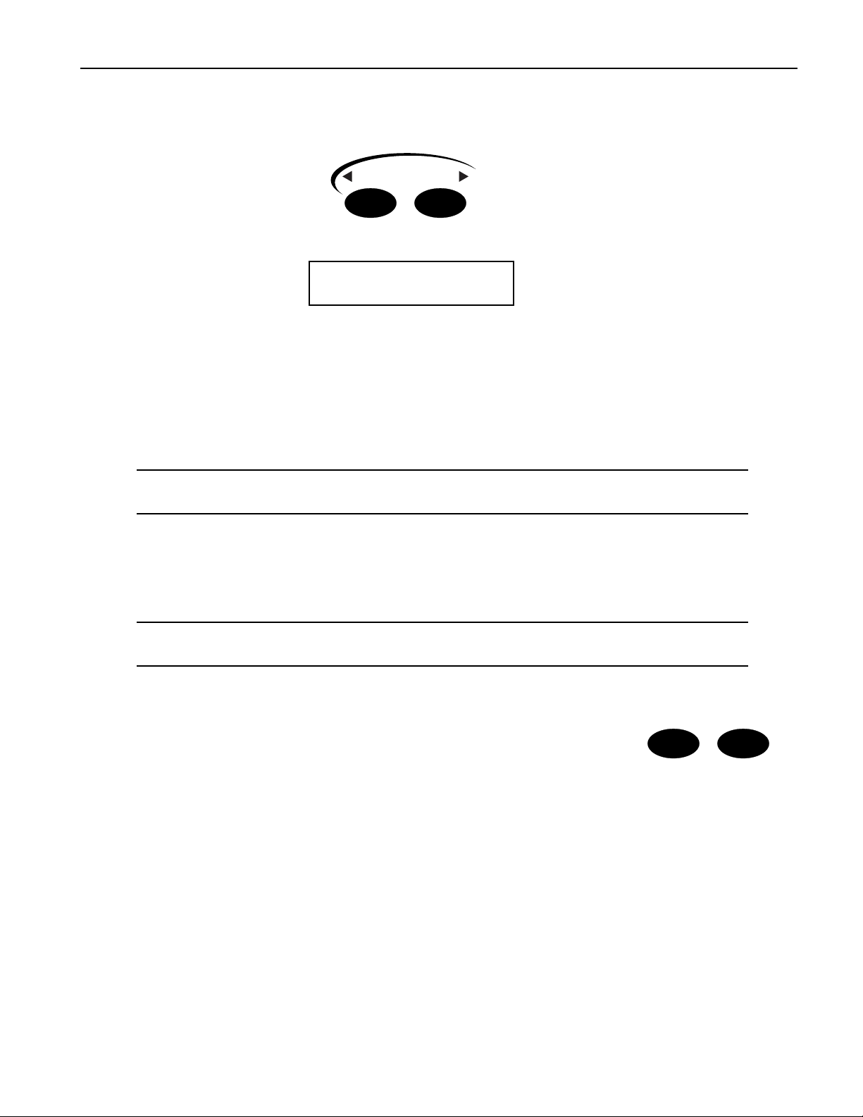
The Patch Select buttons call up variations of the currently selected sound.
Each sound is made up of layers of waves, and the Patch Select buttons are
programmed to turn layers or groups of layers on and off (see Chapter 3 in the
ASR-X Pro Reference Manual for more on layers). Depending on the nature of
the sound, this can lead to subtle or radical changes in the sound.
Patch Select buttons are able to operate in a couple of different ways. The default setting is for them to act
as switches that only work as long as theyÕre physically being held down. There are four possible
positions for the Patch Select buttons:
¥ left Patch Select button pressed ¥ both Patch Select buttons pressed
¥ right Patch Select button pressed ¥ neither Patch select button pressed
The Patch Select buttons can also be set to Òstick,Ó as described in Chapter 7 of the ASR-X Pro Reference
Manual.
..
ss
Patch Selects™
As part of the demonstration of the Patch Select buttons, letÕs select a synthesizer bass sound for Track
2ÑweÕll need it later on anyway.
ENSONIQ ASR-X Pro UserÕs Guide 7
Page 16

Tutorial
1. Press the right-hand Select Track button once to select Track 2.
2. Using the Sound Name knobs, select the sound BuzzSawBassÑsince the BASS-SYN category was
already selected, you didnÕt have to turn the Sound Type knob to select a SoundFinder category.
3. Play a few notes of BuzzSawBass to get an idea of its sound with no Patch Select buttons pressed.
4. Play the padsÑwith a standard sound such as BuzzSawBass, all the pads play the same basic sound
at different pitches.
BuzzSawBass is one of the sounds built into the ASR-X ProÕs permanent ROM. Since ROM sounds
can contain up to 16 layers of waves, the Patch Select buttons are most useful when used with these
sounds.
5. Hold down either of the Patch Select buttons and play some notes on the padsÑhear how that
sound has changed? You can release the button to return BuzzSawBass to its original sound.
6. Try the other Patch Select positions with BuzzSawBass.
TTTTiiiipppp:::: Patch Select button-presses will be recorded if they occur during the recording of a sequence
track. TheyÕre also transmitted via MIDI so that they can be used for controlling other ENSONIQ
products that use Patch Select buttons, and so that they can be recorded in an external sequencer.
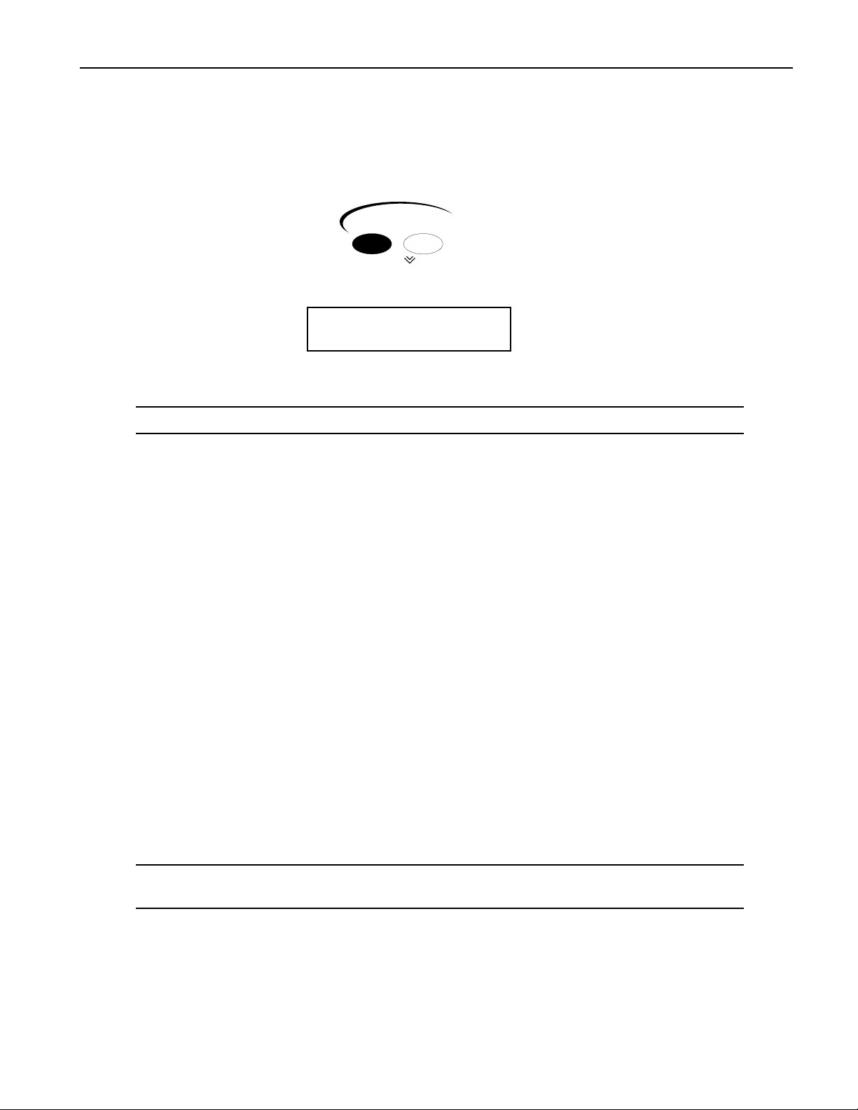
BBBBeeeeffffoooorrrreeee PPPPrrrroooocccceeeeeeeeddddiiiinnnngggg..........
1. Press the left Select Track button to return to Track 1.
SSSSeeeeqqqquuuueeeennnncccciiiinnnngggg iiiinnnn tttthhhheeee AAAASSSSRRRR----XXXX PPPPrrrroo
The ASR-X Pro contains a recording device called a sequencer that is both powerful and easy to use. A
sequencer records the music you play on each of its 16 tracks. The music is recorded on each track as
MIDI data, and is therefore highly editable. Each segment of music you record is called a sequence. There
is always a sequence selected in the ASR-X ProÑeven when you havenÕt yet recorded anythingÑand the
track that youÕre on is in that sequence.
TTTToooo RRRReeeeccccoooorrrrdddd aaaa SSSSeeeeqqqquuuueeeennnncccceeee TTTTrrrraaaacccckk
TTTTiiiipppp:::: Read through Steps 1 through 4 once before actually doing them so that recording doesnÕt
sneak up on you before youÕre ready.
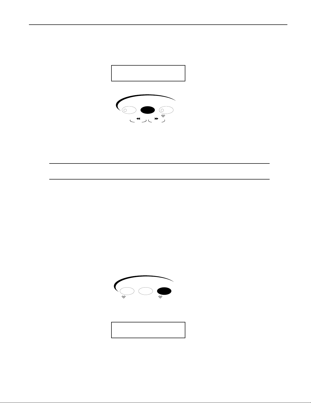
1. Press and hold down the Transport Record button.
2. While still holding the Record button, press the Play button, and
then release both buttons. The Record and Play button LEDs light to
show youÕre recording.
The sequencer begins counting off four beats before recording begins.
The display shows the countoff in negative numbers in the upper-right corner of the displayÑwhen
the numbers get to 0, recording actually starts.
..
oo
kk
Transport
Record Stop Play
Scoop Locate Top
Rew
F Fwd
The numbers count up to the first beat of actual recording
m
¦01 -1 .01
DRUM-KIT:HeavyDrmKit
TTTTiiiipppp:::: This countoff can be customized or turned off. See Chapter 6 in the ASR-X Pro Reference
Manual.
YouÕll be recording two measures. On the first and third beats, play the lowest pad, a bass drum
sound. On the second and fourth beats, play the highest pad, a snare drum sound.
8 ENSONIQ ASR-X Pro UserÕs Guide
Page 17
Tutorial
3. At the first beat after the countoff, play the pads as described above. The display will show you
where you are in each measure, in bars and beats.
This shows the bar youÕre in This show which beat youÕre on
mm
¦01 1 .04
DRUM-KIT:HeavyDrmKit
4. At the end of the second measure, press the Stop button.
Transport
Record Stop Play
Scoop Locate Top
Rew
YouÕve just recorded your first track in your first sequence.
F Fwd
TTTToooo PPPPllllaaaayyyy BBBBaaaacccckkkk aaaa SSSSeeeeqqqquuuueeeennnncccceeee TTTTrrrraaaacccckk
1. Hold down the Record button, press the Stop button, and then release both buttons to rewind to the
top of the sequence.
TTTTiiiipppp:::: The Transport buttons perform many tasksÑsee Chapter 6 in the ASR-X Pro Reference
Manual to learn more.
2. Press the Play button.
The track youÕve just recorded plays backÑthe sequence loops, playing your recording over and
over (this default sequence setting can be changed; see Chapter 6 in the ASR-X Pro Reference
Manual).
3. Press the Stop button to end playback.
oo
UUUUnnnnddddoo
For situations in which youÕve recorded something youÕd like to get rid of, or when youÕve done
something to a track that you wish you hadnÕt done, the ASR-X Pro provides a handy Undo feature. As
long as you havenÕt yet recorded other tracks or performed other procedures, you can undo whatever
youÕve just done to a track.
TTTToooo UUUUnnnnddddoooo aaaa TTTTrrrraaaacccckk
1. Double-click the Sequence Process button.
kk
kk
Sequence
Select Edit Process
New Tap / Tempo Undo
The display shows:
The default name of the sequence youÕve been recording The location at which you stopped playback
mn
SEQ00001 1.04
Undo track 1?
The No/Yes LEDs flash to indicate that youÕre being asked a question.
2. If youÕd like to undo your recording and try again, press the Yes button and repeat the steps in ÒTo
Record a Sequence TrackÓ above. Press the No button if you're satisfied with your performance.
ENSONIQ ASR-X Pro UserÕs Guide 9
Page 18

Tutorial
CCCCoooorrrrrrrreeeeccccttttiiiinnnngggg tttthhhheeee TTTTiiiimmmmiiiinnnngggg ooooffff aaaa PPPPeeeerrrrffffoooorrrrmmmmaaaannnnccccee
A sequencer such as the one in the ASR-X Pro can correct timing inconsistencies in a recorded
performanceÑthis process is called quantizing. The ASR-X Pro offers a sophisticated set of quantizing
tools, as well as quantizing templates, in which common types of quantization are already preprogrammed, and that can hold your own favorite quantization settings.
TTTToooo QQQQuuuuaaaannnnttttiiiizzzzeeee aaaa TTTTrrrraaaacccckk
1. WeÕll be quantizing the just-recorded Track 1, which is therefore already selected. Normally,
however, you'll want to make sure that the track you want to quantize is selected before proceeding.
2. Press the Sequence Process button. The display shows:
kk
ee
SEQ00001 1.01
Undo track 1?
In this case, you donÕt want to undo the track, so donÕt press the Yes button. The Undo function is
only one of the track and sequence operations accessed by pressing the Sequence Process button.
3. Turn the Parameter knob clockwise until the display shows:
SEQ00001 1.01
Quantize track 1?
4. Press the Yes button. The display now shows:
Quantize track 1?
Template=Strict 1/16
This display is presenting you one of the pre-programmed quantizing templates. However, the track
youÕve recorded contains 1/4 notes, not 1/16th notes.
5. Turn the Value knob counter-clockwise to select the Strict 1/4 template.
6. Press the Yes button.
7. Play back your trackÑthe timing of the quarter notes in your track is now perfect.
8. Press the Stop button to end playback.
TTTTiiiipppp:::: To learn more about quantizing, see Chapter 6 of the ASR-X Pro Reference Manual.
AAAAddddddddiiiinnnngggg ttttoooo aaaannnn AAAAllllrrrreeeeaaaaddddyyyy----RRRReeeeccccoooorrrrddddeeeedddd TTTTrrrraaaacccckk
The ASR-X Pro sequencer provides a variety of recording modes, described fully in Chapter 6 of the ASRX Pro Reference Manual. These modes change the way in which the sequencer records what you play. In:
¥ Replace mode, what you record replaces anything already on the track.
¥ Add mode, what you record is added to whatÕs already on the track. In this way, you can build up
complex recordings, an element at a time.
¥ Step mode, you can enter notes or chords one at a time with the sequencer at rest.
¥ Track Mix allows you to record volume, panning and other track setting changes on a track.
¥ Final Mix lets you to record whole-sequence volume changesÑsuch as fade-outsÑ and tempo
changes.
Since youÕre in Add mode (itÕs the default setting), you can now add hihat 1/8th notes to your track.
1. Pressing the right-hand Octave Transpose button twice to aim the pads at HeavyDrmKitÕs second
octave. Play the pads to locate a hihat sound you like.
2. Press the Record and Stop buttons to return to the beginning of the sequence.
3. Hold down the Record button, press Play and release both buttons when the countoff begins.
kk
10 ENSONIQ ASR-X Pro UserÕs Guide
Page 19
Tutorial
4. Record 1/8th notes on the hihat to accompany the two measures of bass drum and snare.
5. Press the Stop button at the end of the second barÑin Add mode, recording continues until you
press the Stop button.
6. Play back your track to hear the bass drum, snare and hihat playing together.
7. If youÕd like to redo the hihat, double-click the Sequence Process button, undo the track, and then
record it again.
8. Correct the hihatÕs timing by repeating the steps in "Correcting the Timing of a Performance." YouÕll
want to select the Strict 1/8th template this time, since you donÕt want your hihat 1/8th notes turned
into 1/4 notes.
BBBBeeeeffffoooorrrreeee PPPPrrrroooocccceeeeeeeeddddiiiinnnngggg..........
1. Press the left Octave Transpose button twice to re-direct the pads back to the lowest octave.
RRRReeeeccccoooorrrrddddiiiinnnngggg AAAAnnnnooootttthhhheeeerrrr TTTTrrrraaaacccckk
LetÕs record synth bass quarter notes on Track 2 to accompany the drums on Track 1. This time, however,
donÕt record any notes during the first measureÑwait until Bar 2 to begin playing. You can use any of the
pads to play your quarter notes.
1. Press the right-hand Select Track button to select Track 2.
2. Hold down Record, press Stop and let go of both buttons to make sure youÕre at the beginning of the
sequence.
3. Record your bass part using the same technique you used on Track 1.
4. Once youÕre satisfied with your performance, quantize the track using the Strict 1/4 quantization
template.
5. Play back your bass-and-drums sequence, and press the Stop button when youÕre done listening.
BBBBeeeeffffoooorrrreeee PPPPrrrroooocccceeeeeeeeddddiiiinnnngggg..........
1. Locate and press the Sequence Edit button.
This button accesses various settings relating to the behavior of the sequence.
2. Turn the Parameter knob until the display shows:
..
kk
..
Sequence
Select Edit Process
New Tap / Tempo Undo
The name of the sequence The current location in the sequence
mm
SEQ00001 1.01
Loop Playback= On
3. Turn the Value knob counter-clockwise to turn the playback looping off.
AAAA FFFFeeeewwww FFFFiiiinnnnaaaallll SSSSeeeeqqqquuuueeeennnncccciiiinnnngggg TTTThhhhoooouuuugggghhhhttttss
The Sequence Select, Edit and Process buttons provide access to a wealth of tools used in sequencing,
from the creation and selection of sequences, to all of the settings that establish your recording
environment, to the various ways that recorded tracks and sequences can be manipulated and processed
after recording. You can also chain sequences together to try out arrangements, and create songs as well.
Sequencing is described in detail in Chapter 6 of the ASR-X Pro Reference Manual.
The Track buttonsÑSound, Edit and MuteÑprovide the means of setting up tracks and changing the
way they play their sounds, changes you can make even as sequences play back. You can also mute and
solo tracks using a highly musical Mute/Solo system. Chapter 2 in the ASR-X Pro Reference Manual is
the place to go for information relating to tracks.
ENSONIQ ASR-X Pro UserÕs Guide 11
ss
Page 20
Tutorial
EEEEffffffffeeeeccccttttss
ss
The ASR-X Pro contains a powerful ENSONIQ ESP2 effect chip, capable of providing a variety of
exceptional effects. Each sequence contains its own:
¥ insert effectÑAn insert effect is one of a collection of 40 high-quality effects. Insert effects handle a
wide range of processing jobs.
¥ global reverbÑThe global reverb in each sequence is intended as the all-purpose reverb youÕll use
for the sequenceÕs tracks. Each sequence can use any one of the eight global reverbs available.
SSSSeeeennnnddddiiiinnnngggg aaaa TTTTrrrraaaacccckkkk ttttoooo aaaannnn EEEEffffffffeeeecccctt
Tracks and their sounds are heard through one of their sequenceÕs effects when theyÕve been assigned to
an effect bus, which routes the track to the effect you want. Each track has a parameter for this purpose.
LetÕs change the effect through which weÕre hearing our bass.
1. Locate the Track Edit button.
2. Press the Track Edit button until the display shows:
tt
Sound Edit Mute
¦02 BuzzSawBass
FX Bus= LightReverb
Track
Mix / FX Bus
Solo
i
The currently selected effect bus
The FX Bus parameter assigns the selected track to an effect bus, and therefore, an effect. The values
available for this parameter vary slightly, depending on what kind of sound is on the selected track,
and whether or not youÕve added an X-8 output expander to your ASR-X Pro. You can select:
¥ ProgÑto retain each noteÕs individual effect bus in a kit sound. When a standard sound is on
the selected track, this setting causes the sound to use its Alt Bus setting, described in Chapter 4
of the ASR-X Pro Reference Manual.
¥ InsertÑto route the selected track and its sound to the sequenceÕs insert effect.
¥ LightReverbÑto apply a small amount of reverb to the trackÕs sound.
¥ MediumReverbÑto apply an average amount of reverb to the trackÕs sound.
¥ WetReverbÑto apply a large amount of reverb to the trackÕs sound.
¥ DryÑto leave the trackÕs sound un-effected.
¥ AuxOut1-4Ñto send the trackÕs sound out of one of the auxiliary output jacks provided by an
X-8 output expander. These values are only available when an output expander is installed.
3. Turn the Value knob to set the FX Bus parameter to each of the available settings, playing a few
notes on the pads with each setting to hear how the bass sound changes.
4. Set the FX Bus parameter to ÒInsert.Ó
12 ENSONIQ ASR-X Pro UserÕs Guide
Page 21
Tutorial
CCCChhhhaaaannnnggggiiiinnnngggg aaaa SSSSeeeeqqqquuuueeeennnncccceeeeÕÕÕÕssss IIIInnnnsssseeeerrrrtttt EEEEffffffffeeeecccctt
Now that the bass is being sent to the sequenceÕs insert effect, letÕs find out what that effect is, and then
change it.
1. Locate the Effects Select button.
2. Press the Effects Select button once. The display shows the sequenceÕs insert effect:
tt
Effects
Select Edit
Bypass
Insert Effect=
20 DDLªChorus
3. Turn the Value knob to select different insert effects and play some notes on the pads to hear what
they sound like.
NNNNooootttteeee:::: Insert effects sometimes take a few moment to be installed, or Òdownloaded.Ó
4. When youÕre done experimenting, select insert effect 25 Dist→Chorus.
Play a few notesÑthe bass has now become something rough and wide.
AAAA FFFFeeeewwww FFFFiiiinnnnaaaallll EEEEffffffffeeeecccctttt TTTThhhhoooouuuugggghhhhttttss
A sequenceÕs global reverb can be selected in the same way as its insert effect (press the Effects Select
button a second time to view the global reverb selection page). The ASR-X Pro effects provide a wide
selection of parameters that let you get each effect sounding just the way you want it toÑthese
parameters can be accessed by pressing the Effects Edit button, selecting the appropriate question and
pressing the Yes button.
ss
Effect selection and editing is described in Chapter 4 of the ASR-X Pro Reference Manual. For a listing of
the insert effects and their parameters, see ÒInsert Effect ParametersÓ later in the UserÕs Guide.
SSSSaaaammmmpppplllliiiinnnngggg////RRRReeeessssaaaammmmpppplllliiiinnnngg
The ASR-X Pro captures audio using a process called sampling, which is another term for digital
recording. When you sample in the ASR-X Pro, you create a wave, or if youÕve sampled in stereo, a pair
of waves. The ASR-X Pro creates a sound based on each wave (or pair of waves) you create, and when
you play that sound, you play the wave.
The ASR-X Pro can sample audio that you feed it through its rear-panel Audio Input jacks, or it can
resample sounds and sequences from the ASR-X Pro itselfÑor both sources at once. In addition, you can
set up the ASR-X Pro to automatically begin sampling when it ÒhearsÓ audioÑa feature weÕll try out in
the following tutorial.
NNNNooootttteeee:::: The techniques for sampling and resampling are the sameÑthe only difference is the source
of the audio being sampled.
RRRReeeessssaaaammmmpppplllliiiinnnngggg aaaa BBBBeeeeaaaatt
Remember that youÕre always on a track in the ASR-X Pro. This is even true when you sample or
resample. So that we donÕt get in the way of the tracks weÕve recorded, letÕs select an unused track to
begin.
1. Press the right-hand Select Track button to select Track 3.
tt
gg
ENSONIQ ASR-X Pro UserÕs Guide 13
Page 22
Tutorial
YouÕre going to be putting the samples you create into one of the kit sounds, so letÕs select one that
weÕre not already using in our sequence.
2. Turn the Sound Type knob to select the DRUM-KIT SoundFinder category, and turn the Sound
Name knob to select Dance Kit.
3. Hold down the Record button, press the Stop button, and then release both buttons to make sure
that weÕre at the beginning of our sequence.
4. Locate and press the Resampling Setup button.
Resampling
Setup
Send
To Pad(s)
Start
Stop
Scratch Pad™
5. Turn the Parameter knob until the display shows:
Meter:
Trig= ¼
This is where you can set a level that determines how loud audio has to be to cause the ASR-X Pro to
begin sampling. This is referred to as the trigger threshold.
6. Turn the Value knob counter-clockwise to move the level indicator as far leftward as it will go.
The farther to the left the indicator is set, the quieter the audio that will cause sampling to begin.
7. Turn the knob the other way to move the indicator to the right by one position.
8. Locate the Resampling Start/Stop button.
Resampling
Setup
Send
To Pad(s)
Start
Stop
Scratch Pad™
9. Press the Resampling Start/Stop button once.
The display shows ÒWaiting for triggerÓ on its top line, since the ASR-X Pro is waiting to hear some
audio before it starts sampling.
10. Press the Transport Play button to play the sequence.
On the display, youÕll see ÒSampling In ProgressÓ to show that youÕre now sampling.
14 ENSONIQ ASR-X Pro UserÕs Guide
Page 23

Tutorial
11. When the sequence ends, press the Sample Start/Stop button again to stop sampling.
YouÕve just created a stereo sample thatÕs capturedÑas a pair of wavesÑthe sequence you recorded
earlier. Whereas a sequence is just MIDI data, sampling records the sound that MIDI data produces.
The waves are in the Scratch Pad, which you can now play to hear what youÕve resampled.
12. The display is showing:
C2...0oct..C3 SendTo
Pads?
At this point, you must send the waves to one or more pads in a drum kit in order to fully use and
edit what youÕve sampled.
13. Strike the lowest pad. The ASR-X Pro takes this to mean that you want to play your waves from that
pad. The display shows the pad youÕve hit.
C2...0oct..C3 SendTo
¼ Pads?
i
This pad symbol represents the pad you hit
14. Strike the middle pad and the highest padÑthe waves will be assigned to three pads, as shown on
the display.
C2...0oct..C3 SendTo
¼ » ¼ Pads?
iii
All three pads you hit are now shown on the display
TTTTiiiipppp:::: You can un-select a pad by hitting it a second time, but for the purposes of the tutorial, you
do want the waves sent to all three of the pads youÕve hit.
TTTTiiiipppp:::: Though you shouldnÕt do this for the tutorial, you can use the Octave Select buttons to send
your waves to a pad in any octave.
15. Press the Yes button to send the waves to the three pads.
16. Play the pads, youÕll hear what youÕve sampled on the three pads you selected, and other elements
of Dance Kit on the other pads.
WWWWhhhhaaaatttt HHHHaaaappppppppeeeennnneeeedddd WWWWhhhheeeennnn WWWWeeee SSSSeeeennnntttt tttthhhheeee WWWWaaaavvvveeeessss ttttoooo tttthhhheeee PPPPaaaaddddssss??
AAAA RRRRAAAAMMMM KKKKiiiitttt wwwwaaaassss CCCCrrrreeeeaaaatttteeeedd
When you send waves to pads, those pads have to be in a sound that can accept them. Since all of the
sounds built into your ASR-X Pro are permanently stored in ROM, none of them qualifyÑtheyÕre
unchangeable. As a result, when you try to send waves into a ROM soundÑif thatÕs whatÕs on the
currently selected trackÑthe ASR-X Pro makes an editable copy of the sound, into which you can send
your waves. Such a sound is called a RAM (for Òrandom access memoryÓ) sound, since thatÕs where all
editable items are stored in the ASR-X ProÕs memory.
dd
??
Kit sounds are ideal for sending waves into, since in kit sounds, each pad can have its own sound. If you
try to send waves into a sound thatÕs not a kit, the ASR-X Pro turns it into oneÑin such a kit, each pad
will play a different pitch of the original sound.
Therefore, when you send waves into a sound, it has to be a RAM kit soundÑif itÕs not, the ASR-X Pro
automatically makes a RAM kit copy of the sound on the currently selected track. In our tutorial, thatÕs
just what happened. Dance Kit was a ROM sound, so the ASR-X Pro created a RAM kit copy of it that
could accept your waves.
ENSONIQ ASR-X Pro UserÕs Guide 15
Page 24

Tutorial
Press the Track Sound button to see whatÕs on Track 3 nowÑitÕs a sound called DanceKit_01. When the
ASR-X Pro makes a RAM kit copy of a sound, it names the copy after the original, adding a number onto
it (if necessary, it automatically abbreviates the name of the original ROM sound).
SSSSoooouuuunnnnddddssss WWWWeeeerrrreeee CCCCrrrreeeeaaaatttteeeedddd tttthhhhaaaatttt PPPPllllaaaayyyy tttthhhheeee WWWWaaaavvvveeeess
When you sent your waves to pads, the ASR-X Pro created a standard sound in RAM that plays the
waves. For each pad to which you sent the waves, it also created a copy of that sound. This allows each
pad to play the waves in its own individual way, as youÕll see in a few moments. LetÕs take a look at all of
these new standard sounds that have been created.
Turn the Sound Type knob to select the *CUSTOM SoundFinder category. If necessary, turn the Sound
Name knob all the way counter-clockwise so that the sound SMPL1 is displayed. This is the standard
sound created when you sent your wave to pads. Each such sound is assigned a numberÑif you were to
sample something else and send it to pads, its standard sound would be called ÒSMPL2.Ó
Turn the Sound Name knob clockwiseÑnow you can see SMPL1_01, SMPL1_02 and SMPL1_03, the three
copies of SMPL1 that are played by the three pads in DanceKit_01. You can see that the copies of SMPL1
retain its name and are numbered.
TTTTiiiipppp:::: You can use the Memory Manager to rename sounds in RAM. See Chapter 7 of the ASR-X
Pro Reference Manual.
BBBBeeeeffffoooorrrreeee PPPPrrrroooocccceeeeeeeeddddiiiinnnngg
1. Go back to the DRUM-KIT SoundFinder category and select DanceKit_01.
gg
AAAA FFFFeeeewwww FFFFiiiinnnnaaaallll SSSSaaaammmmpppplllliiiinnnngggg////RRRReeeessssaaaammmmpppplllliiiinnnngggg TTTThhhhoooouuuugggghhhhttttss
The ASR-X ProÕs sampling/resampling features are designed to be easy and fun to use. To learn about
sampling/resampling other kinds of audio, auto-normalization, the different trigger modes, using the
rear-panel Audio Inputs and more, see Chapter 5 of the ASR-X Pro Reference Manual.
ss
ss
EEEEddddiiiittttiiiinnnngggg SSSSaaaammmmpppplllleeeedddd WWWWaaaavvvveeeess
All wave editing in the ASR-X Pro occurs in the Pads section of the front panel. LetÕs tie together what
weÕve just discussed by pressing the Pad Sound button to see what sound each pad in DanceKit_01 is
playing.
VVVViiiieeeewwwwiiiinnnngggg PPPPaaaadddd SSSSoooouuuunnnnddddss
1. Locate and press the Pad Sound button.
When youÕve pressed the Pad sound button, you can hit the pads to see the sounds theyÕre playing.
TTTTiiiipppp:::: If the pads youÕre viewing are part of a RAM kit, you canÑbut donÕt, for the tutorialÑselect
a new sound for each pad when this display is visible.
16 ENSONIQ ASR-X Pro UserÕs Guide
ss
ss
Pad
Sound Edit Process
Loop / Filter
Stomp !
Page 25

2. Play the lowest pad. The display shows:
The pad youÕve selected The currently selected track
ln
padC2 ¦03 RAM00:002
*CUSTOM : SMPL1_01
i
The sound being played by the pad
As you might expect, this padÑthe first pad to which you sent your wavesÑis playing the first copy
of SMPL1: SMPL1_01.
3. Hit the other two pads to which you sent wavesÑthey play SMPL1_02 and SMPL1_03.
4. You can check out the sounds being played by the other pads in DanceKit_01, if you like.
Tutorial
EEEEddddiiiittttiiiinnnngggg PPPPaaaadddd SSSSoooouuuunnnnddddss
1. Hit the lowest padÑweÕre going to edit SMPL1_01.
2. Locate and press the Pad Edit button.
3. Turn the Parameter knob until the display shows:
The pad whose sound youÕre editing The sound being edited
ss
Sound Edit Process
Pad
Loop / Filter
Stomp !
mm
C2 WAVE SMPL1_01
PlayMode=OnceForward
The PlayMode parameter determines how the selected soundÑin this case, SMPL1_01Ñwill play
the waves on which itÕs based. It can be set to:
¥ OnceForwardÑso that the wave will play through once and stop.
¥ OnceBackwrdÑso that the wave will play backwards once and stop.
¥ LoopForwardÑso that the wave will play forwards over and over again.
¥ LoopFwd&BwdÑso that the wave will play once forward, then play backwards, then forward
again, over and over.
4. Turn the Value knob clockwise to set PlayMode to LoopForward.
5. Turn the Parameter knob clockwise one tick so that the display shows the Start/Loop parameter. On
this single page, you can dial in a coarse setting for the:
¥ sample startÑthe location from which the wave will play when you strike a pad.
¥ loop startÑthe location from which the wave will start playing again when it loops around if
PlayMode is set to LoopForward or LoopFwd&Bwd.
¥ loop endÑthe point at which the wave will return to loop start when PlayMode is set to
LoopForward or LoopFwd&Bwd. When the wave is not set to loop, loop end functions as
sample end, determining where the wave will stop playing.
All of the above are expressed on this display as percentages of the entire wave.
TTTTiiiipppp:::: Though you donÕt need them for this tutorial, sample start, loop start and loop end all have
fine adjustments that you can use to find perfect loop settings when working on your music.
ENSONIQ ASR-X Pro UserÕs Guide 17
Page 26

Tutorial
C2 WAVE SMPL1_01
Start/Loop= 0 0 00 99%
jip
Sample Start Loop start Loop end
Since you sampled using the threshold trigger, the sample and loop start settings should already be
set properly for what weÕre about to do.
6. Turn the Parameter knob so that the loop end field is underlined, which means itÕs selected for
editing.
7. Press and hold down the lowest pad, and turn the Value knob to find a setting for loop end that
causes the wave to return smoothly to its beginning after the four bass notes. The auto-zero cross
feature offers you locations within the wave that are likely to result in satisfactory loops.
YouÕve just made your first ASR-X Pro loop.
8. Make note of your loop end settingÑyouÕll need it again in a moment (write it down, if youÕve got
paper handy).
9. Press the middle pad, and if necessary, turn the Parameter knob until the PlayMode parameter is
displayed:
The pad whose sound youÕre editing The sound being edited
mm
F#2 WAVE SMPL1_02
PlayMode=OnceForward
Notice how the display is now showing that weÕre working with a new pad, and a new sound:
SMPL1_02.
10. Turn the Value knob to set PlayMode for this padÕs sound to LoopForward as well.
11. Turn the Parameter knob so that the Start/Loop settings are displayed, and the loop end value is
underlined.
12. Set loop end to the same setting you used with SMPL1_01.
13. Turn the Parameter knob counter-clockwise to underline the sample start field.
14. Set sample start to half the setting of loop end.
15. Hit and hold down the middle padÑthe wave now starts playing halfway through, when the bass
comes in, and then starts over again from the beginning. YouÕve turned the beat around by setting
sample start later than the loop start.
16. Hit and hold the lowest padÑitÕs still playing the whole wave.
You can do this because each pad is playing its own sound, and weÕve been editing those sounds,
not the wave itself. LetÕs do one more.
17. Press the highest pad and set its PlayMode parameter to OnceForward.
18. Turn the Parameter knob to display the Start/Loop parameter.
19. By adjusting the sample start and loop end settings, grab a single bass/bass drum hit.
20. When youÕre done, you can play all three pads to hear three different edits of your sampled waves.
DonÕt forget: youÕve also got all of the other pads in DanceKit_01 to jam with. If you want, you can
record your jam into the sequencer and resample the whole thing all over again. And on and on....
AAAA FFFFeeeewwww FFFFiiiinnnnaaaallll WWWWaaaavvvveeee EEEEddddiiiittttiiiinnnngggg TTTThhhhoooouuuugggghhhhttttss
The Pad buttons offer a great selection of tools for processing your waves, including bit reduction for that
ratty sound, and a special warp volume scaling feature. Under the Pad Edit button, youÕll find an
amazing collection of parametersÑincluding resonant filtersÑthat will let you shape your waves into
most anything you can imagine. The pads and all of the things you can do to the sounds they play are
described in detail in Chapter 3 of the ASR-X Pro Reference Manual.
ss
18 ENSONIQ ASR-X Pro UserÕs Guide
Page 27

Tutorial
SSSSaaaavvvviiiinnnngggg YYYYoooouuuurrrr MMMMuuuussssiiiicccc ttttoooo aaaa FFFFllllooooppppppppyyyy DDDDiiiisssskk
You can save your work to any writable SCSI device or to the ASR-X ProÕs built-in floppy drive, which
can write and read files to and from standard 3.5Ó high-density or 3.5Ó double-density floppy disks. Since
the ASR-X Pro uses a DOS-based format, its floppy disks can be read by any Macintosh or PC-compatible
computer. ASR-X Pro sequences are saved to floppy as Standard MIDI Files that can be played by any
sequencer or sequencing program that can accommodate SMFs. ASR-X Pro waves are saved to disk as
AIF files so that they can be edited by most major sound-editing programs.
The easiest way to save your ASR-X Pro music is to save an ALL-SESSION file. ALL-SESSION files save
all of the sounds and waves in RAM and all of your sequencesÑthey even save your System/MIDI,
Resampling Setup and sequencer Click settings, and be automatically loaded when you power up.
ASR-X Pro floppy and SCSI disk operations are described in detail in Chapter 7 of the ASR-X Pro
Reference Manual.
Before you can save anything to floppy, the disk must be formatted. You can format the floppy on a
computer or, if youÕre using a high-density disk, on the ASR-X Pro.
Note: In order to be formatted or written to, a floppy must not be write-protected. The sliding
window on its lower edge should be in the closed position.
FFFFoooorrrrmmmmaaaattttttttiiiinnnngggg aaaa FFFFllllooooppppppppyy
1. Insert a fresh 3/5Ó high-density floppy disk into the ASR-X Pro disk drive label-side up, as shown:
yy
kk
As you insert the disk into the driveÕs slot, stop pushing it in when itÕs seated in the drive
mechanismÑyou can usually feel when this occurs.
2. Locate and press the System/MIDI button.
Disk / Global
Load Save System
Save AllAll Notes Off MIDI
3. Turn the Parameter knob until the display shows:
System/MIDI
Access disk utils?
4. Press the Yes button.
ENSONIQ ASR-X Pro UserÕs Guide 19
Page 28

Tutorial
The display shows:
Select device?
Floppy Disk
This display allows you to choose the storage deviceÑyour floppy drive or any attached SCSI
deviceÑwith which you want to work.
5. Since we want to use the floppy drive in the tutorial, press the Yes button.
The ASR-X Pro takes a few moments to load the floppyÕs directory.
6. If necessary, turn the Parameter knob until the display shows:
Disk Utilities:
Format floppy disk?
7. Press the Yes button.
8. The ASR-X Pro asks you to again if you want to format the disk, since doing so will permanently
erase any files currently on the disk.
9. Press the Yes button if youÕre prepared to format the floppy.
The formatting process takes a minute or so. When the ASR-X Pro is finished formatting the disk,
the ASR-X Pro will briefly display ÒFormat successful!Ó If thereÕs a problem with the floppy, the
ASR-X Pro will display a message telling you so.
SSSSaaaavvvviiiinnnngggg aaaannnn AAAALLLLLLLL----SSSSEEEESSSSSSSSIIIIOOOONNNN FFFFiiiillllee
1. Locate and press the Disk/Global Save button.
2. If necessary, turn the Parameter knob until the display shows:
ee
Disk / Global
Load Save System
Save AllAll Notes Off MIDI
Save to disk?
ALL-SESSION: S ESSION
ii
The type of file to be saved The name of the file to be saved
By turning the Parameter knob you can select the different types of file that can be saved to disk. For
this tutorial, you want to save an ALL-SESSION file, as shown.
TTTTiiiipppp:::: ThereÕs a faster way to jump to this Save ALL-SESSION display: simply double-click the
Disk/Global Save button. WeÕve used the longer method in Steps 1 and 2 to help you become
familiar with the procedure for saving files of all types.
You can assign an eight-character name for your ALL-SESSION file. Each of the eight character
positions can be selectedÑit will be underlinedÑand the desired character dialed in. LetÕs name this
file ÒMYFIRSTÓ to get a sense of how files are named.
Since the first ÒSÓ in ÒSESSIONÓ is already underlined, itÕs selected for editing.
3. Turn the Value knob to dial in an ÒMÓ as the ALL-SESSION file nameÕs first character.
4. Press the right-hand Select Track button to underlineÑand selectÑthe second character position for
editing.
5. Turn the Value knob to dial in a ÒY.Ó
6. Repeat Steps 4 and 5 until youÕve named the file.
7. When youÕre done, press the Yes button.
20 ENSONIQ ASR-X Pro UserÕs Guide
Page 29

Tutorial
Saving an ALL-SESSION file can take a few minutes, since itÕs saving so many things. In our tutorial,
itÕs saving the following separate files. ItÕs saving:
¥ all of the sounds you created in RAMÑDanceKit_01, SMPL1, SMPL1_01, SMPL1_02 and
SMPL1_03.
¥ the waves you sampled.
¥ the current System/MIDI setup.
¥ a sequence bank containing your sequence.
¥ an ALL-SESSION file to keep track of all of the above files.
When the ALL-SESSION file has been saved, the ASR-X Pro returns to the display shown in Step 2,
with ÒMYFIRSTÓ now shown as the file name.
BBBBeeeeffffoooorrrreeee PPPPrrrroooocccceeeeeeeeddddiiiinnnngggg..........
Since everything youÕve done has been saved to floppy, you can safely turn off your ASR-X Pro and
restore your music whenever you power it back up. In fact:
1. Turn off your ASR-X Pro.
2. Turn it back on.
LLLLooooaaaaddddiiiinnnngggg aaaannnn AAAALLLLLLLL----SSSSEEEESSSSSSSSIIIIOOOONNNN FFFFiiiillllee
Since everything you do in the ASR-X Pro is stored in its RAMÑand RAM is cleared when you power
downÑyour ASR-X Pro no longer holds anything youÕve done in the tutorial. You can press the Track
Sound button, select the *CUSTOM SoundFinder category and look for your sounds, or press the
Transport Play button to play the sequence to verify thisÑthereÕs nothing there. LetÕs load it all back in.
1. Locate and press the Disk/Global Load button.
After the ASR-X Pro loads the floppyÕs directory, the display shows:
..
ee
Disk / Global
Load Save System
Save AllAll Notes Off MIDI
Load from disk?
ALL-SESSION:MYFIRST
ThereÕs our ALL-SESSION file.
2. Turn the parameter knob to see all of the different types of files that were saved when you saved the
ALL-SESSION file.
NNNNooootttteeee:::: You wonÕt see the sequence bank file, since itÕs a type of file that can only be loaded as part
of an ALL-SESSION load.
3. Select the ALL-SESSION file.
4. Press the Yes button.
The ASR-X Pro loads everything youÕve done back into your ASR-X Pro. Start by playing the
currently selected sequence, and then press the Track Sound button and check out the sounds in the
*Custom SoundFinder category, as well as DanceKit_01Ñfrom the DRUM-KIT category.
TTTThhhheeee EEEEnnnndd
ENSONIQ ASR-X Pro UserÕs Guide 21
dd
Congratulations! You completed the ASR-X Pro UserÕs Guide tutorial. YouÕre well on your way to many
enjoyable sessions with this portable groovestation. DonÕt forget to check out the ASR-X Pro Reference
Manual, where all the details liveÑthe ASR-X Pro is a powerful little machine and the Reference Manual
is the key to harnessing all the musical muscle now at your fingertips.
Page 30

Page 31

List of ROM Sounds
LLLLiiiisssstttt ooooffff RRRROOOOMMMM SSSSoooouuuunnnnddddss
The following is a list of all of the sounds built into the ASR-X Pro.
ROM08:000 Thump Kick
ROM08:001 Muff Kick
ROM08:002 Tite Kick
ROM08:003 808 Kick
ROM08:004 AmbientKick
ROM08:005 Electro Kik
ROM08:006 Wolf Kick
ROM08:007 2001 Kick
ROM08:008 Cosmo Kick
ROM08:009 Bang Kick
ROM08:010 PZ Kick
ROM08:011 Wild Kick
ROM08:012 Snick Kick
ROM08:013 WooBox Kick
ROM08:014 RapBoomKick
ROM08:015 BBM Kick
ROM08:019 SideStick 1
ROM08:020 SideStick 2
ROM08:021 Chill Snare
ROM08:022 Big RockSnr
ROM08:023 Jamm Snare
ROM08:024 Wolf Snare
ROM08:025 Gated Snare
ROM08:026 Live Snare
ROM08:027 Spak Snare
ROM08:028 Ludwig Snr
ROM08:029 Real Snare
ROM08:030 Classic Snr
ROM08:031 909 Snare
ROM08:032 808 Snare
ROM08:033 Brush Slap
ROM08:034 Clean Snare
ROM08:035 Cosmo Snare
ROM08:036 House Snr 1
ROM08:037 House Snr 2
ROM08:038 House Snr 3
ROM08:039 Bang Snare
ROM08:040 Slang Snare
ss
ROM08:041 Zee Snare
ROM08:042 Mutt Snare
ROM08:043 Rimshot
ROM08:047 Studio Tom
ROM08:048 Rock Tom
ROM08:049 909 Tom
ROM08:050 808 Tom
ROM08:052 Studio Hat
ROM08:053 Tight Hat
ROM08:054 Techno Hat
ROM08:055 Smack Hat
ROM08:056 Snick Hat
ROM08:057 PZ Hat
ROM08:058 Compresd Ht
ROM08:059 808 Hat Cl
ROM08:060 909 Hat Cl
ROM08:061 R&B Hat Cl
ROM08:062 Trance Hat
ROM08:063 CR78 Hat
ROM08:064 Pedal Hat
ROM08:068 Compr OpnHt
ROM08:069 StudioOpHt1
ROM08:070 StudioOpHt2
ROM08:071 808 OpenHat
ROM08:072 909 OpenHat
ROM08:073 CR78-O-Hat
ROM08:077 CrashCymbal
ROM08:078 RideCymbal
ROM08:079 Ride Bell
ROM08:080 China Crash
ROM08:084 Rap Clap
ROM08:085 808 Clap
ROM08:086 808 Rimshot
ROM08:087 808 Cowbell
ROM08:088 808 Clave
ROM08:090 Tamb. Down
ROM08:091 Tamb. Up
ROM08:092 Triangle Cl
ENSONIQ ASR-X Pro UserÕs Guide 23
Page 32

Tutorial
ROM08:093 Triangle Op
ROM08:094 AfroCowbell
ROM08:095 Agogo
ROM08:096 Bongo
ROM08:097 Conga Slap
ROM08:098 Conga Mute
ROM08:099 Conga Hi
ROM08:100 Conga Lo
ROM08:101 Timbale Hi
ROM08:102 Timbale Lo
ROM08:103 Timbale Rim
ROM08:104 Cabasa
ROM08:105 Maracas
ROM08:106 Shaker
ROM08:107 Shekere Up
ROM08:108 Shekere Dn
ROM08:109 Guiro Long
ROM08:110 Guiro Short
ROM08:111 Vibraslap
ROM08:112 Clave
ROM08:113 Woodblock
ROM08:114 Stick Click
ROM08:115 Cuica
ROM08:116 Gt. SlideDn
ROM08:117 Scratch 1
ROM08:118 Scratch 2
ROM08:119 Scratch 3
ROM08:120 Scratch 4
ROM08:121 Scratch 5
ROM08:122 Scratch 6
ROM08:123 Scratch Lp
ROM08:124 Whistle 1
ROM08:125 Whistle 2
ROM08:126 Hiss
ROM09:000 Poppy Piano
ROM09:001 Digby Piano
ROM09:002 Clavinot
ROM09:003 Orgcussion
ROM09:004 NewOrgleans
ROM09:005 Snare-Imba
ROM09:006 NaturalBass
ROM09:007 Less Frets
ROM09:008 SlapYo'Self
ROM09:009 BuzzSawBass
ROM09:010 Sweep Bass
ROM09:011 Snot-T-Bass
ROM09:012 Barkin'Bass
ROM09:013 RaveTheWave
ROM09:014 TiteÕTÕBass
ROM09:015 Snoot Guit
ROM09:016 Classic Syn
ROM09:017 Squared Off
ROM09:018 Cat's Meow
ROM09:019 Sin-Stringz
ROM09:020 String Hit
ROM09:021 Horn Hit
ROM09:022 Sax Hit
ROM09:023 Raunch Hit
ROM09:024 Clangerous
ROM09:025 Spackle Me
ROM09:026 The Birds !
ROM09:027 Noise Sync
ROM09:028 SyncÕOÕGoob
ROM10:000 Gizmo Kit
ROM10:001 Dance Kit
ROM10:002 HeavyDrmKit
ROM10:003 Big Kit
ROM10:004 Rock Kit
ROM10:005 Ol'SkoolKit
ROM10:064 GM Kit
ROM10:127 Silence
ROM11:000 Vintg Bs 1
ROM11:001 Vintg Bs 2
ROM11:002 Vintg Bs 3
ROM11:003 Vintg Bs 4
ROM11:004 Vintg Bs 5
ROM11:005 Snappy Bass
ROM11:006 Bubbly Bass
ROM11:007 Vel Wow Bs
ROM11:008 BowWow Bass
ROM11:009 TB Tech Bs
ROM11:010 Sqr Whl Bs
24 ENSONIQ ASR-X Pro UserÕs Guide
Page 33

List of ROM Sounds
ROM11:011 Bass Line
ROM11:012 Mono Boy
ROM11:013 PaddedEPno
ROM11:014 CheapoOrgan
ROM11:015 Slo Pad
ROM11:016 BandPassPad
ROM11:017 Snappy Pad
ROM11:018 Square Pair
ROM11:019 ThruThePass
ROM11:020 Slow HiPass
ROM11:021 Xtra Xtra
ROM11:022 Drippy
ROM11:023 Wheel Works
ROM11:024 Slumber
ROM11:025 Cyclon
ROM11:026 Wheel It In
ROM11:027 Planet X
ROM11:028 Odd-A-Sea
ROM11:029 Xpose'
ROM11:030 Top Secret
ROM11:031 Square Deal
ROM11:032 PS HarmLead
ROM11:033 Dual Pad
ROM11:034 Padded Cell
ROM11:035 Mellow Pad
ROM11:036 Brassy Saw
ROM11:037 Poly Pad
ROM11:038 Hol O'Lead
ROM11:039 PS Harm Sqr
ROM11:040 PS HarmMono
ROM11:041 Sigh-o-Nara
ROM11:042 WHL Swept
ROM11:043 Padly
ROM11:044 Sync2Wheel
ROM11:045 Chord Pulse
ROM11:046 Techno Sync
ROM11:047 Sweep Sync
ROM11:048 In Time...
ROM11:049 Auto Jam
ROM11:050 R. Peggio
ROM11:051 C Quencer
ROM11:052 Thing Pad
ROM11:053 Step Pad
ROM11:054 Tightwad
ROM11:055 Quasar
ROM11:056 Synced Fltr
ROM11:057 Trill It
ROM11:058 Pulsar
ROM11:059 1 FingerSeq
ROM11:060 Water Drops
ROM11:061 Pan Bells
ROM11:062 'D'-X-Flies
ROM11:063 Spacey S/H
ROM11:064 S/H Dance
ROM11:065 S/H Fltr 1
ROM11:066 NoiseGroove
ROM11:067 SickPercEFX
ROM11:068 Sci-Fi
ROM11:069 Hissy Fit
ROM11:070 Junk Box
ROM11:071 MonsterSnak
ROM11:072 Arcade
ENSONIQ ASR-X Pro UserÕs Guide 25
Page 34

Page 35

Insert Effect Parameters
IIIInnnnsssseeeerrrrtttt EEEEffffffffeeeecccctttt PPPPaaaarrrraaaammmmeeeetttteeeerrrrss
The following pages list all of the ASR-X ProÕs Insert effects and their parameters. To learn how to select
and edit Insert effects, see Chapter 4 of the ASR-X Pro Reference Manual.
00001111 PPPPaaaarrrraaaammmmeeeettttrrrriiiicccc EEEEQQ
The Parametric EQ insert effect offers a minimum phase, four-band parametric EQ.
PPPPaaaarrrraaaammmmeeeetttteeeerr
EQ Input Off, -49.5dB to +24dB Adjusts the input level trim to the EQs to eliminate the
LoShelf Fc 10Hz to 20.0kHz Sets the center of the low frequency EQ.
LoShelf Gain Off, -49.5dB to +24dB Sets the amount of boost or cut applied to this low
Mid 1 Fc 10Hz to 20.0kHz Sets the center of the mid frequency parametric.
Mid 1 Q 1.0 to 40.0 Bandwidth control that determines the width of the
Mid 1 Gain Off, -49.5dB to +24dB Sets the amount of boost or cut applied to this mid
Mid 2 Fc 10Hz to 20.0kHz Identical to the Mid 1 Fc parameter, and is used to
Mid 2 Q 1.0 to 40.0 Identical to the Mid 1 Q parameter, and is used to
Mid 2 Gain Off, -49.5dB to +24dB Identical to the Mid 1 Gain parameter, used to control
HiShelf Fc 10Hz to 20.0kHz Sets the center frequency of the high frequency shelf.
HiShelf Gain Off, -49.5dB to +24dB Sets the amount of boost or cut applied to this high
EQ Output Off, -49.5dB to +24dB Controls the gain coming out of the parametric EQ.
rr
QQ
RRRRaaaannnnggggee
ee
ss
DDDDeeeessssccccrrrriiiippppttttiiiioooonn
possibility of clipping boosted signals.
frequency shelf.
resonant peak at the center frequency band. This
parameter is equal to the cutoff frequency divided by
the bandwidth. By raising the value, you can produce a
narrower bandwidth.
frequency parametric.
control different bandwidths within the mid range.
control different bandwidths within the mid range.
different bandwidths within the mid range.
frequency shelf.
nn
00002222 HHHHaaaallllllll RRRReeeevvvveeeerrrrbb
00003333 LLLLaaaarrrrggggeeee RRRRoooooooomm
00004444 SSSSmmmmaaaallllllll RRRRoooooooomm
Hall Reverb is a large acoustic space, and provides a high density reverb. Large Room reverb provides
ambience, and Small Room reverb simulates the ambience and shorter decay times of a small space.
PPPPaaaarrrraaaammmmeeeetttteeeerr
Decay 0sec to 10.0sec Controls the amount of time it takes for the
LF Decay -99% to +99% Functions as a tone control and boosts (when set to a
HF Damping 100Hz to 21.2kHz Controls the rate of attenuation of high frequencies in
ENSONIQ ASR-X Pro UserÕs Guide 27
bb
mm
mm
rr
RRRRaaaannnnggggee
ee
DDDDeeeessssccccrrrriiiippppttttiiiioooonn
reverberation to decay to a very low level after the input
signal stops. Higher values are recommended for the
hall reverb.
positive value) or cuts (when set to a negative value) the
rate at which low frequencies will decay.
the decay of the reverberation. As natural reverb decays,
some high frequencies tend to get absorbed by the
environment. Increasing the value of this parameter will
gradually filter out (dampen) more and more high
frequency energy.
nn
Page 36

Insert Effect Parameters
HF Bandwidth 100Hz to 21.2kHz The high frequency bandwidth acts as a low pass filter
Primary Send -99% to +99% Controls the level of the diffused input signal into the
Diffusion 1 0 to 100 Smears the input signal transients, to diffuse and
Diffusion 2 0 to 100 This parameter, similar to and in series with Diffusion 1,
Definition 0 to 100 Controls the rate at which echo density is increased with
Detune Rate 0.00Hz to 1.54Hz Controls the LFO rate of detuning introduced into the
Detune Depth 0% to 100% Controls the depth of the detuning, that is, how much
PreDelay 0 to 36ms Controls the amount of time it takes for the original
ER 1 Time 0 to 112ms Controls the delay time for the first pre-echo. Pre-echoes
ER 1 Send -99% to +99% Controls the level of the first pre-echo, with the echo
ER 1 Level -99% to +99% Controls the level of the first pre-echo. This pre-level
ER 2 Time 0 to 112ms Controls the delay time for the second pre-echo.
ER 2 Send -99% to +99% Controls the level of the second pre-echo, with the echo
ER 2 Level -99% to +99% Controls the level of the second pre-echo. As a signal
Position 1
Position 2
Position 3
Output Bal Full <L to Full >R Controls the left/right stereo balance of the reverb
-99% to +99%
-99% to +99%
-99% to +99%
on the signal going into the reverb, controlling the
amount of high frequencies that will pass into the effect.
The higher the setting, the more high frequencies are
allowed to pass.
reverb definition.
smooth the sound. Lower values will cause impulse
sounds to appear as a series of discrete echoes, while
higher values tend to increase the smear (smoother
sounding with fewer discrete echoes). We recommend
settings of 50 for starters.
performs the same way but controls lower frequency
ranges. Experiment with different levels between the
diffusion parameters to find the settings that are right
for your source.
time. Setting this parameter too high can cause the echo
density to build at a rate which exceeds the decay rate.
reverberation decay. Detuning creates a slight oscillating
pitch shift into the decay, giving it a more natural sound
by breaking up resonant nodes.
the pitch will change. Low values yield a metallic sound.
Some sounds may require very low values, while others
sound more natural with higher values.
signal to be presented to the reverb. Higher values
denote a longer delay.
are the first sounds reflected back from the walls or
reflective ÒliveÓ surfaces. Higher values delay the
diffused signal more.
routed directly to the output. The sign denotes the phase
of the echo.
controls the echo send to the Definition.
routed directly to the output.
continues to bounce off the different reflective surfaces
(walls), it decreases in volume. Set this parameter to a
lower value than Ref 1 Level, in order to create a natural
sounding echo.
These parameters simulate the depth of the hall. Think
of them as three different microphones placing at
various distances within the hall (Position 1 is closest to
the front, and Position 3 is farthest from the front).
When the range (volume) is higher for Position 1, the
sound appears closer to the front, whereas a higher
setting for Position 3 appears farther from the front,
suggesting a deeper (wetter) hall. The sign denotes the
phase of the echo.
signal.
28 ENSONIQ ASR-X Pro UserÕs Guide
Page 37

Insert Effect Parameters
00005555 LLLLaaaarrrrggggeeee PPPPllllaaaattttee
00006666 SSSSmmmmaaaallllllll PPPPllllaaaattttee
ee
ee
A plate reverb takes the vibrations from a metal plate and uses them to create a metallic sounding reverb.
Large plate reverbs are often used to enhance a vocalistÕs performance, and small plate reverbs are often
used in the studio for drums and percussion.
PPPPaaaarrrraaaammmmeeeetttteeeerr
Decay 0sec to 10.0sec Controls the amount of time it takes for the
HF Damping 100Hz to 21.2kHz Increasing the value of this parameter will gradually
HF Bandwidth 100Hz to 21.2kHz This parameter acts as a low pass filter on the output of
Diffusion 1 0 to 100 Smears the input signal to create a smoother sound.
Diffusion 2 0 to 100 This diffuser, similar to and in series with the previous
Definition 0 to 100 Controls the rate at which echo density increases with
PreDelay 0 to 36ms Controls the amount of time it takes for the input signal
ER 1 Level
ER 2 Level
ER 3 Level
ER 4 Level
Output Bal Full <L to Full >R Controls the left/right stereo balance of the plate reverb
rr
ee
RRRRaaaannnnggggee
-99% to +99%
-99% to +99%
-99% to +99%
-99% to +99%
DDDDeeeessssccccrrrriiiippppttttiiiioooonn
reverberation to decay away to a very low level after the
input signal stops. High values of decay sound good on
plate reverbs.
filter out increasing amounts of high frequency energy.
Higher values yield an abrupt decay. This parameter
controls the cut off of a low pass filter in series with the
decay within the definition.
the plate reverbs, controlling the amount of high
frequencies present. The higher the setting, the more
high frequencies are allowed to pass through, offering a
brighter ringing sound. Some interesting effects can be
created by using a mod controller over a large range.
Lower values will cause impulse sounds to appear as a
series of discrete echoes, while higher values tend to
increase the smear, making the echoes less apparent.
one, offers control over lower frequency ranges. Plate
reverbs tend to sound metallic, and the diffusers help to
smear the signal, eliminating the metallic sound.
time. Higher values can cause the echo density to build
at a rate that exceeds the decay rate. For the best results,
try to select the highest value that works with your
sound source.
to be presented to the plate reverb. A value of 0 would
offer no delay.
Control four early reflection levels. Setting these levels
to lower values will produce a wetter sound. These four
reflection levels are close to the input of the Definition
signal.
nn
00007777 NNNNoooonnnnLLLLiiiinnnnRRRReeeevvvveeeerrrrbbbb11
00008888 NNNNoooonnnnLLLLiiiinnnnRRRReeeevvvveeeerrrrbbbb22
11
22
Non linear reverbs can be used to obtain blooming reverb, gated reverb, reverse reverb and early
reflections. In general, they do not produce an exponentially decaying reverb. Unlike the hall, room and
plate reverbs, NonLinReverb1 and 2 pass the input signal through the reverb diffusers only once. For this
reason the reverb diffusers are called density, to distinguish them from the other reverb diffusers (called
definition). Density controls the amount of echo density, as opposed to the rate of increase of echo
density. The NonLin Reverbs purposely impose a coloration on the resulting sound.
ENSONIQ ASR-X Pro UserÕs Guide 29
Page 38

Insert Effect Parameters
PPPPaaaarrrraaaammmmeeeetttteeeerr
Env 1 Level
Env 2 Level
Env 3 Level
Env 4 Level
Env 5 Level
Env 6 Level
Env 7 Level
Env 8 Level
Env 9 Level
HF Damping 100Hz to 21.2kHz The HF Damping is located within the density. This
HF Bandwidth 100Hz to 21.2kHz The high frequency bandwidth parameter acts as a low
Primary Send -99% to +99% Controls the level of the diffused input signal which is
Diffusion 1 0 to 100 This parameter smears the input signal transients of
Diffusion 2 0 to 100 Diffusion 2 is similar to Diffusion 1, but offers control of
Density 1 0 to 100 Density 1 controls the number of echoes.
Density 2 0 to 100 Density 2 controls the number of echoes in a lower
ER 1 Time 0 to 112ms Controls the amount of time it takes for the first pre-
ER 1 Send -99% to +99% This parameter controls the level of the first pre-echo.
ER 2 Time 0 to 112ms This controls the amount of time it takes for the second
ER 2 Send -99% to +99% This parameter controls the level of the second pre-echo.
Output Bal Full <L to Full >R Controls the left/right stereo balance of the reverb
rr
ee
RRRRaaaannnnggggee
-99% to +99%
-99% to +99%
-99% to +99%
-99% to +99%
-99% to +99%
-99% to +99%
-99% to +99%
-99% to +99%
-99% to +99%
DDDDeeeessssccccrrrriiiippppttttiiiioooonn
These parameters control the output tap levels
sequenced in time across the density from input to
output. Envelope Level 1 is tapped right after the
diffusers and before the echoes. If this is undesirable, set
Envelope Level 1 to 0%. Envelope Levels 8 and 9 are
positioned at the very end of the Density setting these
too high can cause excessive ringing. Envelope Levels 8
and 9 are also very dry. Set all nine tap levels to find the
envelope for your application. We recommend the
average Envelope Level not to exceed a value of ±45% to
prevent overdriving these reverbs.
parameter selects the amount of high frequency energy
to be filtered out.
pass filter on the output signal, controlling the amount
of high frequencies that will be heard. The higher the
setting, the more high frequencies are heard.
nearly instantaneous with respect to the input. This
signal is injected directly into the Density at the
specified level.
higher frequency ranges. Higher values are
recommended for smoother decay. Very low values will
give a highly repetitive echo-like sound. Diffusion 1 and
2 exist within each diffuser block.
lower frequencies. In general a setting of 50 can be
considered an equal mix of dry/diffused sound. This
setting is a good starting point.
frequency range. In general, to get the smoothest sound,
Density 2 is usually less than the value of Density 1.
echo to be injected into the density. Pre-echoes are the
sounds which have been reflected back from the walls or
other reflective surfaces.
pre-echo to be injected into the density.
Experiment with both positive and negative on all
echoes to change the tonal character of the results.
signal.
nn
00009999 GGGGaaaatttteeeedddd RRRReeeevvvveeeerrrrbb
bb
When the output of a reverb is muted partway through its decay, it creates a gated sound. To achieve this
gated effect, the gated reverb must gate a number of internal parameters, not just the output amplitude
envelope. It is, however, the output amplitude over which you have control. The ASR-X Pro offers a
highly controllable gated reverb, optimized for percussive instruments, but useful for any sound. The
gated reverb triggers whenever the input signal exceeds a user programmable threshold. This trigger
threshold should be set as low as possible, so that none of the input signal is missed. The gate will stay
open as long as the input signal remains above the threshold, and all the input signals will be
accumulated under this gate until the total input signal level falls below the hysteresis level. When this
happens, the hold time will begin. The reason for hysteresis is to eliminate false retriggering and to
30 ENSONIQ ASR-X Pro UserÕs Guide
Page 39

Insert Effect Parameters
ensure precise hold time durations. If you desire a separate gate on each and every note, use the Non Lin
reverbs.
PPPPaaaarrrraaaammmmeeeetttteeeerr
Gate Thresh -96.0dB to 0.0dB Sets the signal level that triggers the gated reverb. When
Gate Hysteresis 0dB to 48dB Sets the lower threshold level relative to Gate Thresh
Gate Attack 50us to 10.0s Sets the attack time of the gated reverb once the
Gate Release 50us to 10.0s Sets the amount of time after the Gate Hold time has
Gate Hold 50us to 10.0s Sets the amount of time that the reverb will hold after
Decay 0sec to 10.0sec Sets the decay rate. In general, the decay rate is set very
HF Damping 100Hz to 21.2kHz Controls the rate of attenuation of high frequencies in
Diffusion 1 0 to 100 Smears the transients, so as to diffuse and smooth the
Diffusion 2 0 to 100 This parameter, similar to and in series with Diffusion 1,
Definition 0 to 100 Controls the rate of echo density build up in the reverb
Slap Time 0ms to 108ms Controls the delay time of an internal dry stereo signal
Slap Level Off, -49.5dB to +12.0dB Adjusts the volume of the slapback (internal dry) signal.
ER 1 Level
ER 1 Level
ER 1 Level
ER 1 Level
Output Bal Full <L to Full >R Controls the left/right stereo balance of the gated reverb
rr
ee
RRRRaaaannnnggggee
-99% to +99%
-99% to +99%
-99% to +99%
-99% to +99%
DDDDeeeessssccccrrrriiiippppttttiiiioooonn
the incoming signal reaches this value, it triggers (starts)
the gated reverb. Higher values would require a
stronger incoming signal. Set this parameter as low as
possible to work with your particular source, but not so
low as to cause false triggering.
below which the Gate Hold Time begins. If the
difference between Gate Thresh and Gate Hysteresis is
lower than the level of the incoming signal, the gated
reverb will continue to retrigger. With a high decay rate,
this adds a cavernous quality to percussion instruments.
incoming signal has reached the trigger level. Generally
the attack should be short and not set longer than the
Gate Hold time.
elapsed for the gated reverb to shut down. Generally
these times are very short.
the retrigger and before the release. The Gate Hold time
will begin again if retriggered.
high.
the decay of the reverb. Increasing the value of this
parameter will gradually filter out increasing amounts
of high frequency energy.
sound. Lower values will cause impulsive sounds to
appear as a series of discrete echoes, while higher values
tend to increase the smear (smoother sounding).
Recommended setting is approximately 50.
performs the same way but controls lower frequency
ranges. Recommended setting is approximately 50.
decay. If set too high, the echo density will build at a
rate that exceeds the decay rate. A general rule of
thumb: Definition should not exceed the Decay Rate. We
recommend settings between 25 and 50.
to create a slapback. In general, the slapback is greater or
equal to the Gate Hold time to achieve a reverse effect.
These parameters control four early reflection levels.
Setting these levels to lower values will produce a
wetter sound. A setting of 0% turns the early reflections
off.
signal.
nn
ENSONIQ ASR-X Pro UserÕs Guide 31
Page 40

Insert Effect Parameters
11110000 SSSStttteeeerrrreeeeoooo CCCChhhhoooorrrruuuuss
ss
This stereo chorus uses delays to produce pitch and amplitude modulation.
PPPPaaaarrrraaaammmmeeeetttteeeerr
LFO Rate 0.0Hz to 20.0Hz Controls the rate of pitch modulation applied to the
Chorus Depth 0.0ms to 25.0ms Controls the excursion of modulation. As this parameter
ChorusCenter 0.0ms to 50.0ms Controls the nominal delay time of the chorus about
Spread (wide stereo to mono, to
Chorus Phase 0deg or -180deg Controls the relative phase between left and right LFOs.
rr
11111111 8888----VVVVooooiiiicccceeeeCCCChhhhoooorrrruuuuss
ee
RRRRaaaannnnggggee
reversed image)
ss
DDDDeeeessssccccrrrriiiippppttttiiiioooonn
delays.
increases, the amount of detuning also increases.
which the delay modulation occurs. Adjusting this
parameter will change the tonal character of the chorus.
Offers control of the synthesized stereo field. The
farthest counterclockwise setting of the Value knob
offers true stereo, the middle setting forces the left &
right into the center (mono), and turning the Value knob
fully clockwise inverts the left & right signal.
nn
8-Voice Chorus offers a symphonic chorused sound having eight different voices and using eight
separately randomized LFOs. This effect is good for creating an ensemble of instruments from single
sources (there is no internal filtering applied to any of the chorused voices).
PPPPaaaarrrraaaammmmeeeetttteeeerr
EQ Input Off, -49.5dB to +24dB Adjusts the input volume of the EQs to eliminate the
Mid 1 Fc 10Hz to 20.0kHz Sets the center of the mid frequency band.
Mid 1 Q 1.0 to 40.0 Bandwidth control that determines the width of the
Mid 1 Gain Off, -49.5dB to +24dB Sets the amount of boost or cut applied to this mid
EQ Output Off, -49.5dB to +24dB Controls the gain coming out of the parametric EQ.
Dry Blend Full Dry to Full Wet Controls the dry to wet mix of the chorus .
HPF Cutoff 10Hz to 10.9kHz Controls the cutoff frequency of the high pass filter
LFO Rate 0.0Hz to 7.0Hz Controls the rate of pitch modulation applied to the
Chorus Depth 0.0ms to 300ms Controls the excursion of modulation.
ChorusCenter 0.0ms to 300.0ms Controls the nominal delay time of the chorus about
Center Offset 0% to 100% Controls the relative spacing in nominal delay time
Chorus Phase -180deg to +180deg Controls the relative phase between left and right LFOs.
Chorus
Feedback
rr
ee
RRRRaaaannnnggggee
-99% to +99% Controls the amount of feedback applied to the chorus.
DDDDeeeessssccccrrrriiiippppttttiiiioooonn
possibility of clipping boosted signals.
resonant peak at the center frequency band. This
parameter is equal to the cutoff frequency divided by
the bandwidth. Raising the value will produce a
narrower bandwidth.
frequency band.
frequency applied to the input signal.
delays.
which the delay modulation occurs. Adjusting this
parameter will change the tonal character of the chorus.
among the eight voices. 100% is the maximum setting.
Positive settings are in-phase, negative values are outof-phase, and impart a different tonality to the chorus.
nn
32 ENSONIQ ASR-X Pro UserÕs Guide
Page 41

vv
11112222 RRRReeeevv
CChhhhoooorrrruuuussss
→CC
Combines a plate reverb with a stereo chorus.
Insert Effect Parameters
PPPPaaaarrrraaaammmmeeeetttteeeerr
Decay 0.0sec to 10.0sec Controls the amount of time it takes for the
HF Damping 100Hz to 21.2kHz Controls the rate of attenuation of high frequencies in
HF Bandwidth 100Hz to 21.2kHz The high frequency bandwidth acts as a low pass filter
Diffusion 1 0 to 100 Smears the input signal transients, to diffuse and
Diffusion 2 0 to 100 This parameter, similar to and in series with Diffusion 1,
Definition 0 to 100 Controls the rate at which echo density is increased with
Chorus Mix Full Dry to Full Wet Controls the dry/wet mix of the chorus.
LFO Rate 1/1 Sys to 1/32 Sys, 0.0Hz
LFO Shape Triangle, Sine, Sawtooth,
LFO Phase -180deg to +180deg Controls the relative phase between left & right LFOs.
Chorus Depth 0.0ms to 25.0ms Controls the amount of modulation.
Chorus Center 0.0ms to 50.0ms Controls the delay times within the chorus. Adjusting
System
Feedback
rr
ee
RRRRaaaannnnggggee
to 20.0Hz
Square, Asym, 16-Step, 8Step, 4-Step
-99% to +99% Controls the amount of feedback applied from the
DDDDeeeessssccccrrrriiiippppttttiiiioooonn
reverberation to decay after the input signal stops.
the decay of the reverberation. Increasing the value of
this parameter will gradually filter out (dampen) more
and more high frequency energy.
on the signal going into the reverb, controlling the
amount of high frequencies that will pass into the effect.
The higher the setting, the more high frequencies are
allowed to pass.
smooth the sound. Lower values will cause impulse
sounds to appear as a series of discrete echoes, while
higher values tend to increase the smear (smoother
sounding with fewer discrete echoes). We recommend
settings of 50 for starters.
performs the same way but controls lower frequency
ranges. Experiment with different levels between the
diffusion parameters to find the settings that are right
for your source.
time. Setting this parameter too high can cause the echo
density to build at a rate which exceeds the decay rate.
Controls the rate of pitch modulation to the chorus.
Determines the shape that the LFO will use for pitch
modulation.
this parameter will change the tonal character of the
chorus.
output of the chorus to the input of the reverb.
nn
vv
11113333 RRRReeeevv
FFllllaaaannnnggggeeeerrrr
→FF
This insert effect features a plate reverb with a flanger effect.
PPPPaaaarrrraaaammmmeeeetttteeeerr
Decay 0.0sec to 10.0sec Controls the amount of time it takes for the reverb to
HF Damping 100Hz to 21.2kHz Controls the rate of attenuation of high frequencies in
HF Bandwidth 100Hz to 21.2kHz The high frequency bandwidth acts as a low pass filter
rr
RRRRaaaannnnggggee
ee
DDDDeeeessssccccrrrriiiippppttttiiiioooonn
decay after the input signal stops.
the decay of the reverberation. Increasing the value of
this parameter will gradually filter out (dampen) more
and more high frequency energy.
on the signal going into the reverb, controlling the
amount of high frequencies that will pass into the effect.
The higher the setting, the more high frequencies are
allowed to pass.
nn
ENSONIQ ASR-X Pro UserÕs Guide 33
Page 42

Insert Effect Parameters
Diffusion 1 0 to 100 Smears the input signal transients, to diffuse and
Diffusion 2 0 to 100 This parameter, similar to and in series with Diffusion 1,
Definition 0 to 100 Controls the rate at which echo density is increased with
FlangerMix Full Dry to Full Wet Controls the dry/wet mix of the flanger.
LFO Rate 1/1 Sys to 1/32 Sys, 0.0Hz
LFO Shape Triangle, Sine, Sawtooth,
LFO Phase -180deg to +180deg Controls the relative phase between left and right LFOs.
Flanger Depth 0.0ms to 25.0ms Controls the range of the high-to-low frequency sweep
FlangerCenter 0.0ms to 50.0ms Sets the sweep mid-point of the flanger effect.
Notch Depth 0% to 100% Controls the depth of the peaks and notches produced
Feedback -99% to +99% Controls the amount of feedback applied to the flanger.
System
Feedback
to 20.0Hz
Square, Asym, 16-Step, 8Step, 4-Step
-99% to +99% Controls the amount of feedback applied from the
smooth the sound. Lower values will cause impulse
sounds to appear as a series of discrete echoes, while
higher values tend to increase the smear (smoother
sounding with fewer discrete echoes). We recommend
settings of 50 for starters.
performs the same way but controls lower frequency
ranges. Experiment with different levels between the
diffusion parameters to find the settings that are right
for your source.
time. Setting this parameter too high can cause the echo
density to build at a rate which exceeds the decay rate.
Controls the rate of modulation applied to the flanger.
Determines the shape that the LFO will use for pitch
modulation.
in the flanger effect.
by the flanger.
Positive or negative values will impart a different
tonality to the flange effect, either accenting the peaks or
the notches.
output of the flanger to the input of the reverb.
vv
11114444 RRRReeeevv
PPhhhhaaaasssseeeerrrr
→PP
Combines a plate reverb with a 12-pole phase shifter.
PPPPaaaarrrraaaammmmeeeetttteeeerr
Decay 0.0sec to 10.0sec Controls the amount of time it takes for the
HF Damping 100Hz to 21.2kHz Controls the rate of attenuation of high frequencies in
HF Bandwidth 100Hz to 21.2kHz The high frequency bandwidth acts as a low pass filter
Diffusion 1 0 to 100 Smears the input signal transients, to diffuse and
rr
RRRRaaaannnnggggee
ee
DDDDeeeessssccccrrrriiiippppttttiiiioooonn
reverberation to decay away to a very low level after the
input signal stops.
the decay of the reverberation. As natural reverb decays,
some high frequencies tend to get absorbed by the
environment. Increasing the value of this parameter will
gradually filter out (dampen) more and more high
frequency energy.
on the signal going into the reverb, controlling the
amount of high frequencies that will pass into the effect.
The higher the setting, the more high frequencies are
allowed to pass. This functions like a tone control on a
guitar.
smooth the sound. Lower values will cause impulse
sounds to appear as a series of discrete echoes, while
higher values tend to increase the smear (smoother
sounding with fewer discrete echoes). We recommend
settings of 50 for starters.
nn
34 ENSONIQ ASR-X Pro UserÕs Guide
Page 43

Insert Effect Parameters
Diffusion 2 0 to 100 This parameter, similar to and in series with Diffusion 1,
Definition 0 to 100 Controls the rate at which echo density is increased with
Phaser Mix Full Dry to Full Wet Controls the dry/wet mix of the phaser.
LFO Rate 1/1 Sys to 1/32 Sys, 0.0Hz
LFO Shape Triangle, Sine, Sawtooth,
Phaser Depth 0 to 100 Controls the amount of modulation applied to the
Phaser Center 0 to 100 This parameter controls the mid-point of the phaser.
Notch Depth 0% to 100% Controls the depth of the peaks and notches produced
Feedback -99% to +99% Controls the amount of feedback applied to the phaser.
11115555 CCCChhhhoooorrrruuuuss
ss
→RR
to 20.0Hz
Square, Asym, 16-Step, 8Step, 4-Step
RReeeevvvv
performs the same way but controls lower frequency
ranges. Experiment with different levels between the
diffusion parameters to find the settings that are right
for your source.
time. Setting this parameter too high can cause the echo
density to build at a rate which exceeds the decay rate.
Controls the rate of the modulation applied to the
phaser.
Determines the shape that the LFO will use for pitch
modulation.
phaser.
by the phaser. This parameter should normally be set to
100%.
Positive or negative values will impart a different
tonality to the phaser effect, either accenting the peaks
or the notches.
Chorus→Rev combines a rich sounding chorus with the standard reverb.
PPPPaaaarrrraaaammmmeeeetttteeeerr
LFO Rate 1/1 Sys to 1/32 Sys, 0.0Hz
LFO Shape Triangle, Sine, Sawtooth,
LFO Phase -180deg to +180deg Controls the relative phase between left and right LFOs.
Chorus Depth 0.0ms to 25.0ms Controls the amount of modulation.
Chorus Center 0.0ms to 50.0ms Controls the four delay times within the chorus.
Rev Mix Full Dry to Full Wet Controls the dry/wet mix of the reverb.
Decay 0.0sec to 10.0sec Controls the amount of time it takes for the
HF Damping 100Hz to 21.2kHz Controls the rate of attenuation of high frequencies in
HF Bandwidth 100Hz to 21.2kHz The high frequency bandwidth acts as a low pass filter
Diffusion 1 0 to 100 Smears the input signal transients, to diffuse and
rr
ee
RRRRaaaannnnggggee
to 20.0Hz
Square, Asym, 16-Step, 8Step, 4-Step
DDDDeeeessssccccrrrriiiippppttttiiiioooonn
Controls the rate of the modulation applied to the delay
time of the chorus.
Determines the shape that the LFO will use for pitch
modulation.
Adjusting this parameter will change the tonal character
of the chorus.
reverberation to decay away to a very low level after the
input signal stops.
the decay of the reverberation. As natural reverb decays,
some high frequencies tend to get absorbed by the
environment. Increasing the value of this parameter will
gradually filter out (dampen) more and more high
frequency energy.
on the signal going into the reverb, controlling the
amount of high frequencies that will pass into the effect.
The higher the setting, the more high frequencies are
allowed to pass.
smooth the sound. Lower values will cause impulse
sounds to appear as a series of discrete echoes, while
higher values tend to increase the smear (smoother
sounding with fewer discrete echoes). We recommend
settings of 50 for starters.
nn
ENSONIQ ASR-X Pro UserÕs Guide 35
Page 44

Insert Effect Parameters
Diffusion 2 0 to 100 This parameter, similar to and in series with Diffusion 1,
Definition 0 to 100 Controls the rate at which echo density is increased with
rr
11116666 FFFFllllaaaannnnggggeeeerr
RReeeevvvv
→RR
performs the same way but controls lower frequency
ranges. Experiment with different levels between the
diffusion parameters to find the settings that are right
for your source.
time. Setting this parameter too high can cause the echo
density to build at a rate which exceeds the decay rate.
This insert effect features a flanger combined with a plate reverb.
PPPPaaaarrrraaaammmmeeeetttteeeerr
LFO Rate 1/1 Sys to 1/32 Sys, 0.0Hz
LFO Shape Triangle, Sine, Sawtooth,
LFO Phase -180deg to +180deg Controls the relative phase between left and right LFOs.
Flanger Depth 0.0ms to 25.0ms Controls the range of the high-to-low frequency sweep
FlangerCenter 0.0ms to 50.0ms Sets the sweep mid-point of the flanger effect.
Notch Depth 0% to 100% Controls the depth of the peaks and notches produced
Feedback -99% to +99% Controls the amount of feedback applied to the flanger.
Rev Mix Full Dry to Full Wet Controls the dry/wet mix of the reverb.
Decay 0.0sec to 10.0sec Controls the amount of time it takes for the
HF Damping 100Hz to 21.2kHz Controls the rate of attenuation of high frequencies in
HF Bandwidth 100Hz to 21.2kHz The high frequency bandwidth acts as a low pass filter
Diffusion 1 0 to 100 Smears the input signal transients, to diffuse and
Diffusion 2 0 to 100 This parameter, similar to and in series with Diffusion 1,
Definition 0 to 100 Controls the rate at which echo density is increased with
rr
ee
RRRRaaaannnnggggee
to 20.0Hz
Square, Asym, 16-Step, 8Step, 4-Step
DDDDeeeessssccccrrrriiiippppttttiiiioooonn
Controls the rate of the modulation applied to the flange
effect.
Determines the shape that the LFO will use for pitch
modulation.
in the flanger effect.
by the flanger. This parameter should be set to 100% for
maximum effect.
Positive or negative values will impart a different
tonality to the flange effect, either accenting the peaks or
the notches.
reverberation to decay to a very low level after the input
signal stops.
the decay of the reverberation. As natural reverb decays,
some high frequencies tend to get absorbed by the
environment. Increasing the value of this parameter will
gradually filter out (dampen) more and more high
frequency energy.
on the signal going into the reverb, controlling the
amount of high frequencies that will pass into the effect.
The higher the setting, the more high frequencies are
allowed to pass.
smooth the sound. Lower values will cause impulse
sounds to appear as a series of discrete echoes, while
higher values tend to increase the smear (smoother
sounding with fewer discrete echoes). We recommend
settings of 50 for starters.
performs the same way but controls lower frequency
ranges. Experiment with different levels between the
diffusion parameters to find the settings that are right
for your source.
time. Setting this parameter too high can cause the echo
density to build at a rate which exceeds the decay rate.
nn
36 ENSONIQ ASR-X Pro UserÕs Guide
Page 45

rr
11117777 PPPPhhhhaaaasssseeeerr
RReeeevvvv
→RR
A 12-pole phase shifter with reverb.
Insert Effect Parameters
PPPPaaaarrrraaaammmmeeeetttteeeerr
LFO Rate 1/1 Sys to 1/32 Sys, 0.0Hz
LFO Shape Triangle, Sine, Sawtooth,
Phaser Depth 0 to 100 Controls the amount of modulation applied to the
Phaser Center 0 to 100 This parameter controls the mid-point of the phaser.
Notch Depth 0% to 100% Controls the depth of the peaks and notches produced
Feedback -99% to +99% Controls the amount of feedback applied to the phaser.
Rev Mix Full Dry to Full Wet Controls the dry/wet mix of the reverb.
Decay 0.0sec to 10.0sec Controls the amount of time it takes for the
HF Damping 100Hz to 21.2kHz Controls the rate of attenuation of high frequencies in
HF Bandwidth 100Hz to 21.2kHz The high frequency bandwidth acts as a low pass filter
Diffusion 1 0 to 100 Smears the input signal transients, to diffuse and
Diffusion 2 0 to 100 This parameter, similar to and in series with Diffusion 1,
Definition 0 to 100 Controls the rate at which echo density is increased with
rr
ee
RRRRaaaannnnggggee
to 20.0Hz
Square, Asym, 16-Step, 8Step, 4-Step
DDDDeeeessssccccrrrriiiippppttttiiiioooonn
Controls the rate of the modulation applied to the
phaser.
Determines the shape that the LFO will use for pitch
modulation.
phaser.
by the phaser. This parameter should normally be set to
100%.
Positive or negative values will impart a different
tonality to the phaser effect, either accenting the peaks
or the notches.
reverberation to decay to a very low level after the input
signal stops.
the decay of the reverberation. As natural reverb decays,
some high frequencies tend to get absorbed by the
environment. Increasing the value of this parameter will
gradually filter out (dampen) more and more high
frequency energy.
on the signal going into the reverb, controlling the
amount of high frequencies that will pass into the effect.
The higher the setting, the more high frequencies are
allowed to pass. This functions like a tone control on a
guitar.
smooth the sound. Lower values will cause impulse
sounds to appear as a series of discrete echoes, while
higher values tend to increase the smear (smoother
sounding with fewer discrete echoes). We recommend
settings of 50 for starters.
performs the same way but controls lower frequency
ranges. Experiment with different levels between the
diffusion parameters to find the settings that are right
for your source.
time. Setting this parameter too high can cause the echo
density to build at a rate which exceeds the decay rate.
nn
QQ
11118888 EEEEQQ
RReeeevvvveeeerrrrbbbb
→RR
A parametric EQ with reverb.
PPPPaaaarrrraaaammmmeeeetttteeeerr
EQ Input Off, -49.5dB to +24dB Adjusts the input level trim to the EQs to eliminate the
LoShelf Fc 10Hz to 20.0kHz Sets the center of the low frequency EQ.
LoShelf Gain Off, -49.5dB to +24dB Sets the amount of boost or cut applied to this low
Mid 1 Fc 10Hz to 20.0kHz Sets the center of the mid frequency parametric.
rr
RRRRaaaannnnggggee
ee
DDDDeeeessssccccrrrriiiippppttttiiiioooonn
possibility of clipping boosted signals.
frequency shelf.
nn
ENSONIQ ASR-X Pro UserÕs Guide 37
Page 46

Insert Effect Parameters
Mid 1 Q 1.0 to 40.0 This parameter is a bandwidth control that determines
Mid 1 Gain Off, -49.5dB to +24dB Sets the amount of boost or cut applied to this high
HiShelf Fc 10Hz to 20.0kHz Sets the center frequency of the high frequency shelf.
HiShelf Gain Off, -49.5dB to +24dB Sets the amount of boost or cut applied to this shelf.
EQ Output Off, -49.5dB to +24dB Controls the gain coming out of the parametric EQ.
Rev Mix Full Dry to Full Wet Controls the reverb mix.
Decay 0.0sec to 10.0sec Controls the amount of time it takes for the reverb to
HF Damping 100Hz to 21.2kHz Controls the rate of attenuation of high frequencies in
HF Bandwidth 100Hz to 21.2kHz Acts as a low pass filter on the signal going into the
Diffusion 1 0 to 100 Smears the input signal transients, to diffuse and
Diffusion 2 0 to 100 This parameter, similar to and in series with Diffusion 1,
Definition 0 to 100 Controls the rate at which echo density is increased with
the width of the resonant peak at the center frequency
band. This parameter is equal to the cutoff frequency
divided by the bandwidth. By raising the value, you can
produce a narrower bandwidth.
frequency shelf.
decay after the input signal stops.
the decay of the reverb. Increasing the value of this
parameter will gradually filter out (dampen) more and
more high frequency energy.
reverb, controlling the amount of high frequencies that
will pass. The higher the setting, the more high
frequencies are allowed to pass.
smooth the sound. Lower values will cause impulse
sounds to appear as a series of discrete echoes, while
higher values tend to increase the smear (smoother
sounding with fewer discrete echoes). We recommend
settings of 50 for starters.
controls lower frequency ranges.
time. Setting this too high can cause the echo density to
build at a rate which exceeds the decay rate.
rr
11119999 SSSSppppiiiinnnnnnnneeeerr
→RR
RReeeevvvv
Combines a pseudo-three dimensional panner with the standard reverb.
PPPPaaaarrrraaaammmmeeeetttteeeerr
LFO Rate 1/1 Sys to 1/32 Sys, 0.0Hz
LFO Shape Triangle, Sine, Sawtooth,
LFO Phase -180deg to +180deg Controls the relative phase between the left and right
DDL Mod Depth 0.0ms to 10.0ms Controls the left to right mod depth of delay time. Try
DDL ModCenter 0.0ms to 50.0ms Fixed delay time.
Level Mod 0% to 100% Left to right LFO mod depth to level.
L-to-R Mod 0% to 100% Left to right LFO mod depth to filter.
F-to-B Mod 0% to 100% Front to back LFO mod depth to filter. If the sum of the
Cancellation -99% to +99% Sets the depth and phase of the opposite speaker
Rev Mix Full Dry to Full Wet Controls the dry/wet mix of the reverb.
Decay 0.0sec to 10.0sec Controls the amount of time it takes for the reverb to
rr
ee
RRRRaaaannnnggggee
to 20.0Hz
Square, Asym, 16-Step, 8Step, 4-Step
DDDDeeeessssccccrrrriiiippppttttiiiioooonn
Controls the rate of modulation applied to the spinner.
Determines the shape that the LFO will use for
modulation.
and front and back LFOs. Set this to ±90 deg for circular
motion.
setting this to 0.3 ms for average head size.
L-to-R Mod and F-to-B Mod is greater than 100%, the
filter can ÒthumpÓ as it closes down.
cancellation signal.
decay after the input signal stops.
nn
38 ENSONIQ ASR-X Pro UserÕs Guide
Page 47

Insert Effect Parameters
HF Damping 100Hz to 21.2kHz Controls the rate of attenuation of high frequencies in
HF Bandwidth 100Hz to 21.2kHz Acts as a low pass filter on the signal going into the
Diffusion 1 0 to 100 Smears the input signal transients, to diffuse and
Diffusion 2 0 to 100 This parameter, similar to and in series with Diffusion 1,
Definition 0 to 100 Controls the rate at which echo density is increased with
LL
22220000 DDDDDDDDLL
CChhhhoooorrrruuuussss
→CC
the decay of the reverberation. Increasing the value of
this parameter will gradually filter out (dampen) more
and more high frequency energy.
reverb, controlling the amount of high frequencies that
will pass. The higher the setting, the more high
frequencies are allowed to pass.
smooth the sound. Lower values will cause impulse
sounds to appear as a series of discrete echoes, while
higher values tend to increase the smear (smoother
sounding with fewer discrete echoes). We recommend
settings of 50 for starters.
controls lower frequency ranges.
time. Setting this too high can cause the echo density to
build at a rate which exceeds the decay rate.
DDL→Chorus combines four independent, controllable digital delays with a chorus.
PPPPaaaarrrraaaammmmeeeetttteeeerr
Dly1 Time 1/1 Sys to 1/32 Sys, 0ms to
Dly1 Level Off, -49.5dB to +12.0dB Adjusts the volume of the delayed signal against the
Dly1 Feedback -99% to +99% Determines the amount of signal that will be fed from
Dly1 Damping 100Hz to 21.2kHz Controls the cutoff of a low pass filter on the feedback
Dly1 Pan Full <L to Full >R Determines the location of the delay in the stereo
Dly2 Time 1/1 Sys to 1/32 Sys, 0ms to
Dly2 Level Off, -49.5dB to +12.0dB Adjusts the volume of the delayed signal against the
Dly2 Feedback -99% to +99% Determines the amount of signal that will be fed from
Dly2 Damping 100Hz to 21.2kHz Controls the cutoff of a low pass filter on the feedback
Dly2 Pan Full <L to Full >R Determines the location of the delay in the stereo
Dly3 Time 1/1 Sys to 1/32 Sys, 0ms to
Dly3 Level Off, -49.5dB to +12.0dB Adjusts the volume of the delayed signal against the
Dly3 Pan Full <L to Full >R Determines the location of the delay in the stereo
Dly4 Time 1/1 Sys to 1/32 Sys, 0ms to
Dly4 Level Off, -49.5dB to +12.0dB Adjusts the volume of the delayed signal against the
rr
RRRRaaaannnnggggee
630ms
630ms
630ms
630ms
ee
DDDDeeeessssccccrrrriiiippppttttiiiioooonn
Sets the delay time for the first independent delay.
original dry signal.
the output back into the input, increasing the number of
repeats in the delay.
signal, which adjusts the amount of damping to the
feedback signals. The lower the number, the more the
signals are damped.
spectrum.
Sets the delay time for the second independent delay.
original dry signal.
the output back into the input, increasing the number of
repeats in the delay.
signal, which adjusts the amount of damping to the
feedback signals. The lower the number, the more the
signals are damped.
spectrum.
Sets the delay time for the third independent delay.
original dry signal.
spectrum.
Sets the delay time for the fourth independent delay.
original dry signal.
nn
ENSONIQ ASR-X Pro UserÕs Guide 39
Page 48

Insert Effect Parameters
Dly4 Pan Full <L to Full >R Determines the location of the delay in the stereo
LFO Rate 1/1 Sys to 1/32 Sys, 0.0Hz
LFO Shape Triangle, Sine, Sawtooth,
LFO Phase -180deg to +180deg Controls the relative phase between left and right LFOs.
Chorus Depth 0.0ms to 25.0ms Controls the amount of modulation.
ChorusCenter 0.0ms to 50.0ms Controls the delay time within the chorus, and changes
Spread (wide stereo to mono) This parameter offers control of the synthesized stereo
LL
22221111 DDDDDDDDLL
FFllllaaaannnnggggeeeerrrr
→FF
to 20.0Hz
Square, Asym, 16-Step, 8Step, 4-Step
spectrum.
Controls the four rates of the modulation applied to the
delay time of the chorus.
Determines the shape that the LFO will use for pitch
modulation.
the tonal character.
field. The farthest counterclockwise setting of the Value
knob offers true stereo, the middle setting forces the left
and the right into the center (mono), and turning the
Value knob fully clockwise inverts the left and right
signal.
Combines four independent controllable digital delays with a flanger.
PPPPaaaarrrraaaammmmeeeetttteeeerr
Dly1 Time 1/1 Sys to 1/32 Sys, 0ms to
Dly1 Level Off, -49.5dB to +12.0dB Adjusts the volume of the delayed signal against the
Dly1 Feedback -99% to +99% Determines the amount of signal that will be fed from
Dly1 Damping 100Hz to 21.2kHz Controls the cutoff of a low pass filter on the feedback
Dly1 Pan Full <L to Full >R Determines the location of the delay in the stereo
Dly2 Time 1/1 Sys to 1/32 Sys, 0ms to
Dly2 Level Off, -49.5dB to +12.0dB Adjusts the volume of the delayed signal against the
Dly2 Feedback -99% to +99% Determines the amount of signal that will be fed from
Dly2 Damping 100Hz to 21.2kHz Controls the cutoff of a low pass filter on the feedback
Dly2 Pan Full <L to Full >R Determines the location of the delay in the stereo
Dly3 Time 1/1 Sys to 1/32 Sys, 0ms to
Dly3 Level Off, -49.5dB to +12.0dB Adjusts the volume of the delayed signal against the
Dly3 Pan Full <L to Full >R Determines the location of the delay in the stereo
Dly4 Time 1/1 Sys to 1/32 Sys, 0ms to
Dly4 Level Off, -49.5dB to +12.0dB Adjusts the volume of the delayed signal against the
Dly4 Pan Full <L to Full >R Determines the location of the delay in the stereo
rr
RRRRaaaannnnggggee
630ms
630ms
630ms
630ms
ee
DDDDeeeessssccccrrrriiiippppttttiiiioooonn
Sets the delay time for the first independent delay.
original dry signal.
the output back into the input, increasing the number of
repeats in the delay.
signal, which adjusts the amount of damping to the
feedback signals. The lower the number, the more the
signals are damped.
spectrum.
Sets the delay time for the second independent delay.
original dry signal.
the output back into the input, increasing the number of
repeats in the delay.
signal, which adjusts the amount of damping to the
feedback signals. The lower the number, the more the
signals are damped.
spectrum.
Sets the delay time for the third independent delay.
original dry signal.
spectrum.
Sets the delay time for the fourth independent delay.
original dry signal.
spectrum.
nn
40 ENSONIQ ASR-X Pro UserÕs Guide
Page 49

Insert Effect Parameters
LFO Rate 1/1 Sys to 1/32 Sys, 0.0Hz
LFO Shape Triangle, Sine, Sawtooth,
LFO Phase -180deg to +180deg Controls the relative phase between left and right LFOs.
Flanger Depth 0.0ms to 25.0ms Controls the range of the high-to-low frequency sweep
FlangerCenter 0.0ms to 50.0ms Sets the sweep mid-point of the flanger effect.
Notch Depth 0% to 100% Controls the depth of the peaks and notches produced
Feedback -99% to +99% Controls the amount of feedback applied to the flanger.
LL
22222222 DDDDDDDDLL
PPhhhhaaaasssseeeerrrr
→PP
to 20.0Hz
Square, Asym, 16-Step, 8Step, 4-Step
Controls the rate of the modulation applied to the flange
effect.
Determines the shape that the LFO will use for pitch
modulation.
in the flanger effect.
by the flanger. This parameter should be set to 100% for
maximum effect.
Positive or negative values will impart a different
tonality to the flange effect, either accenting the peaks or
the notches.
Combines a digital delay with a phase shifter.
PPPPaaaarrrraaaammmmeeeetttteeeerr
Dly1 Time 1/1 Sys to 1/32 Sys, 0ms to
Dly1 Level Off, -49.5dB to +12.0dB Adjusts the volume of the delayed signal against the
Dly1 Feedback -99% to +99% Determines the amount of signal that will be fed from
Dly1 Damping 100Hz to 21.2kHz Controls the cutoff of a low pass filter on the feedback
Dly1 Pan Full <L to Full >R Determines the location of the delay in the stereo
Dly2 Time 1/1 Sys to 1/32 Sys, 0ms to
Dly2 Level Off, -49.5dB to +12.0dB Adjusts the volume of the delayed signal against the
Dly2 Feedback -99% to +99% Determines the amount of signal that will be fed from
Dly2 Damping 100Hz to 21.2kHz Controls the cutoff of a low pass filter on the feedback
Dly2 Pan Full <L to Full >R Determines the location of the delay in the stereo
Dly3 Time 1/1 Sys to 1/32 Sys, 0ms to
Dly3 Level Off, -49.5dB to +12.0dB Adjusts the volume of the delayed signal against the
Dly3 Pan Full <L to Full >R Determines the location of the delay in the stereo
Dly4 Time 1/1 Sys to 1/32 Sys, 0ms to
Dly4 Level Off, -49.5dB to +12.0dB Adjusts the volume of the delayed signal against the
Dly4 Pan Full <L to Full >R Determines the location of the delay in the stereo
rr
RRRRaaaannnnggggee
630ms
630ms
630ms
630ms
ee
DDDDeeeessssccccrrrriiiippppttttiiiioooonn
Sets the delay time for the first independent delay.
original dry signal.
the output back into the input, increasing the number of
repeats in the delay.
signal, which adjusts the amount of damping to the
feedback signals. The lower the number, the more the
signals are damped.
spectrum.
Sets the delay time for the second independent delay.
original dry signal.
the output back into the input, increasing the number of
repeats in the delay.
signal, which adjusts the amount of damping to the
feedback signals. The lower the number, the more the
signals are damped.
spectrum.
Sets the delay time for the third independent delay.
original dry signal.
spectrum.
Sets the delay time for the fourth independent delay.
original dry signal.
spectrum.
nn
ENSONIQ ASR-X Pro UserÕs Guide 41
Page 50

Insert Effect Parameters
LFO Rate 1/1 Sys to 1/32 Sys, 0.0Hz
LFO Shape Triangle, Sine, Sawtooth,
Phaser Depth 0 to 100 Controls the amount of modulation applied to the
Phaser Center 0 to 100 This parameter controls the mid-point of the phaser.
Notch Depth 0% to 100% Controls the depth of the peaks and notches produced
Feedback -99% to +99% Controls the amount of feedback applied to the phaser.
LL
22223333 DDDDDDDDLL
→EE
EEQQQQ
to 20.0Hz
Square, Asym, 16-Step, 8Step, 4-Step
Controls the rate of the modulation applied to the
phaser.
Determines the shape that the LFO will use for pitch
modulation.
phaser.
by the phaser. This parameter should normally be set to
100%.
Positive or negative values will impart a different
tonality to the phaser effect, either accenting the peaks
or the notches.
Combines a digital delay with a parametric EQ.
PPPPaaaarrrraaaammmmeeeetttteeeerr
Dly1 Time 1/1 Sys to 1/32 Sys, 0ms to
Dly1 Level Off, -49.5dB to +12.0dB Adjusts the volume of the delayed signal against the
Dly1 Feedback -99% to +99% Determines the amount of signal that will be fed from
Dly1 Damping 100Hz to 21.2kHz Controls the cutoff of a low pass filter on the feedback
Dly1 Pan Full <L to Full >R Determines the location of the delay in the stereo
Dly2 Time 1/1 Sys to 1/32 Sys, 0ms to
Dly2 Level Off, -49.5dB to +12.0dB Adjusts the volume of the delayed signal against the
Dly2 Feedback -99% to +99% Determines the amount of signal that will be fed from
Dly2 Damping 100Hz to 21.2kHz Controls the cutoff of a low pass filter on the feedback
Dly2 Pan Full <L to Full >R Determines the location of the delay in the stereo
Dly3 Time 1/1 Sys to 1/32 Sys, 0ms to
Dly3 Level Off, -49.5dB to +12.0dB Adjusts the volume of the delayed signal against the
Dly3 Pan Full <L to Full >R Determines the location of the delay in the stereo
Dly4 Time 1/1 Sys to 1/32 Sys, 0ms to
Dly4 Level Off, -49.5dB to +12.0dB Adjusts the volume of the delayed signal against the
Dly4 Pan Full <L to Full >R Determines the location of the delay in the stereo
EQ Input Off, -49.5dB to +24dB Adjusts the input level trim to the EQs to eliminate the
rr
RRRRaaaannnnggggee
630ms
630ms
630ms
630ms
ee
DDDDeeeessssccccrrrriiiippppttttiiiioooonn
Sets the delay time for the first independent delay.
original dry signal.
the output back into the input, increasing the number of
repeats in the delay.
signal, which adjusts the amount of damping to the
feedback signals. The lower the number, the more the
signals are damped.
spectrum.
Sets the delay time for the second independent delay.
original dry signal.
the output back into the input, increasing the number of
repeats in the delay.
signal, which adjusts the amount of damping to the
feedback signals. The lower the number, the more the
signals are damped.
spectrum.
Sets the delay time for the third independent delay.
original dry signal.
spectrum.
Sets the delay time for the fourth independent delay.
original dry signal.
spectrum.
possibility of clipping boosted signals.
nn
42 ENSONIQ ASR-X Pro UserÕs Guide
Page 51

Insert Effect Parameters
LoShelf Fc 10Hz to 20.0kHz Sets the center of the low frequency EQ.
LoShelf Gain Off, -49.5dB to +24dB Sets the amount of boost or cut applied to this low
Mid 1 Fc 10Hz to 20.0kHz Sets the center of the mid frequency parametric.
Mid 1 Q 1.0 to 40.0 This parameter is a bandwidth control that determines
Mid 1 Gain Off, -49.5dB to +24dB Sets the amount of boost or cut applied to this mid
HiShelf Fc 10Hz to 20.0kHz Sets the center frequency of the high frequency shelf.
HiShelf Gain Off, -49.5dB to +24dB Sets the amount of boost or cut applied to this high
EQ Output Off, -49.5dB to +24dB Controls the gain coming out of the parametric EQ.
frequency shelf.
the width of the resonant peak at the center frequency
band. This parameter is equal to the cutoff frequency
divided by the bandwidth. By raising the value, you can
produce a narrower bandwidth.
frequency band.
frequency shelf.
22224444 MMMMuuuullllttttiiii----TTTTaaaapppp DDDDDDDDLL
LL
Multi-Tap DDL offers four diffusers in series feeding a nine-tap digital delay.
PPPPaaaarrrraaaammmmeeeetttteeeerr
EQ Input Off, -49.5dB to +24dB Adjusts the input level trim to the EQ to eliminate the
EQ Output Off, -49.5dB to +24dB Controls the gain coming out of the parametric EQ.
Mid 1 Fc 10Hz to 20.0kHz Sets the center of the mid frequency parametric.
Mid 1 Q 1.0 to 40.0 This parameter is a bandwidth control that determines
Mid 1 Gain Off, -49.5dB to +24dB Sets the amount of boost or cut applied to this mid
Diffusion 1 -99% to +99% Sets the amount and phase of the first diffuser.
Diffus Time 1 0ms to 62ms Sets the delay time of the first diffuser.
Diffusion 2 -99% to +99% Sets the amount and phase of the second diffuser.
Diffus Time 2 0ms to 62ms Sets the delay time of the second diffuser.
Diffusion 3 -99% to +99% Sets the amount and phase of the third diffuser.
Diffus Time 3 0ms to 62ms Sets the delay time of the third diffuser.
Diffusion 4 -99% to +99% Sets the amount and phase of the fourth diffuser.
Diffus Time 4 0ms to 62ms Sets the delay time of the fourth diffuser.
Dly Interval Uniform, Linear+, Linear-,
MaxDlyTime 1/1 Sys to 1/32 Sys, 0ms to
Dly Smoothing 0ms to 500ms Controls the amount of time it takes to change from one
Feedback Tap 1 to 9 Selects one of the nine taps to be fed back into the input
Dly Feedback -99% to +99% Determines the amount of signal that will be fed from
Dly Damping 10Hz to 20.0kHz Controls the cutoff of a low pass filter on the feedback
rr
ee
RRRRaaaannnnggggee
Expon.+, Expon.-, Random
500ms
DDDDeeeessssccccrrrriiiippppttttiiiioooonn
possibility of clipping boosted signals.
the width of the resonant peak at the center frequency
band. This parameter is equal to the cutoff frequency
divided by the bandwidth. By raising the value, you can
produce a narrower bandwidth.
frequency band.
Controls the spacing of the taps within the DDL.
Controls the maximum delay time.
Dly Max Time setting to another. Low values result in
more clicking but less detuning. High values result in
less clicking but more detuning.
of the effect.
the output back into the input, increasing the number of
repeats in the delay.
signal, which adjusts the amount of damping to the
feedback signals. The lower the number, the more the
signals are damped.
nn
ENSONIQ ASR-X Pro UserÕs Guide 43
Page 52

Insert Effect Parameters
Dly Levels Uniform, Linear+, Linear-,
Dly Max Level 0 to 100 Controls the maximum level that any one tap can attain.
Dly Pan Centered, Alternating, L-
Dly Spread 0 to 100 Controls the width of the stereo field. A setting of 0 is
tt
22225555 DDDDiiiisssstt
CChhhhoooorrrruuuussss
→CC
Expon.+, Expon.-, Random
>R, R->L, Center->Out,
Out->Center, Random
Controls the relative levels of the taps.
Controls the panning of the taps in the stereo field.
the narrowest (mono)Ña setting of 100 is the widest
(full stereo).
Dist→Chorus combines a distortion with a chorus.
Parameter Range Description
Dist LPF Fc 10Hz to 20.0kHz Filters out high frequencies prior to the distortion.
Dist Offset -99% to +99% Adjusts the balance of even-to-odd-generated
Dist Gain Off, -49.5dB to +48dB Controls the gain going into the distortion effect. This
Dist Curve Soft, Medium 1, Medium 2,
Hard, Buzz
Dist Volume Off, -99dB to 0.0dB Controls the volume of the distortion effect. Generally, if
Post VCF Fc 10Hz to 7.10kHz Determines the distortion filter cutoff frequency. Higher
Post VCF Q 1.0 to 40.0 Determines the level and width of the resonant peak at
Dist Dry Lev Off, -49.5dB to 0.0dB Controls the amount of dry signal to be mixed with the
EQ Input Off, -49.5dB to +24dB Adjusts the input level trim to the EQs to eliminate the
LoShelf Fc 10Hz to 20.0kHz Sets the center of the low frequency EQ.
LoShelf Gain Off, -49.5dB to +24dB Sets the amount of boost or cut applied to this low
Mid 1 Fc 10Hz to 20.0kHz Sets the center of the mid frequency parametric.
Mid 1 Q 1.0 to 40.0 This parameter is a bandwidth control that determines
Mid 1 Gain Off, -49.5dB to +24dB Sets the amount of boost or cut applied to this mid
Mid 2 Fc 10Hz to 20.0kHz Identical to the Mid 1 Fc parameter, and is used to
Mid 2 Q 1.0 to 40.0 Identical to the Mid 1 Q parameter, and is used to
Mid 2 Gain Off, -49.5dB to +24dB Identical to the Mid 1 Gain parameter, and is used to
HiShelf Fc 10Hz to 20.0kHz Sets the center frequency of the high frequency shelf.
harmonics.
will boost the signal level up to 48 dB. For more
distortion, use a high input level gain and turn Dist
Volume down to keep the volume under control. For
less distortion, use a low gain input level and a higher
output volume.
Selects the type of clipping produced by the distortion.
The curves range from tube-like distortion (Soft) to
nasty distortion (Buzz).
Distortion Gain is set high, set this parameter lower.
values have a brighter sound. This parameter can be
modulated by any continuous MIDI controller for a
wah-wah pedal effect.
the filter cutoff point. While the Fc (filter cutoff)
parameter determines where (at what frequency) this
peak will occur, the Q setting controls the sharpness of
the peak.
distorted signal.
possibility of clipping boosted signals.
frequency band.
the width of the resonant peak at the center frequency
band. This parameter is equal to the cutoff frequency
divided by the bandwidth. By raising the value, you can
produce a narrower bandwidth.
frequency band.
control different bandwidths within the mid range.
control different bandwidths within the mid range.
control different bandwidths within the mid range.
44 ENSONIQ ASR-X Pro UserÕs Guide
Page 53

Insert Effect Parameters
HiShelf Gain Off, -49.5dB to +24dB Sets the amount of boost or cut applied to this high
EQ Output Off, -49.5dB to +24dB Controls the gain coming out of the parametric EQ.
LFO Rate 1/1 Sys to 1/32 Sys, 0.0Hz
LFO Shape Triangle, Sine, Sawtooth,
LFO Phase -180deg to +180deg Controls the relative phase between left and right LFOs.
Chorus Depth 0.0ms to 25.0ms Controls the amount of modulation.
ChorusCenter 0.0ms to 50.0ms Controls the delay times within the chorus. Adjusting
Spread (wide stereo to mono) This parameter offers control of the synthesized stereo
tt
22226666 DDDDiiiisssstt
FFllllaaaannnnggggeeeerrrr
→FF
to 20.0Hz
Square, Asym, 16-Step, 8Step, 4-Step
frequency shelf.
Controls the four rates of the modulation applied to the
delay time of the chorus.
Determines the shape that the LFO will use for pitch
modulation.
this parameter will change the tonal character of the
chorus.
field. The farthest counterclockwise setting of the Value
knob offers true stereo, the middle setting forces the left
and the right into the center (mono), and turning the
Value knob fully clockwise inverts the left and right
signal.
Dist→Flanger combines a distortion with a flanger.
PPPPaaaarrrraaaammmmeeeetttteeeerr
Dist LPF Fc 10Hz to 20.0kHz Filters out high frequencies prior to the distortion.
Dist Offset -99% to +99% Adjusts the balance of even-to-odd-generated
Dist Gain Off, -49.5dB to +48dB Controls the gain going into the distortion effect. This
Dist Curve Soft, Medium 1, Medium 2,
Dist Volume Off, -99dB to 0.0dB Controls the volume of the distortion effect. Generally, if
Post VCF Fc 10Hz to 7.10kHz Determines the distortion filter cut off frequency. Higher
Post VCF Q 1.0 to 40.0 Determines the level and width of the resonant peak at
Dist Dry Lev Off, -49.5dB to 0.0dB Controls the amount of dry signal to be mixed with the
EQ Input Off, -49.5dB to +24dB Adjusts the input level trim to the EQs to eliminate the
LoShelf Fc 10Hz to 20.0kHz Sets the center of the low frequency EQ.
LoShelf Gain Off, -49.5dB to +24dB Sets the amount of boost or cut applied to this low
Mid 1 Fc 10Hz to 20.0kHz Sets the center of the mid frequency parametric.
Mid 1 Q 1.0 to 40.0 This parameter is a bandwidth control that determines
rr
ee
RRRRaaaannnnggggee
Hard, Buzz
DDDDeeeessssccccrrrriiiippppttttiiiioooonn
harmonics.
will boost the signal level up to 48 dB. For more
distortion, use a high input level gain and turn the
distortion volume down to keep the volume under
control. For less distortion, use a low gain input level
and a higher output volume.
Selects the type of clipping produced by the distortion.
The curves range from tube-like distortion (Soft) to
nasty distortion (Buzz).
the distortion gain is set high, set this parameter lower.
values have a brighter sound. This parameter can be
modulated by any continuous MIDI controller for a
wah-wah pedal effect.
the filter cutoff point. While the Fc (filter cutoff)
parameter determines where (at what frequency) this
peak will occur, the Q setting controls the sharpness of
the peak.
distorted signal.
possibility of clipping boosted signals.
frequency shelf.
the width of the resonant peak at the center frequency
band. This parameter is equal to the cutoff frequency
divided by the bandwidth. By raising the value, you can
produce a narrower bandwidth.
nn
ENSONIQ ASR-X Pro UserÕs Guide 45
Page 54

Insert Effect Parameters
Mid 1 Gain Off, -49.5dB to +24dB Sets the amount of boost or cut applied to this mid
Mid 2 Fc 10Hz to 20.0kHz Identical to the Mid 1 Fc parameter, and is used to
Mid 2 Q 1.0 to 40.0 Identical to the Mid 1 Q parameter, and is used to
Mid 2 Gain Off, -49.5dB to +24dB Identical to the Mid 1 Gain parameter, and is used to
HiShelf Fc 10Hz to 20.0kHz Sets the center frequency of the high frequency shelf.
HiShelf Gain Off, -49.5dB to +24dB Sets the amount of boost or cut applied to this high
EQ Output Off, -49.5dB to +24dB Controls the gain coming out of the parametric EQ.
LFO Rate 1/1 Sys to 1/32 Sys, 0.0Hz
to 20.0Hz
LFO Shape Triangle, Sine, Sawtooth,
Square, Asym, 16-Step, 8-
Step, 4-Step
LFO Phase -180deg to +180deg Controls the relative phase between left and right LFOs.
Flanger Depth 0.0ms to 25.0ms Controls the range of the high-to-low frequency sweep
FlangerCenter 0.0ms to 50.0ms Sets the sweep mid-point of the flanger effect.
Notch Depth 0% to 100% Controls the depth of the peaks and notches produced
Feedback -99% to +99% Controls the amount of feedback applied to the flanger.
frequency band.
control different bandwidths within the mid range.
control different bandwidths within the mid range.
control different bandwidths within the mid range.
frequency shelf.
Controls the rate of the modulation applied to the flange
effect.
Determines the shape that the LFO will use for pitch
modulation.
in the flanger effect.
by the flanger. This parameter should be set to 100% for
maximum effect.
Positive or negative values will impart a different
tonality to the flange effect, either accenting the peaks or
the notches.
tt
22227777 DDDDiiiisssstt
PPhhhhaaaasssseeeerrrr
→PP
This insert effect combines a raspy distortion with a phase shifter.
PPPPaaaarrrraaaammmmeeeetttteeeerr
Dist LPF Fc 10Hz to 20.0kHz Filters out high frequencies prior to the distortion.
Dist Offset -99% to +99% Adjusts the balance of even-to-odd-generated
Dist Gain Off, -49.5dB to +48dB Controls the gain going into the distortion effect. This
Dist Curve Soft, Medium 1, Medium 2,
Dist Volume Off, -99dB to 0.0dB Controls the volume of the distortion effect. Generally, if
Post VCF Fc 10Hz to 7.10kHz Determines the distortion filter cut off frequency. Higher
Post VCF Q 1.0 to 40.0 Determines the level and width of the resonant peak at
Dist Dry Lev Off, -49.5dB to 0.0dB Controls the amount of dry signal to be mixed with the
EQ Input Off, -49.5dB to +24dB Adjusts the input level trim to the EQs to eliminate the
rr
ee
RRRRaaaannnnggggee
Hard, Buzz
DDDDeeeessssccccrrrriiiippppttttiiiioooonn
harmonics.
will boost the signal level up to 48 dB. For more
distortion, use a high input level gain and turn the
distortion volume down to keep the volume under
control. For less distortion, use a low gain input level
and a higher output volume.
Selects the type of clipping produced by the distortion.
The curves range from tube-like distortion (Soft) to
nasty distortion (Buzz).
the distortion gain is set high, set this parameter lower.
values have a brighter sound. This parameter can be
modulated by any continuous MIDI controller for a
wah-wah pedal effect.
the filter cutoff point. While the Fc (filter cutoff)
parameter determines where (at what frequency) this
peak will occur, the Q setting controls the sharpness of
the peak.
distorted signal.
possibility of clipping boosted signals.
nn
46 ENSONIQ ASR-X Pro UserÕs Guide
Page 55

Insert Effect Parameters
LoShelf Fc 10Hz to 20.0kHz Sets the center of the low frequency EQ.
LoShelf Gain Off, -49.5dB to +24dB Sets the amount of boost or cut applied to this low
Mid 1 Fc 10Hz to 20.0kHz Sets the center of the mid frequency parametric.
Mid 1 Q 1.0 to 40.0 This parameter is a bandwidth control that determines
Mid 1 Gain Off, -49.5dB to +24dB Sets the amount of boost or cut applied to this mid
Mid 2 Fc 10Hz to 20.0kHz Identical to the Mid 1 Fc parameter, and is used to
Mid 2 Q 1.0 to 40.0 Identical to the Mid 1 Q parameter, and is used to
Mid 2 Gain Off, -49.5dB to +24dB Identical to the Mid 1 Gain parameter, and is used to
HiShelf Fc 10Hz to 20.0kHz Sets the center frequency of the high frequency shelf.
HiShelf Gain Off, -49.5dB to +24dB Sets the amount of boost or cut applied to this high
EQ Output Off, -49.5dB to +24dB Controls the gain coming out of the parametric EQ.
LFO Rate 1/1 Sys to 1/32 Sys, 0.0Hz
to 20.0Hz
LFO Shape Triangle, Sine, Sawtooth,
Square, Asym, 16-Step, 8Step, 4-Step
Phaser Depth 0 to 100 Controls the amount of modulation applied to the
Phaser Center 0 to 100 This parameter controls the mid-point of the phaser.
Notch Depth 0% to 100% Controls the depth of the peaks and notches produced
Feedback -99% to +99% Controls the amount of feedback applied to the phaser.
frequency shelf.
the width of the resonant peak at the center frequency
band. This parameter is equal to the cutoff frequency
divided by the bandwidth. By raising the value, you can
produce a narrower bandwidth.
frequency band.
control different bandwidths within the mid range.
control different bandwidths within the mid range.
control different bandwidths within the mid range.
frequency shelf.
Controls the rate of the modulation applied to the
phaser.
Determines the shape that the LFO will use for pitch
modulation.
phaser.
by the phaser. This parameter should normally be set to
100%.
Positive or negative values will impart a different
tonality to the phaser effect, either accenting the peaks
or the notches.
tt
22228888 DDDDiiiisssstt
AAuuuuttttooooWWWWaaaahhhh
→AA
Dist→AutoWah combines a voltage control filter and a raspy distortion, and a second voltage controlled
filter. Three effects can be obtained: distortion, wah-wah, and auto-wah. The last two functions use the
same VCF. These filters can be disabled or used as EQ if desired. There is a second VCF that exists after
the distortion that can be set to act like a simple speaker simulator.
PPPPaaaarrrraaaammmmeeeetttteeeerr
Pre HPF Fc 10Hz to 1.50kHz Filters out the low frequencies before the EQ. The higher
Pre VCF Fc 10Hz to 7.10kHz Determines the distortion filter cutoff frequency. Higher
Pre VCF Q 1.0 to 40.0 Determines the level and width of the resonant peak at
rr
RRRRaaaannnnggggee
ee
DDDDeeeessssccccrrrriiiippppttttiiiioooonn
the value, the less low frequencies will pass through.
values have a brighter sound. This parameter can be
modulated by any continuous MIDI controller for a
wah-wah pedal effect.
the filter cutoff point. While the Fc (filter cutoff)
parameter determines where (at what frequency) this
peak will occur, the Q setting controls the sharpness of
the peak.
nn
ENSONIQ ASR-X Pro UserÕs Guide 47
Page 56

Insert Effect Parameters
PreVCF EnvAmt -99% to +99% Determines how much the amplitude of the incoming
Dist Gain Off, -49.5dB to +48dB Controls the gain going into the distortion effect. This
Dist Volume Off, -99dB to 0.0dB Controls the volume of the distortion effect. Generally, if
Distortion Off, On Chooses between distorted and clean signals.
Post VCF Fc 10Hz to 7.10kHz Determines the second distortion filter cutoff frequency.
Post VCF Q 1.0 to 40.0 Determines the level and width of the resonant peak at
PostVCF
EnvAmt
VCF Attack 50us to 10.0s Sets the attack of the envelope follower (i.e., determines
VCF Release 50usto 10.0s Sets the amount of time after the incoming signal has
Post HPF Fc 10Hz to 1.50kHz Filters out the low frequencies after the distortion.
-99% to +99% Determines how much the amplitude of the incoming
signal will modify the distortion filter cutoff frequency.
When set to 0, no modification will occur. When set to
mid positive values, the Pre-VCF Fc will go high, but
then come down to its nominal setting. When set to
negative mid values, the Pre-VCF Fc will go low, and
then go back up to its nominal setting. How quickly it
does so is determined by the Attack and Release
parameters. This sound is the auto-wah. Positive values
will boost the high frequencies, and negative values will
cut the high frequencies.
will boost the signal level up to 48 dB. For more
distortion, use a high input level gain and turn the
distortion volume down to keep the volume under
control. For less distortion, use a low gain input level
and a higher output volume.
the distortion gain is set high, set this parameter lower.
Higher values have a brighter sound. This parameter
can be modulated by any continuous MIDI controller for
a wah-wah pedal effect.
the filter cutoff point. While the Fc (filter cutoff)
parameter determines where (at what frequency) this
peak will occur, this parameter controls the sharpness of
the peak.
signal will modify the distortion filter cutoff frequency.
When set to 0, no modification will occur. When set to
mid positive values, the Pre-VCF Fc will go high, but
then come down to its nominal setting. When set to
negative mid values, the Pre-VCF Fc will go low, and
then go back up to its nominal setting. How quickly it
does so is determined by the Attack and Release
parameters.
how closely the attack is followed) once the incoming
signal has been detected. Generally the attack should be
short.
ceased for the envelope follower to shut down.
Generally these times are longer than the attack times.
FF
22229999 RRRReeeessssVVVVCCCCFF
DDDDDDLLLL
→DD
ResVCF→DDL combines a voltage control filter and a digital delay.
PPPPaaaarrrraaaammmmeeeetttteeeerr
VCF Input Off, -49.5dB to 0.0dB Acts as a trim control at the input of the VCF.
VCF Fc 10Hz to 7.10kHz Determines the VCF cut off frequency. Higher values
VCF Q 1.0 to 40.0 Determines the level and width of the resonant peak at
ADSR Attack 50us to 10.0s Sets the attack time for the ADSR envelope shape.
ADSR Decay 50us to 10.0s Sets the decay time for the ADSR envelope shape.
rr
RRRRaaaannnnggggee
ee
DDDDeeeessssccccrrrriiiippppttttiiiioooonn
have a brighter sound. This parameter can be modulated
by any continuous MIDI controller for a wah wah pedal
effect.
the filter cutoff point. While the Fc (filter cutoff)
parameter determines where (at what frequency) this
peak will occur, the Q setting controls the sharpness of
the peak.
nn
48 ENSONIQ ASR-X Pro UserÕs Guide
Page 57

Insert Effect Parameters
ADSR Sustain Off, -49.5dB to 0.0dB Sets the sustain level for the ADSR envelope shape.
ADSR Release 50us to 10.0s Sets the release time for the ADSR envelope shape.
ADSR Env Amt -99% to +99% Determines the degree to which the envelope modifies
ADSR TrigMode Single or Multi Determines whether the envelope which controls the
Dly1 Time 1/1 Sys to 1/32 Sys, 0ms to
630ms
Dly1 Level Off, -49.5dB to +12.0dB Adjusts the volume of the delayed signal against the
Dly1 Feedback -99% to +99% Determines the amount of signal that will be fed from
Dly1 Damping 100Hz to 21.2kHz Controls the cutoff of a low pass filter on the feedback
Dly1 Pan Full <L to Full >R Determines the location of the delay in the stereo
Dly2 Time 1/1 Sys to 1/32 Sys, 0ms to
630ms
Dly2 Level Off, -49.5dB to +12.0dB Adjusts the volume of the delayed signal against the
Dly2 Feedback -99% to +99% Determines the amount of signal that will be fed from
Dly2 Damping 100Hz to 21.2kHz Controls the cutoff of a low pass filter on the feedback
Dly2 Pan Full <L to Full >R Determines the location of the delay in the stereo
the cutoff frequency of the VCF.
VCF will retrigger with each key-event (Multi) or not
(Single).
Sets the amount of delay time for the first independent
delay.
original dry signal.
the output back into the input, increasing the number of
repeats in the delay.
signal, which adjusts the amount of damping to the
feedback signals. The lower the number, the more the
signals are damped.
spectrum.
Sets the amount of delay time for the second
independent delay.
original dry signal.
the output back into the input, increasing the number of
repeats in the delay.
signal, which adjusts the amount of damping to the
feedback signals. The lower the number, the more the
signals are damped.
spectrum.
33330000 DDDDiiiisssstt
VVCCCCFFFF
→VV
DDDDDDLLLL
→DD
tt
Dist→VCF→DDL combines a distortion, a voltage control filter and a digital delay.
PPPPaaaarrrraaaammmmeeeetttteeeerr
Dist LPF Fc 10Hz to 20.0kHz Filters out high frequencies prior to the distortion.
Dist Offset -99% to +99% Adjusts the balance of even-to-odd-generated
Dist Gain Off, -49.5dB to +48dB Controls the gain going into the distortion effect. This
Dist Curve Soft, Medium 1, Medium 2,
Dist Volume Off, -99dB to 0.0dB Controls the volume of the distortion effect. Generally, if
Post VCF Fc 10Hz to 7.10kHz Determines the distortion filter cut off frequency. Higher
Post VCF Q 1.0 to 40.0 Determines the level and width of the resonant peak at
rr
ee
RRRRaaaannnnggggee
Hard, Buzz
DDDDeeeessssccccrrrriiiippppttttiiiioooonn
harmonics.
will boost the signal level up to 48 dB. For more
distortion, use a high input level gain and turn the
distortion volume down to keep the volume under
control. For less distortion, use a low gain input level
and a higher output volume.
Selects the type of clipping produced by the distortion.
The curves range from tube-like distortion (Soft) to
nasty distortion (Buzz).
the distortion gain is set high, set this parameter lower.
values have a brighter sound. This parameter can be
modulated by any continuous MIDI controller for a
wah-wah pedal effect.
the filter cutoff point. While the Fc (filter cutoff)
parameter determines where (at what frequency) this
peak will occur, the Q setting controls the sharpness of
the peak.
nn
ENSONIQ ASR-X Pro UserÕs Guide 49
Page 58

Insert Effect Parameters
Dist Dry Lev Off, -49.5dB to 0.0dB Controls the amount of dry signal to be mixed with the
EQ Input Off, -49.5dB to +24dB Adjusts the input level trim to the EQs to eliminate the
Mid 1 Fc 10Hz to 20.0kHz Sets the center of the mid frequency parametric.
Mid 1 Q 1.0 to 40.0 This parameter is a bandwidth control that determines
Mid 1 Gain Off, -49.5dB to +24dB Sets the amount of boost or cut applied to this mid
VCF Input Off, -49.5dB to 0.0dB Acts as a trim control at the input of the VCF.
VCF Fc 10Hz to 7.10kHz Determines the VCF cut off frequency. Higher values
VCF Q 1.0 to 40.0 Determines the level and width of the resonant peak at
ADSR Attack 50us to 10.0s Sets the attack time for the ADSR envelope shape.
ADSR Decay 50us to 10.0s Sets the decay time for the ADSR envelope shape.
ADSR Sustain Off, -49.5dB to 0.0dB Sets the sustain level for the ADSR envelope shape.
ADSR Release 50us to 10.0s Sets the release time for the ADSR envelope shape.
ADSR Env Amt -99% to +99% Determines the degree to which the envelope modifies
ADSR TrigMode Single or Multi Determines whether the envelope which controls the
Dly1 Time 1/1 Sys to 1/32 Sys, 0ms to
630ms
Dly1 Level Off, -49.5dB to +12.0dB Adjusts the volume of the delayed signal against the
Dly1 Feedback -99% to +99% Determines the amount of signal that will be fed from
Dly1 Damping 100Hz to 21.2kHz Controls the cutoff of a low pass filter on the feedback
Dly1 Pan Full <L to Full >R Determines the location of the delay in the stereo
Dly2 Time 1/1 Sys to 1/32 Sys, 0ms to
630ms
Dly2 Level Off, -49.5dB to +12.0dB Adjusts the volume of the delayed signal against the
Dly2 Feedback -99% to +99% Determines the amount of signal that will be fed from
Dly2 Damping 100Hz to 21.2kHz Controls the cutoff of a low pass filter on the feedback
Dly2 Pan Full <L to Full >R Determines the location of the delay in the stereo
distorted signal.
possibility of clipping boosted signals.
the width of the resonant peak at the center frequency
band. This parameter is equal to the cutoff frequency
divided by the bandwidth. By raising the value, you can
produce a narrower bandwidth.
frequency band.
have a brighter sound. This parameter can be modulated
by any continuous MIDI controller for a wah-wah pedal
effect.
the filter cutoff point. While the Fc (filter cutoff)
parameter determines where (at what frequency) this
peak will occur, the Q setting controls the sharpness of
the peak.
the cutoff frequency of the VCF.
VCF will retrigger with each key-event (Multi) or not
(Single).
Sets the amount of delay time for the first independent
delay.
original dry signal.
the output back into the input, increasing the number of
repeats in the delay.
signal, which adjusts the amount of damping to the
feedback signals. The lower the number, the more the
signals are damped.
spectrum.
Sets the amount of delay time for the second
independent delay.
original dry signal.
the output back into the input, increasing the number of
repeats in the delay.
signal, which adjusts the amount of damping to the
feedback signals. The lower the number, the more the
signals are damped.
spectrum.
50 ENSONIQ ASR-X Pro UserÕs Guide
Page 59

Insert Effect Parameters
33331111 PPPPiiiittttcccchhhh DDDDeeeettttuuuunnnneeeerr
rr
Pitch Detuner allows you to change the pitch of a sound to any pitch within a range of two octaves in
either direction. We recommend using this insert effect as an LFO-controlled detuner.
PPPPaaaarrrraaaammmmeeeetttteeeerr
Voice1 Semi -24 semi to +24 semi Allows you to adjust the pitch of voice 1 up to two
Voice1 Fine -100cent to +100cent This parameter allows you to fine tune the pitch of voice
Voice1 Level Off, -49.5dB to 0.0dB Adjusts the volume of voice 1.
Voice1 Regen -99% to +99% Controls the amount of feedback from the output of the
Voice1 Width 1ms to 185ms Controls the splice width of voice 1. Select the width
Voice1 Mod 0% to 100% Controls the amount of modulation applied to voice 1.
Voice2 Semi -24 semi to +24 semi Allows you to adjust the pitch of voice 2 up to two
Voice2 Fine -100cent to +100cent This parameter allows you to fine tune the pitch of voice
Voice2 Level Off, -49.5dB to 0.0dB Adjusts the volume of voice 2.
Voice2 Regen -99% to +99% Controls the amount of feedback from the output of the
Voice2 Width 1ms to 185ms Controls the splice width of voice 2. Select the width
Voice2 Mod 0% to 100% Controls the amount of modulation applied to voice 2.
LFO Rate 1/1 Sys to 1/32 Sys, 0.0Hz
LFO Shape Triangle, Sine, Sawtooth,
LFO Phase -180deg to +180deg Controls the relative phase between left and right LFOs.
Regen Time 1/1 Sys to 1/32 Sys, 0ms to
rr
ee
RRRRaaaannnnggggee
to 20.0Hz
Square, Asym, 16-Step, 8Step, 4-Step
185ms
DDDDeeeessssccccrrrriiiippppttttiiiioooonn
octaves above or below the original pitch in semi-tones
(half steps).
1.
pitch detuner back into the input. This allows you to
create special effects with ascending/descending delays.
that sounds best to you. Shorter values result in a
grainier sound, while longer values sound smoother.
octaves above or below the original pitch in semi-tones
(half steps).
2.
pitch detuner back into the input. This allows you to
create special effects with ascending/descending delays.
that sounds best to you. Shorter values result in a
grainier sound, while longer values sound smoother.
This parameter controls the rate of pitch modulation
which creates a chorusing effect. To achieve chorusing,
this rate must be very low.
Determines the shape that the LFO will use for pitch
modulation.
Controls the amount of delay in the feedback path.
nn
33332222 CCCChhhhaaaatttttttteeeerrrr BBBBooooxx
xx
This insert effect uses a formant filter with a time-varying spectrum to impart a dynamic vocal-like
quality to almost any sound. Two LFOs are combined such that the filter morphs between four vowel
shapes that you select. The first LFO is also tied to an auto-panner, which can bounce the vocalized signal
through stereo space. Finally, a digital delay can be used to create highly unusual talking echo effects.
PPPPaaaarrrraaaammmmeeeetttteeeerr
VCF Input Off, -49.5dB to 0.0dB Trims the input to the formant filter so that clipping
VCF Dry Amt Off, -49.5dB to 0.0dB Controls the level of the DDL signal to be mixed with
Shape 1 A, E, I, O, U, AA, AE, AH,
rr
ee
RRRRaaaannnnggggee
AO, EH, ER, IH, IY, UH,
UW, B, D, F, G, J, K, L, M,
N, P, R, S, T, V, Z
DDDDeeeessssccccrrrriiiippppttttiiiioooonn
does not occur.
the output of the formant filter.
Select the shape of the first formant filter.
nn
ENSONIQ ASR-X Pro UserÕs Guide 51
Page 60

Insert Effect Parameters
Shape 2 A, E, I, O, U, AA, AE, AH,
AO, EH, ER, IH, IY, UH,
UW, B, D, F, G, J, K, L, M,
N, P, R, S, T, V, Z
Shape 3 A, E, I, O, U, AA, AE, AH,
AO, EH, ER, IH, IY, UH,
UW, B, D, F, G, J, K, L, M,
N, P, R, S, T, V, Z
Shape 4 A, E, I, O, U, AA, AE, AH,
AO, EH, ER, IH, IY, UH,
UW, B, D, F, G, J, K, L, M,
N, P, R, S, T, V, Z
FormantWarp -12 to +12 semi Shifts all formant frequencies up or down, warping the
AutoPan Depth 0% to 100% Controls the depth of the auto-panning function after
LFO Rate 1/1 Sys to 1/32 Sys, 0.0Hz
to 20.0Hz
LFO Shape Triangle, Sine, Sawtooth,
Square, Asym, 16-Step, 8-
Step, 4-Step
LFO 2 Rate 1/1 Sys to 1/32 Sys, 0.0Hz
to 20.0Hz
LFO 2 Shape Triangle, Sine, Sawtooth,
Square, Asym, 16-Step, 8-
Step, 4-Step
Dly1 Time 1/1 Sys to 1/32 Sys, 0ms to
630ms
Dly1 Level Off, -49.5dB to +12.0dB Adjusts the volume of the delayed signal against the
Dly1 Feedback -99% to +99% Determines the amount of signal that will be fed from
Dly1 Damping 100Hz to 21.2kHz Controls the cutoff of a low pass filter on the feedback
Dly2 Time 1/1 Sys to 1/32 Sys, 0ms to
630ms
Dly2 Level Off, -49.5dB to +12.0dB Adjusts the volume of the delayed signal against the
Dly2 Feedback -99% to +99% Determines the amount of signal that will be fed from
Dly2 Damping 100Hz to 21.2kHz Controls the cutoff of a low pass filter on the feedback
Select the shape of the second formant filter.
Select the shape of the third formant filter.
Select the shape of the fourth formant filter.
ÒsizeÓ of the formant filter.
the formant filter.
This parameter controls the rate of pitch modulation
which creates a chorusing effect. To achieve chorusing,
this rate must be very low.
Determines the shape that the LFO will use for pitch
modulation.
This parameter controls the rate of the second LFO.
Determines the shape that the second LFO will use for
pitch modulation.
Sets the amount of delay time for the first independent
delay.
original dry signal.
the output back into the input, increasing the number of
repeats in the delay.
signal, which adjusts the amount of damping to the
feedback signals. The lower the number, the more the
signals are damped.
Sets the amount of delay time for the second
independent delay.
original dry signal.
the output back into the input, increasing the number of
repeats in the delay.
signal, which adjusts the amount of damping to the
feedback signals. The lower the number, the more the
signals are damped.
33333333 FFFFoooorrrrmmmmaaaannnntttt MMMMoooorrrrpppphh
hh
This effect is similar to the Chatter Box, except that it has a distorter for increased harmonic content, and
it uses a single LFO to morph between two vowel shapes that you select.
PPPPaaaarrrraaaammmmeeeetttteeeerr
Dist Gain Off, -49.5dB to +48dB Controls the gain going into the distortion effect. This
rr
RRRRaaaannnnggggee
ee
DDDDeeeessssccccrrrriiiippppttttiiiioooonn
will boost the signal level up to 48 dB. For more
distortion, use a high input level gain and turn the
distortion volume down to keep the volume under
control. For less distortion, use a low gain input level
and a higher output volume.
nn
52 ENSONIQ ASR-X Pro UserÕs Guide
Page 61

Insert Effect Parameters
Dist Volume Off, -99dB to 0.0dB Controls the volume of the distortion effect. Generally, if
Dist LPF Fc 10Hz to 20.0kHz Filters out high frequencies prior to the distortion.
Post VCF Fc 10Hz to 7.10kHz Determines the distortion filter cut off frequency. Higher
Post VCF Q 1.0 to 40.0 Determines the level and width of the resonant peak at
Dist Offset -99% to +99% Adjusts the balance of even-to-odd-generated
Dist Curve Soft, Medium 1, Medium 2,
Hard, Buzz
Dist Dry Lev Off, -49.5dB to 0.0dB Controls the amount of dry signal to be mixed with the
VCF Input Off, -49.5dB to 0.0dB Trims the input to the formant filter so that clipping
VCF Dry Amt Off, -49.5dB to +24dB Controls the level of the distortion/DDL signal to be
Shape 1 A, E, I, O, U, AA, AE, AH,
AO, EH, ER, IH, IY, UH,
UW, B, D, F, G, J, K, L, M,
N, P, R, S, T, V, Z
Shape 2 A, E, I, O, U, AA, AE, AH,
AO, EH, ER, IH, IY, UH,
UW, B, D, F, G, J, K, L, M,
N, P, R, S, T, V, Z
FormantWarp -12 to +12 semi Shifts all formant frequencies up or down, warping the
AutoPan Depth 0% to 100% Controls the depth of the auto-panning function after
LFO Rate 1/1 Sys to 1/32 Sys, 0.0Hz
to 20.0Hz
LFO Shape Triangle, Sine, Sawtooth,
Square, Asym, 16-Step, 8-
Step, 4-Step
LFO Phase -180deg to +180deg Controls the relative phase between left and right LFOs.
Dly1 Time 1/1 Sys to 1/32 Sys, 0ms to
630ms
Dly1 Level Off, -49.5dB to +12.0dB Adjusts the volume of the delayed signal against the
Dly1 Feedback -99% to +99% Determines the amount of signal that will be fed from
Dly1 Damping 100Hz to 21.2kHz Controls the cutoff of a low pass filter on the feedback
Dly2 Time 1/1 Sys to 1/32 Sys, 0ms to
630ms
Dly2 Level Off, -49.5dB to +12.0dB Adjusts the volume of the delayed signal against the
Dly2 Feedback -99% to +99% Determines the amount of signal that will be fed from
the distortion gain is set high, set this parameter lower.
values have a brighter sound. This parameter can be
modulated by any continuous MIDI controller for a
wah-wah pedal effect.
the filter cutoff point. While the Fc (filter cutoff)
parameter determines where (at what frequency) this
peak will occur, the Q setting controls the sharpness of
the peak.
harmonics.
Selects the type of clipping produced by the distortion.
The curves range from tube-like distortion (Soft) to
nasty distortion (Buzz).
distorted signal.
does not occur.
mixed with the output of the formant filter.
Selects the shape of the first formant filter.
Selects the shape of the second formant filter.
ÒsizeÓ of the formant filter.
the formant filter.
This parameter controls the rate of pitch modulation
which creates a chorusing effect. To achieve chorusing,
this rate must be very low.
Determines the shape that the LFO will use for pitch
modulation.
Sets the amount of delay time for the first independent
delay.
original dry signal.
the output back into the input, increasing the number of
repeats in the delay.
signal, which adjusts the amount of damping to the
feedback signals. The lower the number, the more the
signals are damped.
Sets the amount of delay time for the second
independent delay.
original dry signal.
the output back into the input, increasing the number of
repeats in the delay.
ENSONIQ ASR-X Pro UserÕs Guide 53
Page 62

Insert Effect Parameters
Dly2 Damping 100Hz to 21.2kHz Controls the cutoff of a low pass filter on the feedback
33334444 RRRRoooottttaaaarrrryyyySSSSppppeeeeaaaakkkkeeeerr
rr
signal, which adjusts the amount of damping to the
feedback signals. The lower the number, the more the
signals are damped.
This insert effect adds the famous, classic rotating speaker effect to any sound. A tunable distortion is
added to the input signal and is also passed through the rotors.
PPPPaaaarrrraaaammmmeeeetttteeeerr
Dist LPF Fc 10Hz to 20.0kHz Filters out high frequencies prior to the distortion.
Dist Offset -99% to +99% Adjusts the balance of even-to-odd-generated
Dist Gain Off, -49.5dB to +48dB Controls the gain going into the distortion effect. This
Dist Curve Soft, Medium 1, Medium 2,
Dist Volume Off, -99dB to 0.0dB Controls the volume of the distortion effect. Generally, if
Post VCF Fc 10Hz to 7.10kHz Determines the distortion filter cut off frequency. Higher
Post VCF Q 1.0 to 40.0 Determines the level and width of the resonant peak at
Dist Dry Lev Off, -49.5dB to 0.0dB Controls the amount of dry signal to be mixed with the
EQ Input Off, -49.5dB to +24dB Adjusts the input level trim to the EQs to eliminate the
Mid 1 Fc 10Hz to 20.0kHz Sets the center of the mid frequency parametric.
Mid 1 Q 1.0 to 40.0 This parameter is a bandwidth control that determines
Mid 1 Gain Off, -49.5dB to +24dB Sets the amount of boost or cut applied to this mid
Speed Slow or Fast Selects one of the two available rotor speeds, whose
Spread Stereo or Mono Selects either a stereo or mono rotary speaker effect.
Crossover Fc 10Hz to 20.0kHz Sets the crossover frequency between the low and high
Lo Hi Bal Full <Lo to Full >Hi Controls the volume balance between the low and the
Rotor Mix Full Dry to Full Wet Controls the balance between the leakage (dry) signal
rr
ee
RRRRaaaannnnggggee
Hard, Buzz
DDDDeeeessssccccrrrriiiippppttttiiiioooonn
harmonics.
will boost the signal level up to 48 dB. For more
distortion, use a high input level gain and turn the
distortion volume down to keep the volume under
control. For less distortion, use a low gain input level
and a higher output volume.
Selects the type of clipping produced by the distortion.
The curves range from tube-like distortion (Soft) to
nasty distortion (Buzz).
the distortion gain is set high, set this parameter lower.
values have a brighter sound. This parameter can be
modulated by any continuous MIDI controller for a
wah-wah pedal effect.
the filter cutoff point. While the Fc (filter cutoff)
parameter determines where (at what frequency) this
peak will occur, the Q setting controls the sharpness of
the peak.
distorted signal.
possibility of clipping boosted signals.
the width of the resonant peak at the center frequency
band. This parameter is equal to the cutoff frequency
divided by the bandwidth. By raising the value, you can
produce a narrower bandwidth.
frequency parametric.
rates are determined by the Hi Slow, Hi Fast, Lo Slow,
and Lo Fast parameters. The behavior of this switch
accurately reflects an actual rotary speaker, taking time
to speed up or slow down, based on the values of the
inertia parameters. By assigning a modulation controller
to this parameter, you can change between the slow and
fast speeds in real time.
rotors.
high rotor.
and the rotor (wet) signal. We recommend settings near
70.0% wet.
nn
54 ENSONIQ ASR-X Pro UserÕs Guide
Page 63

Insert Effect Parameters
Hi Inertia 100ms to 10.0s Determines how long it will take for the horn portion of
Hi Slow 0.0Hz to 10.0Hz Sets the speed of the horn rotor simulator when
Hi Fast 0.0Hz to 10.0Hz Sets the speed of the horn rotor simulator when
Hi FM Min 0 to 100 Sets the amount of detuning for the horn rotor simulator
Hi FM Max 0 to 100 Sets the amount of detuning for the horn rotor
Hi AM Min 0 to 100 Sets the amount that the horn rotor simulator volume
Hi AM Max 0 to 100 Sets the amount that the horn rotor simulator volume
Lo Inertia 100ms to 10.0s Determines how long it will take for the woofer
Lo Slow 0.0Hz to 10.0Hz Sets the speed of the bass wooferÕs rotor simulator when
Lo Fast 0.0Hz to 10.0Hz Sets the speed of the bass wooferÕs rotor simulator when
Lo FM Min 0 to 100 Sets the amount of detuning for the woofer rotor
Lo FM Max 0 to 100 Sets the amount of detuning for the woofer rotor
Lo AM Min 0 to 100 Sets the amount that the volume of the woofer rotor
Lo AM Max 0 to 100 Sets the amount that the volume of the woofer rotor
the rotor effect to speed up to the fast setting after
switching from slow or vice versa. Adjust this parameter
to simulate the effect of the rotary speaker gradually
picking up speed.
Speed=Slow.
A real organ speaker cabinet has two sets of speakers
(horns & woofer). This parameter is used to set the
hornÕs rate.
Speed=Fast.
when the Speed parameter is set to ÒSlow.Ó
simulator when the Speed parameter is set to ÒFast.Ó
TheHi FM Min and Hi FM Max parameters can create
ÒDopplerÓ effect.
will change as the speaker rotates when the Speed
parameter is set to ÒSlow.Ó
will change as the speaker rotates when the Speed
parameter is set to ÒFast.Ó Broader ranges between Hi
AM Max and Hi AM Min will create a deeper rotating
speaker effect.
simulator rotor Speed effect to slow down to the low
setting after switching from Fast or vice versa. Adjust
this parameter to simulate the effect of the rotary
speaker gradually slowing down.
Speed=Slow.
A real organ speaker cabinet has two sets of speakers
(horns & woofer). This parameter is used to set the
wooferÕs rate.
Speed=Fast.
simulator when the Speed parameter is set to ÒSlow.Ó
simulator when the Speed parameter is set to ÒFast.Ó
The Lo FM Min and Lo FM Max parameters can create a
ÒDopplerÓ effect.
simulator will change as the speaker rotates when the
Speed parameter is set to ÒSlow.Ó
simulator will change as the speaker rotates when the
Speed parameter is set to ÒFast.Ó Broader ranges
between these two parameters will create a deeper
rotating speaker effect.
ENSONIQ ASR-X Pro UserÕs Guide 55
Page 64

Insert Effect Parameters
Speed Control Normal or Toggle Allows you to select a modulator and define what type
33335555 TTTTuuuunnnnaaaabbbblllleeee SSSSppppkkkkrr
rr
of modulation you want to use to affect the rotor speed.
The two modulation modes are:
¥ Normal Ñ The modulation source continuously
switches between the Speed slow and fast setting, based
on the mod source position and/or movement. Try this
setting with a Mod Wheel Ñ youÕll hear the rotary
speaker change speed based on the position of the wheel
(and the speed settings).
¥ Toggle Ñ The modulation source toggles the rotor
speed between the Speed parameterÕs slow and fast
setting. Every time the modulation source moves from
zero in a positive direction, the rotating speaker effect
changes speeds from slow to fast or vice versa. Try this
setting with a Sustain pedal.
With both types of modulation, the rotary speaker
always takes the inertia time to get to the rotor speed
slow and fast settings.
This insert effect offers an EQ controllable speaker sound. By tuning three parametric filters, you can
simulate many different speaker cabinet sounds that are used in all styles of music.
PPPPaaaarrrraaaammmmeeeetttteeeerr
Pre HP Fc 10Hz to 1.50kHz Controls the boost or cut of the high pass filter
EQ Input Off, -49.5dB to +24dB This parameter allows you to adjust the input level
Mid 1 Fc 10Hz to 20.0kHz Sets the center of the mid-frequency parametric.
Mid 1 Q 1.0 to 40.0 This parameter is a bandwidth control that determines
Mid 1 Gain Off, -49.5dB to +24dB Sets the amount of boost or cut applied to this mid
Mid 2 Fc 10Hz to 20.0kHz Identical to the Mid 1 Fc parameter, and is used to
Mid 2 Q 1.0 to 40.0 Identical to the Mid 1 Q parameter, and is used to
Mid 2 Gain Off, -49.5dB to +24dB Identical to the Mid 1 Gain parameter, and is used to
Mid 3 Fc 10Hz to 20.0kHz Identical to the Mid 1 Fc parameter, and is used to
Mid 3 Q 1.0 to 40.0 Identical to the Mid 1 Q parameter, and is used to
Mid 3 Gain Off, -49.5dB to +24dB Identical to the Mid 1 Gain parameter, and is used to
EQ Output Off, -49.5dB to +24dB Since speaker cabinets are Òlossy,Ó output gain is
HPF Cutoff 10Hz to 20.0kHz Filters out the low frequencies. The higher the value, the
LPF Cutoff 10Hz to 20.0kHz Controls the boost or cut of the low pass filter frequency
rr
RRRRaaaannnnggggee
ee
DDDDeeeessssccccrrrriiiippppttttiiiioooonn
frequency applied to the input signal.
before the EQs to eliminate the possibility of clipping
boosted signals.
the width of the resonant peak at the center frequency
band. This parameter is equal to the cutoff frequency
divided by the bandwidth. By raising the value, you can
produce a narrower bandwidth.
frequency band.
control different bandwidths within the mid range.
control different bandwidths within the mid range.
control different bandwidths within the mid range.
control different bandwidths within the mid range.
control different bandwidths within the mid range.
control different bandwidths within the mid range.
required to compensate losses in perceived volume.
Setting this gain too high will cause clipping of the
output signal.
less low frequencies pass through. This parameter is
used to increase brightness.
applied to the input signal.
nn
56 ENSONIQ ASR-X Pro UserÕs Guide
Page 65

Insert Effect Parameters
33336666 GGGGuuuuiiiittttaaaarrrr AAAAmmmmpp
pp
This insert effect recreates the warm sound of a tube guitar amplifier. It does this by emulating tube
distortion characteristics.
PPPPaaaarrrraaaammmmeeeetttteeeerr
Pre HP Fc 10Hz to 1.50kHz Filters out the low frequencies before the preamp. The
Pre EQ Trim Off, -49.5dB to +24dB Controls the input level to the pre-amp EQ to eliminate
Pre EQ Fc 10Hz to 20.0kHz Determines the center frequency of the parametric filter
Pre EQ Q 1.0 to 40.0 Determines the width of the resonant peak at the
Pre EQ Gain Off, -49.5dB to +24dB Adjusts the amount of boost or cut applied to the
Preamp Gain Off, -49.5dB to +24dB Adjusts the amount of boost or cut applied to the
Master Level Off, -99dB to 0.0dB This parameter controls the output level of the main
Tube Bias 0 to 100 For preamp gains approximately 0 dB, this parameter
Bias Attack 50us to 10.0s Controls the time it takes for the incoming signal to get
Bias Release 50us to 10.0s Sets the amount of time after the incoming signal has
Post HP Fc 10Hz to 1.50kHz This parameter filters out the low frequencies of the
Amp BassGain Off, -49.5dB to +24dB Sets the amount of boost or cut applied to the low
Amp Mid1 Fc 10Hz to 20.0kHz Sets the center of the mid frequency parametric.
Amp Mid1 Q 1.0 to 40.0 This parameter is a bandwidth control that determines
Amp Mid1Gain Off, -49.5dB to +24dB Sets the amount of boost or cut applied to this mid
Amp Mid2 Fc 10Hz to 20.0kHz Identical to the Mid 1 Fc parameter, and is used to
Amp Mid2 Q 1.0 to 40.0 Identical to the Mid 1 Q parameter, and is used to
Amp Mid2Gain Off, -49.5dB to +24dB Identical to the Mid 1 Gain parameter, and is used to
Amp TrebGain Off, -49.5dB to +24dB Sets the amount of boost or cut applied to the high
rr
RRRRaaaannnnggggee
ee
DDDDeeeessssccccrrrriiiippppttttiiiioooonn
higher the value, the less low frequencies pass through.
the possibility of clipping boosted signals.
before the preamp. Higher values have a brighter sound.
parametric filter center frequency. While the filter center
parameter determines where (at what frequency) this
peak will occur, the Q setting controls the sharpness of
the peak.
parametric filter in front of the preamp.
incoming signal. This parameter can be thought of as the
primary distortion stage (clipping). We recommend a
setting of 0 dB, since these emulations were optimized
for distortion there. Lower preamp gains will result in
less distortion, while higher preamp gains will yield
clipping distortion. For low preamp gain, it may be
desirable to use low tube bias values.
amp.
controls the emphasis of even to odd harmonics which
determines the tone of the amp. Mid values emphasize
even harmonics and offer a warmer Òglowing tubeÓ
sound, while the highest values may sound like tubes
going bad. Tube bias and preamp gain are independent
parameters. For low preamp gain, it may be desirable to
use low tube bias values, because this more closely
imitates the operation of a real amplifier.
to the tube bias. Generally the attack should be short.
ceased for the amp level to shut down. Generally these
times are longer than the attack times.
main amp prior to the speaker. The higher the value, the
less low frequencies pass through.
shelving filter.
the width of the resonant peak at the center frequency
band. This parameter is equal to the cutoff frequency
divided by the bandwidth. By raising the value, you can
produce a narrower bandwidth.
frequency parametric.
control different bandwidths within the mid range.
control different bandwidths within the mid range.
control different bandwidths within the mid range.
shelving filter.
nn
ENSONIQ ASR-X Pro UserÕs Guide 57
Page 66

Insert Effect Parameters
PostEQ Level Off, -49.5dB to +24dB This parameter controls the output level of the main
Speaker LPF 10Hz to 20.0kHz Attenuates the high frequency content of the signal
Gate Thresh -96.0dB to 0.0dB Sets the upper threshold level at which the noise gate
Gate Hysteresis 0dB to 48dB Sets the lower threshold level relative to Gate Thresh,
Dly1 Time 1/1 Sys to 1/32 Sys, 0ms to
630ms
Dly1 Level Off, -49.5dB to +12.0dB Adjusts the volume of the delayed signal against the
Dly1 Feedback -99% to +99% Determines the amount of signal that will be fed from
Dly1 Damping 100Hz to 21.2kHz Controls the cutoff of a low pass filter on the feedback
Dly1 Pan Full <L to Full >R Determines the location of the delay in the stereo
Dly2 Time 1/1 Sys to 1/32 Sys, 0ms to
630ms
Dly2 Level Off, -49.5dB to +12.0dB Adjusts the volume of the delayed signal against the
Dly2 Pan Full <L to Full >R Determines the location of the delay in the stereo
amp before the output EQ.
driving the distortion at a rate of 6dB per octave starting
at the corner frequency set by this parameter.
The high-frequency bandwidth acts as a low pass filter
on the signal going into the distortion, controlling the
amount of high frequencies that will pass into the effect.
The higher the setting, the more high frequencies are
allowed to pass. This functions like a tone control on a
guitar.
passes the audio.
below which the noise gate shuts off the audio.
Sets the amount of delay time for the first independent
delay.
original dry signal.
the output back into the input, increasing the number of
repeats in the delay.
signal, which adjusts the amount of damping to the
feedback signals. The lower the number, the more the
signals are damped.
spectrum.
Sets the amount of delay time for the second
independent delay.
original dry signal.
spectrum.
33337777 DDDDiiiisssstt
DDDDDDLLLL
→DD
→TT
TTrrrreeeemmmm
tt
A guitar-effect chain that includes voltage-controlled distortion, parametric EQ, digital delay, and LFO
modulation.
PPPPaaaarrrraaaammmmeeeetttteeeerr
Dist LPF Fc 10Hz to 20.0kHz Filters out high frequencies prior to the distortion.
Dist Offset -99% to +99% Adjusts the balance of even-to-odd-generated
Dist Gain Off, -49.5dB to +48dB Controls the gain going into the distortion effect. This
Dist Curve Soft, Medium 1, Medium 2,
Dist Volume Off, -99dB to 0.0dB Controls the volume of the distortion effect. Generally, if
Post VCF Fc 10Hz to 7.10kHz Determines the filter cut off-frequency after the
Post VCF Q 1.0 to 40.0 Determines the level and width of the resonant peak at
rr
ee
RRRRaaaannnnggggee
Hard, Buzz
DDDDeeeessssccccrrrriiiippppttttiiiioooonn
harmonics.
will boost the signal level up to 48 dB. For more
distortion, use a high input level gain and turn the
distortion volume down to keep the volume under
control. For less distortion, use a low gain input level
and a higher output volume.
Selects the type of clipping produced by the distortion.
The curves range from tube-like distortion (Soft) to
nasty distortion (Buzz).
the distortion gain is set high, set this parameter lower.
distortion. Higher values have a brighter sound. This
parameter can be used to emulate a speaker cabinet.
the filter cutoff point. While the Post VCF Fc parameter
determines where (at what-frequency) this peak will
occur, this parameter controls the sharpness of the peak.
nn
58 ENSONIQ ASR-X Pro UserÕs Guide
Page 67

Insert Effect Parameters
Dist Dry Lev Off, -49.5dB to 0.0dB Controls the amount of dry signal to be mixed with the
LoShelf Gain Off, -49.5dB to +24dB Sets the amount of boost or cut applied to the low
HiShelf Gain Off, -49.5dB to +24dB Sets the amount of boost or cut applied to the high
Mid 1 Fc 10Hz to 20.0kHz Sets the center of the mid frequency parametric.
Mid 1 Q 1.0 to 40.0 This parameter is a bandwidth control that determines
Mid 1 Gain Off, -49.5dB to +24dB Sets the amount of boost or cut applied to this mid
Mid 2 Fc 10Hz to 20.0kHz Identical to the Mid 1 Fc parameter, and is used to
Mid 2 Q 1.0 to 40.0 Identical to the Mid 1 Q parameter, and is used to
Mid 2 Gain Off, -49.5dB to +24dB Identical to the Mid 1 Gain parameter, and is used to
EQ Output Off, -49.5dB to +24dB Controls the gain coming out of the parametric EQ.
Dly1 Time 1/1 Sys to 1/32 Sys, 0ms to
630ms
Dly1 Level Off, -49.5dB to +12.0dB Adjusts the volume of the delayed signal against the
Dly1 Feedback -99% to +99% Determines the amount of signal that will be fed from
Dly1 Damping 100Hz to 21.2kHz Controls the cutoff of a low pass filter on the feedback
Dly1 Pan Full <L to Full >R Determines the location of the delay in the stereo
Dly2 Time 1/1 Sys to 1/32 Sys, 0ms to
630ms
Dly2 Level Off, -49.5dB to +12.0dB Adjusts the volume of the delayed signal against the
Dly2 Feedback -99% to +99% Determines the amount of signal that will be fed from
Dly2 Damping 100Hz to 21.2kHz Controls the cutoff of a low pass filter on the feedback
Dly2 Pan Full <L to Full >R Determines the location of the delay in the stereo
LFO Rate 1/1 Sys to 1/32 Sys, 0.0Hz
to 20.0Hz
LFO Shape Triangle, Sine, Sawtooth,
Square, Asym, 16-Step, 8-
Step, 4-Step
LFO Phase -180deg to +180deg Controls the relative phase between left and right LFOs.
LFO Depth Full Dry to Full Wet Controls the amount of tremolo.
distorted signal.
frequency shelf.
frequency shelf.
the width of the resonant peak at the center frequency
band. This parameter is equal to the cutoff frequency
divided by the bandwidth. By raising the value, you can
produce a narrower bandwidth.
frequency shelf.
control different bandwidths within the mid range.
control different bandwidths within the mid range.
control different bandwidths within the mid range.
Sets the amount of delay time for the first independent
delay.
original dry signal.
the output back into the input, increasing the number of
repeats in the delay.
signal, which adjusts the amount of damping to the
feedback signals. The lower the number, the more the
signals are damped.
spectrum.
Sets the amount of delay time for the second
independent delay.
original dry signal.
the output back into the input, increasing the number of
repeats in the delay.
signal, which adjusts the amount of damping to the
feedback signals. The lower the number, the more the
signals are damped.
spectrum.
Controls the rate of the modulation applied to the
tremolo.
Determines the shape that the LFO will use for
amplitude modulation.
ENSONIQ ASR-X Pro UserÕs Guide 59
Page 68

Insert Effect Parameters
33338888 CCCCoooommmmpp
pp
→DD
A bright guitar-effects chain that features compression, gate, voltage-controlled distortion, parametric
EQ, and a digital delay.
DDiiiisssstttt
DDDDDDLLLL
→DD
PPPPaaaarrrraaaammmmeeeetttteeeerr
Comp Ratio 1.0:1 to INF:1 Sets the amount of compression. The range is based on
Comp Attack 50us to 10.0s Determines the time after the initial signal has been
Comp Release 50us to 10.0s Determines how long it takes for the compression to be
Comp Thresh -96.0dB to 0.0dB Sets the threshold level. Signals that exceed this level
Comp Output Off, -49.5dB to +48dB This parameter boosts or cuts the compressed signal
Gate Thresh -96.0dB to 0.0dB Sets the upper threshold level at which the noise gate
Gate Hysteresis 0dB to 48dB Sets the lower threshold level relative to Gate Thresh,
Dist LPF Fc 10Hz to 20.0kHz Filters out high frequencies prior to the distortion.
Dist Offset -99% to +99% Adjusts the balance of even-to-odd-generated
Dist Gain Off, -49.5dB to +48dB Controls the gain going into the distortion effect. This
Dist Curve Soft, Medium 1, Medium 2,
Dist Volume Off, -99dB to 0.0dB Controls the volume of the distortion effect. Generally, if
Post VCF Fc 10Hz to 7.10kHz Determines the filter cut off-frequency after the
Post VCF Q 1.0 to 40.0 Determines the level and width of the resonant peak at
Dist Dry Lev Off, -49.5dB to 0.0dB Controls the amount of dry signal to be mixed with the
LoShelf Gain Off, -49.5dB to +24dB Sets the amount of boost or cut applied to the low
Mid 1 Fc 10Hz to 20.0kHz Sets the center of the mid frequency parametric.
Mid 1 Q 1.0 to 40.0 This parameter is a bandwidth control that determines
Mid 1 Gain Off, -49.5dB to +24dB Sets the amount of boost or cut applied to this mid
Mid 2 Fc 10Hz to 20.0kHz Identical to the Mid 1 Fc parameter, and is used to
rr
ee
RRRRaaaannnnggggee
Hard, Buzz
DDDDeeeessssccccrrrriiiippppttttiiiioooonn
decibels (dB) above the threshold. If set to 4:1 for
example, it will allow 1 dB increase in output level for
every 4 dB increase in input level. When set to infinity, it
acts as a limiter.
detected and before the compression takes affect.
fully deactivated after the input signal drops below the
threshold level. This is generally set longer than the
attack time.
will be compressed, while signals that are below will be
unaffected. To turn off the compressor, set the level to
+00 dB.
level.
passes the audio.
below which the noise gate shuts off the audio.
harmonics.
will boost the signal level up to 48 dB. For more
distortion, use a high input level gain and turn the
distortion volume down to keep the volume under
control. For less distortion, use a low gain input level
and a higher output volume.
Selects the type of clipping produced by the distortion.
The curves range from tube-like distortion (Soft) to
nasty distortion (Buzz).
the distortion gain is set high, set this parameter lower.
distortion. Higher values have a brighter sound. This
parameter can be used to emulate a speaker cabinet.
the filter cutoff point. While the Post VCF Fc parameter
determines where (at what-frequency) this peak will
occur, this parameter controls the sharpness of the peak.
distorted signal.
frequency shelf.
the width of the resonant peak at the center frequency
band. This parameter is equal to the cutoff frequency
divided by the bandwidth. By raising the value, you can
produce a narrower bandwidth.
frequency band.
control different bandwidths within the mid range.
nn
60 ENSONIQ ASR-X Pro UserÕs Guide
Page 69

Insert Effect Parameters
Mid 2 Q 1.0 to 40.0 Identical to the Mid 1 Q parameter, and is used to
Mid 2 Gain Off, -49.5dB to +24dB Identical to the Mid 1 Gain parameter, and is used to
HiShelf Gain Off, -49.5dB to +24dB Sets the amount of boost or cut applied to the high
EQ Output Off, -49.5dB to +24dB Controls the gain coming out of the parametric EQ.
Dly1 Time 1/1 Sys to 1/32 Sys, 0ms to
630ms
Dly1 Level Off, -49.5dB to +12.0dB Adjusts the volume of the delayed signal against the
Dly1 Feedback -99% to +99% Determines the amount of signal that will be fed from
Dly1 Damping 100Hz to 21.2kHz Controls the cutoff of a low pass filter on the feedback
Dly1 Pan Full <L to Full >R Determines the location of the delay in the stereo
Dly2 Time 1/1 Sys to 1/32 Sys, 0ms to
630ms
Dly2 Level Off, -49.5dB to +12.0dB Adjusts the volume of the delayed signal against the
Dly2 Pan Full <L to Full >R Determines the location of the delay in the stereo
control different bandwidths within the mid range.
control different bandwidths within the mid range.
frequency shelf.
Sets the amount of delay time for the first independent
delay.
original dry signal.
the output back into the input, increasing the number of
repeats in the delay.
signal, which adjusts the amount of damping to the
feedback signals. The lower the number, the more the
signals are damped.
spectrum.
Sets the amount of delay time for the second
independent delay.
original dry signal.
spectrum.
QQ
33339999 EEEEQQ
CCoooommmmpppp
→CC
GGaaaatttteeee
→GG
EQ→Comp→Gate combines an EQ with a full feature stereo compressor. When using high compressor
ratios, this insert effect functions as a limiter. This effect operates by compressing (attenuating) signals
above the threshold and passing the signals below the threshold. With higher ratios and lower
thresholds, this effect can be used to create sustain.
Parameter Range Description
EQ Input Off, -49.5dB to +24dB Adjusts the input level trim to the EQs to eliminate the
Lo Shelf Fc 10Hz to 20.0kHz Sets the center of the low frequency EQ.
LoShelf Gain Off, -49.5dB to +24dB Sets the amount of boost or cut applied to this low
Mid 1 Fc 10Hz to 20.0kHz Sets the center of the mid frequency parametric.
Mid 1 Q 1.0 to 40.0 This parameter is a bandwidth control that determines
Mid 1 Gain Off, -49.5dB to +24dB Sets the amount of boost or cut applied to this mid
Mid 2 Fc 10Hz to 20.0kHz Identical to the Mid 1 Fc parameter, and is used to
Mid 2 Q 1.0 to 40.0 Identical to the Mid 1 Q parameter, and is used to
Mid 2 Gain Off, -49.5dB to +24dB Identical to the Mid 1 Gain parameter, and is used to
HiShelf Fc 10Hz to 20.0kHz Sets the center frequency of the high frequency shelf.
HiShelf Gain Off, -49.5dB to +24dB Sets the amount of boost or cut applied to this high
EQ Output Off, -49.5dB to +24dB Controls the gain coming out of the parametric EQ.
possibility of clipping boosted signals.
frequency shelf.
the width of the resonant peak at the center frequency
band. This parameter is equal to the cutoff frequency
divided by the bandwidth. By raising the value, you can
produce a narrower bandwidth.
frequency band.
control different bandwidths within the mid range.
control different bandwidths within the mid range.
control different bandwidths within the mid range.
frequency shelf.
ENSONIQ ASR-X Pro UserÕs Guide 61
Page 70

Insert Effect Parameters
Comp PreDelay 0ms to 100ms Determines how long it takes before the compressor is
Comp Ratio 1.0:1 to INF:1 Sets the amount of compression. The range is based on
Comp Attack 50us to 10.0s Determines the time after the initial signal has been
Comp Release 50us to 10.0s Determines how long it takes for the compression to be
Comp Thresh -96.0dB to 0.0dB Sets the threshold level. Signals that exceed this level
Comp Output Off, -49.5dB to +48dB This parameter boosts or cuts the compressed signal
Gate Thresh -96.0dB to 0.0dB Sets the upper threshold level at which the noise gate
Gate Hysteresis 0dB to 48dB Sets the lower threshold level relative to Gate Thresh,
Gate Attack 50us to 10.0s Determines the time after the initial signal has been
Gate Release 50us to 10.0s This parameter sets the amount of time after the signal
Gate Hold 50us to 10.0s This is the detection sustain time in the ADSRÑit
activated.
decibels (dB) above the threshold. If set to 4:1 for
example, it will allow 1 dB increase in output level for
every 4 dB increase in input level. When set to infinity, it
acts as a limiter.
detected and before the compression takes affect.
fully deactivated after the input signal drops below the
threshold level. This is generally set longer than the
attack time.
will be compressed, while signals that are below will be
unaffected. To turn off the compressor, set the level to
+00 dB.
level.
passes the audio.
below which the noise gate shuts off the audio.
detected for the gate to occur.
has elapsed for the noise gate to shut down. For a longer
sustain, set this parameter higher.
determines how long the gate will last.
QQ
44440000 EEEEQQ
CChhhhoooorrrruuuussss
→CC
DDDDDDLLLL
→DD
An effect chain that features a four-band parametric EQ, chorus, and four discrete delays.
PPPPaaaarrrraaaammmmeeeetttteeeerr
EQ Input Off, -49.5dB to +24dB Adjusts the input level trim to the EQs to eliminate the
LoShelf Fc 10Hz to 20.0kHz Sets the center of the low frequency EQ.
LoShelf Gain Off, -49.5dB to +24dB Sets the amount of boost or cut applied to this low
Mid 1 Fc 10Hz to 20.0kHz Sets the center of the mid frequency parametric.
Mid 1 Q 1.0 to 40.0 This parameter is a bandwidth control that determines
Mid 1 Gain Off, -49.5dB to +24dB Sets the amount of boost or cut applied to this mid
Mid 2 Fc 10Hz to 20.0kHz Identical to the Mid 1 Fc parameter, and is used to
Mid 2 Q 1.0 to 40.0 Identical to the Mid 1 Q parameter, and is used to
Mid 2 Gain Off, -49.5dB to +24dB Identical to the Mid 1 Gain parameter, and is used to
HiShelf Fc 10Hz to 20.0kHz Sets the center frequency of the high frequency shelf.
HiShelf Gain Off, -49.5dB to +24dB Sets the amount of boost or cut applied to this high
EQ Output Off, -49.5dB to +24dB Controls the gain coming out of the parametric EQ.
Dry Blend Full Dry to Full Wet Controls the amount of the dry signal.
rr
RRRRaaaannnnggggee
ee
DDDDeeeessssccccrrrriiiippppttttiiiioooonn
possibility of clipping boosted signals.
frequency shelf.
the width of the resonant peak at the center frequency
band. This parameter is equal to the cutoff frequency
divided by the bandwidth. By raising the value, you can
produce a narrower bandwidth.
frequency band.
control different bandwidths within the mid range.
control different bandwidths within the mid range.
control different bandwidths within the mid range.
frequency shelf.
nn
62 ENSONIQ ASR-X Pro UserÕs Guide
Page 71

Insert Effect Parameters
LFO Rate 0.0Hz to 20.0Hz Controls the four rates of the modulation applied to the
Chorus Depth 0.0ms to 25.0ms Controls the amount of modulation.
Chorus Center 0.0ms to 50.0ms Controls the four delay times within the chorus.
Dly1 Time 1/1 Sys to 1/32 Sys, 0ms to
630ms
Dly1 Level Off, -49.5dB to +12.0dB Adjusts the volume of the delayed signal against the
Dly1 Feedback -99% to +99% Determines the amount of signal that will be fed from
Dly1 Damping 100Hz to 21.2kHz Controls the cutoff of a low pass filter on the feedback
Dly1 Pan Full <L to Full >R Determines the location of the delay in the stereo
Dly2 Time 1/1 Sys to 1/32 Sys, 0ms to
630ms
Dly2 Level Off, -49.5dB to +12.0dB Adjusts the volume of the delayed signal against the
Dly2 Feedback -99% to +99% Determines the amount of signal that will be fed from
Dly2 Damping 100Hz to 21.2kHz Controls the cutoff of a low pass filter on the feedback
Dly2 Pan Full <L to Full >R Determines the location of the delay in the stereo
Dly3 Time 1/1 Sys to 1/32 Sys, 0ms to
630ms
Dly3 Level Off, -49.5dB to +12.0dB Adjusts the volume of the delayed signal against the
Dly3 Pan Full <L to Full >R Determines the location of the delay in the stereo
Dly4 Time 1/1 Sys to 1/32 Sys, 0ms to
630ms
Dly4 Level Off, -49.5dB to +12.0dB Adjusts the volume of the delayed signal against the
Dly4 Pan Full <L to Full >R Determines the location of the delay in the stereo
delay time of the chorus.
Adjusting this parameter will change the tonal character
of the chorus.
Sets the amount of delay time for the first independent
delay.
original dry signal.
the output back into the input, increasing the number of
repeats in the delay.
signal, which adjusts the amount of damping to the
feedback signals. The lower the number, the more the
signals are damped.
spectrum.
Sets the amount of delay time for the second
independent delay.
original dry signal.
the output back into the input, increasing the number of
repeats in the delay.
signal, which adjusts the amount of damping to the
feedback signals. The lower the number, the more the
signals are damped.
spectrum.
Sets the amount of delay time for the third independent
delay.
original dry signal.
spectrum.
Sets the amount of delay time for the fourth
independent delay.
original dry signal.
spectrum.
ENSONIQ ASR-X Pro UserÕs Guide 63
Page 72

Page 73

"INSTRUCTIONS PERTAINING TO A RISK OF FIRE,
ELECTRIC SHOCK, OR INJURY TO PERSONS"
IMPORTANT SAFETY INSTRUCTIONS
WARNING—When using electric pr oducts, basic precautions should always be followed, including
the following:
1. Read all the instructions before using the product.
2. Do not use this product near water - for example, near a bathtub, washbowl, kitchen sink, in a wet
basement, or near a swimming pool, or the like.
3. This product should be used only with a cart or stand that is recommended by the manufacturer.
4. This product, either alone or in combination with an amplifier and headphones or speakers, may be
capable of producing sound levels that could cause permanent hearing loss. Do not operate for a
long period of time at a high volume level or at a level that is uncomfortable. If you experience any
hearing loss or ringing in the ears, you should consult an audiologist.
5 . The product should be located so that its location or position does not interfere with its proper
ventilation.
6 . The product should be located away from heat sources such as radiators, heat registers, or other
products that produce heat.
7 . The product should be connected to a pow er supply only of the type described in the operating
instructions or as marked on the product.
8. This product may be equipped with a polarized line plug (one blade wider than the other). This is a
safety featu r e . If you are unable to insert the plug into the outlet, contact an electrician to replace
your obsolete outlet. Do not defeat the safety purpose of the plug.
9. The power supply cord of the product should be unplugged from the outlet when left unused for a
long period of time.
10. Care should be taken so that objects do not fall and liquids are not spilled into the enclosure through
openings.
11. The product should be serviced by qualified service personnel when:
a. The power supply cord or the plug has been damaged; or
b. Objects have fallen, or liquid has been spilled into the product; or
c. The product has been exposed to rain; or
d. The product does not appear to operate normally or exhibits a marked change in performance;
or
e. The product has been dropped, or the enclosure damaged.
12 . Do not attempt to service the product beyond that described in the user-maintenance in structions.
All other servicing should be referred to qualified service personnel.
SAVE THESE INSTRUCTIONS
Page 74

L
EADING THE WORLD IN SOUND INNOV A TION
TM
 Loading...