

Page 1
This data pack provides detailed installation, configuration and operation information for
the 7910 HD Upconverter and Cross Converter module as part of the Avenue Signal
Integration System.
The module information in this data pack is organized into the following sections:
• Module Overview
• Applications
• Installation
• Cabling
• Module Configuration and Control
°
Front Panel Controls and Indicators
°
Avenue PC Remote Control
°
Avenue Touch Screen Remote Control
• Troubleshooting
• Software Updating
• Warranty and Factory Service
• Specifications
7910-1
Model 7910
HD Upconverter
And Cross Converter
Data Pack
Revision 2.4 SW v2.3.3
ENSEMBLE
DESIGNS
Page 2

Model 7910 HD Upconverter And Cross Converter
MODULE OVERVIEW
The 7910 module is an SD to HD Upconverter with a standard definition SDI input and
four HD SDI outputs. The 7910 also provides Cross Conversion when an HD signal is
connection to its SD In BNC. The module is excellent for on-air use or in an HD island, in
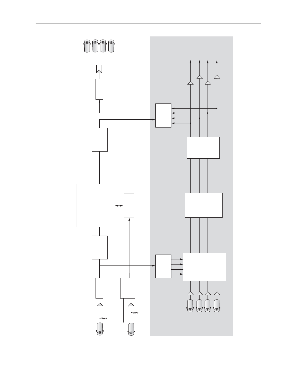
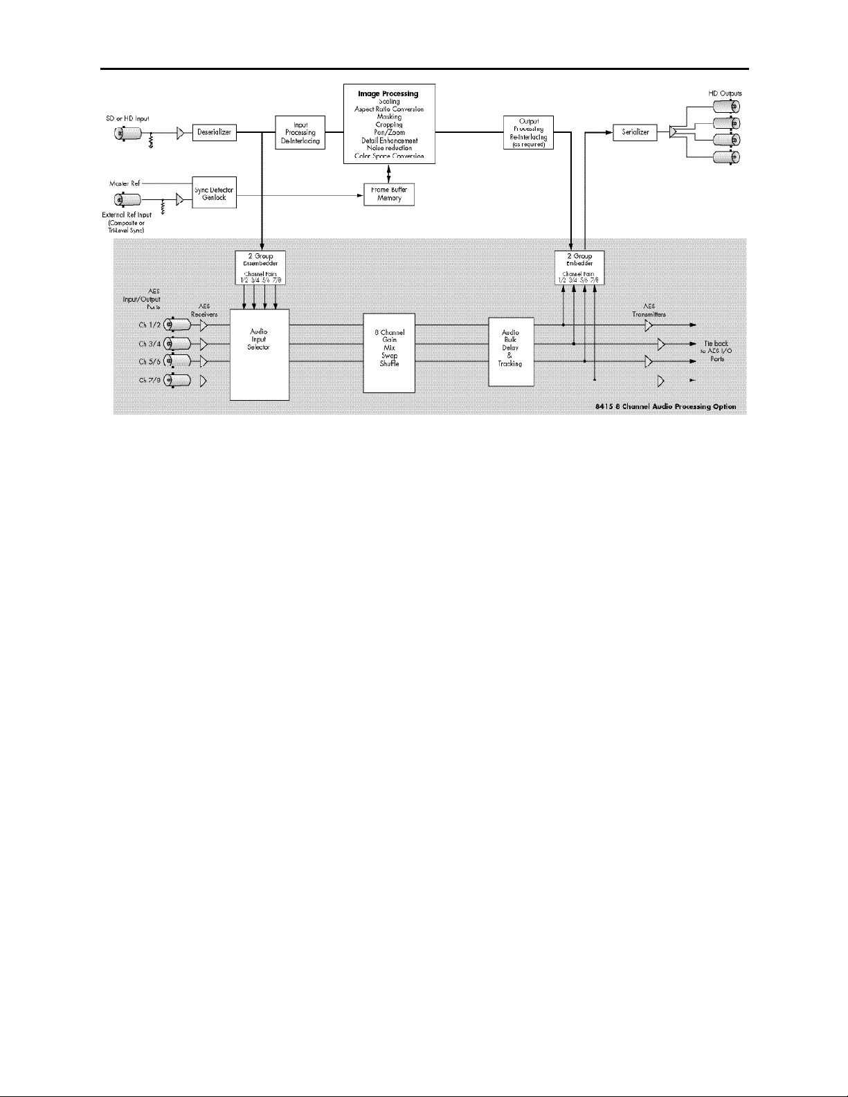
a signal ingest installation, or in a production application. Refer to the functional block
diagram for the module on the next page.
Sophisticated Adaptive Noise Reduction ensures delivery of a pristine output that is
excellent for use in broadcast. Picture Detail Enhancement is used to recover information
that has been lost due to poor frequency response upstream. Different aspect ratio conversion choices are available for selection on the HD output.
Input standard and frame rate are auto-detected. The 7910 automatically adjusts from SD
to HD color space and gamma. The built-in Proc Amp provides adjustment of signal
parameters with controls for Video Gain, Chroma, Pedestal, and Hue.
HD closed captioning is carried in data packets in the vertical interval ancillary data
space. The 7910 properly translates between traditional SD captioning (line 21 or 23) and
HD caption data so that closed captioning content is converted transparently between
video standards and formats.
The converted output is timeable with respect to the reference input. When converting to
film rate (1080sF/23.98) formats, 3:2 pulldown cadence is automatically detected and
backed out when present in the input. 3:2 detection can be enabled and disabled.
One of three types of audio submodules can be installed on the main circuit board:
• The 8415 is a 8 channel audio submodule with AES I/O that provides management
of embedded audio in the processing path, or supports audio embedding/disembedding
alongside the video processing elements. Embedded audio is safely bypassed
around the video frame store with lip sync preserved. Level adjustments and
channel shuffling are accessed through the built-in audio mixer. All audio
processing is performed at full 24 bit resolution by a digital signal processor (DSP).
• The 7610 audio submodule provides carriage of up to eight channels of embedded
audio through the format conversion process. Embedded audio in the input signal
is delayed to match the video delay and preserve lip sync. The delayed content is
reinserted in the video output. No level adjustment or channel swapping is
provided.
• The 7615 audio submodule also provides processing for signals with eight channels
of embedded audio. It offers the same processing and AES I/O as the 8415 plus the
ability to decode Dolby-E signals.
The 7910 can be configured locally or controlled and configured remotely with Avenue
Touch Screens, Express Panels, or Avenue PC Software. Alarm generators, configurable
user levels, module lock out, and customizable menus are just some of the tools included
in the Avenue Control system.
The on-board CPU can monitor and report module ID information (slot location, software
version and board revision), power status, and ancillary data status to the optional frame
System Control module. This information can be accessed by the user or set to register an
alarm if desired using the remote control options available.
7910-2
Page 3
Model 7910 HD Upconverter And Cross Converter
7910-3
Ch 5/6
Ch 7/8
Ch 1/2
Ch 3/4
SD or HD Input
HD Outputs
AES
Input/Output
Ports
AES
Receivers
AES
Transmitters
8415 8 Channel Audio Processing Option
Tie back
to AES I/O
Ports
Serializer
Input
Processing
De-Interlacing
2 Group
Disembedder
Output
Processing
Re-Interlacing
(as required)
Audio
Input
Selector
8 Channel
Gain
Mix
Swap
Shuffle
Audio
Bulk
Delay
&
Tracking
Image Processing
Scaling
Aspect Ratio Conversion
Masking
Cropping
Pan/Zoom
Detail Enhancement
Noise reduction
Color Space Conversion
Frame Buffer
Memory
Channel Pairs
1/2 3/4 5/6 7/8
2 Group
Embedder
Channel Pairs
1/2 3/4 5/6 7/8
Deserializer
External Ref Input
Master Ref
(Composite or
Tri-Level Sync)
Sync Detector
Genlock
7910 HD Upconverter And Cross Converter Functional Block Diagram, Landscape View
Page 4
Model 7910 HD Upconverter And Cross Converter
7910 HD Upconverter And Cross Converter Functional Block Diagram, Portrait View
7910-4
Page 5

Model 7910 HD Upconverter And Cross Converter
7910-5
(This page is intentionally blank.)
Page 6
Model 7910 HD Upconverter And Cross Converter
Power is derived from the ± 12 volt frame power. It is regulated to the required +5 volts
for the module by an on-board regulator. The module is fused with a resettable fuse
device. If the fuse opens due to an overcurrent condition, the module will lose power. After
pulling the module, the fuse will reset automatically requiring no replacement fuse.
Modules at software version 2.2.0 or later support SNMP (Simple Network Management
Protocol) monitoring. For each applicable signal processing module, module, signal, and
reference status are reported. For complete details on using SNMP monitoring, refer to
the Avenue System Overview in the manual that accompanies each frame.
APPLICATIONS
SD Upconversion
The 7910 module can be utilized to upconvert SD video from many different source types,
or cross convert HD video into all popular variations of 1080 and 720.
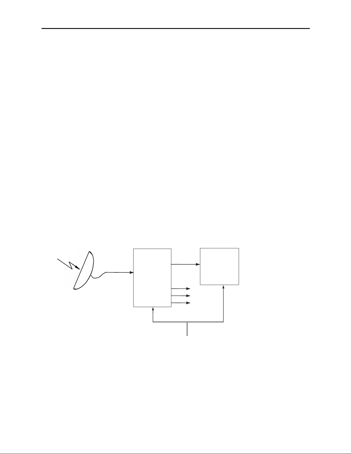
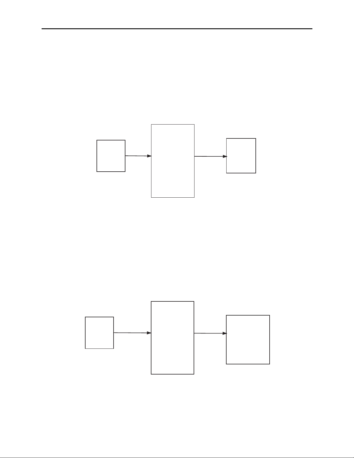
As shown in the example below, the SD ingest signal from a satellite is fed to a 7910
module where it is upconverted to feed an HD Master Control Switcher. The other three
outputs can be sent to other HD destinations.
Along with accurate upconversion, the module provides sophisticated adaptive noise
reduction for noisy input signals for use in broadcast applications. Timing to a house
reference is available on the module, along with many other controls features for ensuring
a clean, stable signal.
7910
Upconverter
HD Master
Control
Switcher
Other HD
Destinations
SD
Signal In
House Reference
7910 SD Upconverter Application
7910-6
Page 7
Model 7910 HD Upconverter And Cross Converter
APPLICATIONS
HD Cross Conversion
The 7910 module can be utilized to cross convert between HD 1.5 Gb/s formats, processing
all popular variations of 1080 and 720, making it simple for facilities to ingest any type of
HD signal. As shown in the example below, the 1080i input from an HD network feed is
fed to the 7910 where the format is converted to 720p as required for input to an HD router.
Auto Sensing Upconversion And Cross Conversion
The 7910 can either upconvert or cross convert as needed. As shown below, the output of
the 7910 has been set to 1080i. In this setup, the video server could, for example, play 720
or 1080 program material then play SD commercials. The 7910 will accept SD or HD
inputs and automatically convert to 1080i..
7910 HD Cross Converter Application
7910-7
Auto Sensing Upconversion And Cross Conversion Application
Network
Feed
1080i 720p
7910
Cross
Conversion
HD
Router
Video
Server
Any SD SDI
or HD SDI
signal
7910
1080i
HD
Master
Control
Switcher
Page 8
Model 7910 HD Upconverter And Cross Converter
INSTALLATION
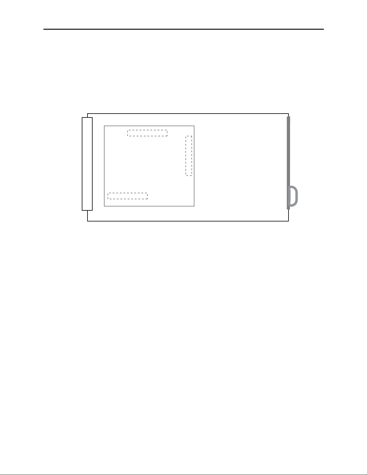
Audio Submodule Installation
The optional audio submodules install on the component side of the 7910 module circuit
board. If a submodule is ordered with the 7910, that module will come pre-installed.
To install an audio submodule manually, locate the three connectors on the left side of the
circuit board as shown below and line the connectors up, checking their alignment. Press
carefully into place to seat the submodule.
7910 Video Processing Module
Plug the 7910 module into any one of the slots in the 1 RU or 3 RU frame and install the
plastic overlay provided onto the corresponding group of rear BNC connectors associated
with the module location.
Note that the plastic overlay has an optional adhesive backing for securing it to the
frame. Use of the adhesive backing is only necessary if you would like the location to be
permanent and is not recommended if you need to change module locations. This module
may be hot-swapped (inserted or removed) without powering down or disturbing performance
of the other modules in the system.
CABLING
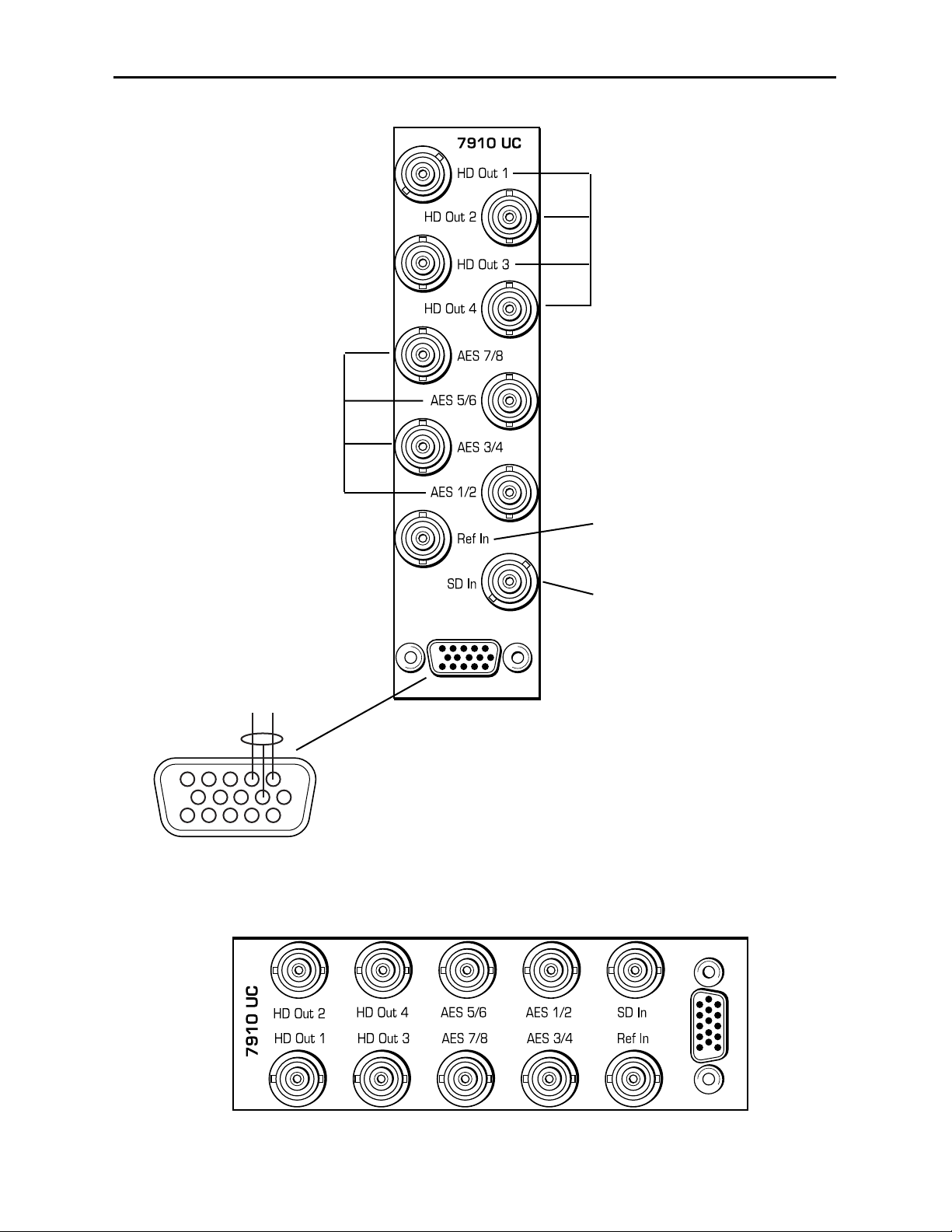
Refer to the 3 RU and 1 RU backplane diagrams of the module below for cabling
instructions. Unless stated otherwise, the 1 RU cabling explanations are identical to those
given in the 3 RU diagram.
7910-8
8415 Audio Processor
Audio Submodule Installation
Page 9
Model 7910 HD Upconverter And Cross Converter
Connect an SD or HD signal to
the SD In BNC to be upconverted
or cross converted.
Connect HD output destinations
to the converted signal at BNCs
HD Out 1 – HD Out 4.
3 RU Backplane
1 RU Backplane
7910-9
Connect AES audio input
signals to BNCs AES 1/2,
AES 3/4, AES 5/6, and
AES 7/8.
Connect an external
reference signal to the
Ref In BNC.
Connect LTC (Longitudinal Time
Code) input if required to the 15-pin
connector as shown below.
1
6
+-
11
LTC Input
Page 10

Model 7910 HD Upconverter And Cross Converter
MODULE CONFIGURATION AND CONTROL
The configuration parameters for each Avenue module must be selected after installation.
This can be done remotely using one of the Avenue remote control options, or locally using
the module front panel controls. Each module has a Remote/Local switch on the front
edge of the circuit board which must first be set to the desired control mode.
Configuration parameter choices for the module differ between Remote and Local modes.
In Remote mode, choices are made through software and allow more selections. The 7910
Parameter Table on page 9 summarizes and compares the various configuration
parameters that can be set remotely or locally and the default/factory settings. It also
shows the default User Levels for each control. These levels can be changed using the
Avenue PC application
If you are not using a remote control option, the module parameters must be configured
from the front panel switches. Parameters that have no front panel control will be set to a
default value. The Local switches are illustrated in the Front Panel Controls and
Indicators section on page 11. The Local switches are inactive when the Remote/Local
switch is in the Remote position.
In Remote mode, Avenue module parameters can be configured and controlled from one of
the remote control options, the Avenue Touch Screen, Avenue Express Control Panel, or
the Avenue PC Application. Once the module parameters have been set remotely, the
information is stored on the module’s CPU. This allows the module to be moved to a
different slot in the frame at your discretion without losing the stored information.
To set parameters remotely using the Avenue PC option, refer to the Avenue PC Remote
Configuration section on page 12.
To set parameters remotely using the Avenue Touch Screen option, refer to the Avenue
Touch Screen Remote Configuration section on page 23.
Express Panel operation is described in the data pack that accompanies the control panel
option.
7910-10
Page 11

Model 7910 HD Upconverter And Cross Converter
CONTROL LOCAL REMOTE
FACTORY
DEFAULT
DEFAULT
USER LEVEL
Reference Source Ext Ref
Ext Ref
Master Ref
Video In Ref
Ext Ref Level 1
Mode
Mode Switch1:
Ana or Proc
Mode Switch 2:
Box or Crop
Anamorphic
Pillar Box
Crop Sides
Manual
Anamorphic Level 1
Up Anamorphic
Anamorphic
Pillar Box
Crop
Manual
Anamorphic Level 1
HD Cross Anamorphic
Anamorphic
Manual
Anamorphic Level 1
Output Standard
Format Switch1:
1080i or 720p
If 1080i:
Format Switch2:
1080i or sF
720p/50
720p/59.94
1080i/50
1080i/59.94
1080i60
1080i/25
1080i/23.98
1080isF/25
1080isF/23.98
1080isF/24
1080i/59.94 Level 1
Width (Manual) 100% +/ – 100% 100% Admin
Height (Manual) 100% +/ – 100% 100% Admin
Hor Position
(Manual)
0% +/ – 100% 0% Admin
Ver Position
(Manual)
0% +/ – 100% 0% Admin
Noise Reduce Off
Off
Low
Medium
High
Off Admin
Detail Off
Off
Low
Medium
High
Off Admin
3:2 Detect Off
Off
On
Off Level 2
7910-11
Page 12

Model 7910 HD Upconverter And Cross Converter
7910-12
CONTROL LOCAL REMOTE
FACTORY
DEFAULT
DEFAULT
USER LEVEL
Gain 100% 0 – 150% 100% Admin
Chroma 100% 0 – 150% 100% Admin
Pedestal 0 IRE +/ – 30 IRE 0 IRE Admin
Hue 0 IRE +/ – 180 degrees 0 degrees Admin
Vert Blanking Wide Wide
Narrow
Wide Level 1
Test Pattern Off
Off
Bars
Black
Off Level 1
Hor Timing 0 clocks +/ – 2000 clocks 0 clocks Admin
Ver Timing 0 lines +/ – 1000 lines 0 lines Admin
Cpst Out Setup Off
Off
On
Off Level 2
Ch 1-8 In (level) 0 dB –70 to +12 dB 0 dB Level 1
Ch 1-8 Output Bus
Ch 1 – Output 1
Ch 2 – Output 2
Ch 3 – Output 3
Ch 4 – Output 4
Ch 5 – Output 5
Ch 6 – Output 6
Ch 7 – Output 7
Ch 8 – Output 8
Output Bus 1 – 8
Tie
Invert
Default
Ch 1 – Output 1
Ch 2 – Output 2
Ch 3 – Output 3
Ch 4 – Output 4
Ch 5 – Output 5
Ch 6 – Output 6
Ch 7 – Output 7
Ch 8 – Output 8
Level 1
Auto Track On
Off
On
On Level 1
Bulk Delay 0 msec 0 – 1000 msec 0 msec Level 1
1/2 Input
3/4 Input
5/6 Input
7/8 Input
Audio Switch 1:
AES or Embed
AES 1/2
AES 3/4
AES 5/6
AES 7/8
SDI 1/2
SDI 3/4
SDI 5/6
SDI 7/8
AES 1/2
AES 3/4
AES 5/6
AES 7/8
Level 1
7910 Parameter Table (Continued)
Page 13

Model 7910 HD Upconverter And Cross Converter
CONTROL LOCAL REMOTE
FACTORY
DEFAULT
DEFAULT
USER LEVEL
1/2, 3/4, 5/6, 7/8
Demux Group
Group 1 Group 1
Group 2
Group 3
Group 4
Group 1 Level 1
1/2, 3/4, 5/6, 7/8
Mode
Auto Audio
Data
Auto
Auto Level 1
Audio Embed
A and B
A Replace All
B Replace All
Off
Replace
Cascade
Replace All
A Replace All
B Replace All
Level 1
Mux Group
A and B
Group 1
Group 1
Group 2
Group 3
Group 4
Group 1 Level 1
Dig Ref Level –20 dBFS
–20 dBFS
–18 dBFS
–20 dBFS Level 1
CC Input Line Line 21 Lines 19 – 23 Line 21 Admin
Captions Out Off
Off
On
Off Level 1
Timecode Source LTC
LTC
VITC Line 14
VITC Line 15
VITC Line 16
VITC Line 17
VITC Line 18
VITC Line 19
VITC Line 20
LTC Level 1
Timecode Output Off
Off
LTC
VITC
LTC & VITC
Off Level 1
7910 Parameter Table (Continued)
7910-13
Page 14

Model 7910 HD Upconverter And Cross Converter
Front Panel Controls and Indicators
The front edge indicators and switch settings are shown in the diagram below:
7910-14
V
ideo In
green LED
:
ON indicates signal is present
and equalized.
OFF indicates no input or the
signal may not be present or
cable equalization exceeds
maximum length allowed.
Pwr green LED:
Indicates the presence (ON) or
absence (OFF) of power (+5V).
Run green LED
:
OFF:
A power fault of halted CPU
ON:
A halted CPU
FAST BLINK:
CPU Run error
SLOW BLINK:
System OK. (If SPI control is
active from the main frame
System Control Module, all
Run indicators will be
synchronized.).
AES 1/2, AES 3/4, AES 5/8,
AES 7/8 green LEDs:
ON when AES audio is detected
on the corresponding audio
input.
OFF when no AES audio is
detected on the corresponding
audio input.
Ref In green LED:
ON indicates external reference
signal is present and valid.
OFF indicates no external
reference is detected or is
invalid.
Embed
green LED:
On when an audio ancillary packet
is detected in the serial stream.
OFF when no audio ancillary
packet is detected.
Remote/Local switch:
Set to the mode you
will be using.
Format:
1080/720p switch:
Select the video upconversion format
to 1080 or 720p.
1080i/sF
switch: When a 1080 video
format is selected above, select
either 1080i or 1080sF.
Mode:
Ana/Proc switch:
Set the output mode to Ana
(Anamorphic) or Proc (Process).
Box/Crop
switch
:
When Proc is selected above, set
the output to either Box or Crop.
Audio:
AES/Embed switch:
Select AES or Embed to identify
what audio source is being input to
the module.
Page 15

Model 7910 HD Upconverter And Cross Converter
Avenue PC Remote Configuration
The Avenue PC remote control menus for this module are illustrated and explained below.
Refer to the 7910 Parameter Table for a summary of available parameters that can be
set remotely through the menus illustrated. The Configuration Summary gives tips and
general background information on setting the parameters. For more information on using
Avenue PC, refer to the Avenue PC Control Application Software data pack.
Parameter fields that are grayed out can indicate one of the following conditions:
• An option is not installed.
• The function is not active.
• The module is locked.
• The User Level set with Avenue PC is not accessible from the current User Level.
7910 AVENUE PC MENUS
The Vid In menu shown below allows you to configure the following:
• Ref Source – use this control to set the reference input source.
Status reporting is provided for the following conditions:
• Input – indicates signal is present and equalized.
• WSS/AFD In – the Wide Screen Signal/Active Format Descriptions In indicator
displays the format of the input signal connected to the Video In BNC as one of the
following: None, Full Frame, Letter 14:9, Letter 14:9T, Letter 16:9, Letter
16:9T, Anamorphic, Pillar 4x3, Pillar 14x9, Unknown WSS, Unknown AFD.
• Reference – reports the status of the reference input as either No Reference,
Ref 525 Lock, Ref 625 Lock, or Ref TLS Lock.
7910-15
Page 16

Model 7910 HD Upconverter And Cross Converter
The Mode menu shown below allows you to configure the following:
• Mode – use this control to set the aspect ratio for the upconverted HD video
output. When Manual is selected, use the Manual menu given next.
• Output Standard – use this control to set the desired output standard for
upconversion.
•Up– use this control to set the desired output aspect ratio when upconverting the
input signal (Anamorphic, Letter 16:9, Letter 14:9, Letter 13:9, Pillar, Crop
Sides 75%, Crop Sides 84%, Crop Top/Bot, WSS/AFD Auto 16x9, WSS/AFD
Auto 14x9, WSS/AFD Auto 4x3, Manual). When Manual is selected, use the
Manual menu to set the aspect ratio.
• HD Cross – use this control to set the desired output aspect ratio when cross
converting from one type of HD signal to another (Anamorphic, Letter 16:9,
Letter 14:9, Letter 13:9, Pillar, Crop Sides 75%, Crop Sides 84%, Crop
Top/Bot, WSS/AFD Auto 16x9, WSS/AFD Auto 14x9, WSS/AFD Auto 4x3,
Manual). When Manual is selected, use the Manual menu to set the aspect ratio.
7910-16
Page 17

Model 7910 HD Upconverter And Cross Converter
When Manual is selected in the Mode menu above, the Manual menu shown below will
become active. Set the aspect ratio of the upconverted HD output as desired with the
following controls:
• Width – set the aspect ratio width.
• Height – set the aspect ratio height.
• Hor Position – set the horizontal position of the output.
• Ver Position – set the vertical position of the output.
Use the Default button in each control to return to the default value.
Use the Config menu below to enable the following controls:
• Noise Reduce – adjusts the amount of noise reduction on the output signal from
Off, Low, Medium, or High. The typical setting for this parameter is Off or Low.
• Detail – adjusts the amount of picture detail enhancement on the output from
Low, Medium, or High. The typical setting for this parameter is Off or Low.
• 3:2 Detect – turns the control to detect video that has been converted from film,
On or Off. Use this only for film applications. The typical setting for this
parameter is Off.
7910-17
Page 18

Model 7910 HD Upconverter And Cross Converter
The Proc menu shown below allows you to adjust the following video processing parameters for
the signal:
• Gain – adjust the percentage of overall gain (luminance and chrominance).
• Chroma – adjust the percentage of chroma amplitude.
• Pedestal – adjust the pedestal (black) level of the signal in IRE.
• Hue – adjust the hue of the signal ± 180 degrees.
Use the Vid Out menu shown below to adjust the following parameters:
• Test Pattern – select a test pattern to be sent to the video output of the module.
• Hor Timing – adjust the horizontal timing of the output signal to place the
leading edge of sync coincident with other sources.
• Vertical Timing – set the vertical timing to a typical setting of 0 lines.
7910-18
Page 19
Model 7910 HD Upconverter And Cross Converter
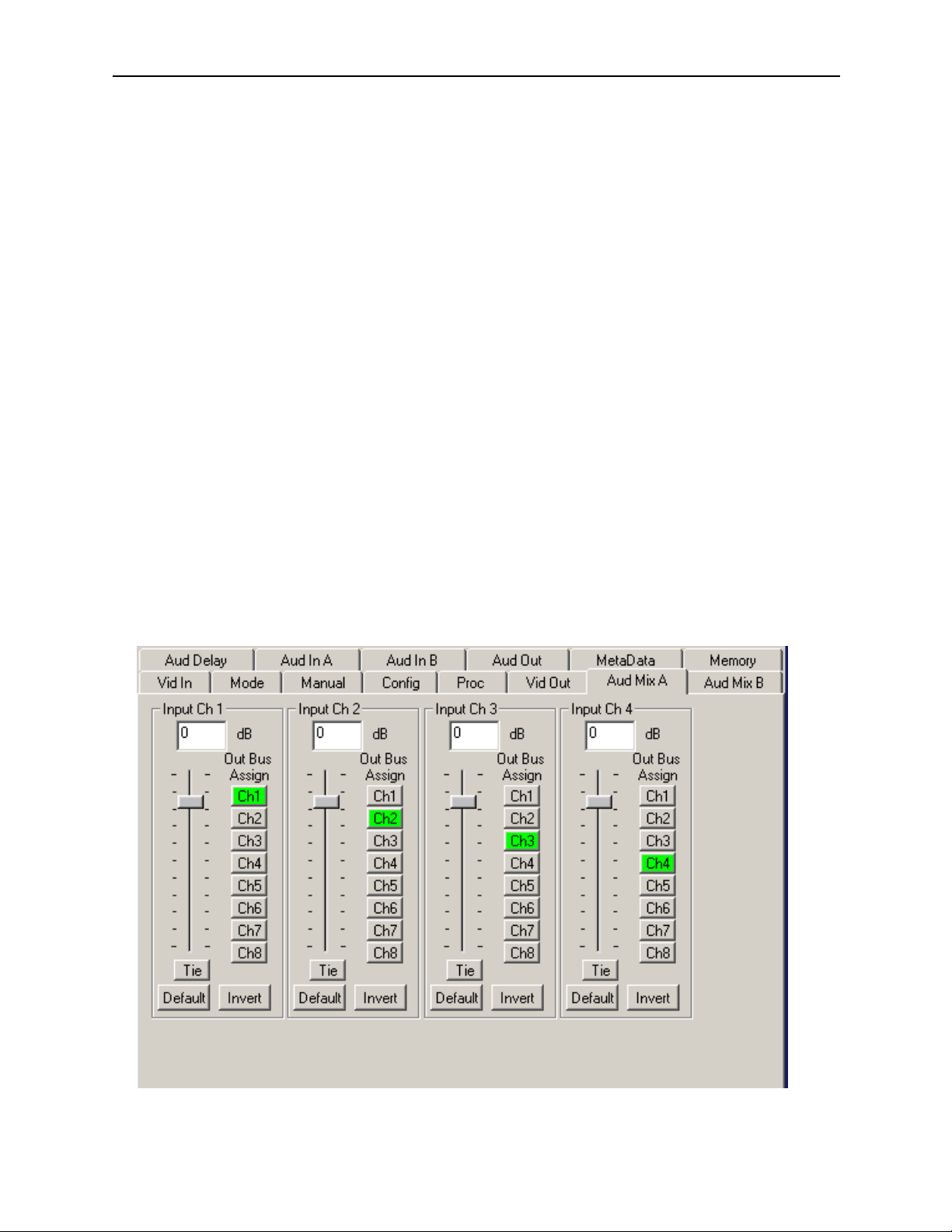
When an 8415 Audio Processor submodule is installed, use the Aud Mix A and B menus
control the audio mixing and shuffling of the module. Output bus assignments are
indicated in green.
For Channels 1 –4, use the Audio Mix A menu to set the following:
• Input Ch 1 – assign Input Channel 1 to the desired output bus or tie to
Channel 2. Set the input level using the slider control or by entering a number in
the window and pressing the Enter key on your PC.
• Input Ch 2 – assign Input Channel 2 to the desired output bus or tie to
Channel 1. Set the input level using the slider control or by entering a number in
the window and pressing the Enter key on your PC.
• Input Ch 3 – assign Input Channel 3 to the desired output bus or tie to
Channel 4. Set the input level using the slider control or by entering a number in
the window and pressing the Enter key on your PC.
• Input Ch 4 – assign Input Channel 4 to the desired output bus or tie to
Channel 3. Set the input level using the slider control or by entering a number in
the window and pressing the Enter key on your PC.
Selecting the Tie button in Input Ch 1 or Input Ch 2 will tie the two controls together.
Selecting the Tie button in Input Ch 3 or Input Ch 4 will tie the controls for these
channels together.
Select the Default button to return to the default value.
Select the Invert button to invert the phase of the audio content.
7910-19
Page 20
Model 7910 HD Upconverter And Cross Converter
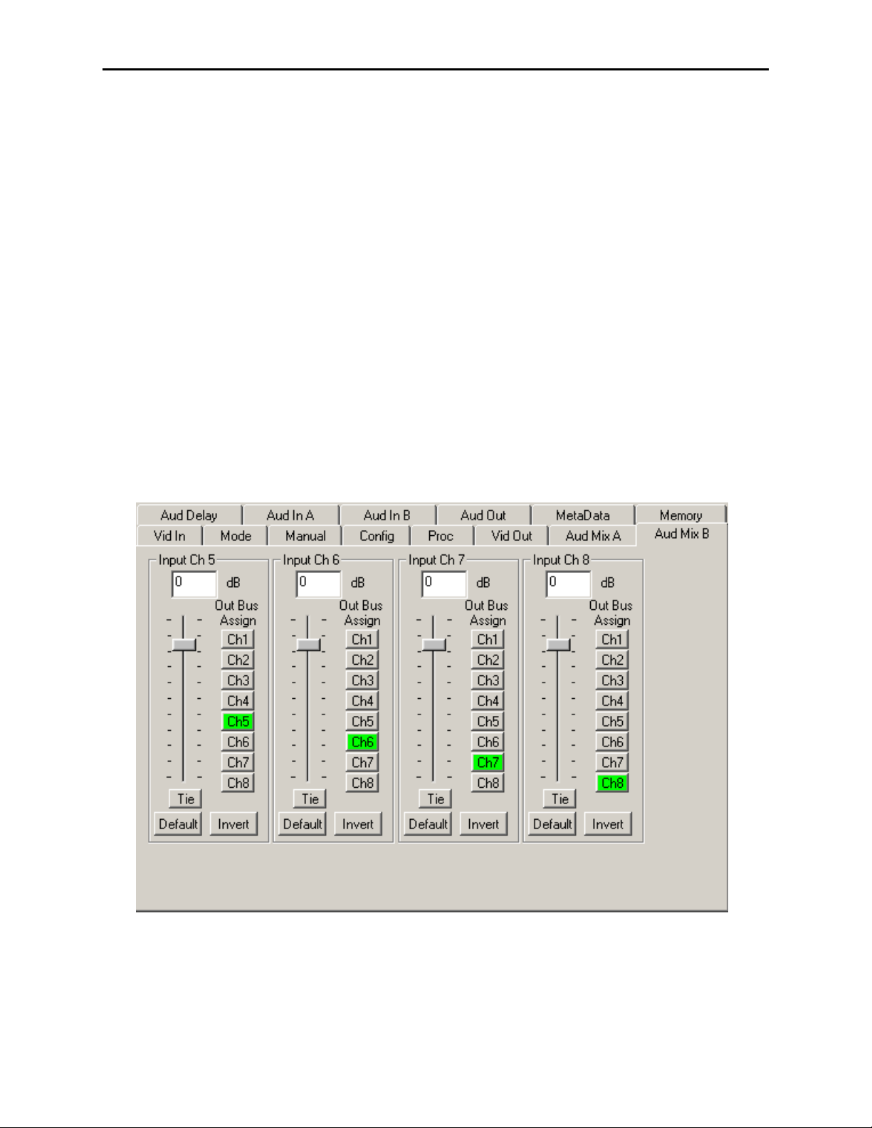
For Channels 5 – 8, use the Audio Mix B menu shown below to set the following:
• Input Ch 5 – assign Input Channel 5 to the desired output bus or tie to
Channel 6. Set the input level using the slider control or by entering a number in
the window and pressing the Enter key on your PC.
• Input Ch 6 – assign Input Channel 6 to the desired output bus or tie to
Channel 5. Set the input level using the slider control or by entering a number in
the window and pressing the Enter key on your PC.
• Input Ch 7 – assign Input Channel 7 to the desired output bus or tie to
Channel 8. Set the input level using the slider control or by entering a number in
the window and pressing the Enter key on your PC.
• Input Ch 8 – assign Input Channel 8 to the desired output bus or tie to
Channel 7. Set the input level using the slider control or by entering a number in
the window and pressing the Enter key on your PC.
Selecting the Tie button in Input Ch 5 or Input Ch 6 will tie the two controls together.
Selecting the Tie button in Input Ch 7 or Input Ch 8 will tie the controls for these
channels together.
Select the Default button to return to the default value.
Select the Invert button to invert the phase of the audio content.
7910-20
Page 21
Model 7910 HD Upconverter And Cross Converter
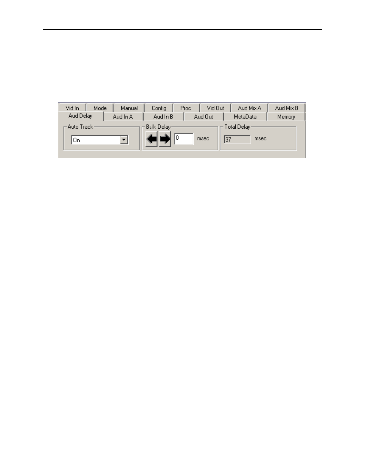
Use the Aud Delay menu shown below for the 8415 Audio submodule to adjust the
amount of audio delay on the output:
• Auto Track – enable auto tracking by selecting On or Off.
• Bulk Delay – set the amount of bulk delay using the left and right arrows or
enter a value in the msec field and press the Enter key on your PC.
The amount of total delay will be reported in msec in the Total Delay window.
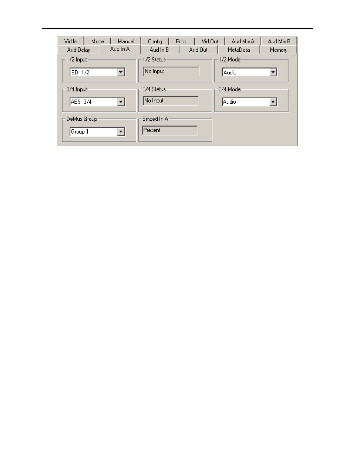
Use the Aud In A menu shown on the next page to adjust the following parameters:
• 1/2 Input – select the input audio source for Input 1/2.
• 3/4 Input – select the input audio source for Input 3/4.
When an AES input pair is selected as an input, the corresponding AES BNC on
the rear of the module will become an input. If an AES input is not selected, the
corresponding BNC on the rear of the module will automatically become an output.
Refer to the block diagram on page 4 for an illustration of the input/output BNCs.
• 1/2 Mode – for a Serial input with embedded audio, select the type of audio in the
stream:
• Audio – the embedded stream is standard audio.
• Data – the embedded stream is a non-audio signal.
• Auto – the module will detect the type of signal embedded in the stream,
audio or data.
• 3/4 Mode – select the type of audio in the serial stream as described above.
• Demux Group – select the embedded audio group to demultiplex from the
selections. The status of embedded audio is shown in the Embed In view.
The status of the corresponding audio inputs are shown next to the control. Status is
reported as one of the following:
• No Input – no serial digital embedded audio is detected.
• Audio Sync – the audio embedded in the stream is synchronous with the timing
reference.
• Data Sync – the data embedded in the stream is synchronous with the timing
reference.
• Audio Async – the audio embedded in the stream is non-synchronous with the
timing reference.
7910-21
Page 22
Model 7910 HD Upconverter And Cross Converter
Use the Aud In B menu shown on the next page to adjust the following parameters:
• 5/6 Input – select the input audio source for Input 5/6.
• 7/8 Input – select the input audio source for Input 7/8.
When an AES input pair is selected as an input, the corresponding AES BNC on
the rear of the module will become an input. If an AES input is not selected, the
corresponding BNC on the rear of the module will automatically become an output.
Refer to the block diagram on page 4 for an illustration of the input/output BNCs.
• 5/6 Mode – for a Serial input with embedded audio, select the type of audio in the
stream:
• Audio – the embedded stream is standard audio.
• Data – the embedded stream is a non-audio signal.
• Auto – the module will detect the type of signal embedded in the stream,
audio or data.
• 7/8 Mode – select the type of audio in the serial stream as described above.
• Demux Group – select the embedded audio group to demultiplex from the selections. The status of embedded audio is shown in the Embed In view.
The status of the corresponding audio inputs are shown next to the control. Status is
reported as one of the following:
• No Input – no serial digital embedded audio is detected.
• Audio Sync – the audio embedded in the stream is synchronous with the timing
reference.
• Data Sync – the data embedded in the stream is synchronous with the timing
reference.
• Audio Async – the audio embedded in the stream is non-synchronous with the
timing reference.
7910-22
Page 23

Model 7910 HD Upconverter And Cross Converter
Use the Aud Out menu shown below to adjust the following audio output parameters:
• Audio Embed A – turn embedding Off for no embedding to take place in the
output signal. Select Replace to replace the targeted group in the stream with
new content. If there is no such group already present, the new content will be
placed in the horizontal interval in normal cascade, following any other content
already there. When Cascade is selected, the audio channels are placed after any
existing content. Replace All will strip all of the original content and the new
content is placed at the beginning of the horizontal interval.
• Audio Embed B – identical to Audio Embed A but no Replace All function is
required as this will occur upstream in the A embedder.
• Mux Group A – select the multiplexed group to be embedded in embedder A in
the output.
• Mux Group B – select the multiplexed group to be embedded in embedder B in
the output.
• Dig Ref Level – set the digital reference level for the audio output.
7910-23
Page 24
Model 7910 HD Upconverter And Cross Converter
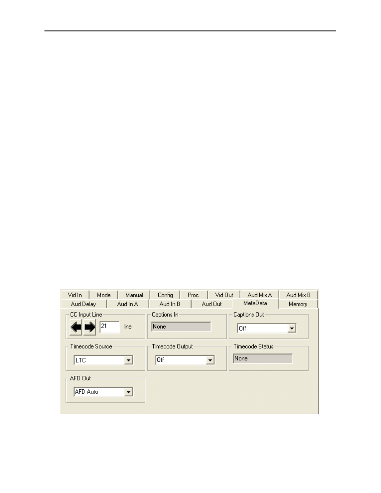
The MetaData menu reports or provides settings for the following closed captioning and
timecode parameters:
• CC Input Line – You do not need to set the value for this control. If an SD signal
is present on the input, the module will autosense which line the caption data is
on and report that information in the Captions In box.
• Captions In – Reports the status of caption data on the input signal as None,
Line 21, Line 23, CEA608 or CEA708.
• Captions Out – If the Captions In display reports the presence of closed caption-
ing, set to On for passing the captions through to the output or turn Off closed
captioning on the output.
• Timecode Source – set the type of timecode source present in the input signal,
LTC, VITC Line 14 through VITC Line 20.
• Timecode Output – set the type of timecode for insertion on the output signal.
• Timecode Status display will report None, Line 21, Line 23, CEA608 or
CEA708.
• AFD Out – set the AFD (Active Format Description) output code for the desired
aspect ratio. AFD is a four-bit code that defines the active image area and
protected image areas for various combinations of aspect ratios. Available values
for this field are:
7910-24
AFD Auto (default value)
The following additional values represent binary codes:
AFD 0001
AFD 0010
AFD 0011
AFD 0100
AFD 0101
AFD 0110
AFD 0111
AFD 1000
AFD 1001
AFD 1010
AFD 1011
AFD 1100
AFD 1101
AFD 1110
AFD 1111
Page 25
Model 7910 HD Upconverter And Cross Converter
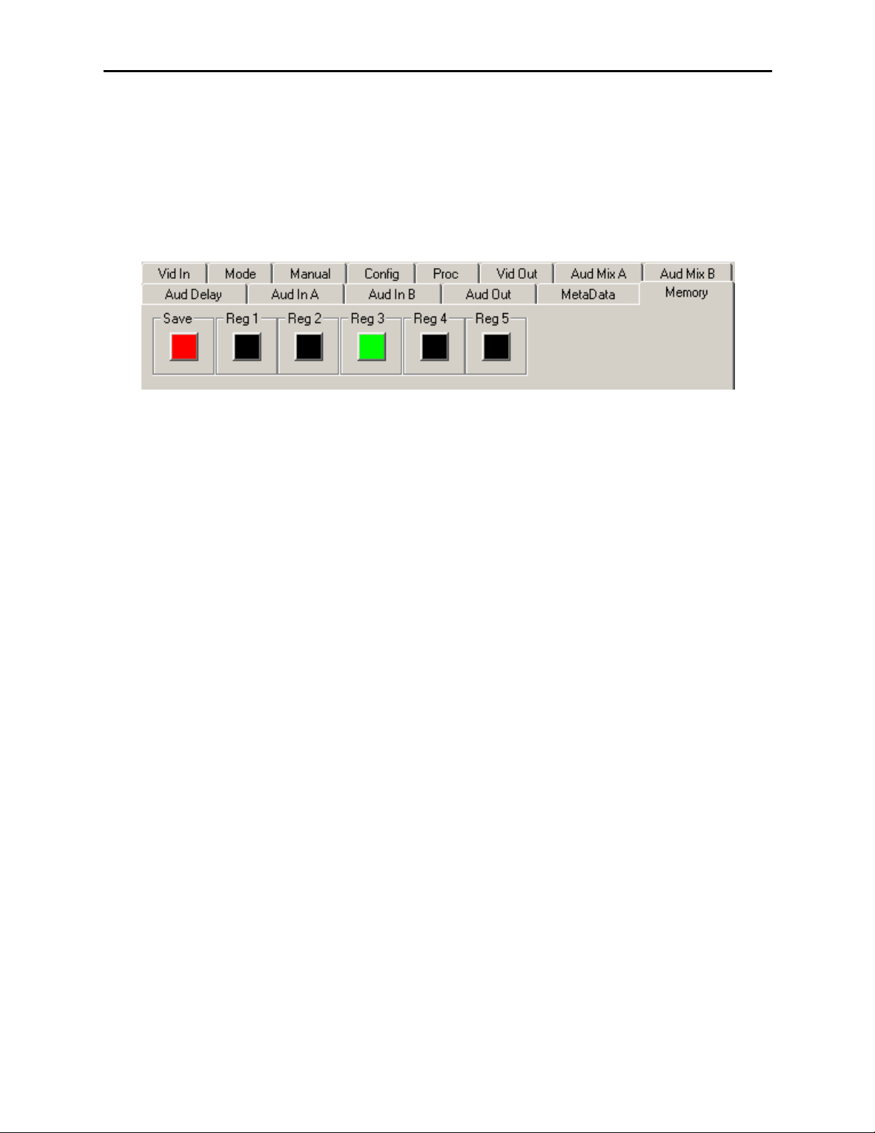
The Memory menu shown below allows you to save overall module setups to five memory
registers as follows:
• Select Save, then one of the five memory registers Reg 1 – 5. The box will turn
green. The entire module setup is now saved in the selected register.
• To recall a register, select the register box. If there is information saved, the box
will turn green. The saved setup will now be loaded to the module. Up to five
different module setups can be saved and recalled using the individual registers.
7910-25
Page 26

Model 7910 HD Upconverter And Cross Converter
Avenue Touch Screen Remote Configuration
The Avenue Touch Screen remote control menus for this module are illustrated and
explained below. Refer to the 7910 Parameter Table for a summary of available
parameters that can be set remotely through the menus illustrated. The Configuration
Summary gives tips and general background information on setting the parameters. For
more information on using Avenue PC, refer to the Avenue PC Control Application
Software data pack.
Parameter fields that are grayed out can indicate one of the following conditions:
• An option is not installed.
• The function is not active.
• The module is locked.
• The User Level set with Avenue PC is not accessible from the current User Level.
7910 Avenue Touch Screen Menus
The Vid In menu shown below allows you to configure the following:
• Ref Source – use this control to set the reference input source.
Status reporting is provided for the following conditions:
• Input – indicates signal is present and equalized.
• WSS/AFD In – the Wide Screen Signal/Active Format Descriptions In indicator
displays the format of the input signal connected to the Video In BNC as one of the
following: None, Full Frame, Letter 14:9, Letter 14:9T, Letter 16:9, Letter
16:9T, Anamorphic, Pillar 4x3, Pillar 14x9, Unknown WSS, Unknown AFD.
• Reference – reports the status of the reference input as either No Reference,
Ref 525 Lock, Ref 625 Lock, or Ref TLS Lock.
7910-26
Page 27

Model 7910 HD Upconverter And Cross Converter
The Mode menu shown below allows you to configure the following:
• Mode – use this control to set the aspect ratio for the upconverted HD video
output. When Manual is selected, use the Manual menu given next.
• Output Standard – use this control to set the desired output standard for
upconversion.
•Up– use this control to set the desired output aspect ratio when upconverting the
input signal (Anamorphic, Letter 16:9, Letter 14:9, Letter 13:9, Pillar, Crop
Sides 75%, Crop Sides 84%, Crop Top/Bot, WSS/AFD Auto 16x9, WSS/AFD
Auto 14x9, WSS/AFD Auto 4x3, Manual). When Manual is selected, use the
Manual menu to set the aspect ratio.
• HD Cross – use this control to set the desired output aspect ratio when cross converting from one type of HD signal to another (Anamorphic, Letter 16:9, Letter
14:9, Letter 13:9, Pillar, Crop Sides 75%, Crop Sides 84%, Crop Top/Bot,
WSS/AFD Auto 16x9, WSS/AFD Auto 14x9, WSS/AFD Auto 4x3, Manual).
When Manual is selected, use the Manual menu to set the aspect ratio.
7910-27
Page 28
Model 7910 HD Upconverter And Cross Converter
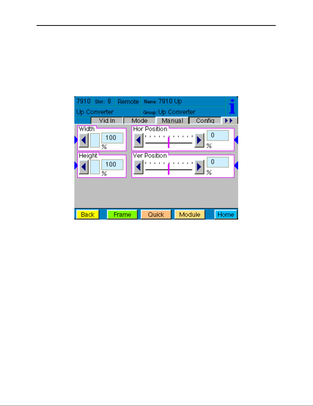
When Manual is selected in the Mode menu above, you may set the output format mode
of the upconverted HD output with the following controls:
• Width – set the width of the output .
• Height – set the height of the output .
• Hor Position – set the horizontal position of the output.
• Ver Position – set the vertical position of the output.
Use the Default button in each control to return to the default value.
7910-28
Page 29

Model 7910 HD Upconverter And Cross Converter
Use the Config menu below to enable the following controls:
• Noise Reduce – adjusts the amount of noise reduction on the output signal from
Off, Low, Medium, or High. The typical setting for this parameter is Off or Low.
• Detail – adjusts the amount of picture detail enhancement on the output from
Low, Medium, or High. The typical setting for this parameter is Off or Low.
• 3:2 Detect – turns the control to detect video that has been converted from film,
On or Off. Use this only for film applications. The typical setting for this
parameter is Off.
7910-29
Page 30

Model 7910 HD Upconverter And Cross Converter
The Proc menu shown below allows you to adjust the following video processing parameters for the signal:
• Gain – adjust the percentage of overall gain (luminance and chrominance).
• Chroma – adjust the percentage of chroma amplitude.
• Pedestal – adjust the pedestal (black) level of the signal in IRE.
• Hue – adjust the hue of the signal ± 180 degrees.
7910-30
Page 31

Model 7910 HD Upconverter And Cross Converter
Use the Vid Out menu shown below to adjust the following parameters:
• Test Pattern – select a test pattern to be sent to the video output of the module.
• Hor Timing – adjust the horizontal timing of the output signal to place the
leading edge of sync coincident with other sources.
• Vertical Timing – set the vertical timing to a typical setting of 0 lines.
7910-31
Page 32

Model 7910 HD Upconverter And Cross Converter
When an 8415 Audio Processor submodule is installed, use the Aud Mix A and B menus
shown next to control the audio mixing and shuffling of the module. Output bus assignments are indicated in green.
For Channels 1 –4, use the Audio Mix A menu to set the following:
• Input Ch 1 – assign Input Channel 1 to the desired output bus or tie to
Channel 2. Set the input level using the slider control or by entering a number in
the pop-up keypad and pressing the Enter key.
• Input Ch 2 – assign Input Channel 2 to the desired output bus or tie to
Channel 1. Set the input level using the slider control or by entering a number in
the pop-up keypad and pressing the Enter key.
• Input Ch 3 – assign Input Channel 3 to the desired output bus or tie to
Channel 4. Set the input level using the slider control or by entering a number in
the pop-up keypad and pressing the Enter key.
• Input Ch 4 – assign Input Channel 4 to the desired output bus or tie to
Channel 3. Set the input level using the slider control or by entering a number in
the pop-up keypad and pressing the Enter key.
Selecting the Tie button in Input Ch 1 or Input Ch 2 will tie the two controls together.
Selecting the Tie button in Input Ch 3 or Input Ch 4 will tie the controls for these
channels together.
Select the Default button to return to the default value.
Select the Invert button to invert the phase of the audio content.
7910-32
Page 33
Model 7910 HD Upconverter And Cross Converter
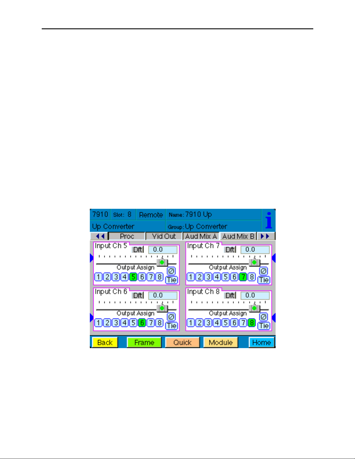
For Channels 5 – 8, use the Audio Mix B menu shown below to set the following:
• Input Ch 5 – assign Input Channel 5 to the desired output bus or tie to
Channel 6. Set the input level using the slider control or by entering a number in
the pop-up keypad and pressing the Enter key.
• Input Ch 6 – assign Input Channel 6 to the desired output bus or tie to
Channel 5. Set the input level using the slider control or by entering a number in
the pop-up keypad and pressing the Enter key.
• Input Ch 7 – assign Input Channel 7 to the desired output bus or tie to
Channel 8. Set the input level using the slider control or by entering a number in
the pop-up keypad and pressing the Enter key.
• Input Ch 8 – assign Input Channel 8 to the desired output bus or tie to
Channel 7. Set the input level using the slider control or by entering a number in
the pop-up keypad and pressing the Enter key.
Selecting the Tie button in Input Ch 5 or Input Ch 6 will tie the two controls together.
Selecting the Tie button in Input Ch 7 or Input Ch 8 will tie the controls for these
channels together.
Select the Default button to return to the default value.
Select the Invert button to invert the phase of the audio content.
7910-33
Page 34

Model 7910 HD Upconverter And Cross Converter
Use the Aud Delay menu shown below for the 8415 Audio submodule to adjust the
amount of audio delay on the output:
• Auto Track – enable auto tracking by selecting On or Off.
• Bulk Delay – set the amount of bulk delay using the left and right arrows or enter
a value in the msec field with the pop-up keypad and press the Enter key.
The amount of total delay will be reported in msec in the Total Delay window.
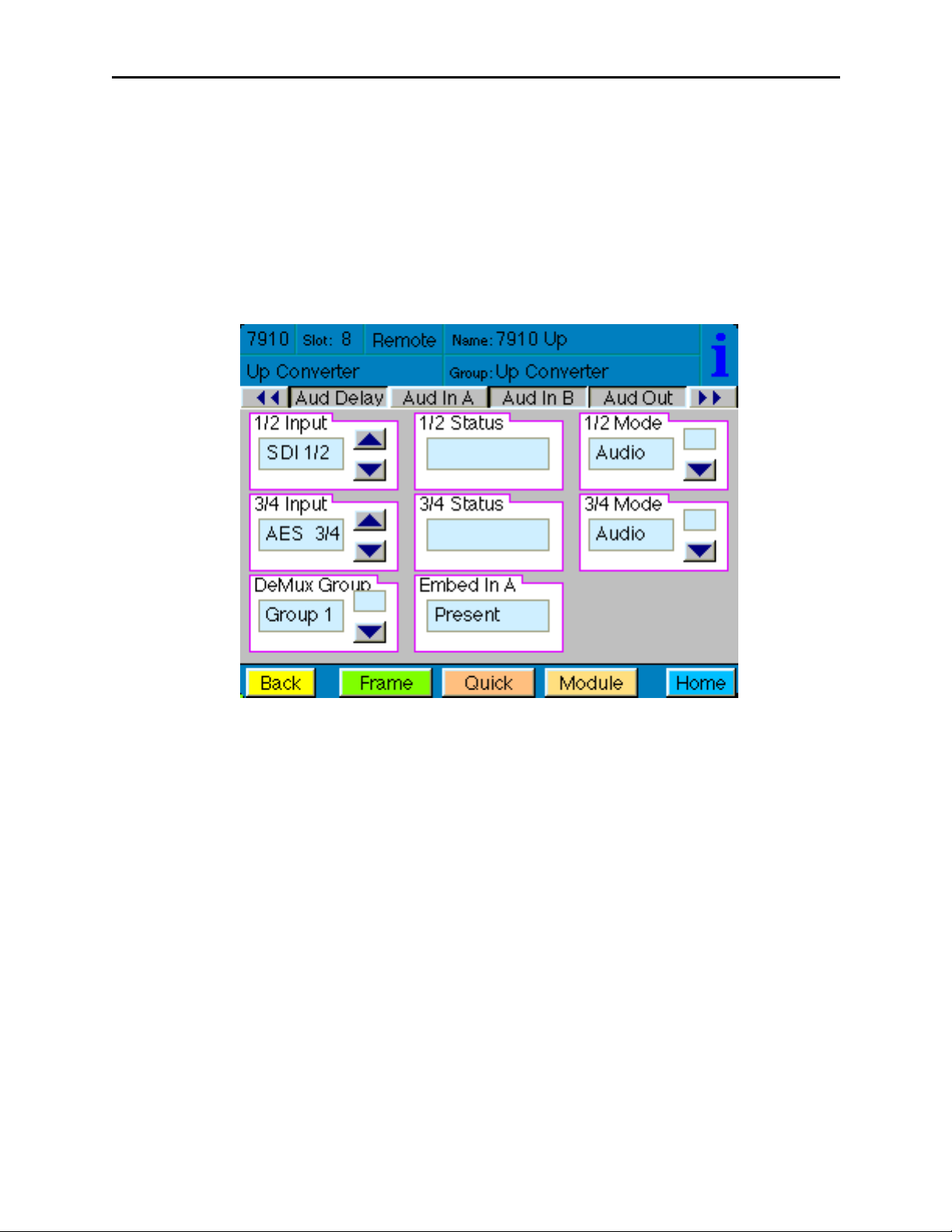
Use the Aud In A menu shown on the next page to adjust the following parameters:
• 1/2 Input – select the input audio source for Input 1/2.
• 3/4 Input – select the input audio source for Input 3/4.
When an AES input pair is selected as an input, the corresponding AES BNC on
the rear of the module will become an input. If an AES input is not selected, the
corresponding BNC on the rear of the module will automatically become an output.
Refer to the block diagram on page 4 for an illustration of the input/output BNCs.
• 1/2 Mode – for a Serial input with embedded audio, select the type of audio in the
stream:
• Audio – the embedded stream is standard audio.
• Data – the embedded stream is a non-audio signal.
• Auto – the module will detect the type of signal embedded in the stream,
audio or data.
• 3/4 Mode – select the type of audio in the serial stream as described above.
• DeMux Group – select the embedded audio group to demultiplex from the selections. The status of embedded audio is shown in the Embed In view.
7910-34
Page 35
Model 7910 HD Upconverter And Cross Converter
The status of the corresponding audio inputs are shown next to the control. Status is
reported as one of the following:
• No Input – no serial digital embedded audio is detected.
• Audio Sync – the audio embedded in the stream is synchronous with the timing
reference.
• Data Sync – the data embedded in the stream is synchronous with the timing
reference.
• Audio Async – the audio embedded in the stream is non-synchronous with the
timing reference.
Use the Aud In B menu shown on the next page to adjust the following parameters:
• 5/6 Input – select the input audio source for Input 5/6.
• 7/8 Input – select the input audio source for Input 7/8.
When an AES input pair is selected as an input, the corresponding AES BNC on
the rear of the module will become an input. If an AES input is not selected, the
corresponding BNC on the rear of the module will automatically become an output.
Refer to the block diagram on page 4 for an illustration of the input/output BNCs.
• 5/6 Mode – for a Serial input with embedded audio, select the type of audio in the
stream:
• Audio – the embedded stream is standard audio.
• Data – the embedded stream is a non-audio signal.
• Auto – the module will detect the type of signal embedded in the stream,
audio or data.
• 7/8 Mode – select the type of audio in the serial stream as described above.
• DeMux Group – select the embedded audio group to demultiplex from the
selections. The status of embedded audio is shown in the Embed In view.
7910-35
Page 36

Model 7910 HD Upconverter And Cross Converter
The status of the corresponding audio inputs are shown next to the control. Status is
reported as one of the following:
• No Input – no serial digital embedded audio is detected.
• Audio Sync – the audio embedded in the stream is synchronous with the timing
reference.
• Data Sync – the data embedded in the stream is synchronous with the timing
reference.
• Audio Async – the audio embedded in the stream is non-synchronous with the
timing reference.
7910-36
Page 37
Model 7910 HD Upconverter And Cross Converter
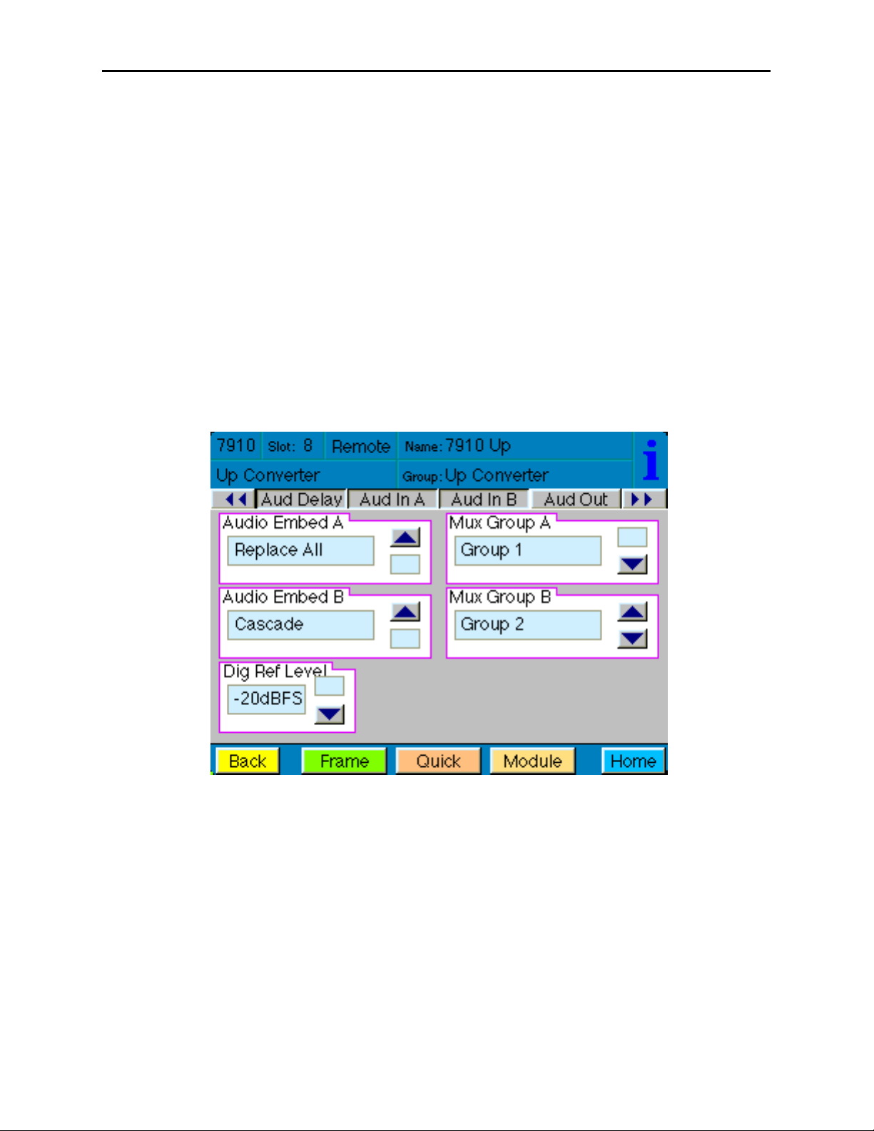
Use the Aud Out menu shown below to adjust the following audio output parameters:
• Audio Embed A – turn embedding Off for no embedding to take place in the
output signal. Select Replace to replace the targeted group in the stream with
new content. If there is no such group already present, the new content will be
placed in the horizontal interval in normal cascade, following any other content
already there. When Cascade is selected, the audio channels are placed after any
existing content. Replace All will strip all of the original content and the new
content is placed at the beginning of the horizontal interval.
• Audio Embed B – identical to Audio Embed A but no Replace All function is
required as this will occur upstream in the A embedder.
• Mux Group A – select the multiplexed group to be embedded in embedder A in
the output.
• Mux Group B – select the multiplexed group to be embedded in embedder B in
the output.
• Dig Ref Level – set the digital reference level for the audio output.
7910-37
Page 38

Model 7910 HD Upconverter And Cross Converter
The MetaData menu reports or provides settings for the following closed captioning and
timecode parameters:
• CC Input Line – You do not need to set the value for this control. If an SD signal
is present on the input, the module will autosense which line the caption data is
on and report that information in the Captions In box.
• Captions In – Reports the status of caption data on the input signal as None,
Line 21, Line 23, CEA608 or CEA708.
• Captions Out – If the Captions In display reports the presence of closed caption-
ing, set to On for passing the captions through to the output or turn Off closed
captioning on the output.
• Timecode Source – set the type of timecode source present in the input signal,
LTC, VITC Line 14 through VITC Line 20.
• Timecode Output – set the type of timecode for insertion on the output signal.
• Timecode Status display will report None, Line 21, Line 23, CEA608 or
CEA708.
• AFD Out – set the AFD (Active Format Description) output code for the desired
aspect ratio. AFD is a four-bit code that defines the active image area and
protected image areas for various combinations of aspect ratios. Available values
for this field are:
7910-38
AFD Auto (default value)
The following additional values represent binary codes:
AFD 0001
AFD 0010
AFD 0011
AFD 0100
AFD 0101
AFD 0110
AFD 0111
AFD 1000
AFD 1001
AFD 1010
AFD 1011
AFD 1100
AFD 1101
AFD 1110
AFD 1111
Page 39

Model 7910 HD Upconverter And Cross Converter
The Memory menu shown below allows you to save overall module setups to five memory
registers as follows:
• Select Save, then one of the five memory registers Reg 1 – 5. The box will turn
green. The entire module setup is now saved in the selected register.
• To recall a register, select the register box. If there is information saved, the box
will turn green. The saved setup will now be loaded to the module. Up to five
different module setups can be saved and recalled using the individual registers.
7910-39
Page 40

Model 7910 HD Upconverter And Cross Converter
7910-40
TROUBLESHOOTING
As a troubleshooting aid, the signal presence, power and CPU status can be easily
monitored from the front panel of this module using the indicators explained in the Front
Panel Switches and Indicators section.
The following status items can be monitored using the Avenue Touch Screen Control
Panel, Express Panel, or PC Application:
• Input Status
• Slot ID, Software Version and Board Revision
Refer to the overall troubleshooting tips given below for the module:
No status lights are lit on front panel:
• Check that frame power is present (green LED{s} on frame power supplies).
• Check that module is firmly seated in frame. Try removing it and plugging
it in again.
Can’t control module:
• Check status of CPU Run green LED. Should be blinking slowly and in
unison with other modules if System module is present. If not, try removing
it and plugging it in again.
• System module may not be working properly if installed.
No video or audio signal out of module:
• Check status of In green LEDs. If not lit, check the input signal for
presence and quality.
• Check cabling to input of module.
You may also refer to the technical support section of the Ensemble web site for the latest
information on your equipment at the URL below:
http://www
.ensembledesigns.com/support
SOFTWARE UPDATING
Software upgrades for each module can be downloaded remotely if the optional System
Control module is installed. These can be downloaded onto your PC and Avenue PC will
distribute the update to the individual module. (Refer to the Avenue PC documentation for
more information.) Periodically updates will be posted on our web site. If you do not have
the required System Control Module and Avenue PC, modules can be sent back to the
factory for software upgrades.
Page 41

Model 7910 HD Upconverter And Cross Converter
WARRANTY AND FACTORY SERVICE
Warranty
This Module is covered by a five year limited warranty, as stated in the main Preface of
this manual. If you require service (under warranty or not), please contact Ensemble
Designs and ask for customer service before you return the unit. This will allow the
service technician to provide any other suggestions for identifying the problem and
recommend possible solutions.
Factory Service
If you return equipment for repair, please get a Return Material Authorization Number
(RMA) from the factory first.
Ship the product and a written description of the problem to:
Ensemble Designs, Inc.
Attention: Customer Service RMA #####
870 Gold Flat Rd.
Nevada City, CA. 95959 USA
(530) 478-1830
Fax: (530) 478-1832
service@ensembledesigns.com
http://www.ensembledesigns.com
Be sure to put your RMA number on the outside of the box.
7910-41
Page 42

Model 7910 HD Upconverter And Cross Converter
SPECIFICATIONS
7910 HD Upconverter
Serial Digital Input:
Number: One
Signal Type: SD Serial Digital 270 Mb/s
SMPTE 259M
(both 525 and 625 SD standards)
HD Serial Digital 1.485 Gb/s
SMPTE 274M, 292M, or 296M
Impedance: 75 Ω, BNC
Return Loss: >15 dB
Maximum Cable
Length:
270 Mb/s 300 meters (Belden 1694A or equivalent)
1.485 Gb/s 100 meters (Belden 1694A or equivalent)
Serial Digital Output
Number: Four
Type: HD Serial Digital 1.485 Gb/s
SMPTE 274M or 296M
Impedance: 75 Ω, BNC
Return Loss: >15 dB
Output DC: None (AC coupled)
HD Standards Supported
1080i (SMPTE 274M -4,5,6) 50, 59.94, 60 Hz
720p (SMPTE 296M -1,2,3) 50, 59.94, 60Hz
1080p (SMPTE 274M -9,10,11) 23.98, 24, 25 Hz
1080sF (RP211 -14,15,16) 23.98, 24, 25 Hz
Reference Input
Number: One external (module’s BNC)
One internal (frame master ref BNC)
Signal Type: PAL or NTSC composite video
or HD Tri-Level Sync
SMPTE 274M or 296M
Return Loss: >40 dB (applies to external ref input)
Conversion Directions
Upconversion between:
525 (NTSC) and 1080i/59.94, 720p/59.94, 1080p/23.98, 1080sF/23.98
625 (PAL) and 1080i/50, 720p/50, 1080p/25, 1080sF/25
Cross Conversion within frame rate families:
525 Derived Family: 1080i/59.94, 720p/59.94, 1080p/23.98, and 1080sF/23.98
625 Derived Family: 1080i/50, 720p/50, 1080p/25, 1080sF/25
7910-42
Page 43

Model 7910 HD Upconverter And Cross Converter
AES/EBU Digital Inputs
Number: Four (total of eight channels)
Type: AES3id
Connectorization: Coaxial, 75 Ω BNC
Bit Depth: 20 or 24 Bit
Sample Rate: 30 kHz to 100 kHz
(sample rate converted internally to 48 kHz)
Crosstalk: < 144 dB
Dynamic Range: > 144 dB
Reference Level: -18 or -20 dBFS (Selectable)
AC-3, Dolby-E: Supported when inputs are synchronous
Embedded Inputs
Number: Four AES streams (from video input)
Eight channels from any two of four groups
Selectable to any of four groups
Type: SMPTE 274M Compliant
Selectable to any of four groups
Channels: Eight
Bit Depth: 20 or 24 Bit
AES/EBU Digital Outputs
Number: Four (total of eight channels)
Type: AES3id
Connectorization: Coaxial, 75 Ω BNC
Bit Depth: 20 or 24 Bit
Sample Rate: 48 kHz
Synchronous to Video output
Reference Level: -18 or -20 dBFS (Selectable)
Embedded Output
Number: Four or two, depending on configuration
Group Assign: Cascade, or Replace any of two of four groups
Channels: Eight
Bit Depth: 24 Bit
General Specifications
Power Consumption: < 10 Watts
Temperature Range: 0 to 40 degrees C ambient (all specs met)
Relative Humidity: 0 to 95% noncondensing
Altitude: 0 to 10,000 ft
Due to ongoing product development, all specifications subject to change.
7910-43
 Loading...