


7110
Table of contents
 Loading...
Model 7110 HD/SD/ASI and
Model 9110 3G/HD/SD/ASI
Reclocking DA
User Guide
Revision 2.1 SW v2.2.0
By Engineers, For Engineers
In 1989, a former television station engineer who loved
designing and building video equipment, decided to
start a new company. He relished the idea of taking
an existing group of equipment and adding a few
special pieces in order to create an even more elegant
ensemble. So, he designed and built his first product and
the company was born.
Focused On What You Need
As the company has grown, more former TV station
engineers have joined Ensemble Designs and this wealth
of practical experience fuels the company’s innovation.
Everyone at the company is focused on providing the
very equipment you need to complete your ensemble
of video and audio gear. We offer those special pieces
that tie everything together so that when combined, the
whole ensemble is exactly what you need.
Notably Great Service for You
We listen to you – just tell us what you need and we’ll
do our best to build it. We are completely focused on
you and the equipment you need. Being privately held
means we don’t have to worry about a big board of
directors or anything else that might take attention away
from real business. And, you can be sure that when you
call a real person will answer the phone. We love this
business and we’re here to stay.
Bricks and Mortar of Your Facility
The bricks and mortar of a facility include pieces like
up/downconverters, audio embedders, video converters,
routers, protection switches and SPGs for SD, HD and
3Gb/s. That’s what we’re focused on, that’s all we do
– we make proven and reliable signal processing and
infrastructure gear for broadcasters worldwide, for you.
Who is Ensemble Designs?
Avenue frames handle 270 Mb/s,
1.5 Gb/s and 3 Gb/s signals,
audio and MPEG signals. Used
worldwide in broadcast, mobile,
production, and post.
We’re focused on
processing gear–
3G/HD/SD/ASI video,
audio and optical modules.
Come on by and visit us.
Drop in for lunch and a tour!
Shipped with care to
television broadcasters
and video facilities all
over the world.
Clearly, Ensemble wants to be in the broadcast equipment business. It’s so rare anymore to nd a company of this
caliber that has not been gobbled up by a large corporation. They are privately held so they don’t have to please the
money people. They really put their eorts into building products and working with customers.
I’m really happy with the Avenue products and Ensemble’s service, and even more important my engineers are happy.
We’ve continued to upgrade the product and add more cards. We will be rebuilding our production control room and
we will use Avenue again.
~ Don McKay, Vice President Engineering, Oregon Public Broadcasting

www.ensembledesigns.com
Page 3
Model 7110 HD/SD/ASI and Model 9110 3G/HD/SD/ASI Reclocking DA
Contents
Module Overview 4
Functional Block Diagrams 5
Applications 6
3G High Definition Distribution 6
Standard Definition Distribution 7
Installation 8
Cabling 8
7110 3RU Backplane 9
7110 1RU Backplane 9
9110 3RU Backplane 10
9110 1RU Backplane 10
Module Configuration and Control 11
7110 Front Panel Controls and Indicators 11
9110 Front Panel Controls and Indicators 12
Avenue PC Remote Configuration 13
7110 and 9110 Avenue PC Menu 13
Avenue Touch Screen Remote Configuration 14
7110 and 9110 Avenue Touch Screen Menu 14
Troubleshooting 15
No status lights are lit on front panel 15
Cannot control module 15
No signal out of module 15
Software Updating 15
Warranty and Factory Service 16
Warranty 16
Factory Service 16
7110 Specifications 17
9110 Specifications 17
Glossary 18

www.ensembledesigns.com
Page 4
Model 7110 HD/SD/ASI and Model 9110 3G/HD/SD/ASI Reclocking DA
Module Overview
The 7110 and 9110 modules are dual-rate, serial digital distribution amplifiers with automatic
cable equalization and reclocking. The 7110 automatically detects and handles 270 Mb/s Standard
Definition signals (525 or 625), 1.485 Gb/s High Definition signals, ASI data signals, and allows passing
of embedded audio. The 9110 handles the same signals as the 7110, and also handles 3G (2.97 Gb/s).
These modules provide one serial digital input to eight serial digital video outputs. The 7110 and 9110
modules can reside in the same 1RU or 3RU frame with SD and HD modules in any combination.
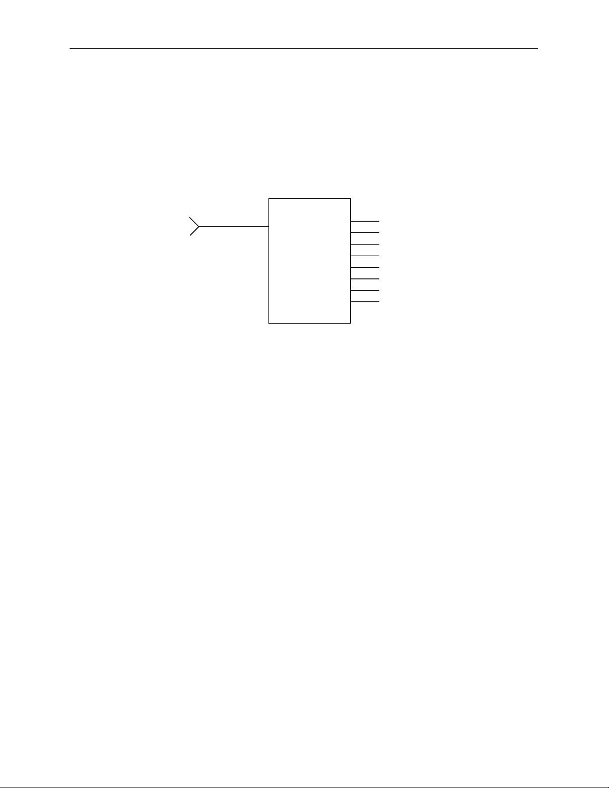
As shown in the block diagrams on the next page, the serial input signal passes through a serial
equalizer circuit where cable equalization and input monitoring is done. This output signal then passes
to a reclocking circuit where the serial input signal is locked to a local serial clock, removing timing
noise and improving jitter performance.
The output of the reclocker circuit feeds into output drivers which provide eight outputs to the rear
BNCs for distribution. The outputs follow the input. For example, when the input is SD, the 8 outputs
are SD. When the input is ASI, ASI outputs for the 7110 are provided at its four non-inverted BNCs (Out
2, Out 4, Out 6 and Out 8). ASI outputs for the 9110 are provided at its four non-inverted BNCs (Out 1,
Out 3, Out 5 and Out 7).
For each module, power is derived from the ± 12 volt frame power. It is regulated to the required +5
volts for the module by an on-board regulator. Each module is fused with a resettable fuse device. If
the fuse opens due to an overcurrent condition, the module will lose power. After pulling the module,
the fuse will reset automatically. No replacement fuse is required.
The on-board CPU can monitor and report module ID information (slot location, software version and
board revision), power status, and ancillary data status to the optional frame System Control module.
This information can be accessed by the user or set to register an alarm if desired using the remote
control options available.
Modules at software version 2.2.0 or later support SNMP (Simple Network Management Protocol)
monitoring. For each applicable signal processing module, module, signal, and reference status are
reported. For complete details on using SNMP monitoring, refer to the Avenue System Overview in the
manual that accompanies each frame.
www.ensembledesigns.com
Page 5
Model 7110 HD/SD/ASI and Model 9110 3G/HD/SD/ASI Reclocking DA
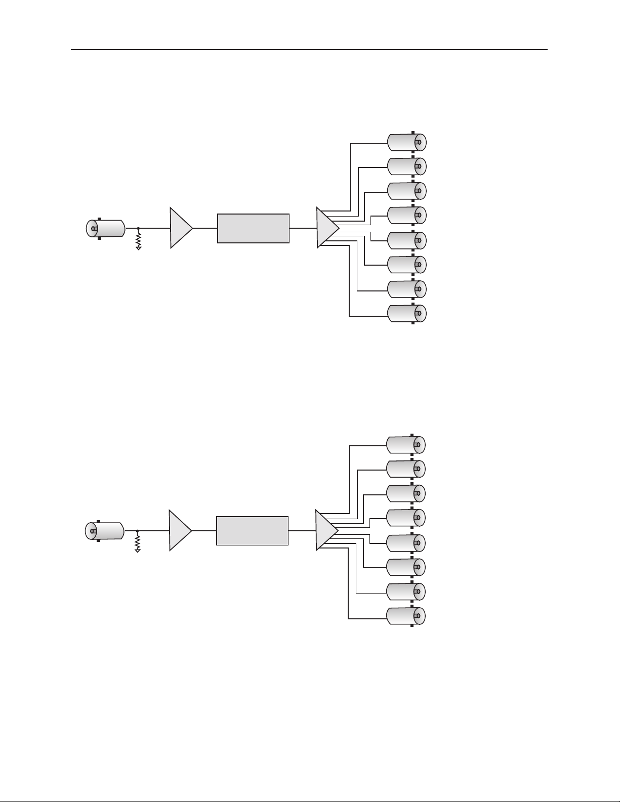
HD/SD/ASI
Input
8 HD/SD Outputs
or
4 ASI Outputs
(follows input)
Reclocker
Automatic
Cable
Equalization
3G/HD/SD/ASI
Input
8 3G/HD/SD Outputs
or
4 ASI Outputs
(follows input)
Reclocker
Automatic
Cable
Equalization
Functional Block Diagrams
7110 HD/SD/ASI Reclocking DA Functional Block Diagram
9110 3G/HD/SD/ASI Reclocking DA Functional Block Diagram
www.ensembledesigns.com
Page 6
Model 7110 HD/SD/ASI and Model 9110 3G/HD/SD/ASI Reclocking DA
Applications
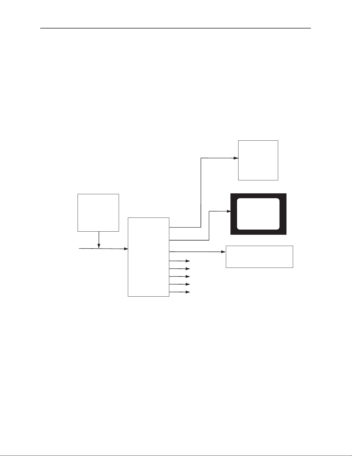
3G High Definition Distribution
You can use the 9110 module to distribute one serial 3G input to eight destinations. The block
diagram below shows a typical example, such as distribution to a 3G monitor, waveform monitoring
equipment, and switcher inputs.
In addition, the 9110 module can distribute a calibrated 3G high definition signal throughout a facility
from a 9400 3G Test Signal Generator when required.
9110
Reclocking
DA
9400 3G TSG
3G Monitor
Waveform Monitor
Other 3G
Destinations
3G
Test
Signal
3G
Signal
3G Switcher
9110 Reclocking DA Application
www.ensembledesigns.com
Page 7
Model 7110 HD/SD/ASI and Model 9110 3G/HD/SD/ASI Reclocking DA
Standard Definition Distribution
You can use the 7110 module to distribute one serial SD input to eight destinations. The signal is
reclocked to reduce noise and jitter and allows distribution to any SD destination. For example,
destinations may include other Avenue modules for video processing, D-to-A conversion, or
embedding or disembedding of audio and many other functions.
7110 SD Reclocking DA Application
SD
Source
Video
7110
Distributed
SD Video
Outputs 1 - 8

www.ensembledesigns.com
Page 8
Model 7110 HD/SD/ASI and Model 9110 3G/HD/SD/ASI Reclocking DA
Installation
Plug the 7110 or 9110 modules into any one of the slots in the 3RU or 1RU frame and install the plastic
overlay provided onto the corresponding group of rear BNC connectors associated with the module
location. Note that the plastic overlay has an optional adhesive backing for securing it to the frame.
Use of the adhesive backing is only necessary if you would like the location to be permanent and is not
recommended if you need to change module locations. These modules may be hot-swapped (inserted
or removed) without powering down or disturbing performance of the other modules in the system.
Cabling
Refer to the 3RU and 1RU backplane diagrams of the module below for cabling instructions. Note that
unless stated otherwise, the 1RU cabling explanations are identical to those given in the 3RU diagram.

www.ensembledesigns.com
Page 9
Model 7110 HD/SD/ASI and Model 9110 3G/HD/SD/ASI Reclocking DA
7110 3RU Backplane
Out 1
Out 3
Out 5
Out 7
HD/SD/ASI In
Out 6
7110 DA
Out 2
Out 4
Out 8
7110 1RU Backplane
If the input is ASI, four
ASI signals are output
at non-inverted BNC
connectors Out 2, Out 4,
Out 6, and Out 8.
Outputs HD or SD
(follows input).
Connect the
distributed signal at
BNCs Out 1 - 8 to HD
or SD destinations.
Connect the HD, SD serial
digital signal or ASI signal to be
distributed to the HD/SD/ASI In
BNC.
7110 DA
Out 8
HD/SD/ASI InOut 5Out 4Out 2 Out 7
Out 6Out 3Out 1
Loading...