

Page 1

Model 9670
LevelTrack Audio Loudness Control
Automatic Gain Control Software
User Guide for Models:
7555, 7660, 7660-XV, 9550, 9550-XA, 9600 and 9600-XV
Family of 3G/HD/SD Embedders, Disembedders, Data Inserters
and Video Processing Frame Synchronizers
Revision 1.5
Page 2
Clearly, Ensemble wants to be in the broadcast equipment business. It’s so rare anymore to nd a company of this
caliber that has not been gobbled up by a large corporation. They are privately held so they don’t have to please the
money people. They really put their eorts into building products and working with customers.
I’m really happy with the Avenue products and Ensemble’s service, and even more important my engineers are happy.
We’ve continued to upgrade the product and add more cards. We will be rebuilding our production control room and
we will use Avenue again.
~ Don McKay, Vice President Engineering, Oregon Public Broadcasting
Who is Ensemble Designs?
By Engineers, For Engineers
In 1989, a former television station engineer who loved
designing and building video equipment, decided to
start a new company. He relished the idea of taking
an existing group of equipment and adding a few
special pieces in order to create an even more elegant
Avenue frames handle 270 Mb/s,
1.5 Gb/s and 3 Gb/s signals,
audio and MPEG signals. Used
worldwide in broadcast, mobile,
production, and post.
ensemble. So, he designed and built his first product and
the company was born.
Focused On What You Need
As the company has grown, more former TV station
engineers have joined Ensemble Designs and this wealth
of practical experience fuels the company’s innovation.
Everyone at the company is focused on providing the
We’re focused on
processing gear–
3G/HD/SD/ASI video,
audio and optical modules.
very equipment you need to complete your ensemble
of video and audio gear. We offer those special pieces
that tie everything together so that when combined, the
whole ensemble is exactly what you need.
Notably Great Service for You
We listen to you – just tell us what you need and we’ll
do our best to build it. We are completely focused on
you and the equipment you need. Being privately held
means we don’t have to worry about a big board of
directors or anything else that might take attention away
from real business. And, you can be sure that when you
call a real person will answer the phone. We love this
business and we’re here to stay.
Bricks and Mortar of Your Facility
The bricks and mortar of a facility include pieces like
up/downconverters, audio embedders, video converters,
routers, protection switches and SPGs for SD, HD and
3Gb/s. That’s what we’re focused on, that’s all we do
– we make proven and reliable signal processing and
infrastructure gear for broadcasters worldwide, for you.
Come on by and visit us.
Drop in for lunch and a tour!
Shipped with care to
television broadcasters
and video facilities all
over the world.
Page 3

LevelTrack™ Audio Loudness Control AGC Software Option
Contents
LevelTrack™ Loudness Control: An Audio Loudness AGC Software Option for Avenue
Systems 5
Overview 5
Software Requirements 6
Configuring LevelTrack Audio Loudness Control AGC 6
Entering the Key 7
Aud Cfg Menu 8
Meter Mode 8
Meter Position 8
Average Time 8
Aud AGC Menu 10
AGC Master 10
Final Gain 10
Silence Limit 10
Target Level 10
Spread 10
Transition Time 11
Max Atten 11
Max Gain 11
Chart 12
Mix 1:4, Mix 5:8, Mix 9:12, Mix 13:16 Menus 13
Combinations of Input Channels 13
AGC Enabled 13
Mix Mode 14
Out Bus Assignments 16
Input/Output Level Control 16
Conguring Audio Output 16
Conguring Digital Audio Outputs 16
www.ensembledesigns.com
Avenue 9670 - page 3
Page 4

LevelTrack™ Audio Loudness Control AGC Software Option
Configuration Example for Calm Act Compliance 17
Typical Settings 17
Troubleshooting 18
The AGC is not being applied to the channel I am monitoring on the chart 18
The Mix Menus in Avenue PC are incomplete or garbled 18
The Mix Menus on the Touch Screen are not responding 18
Thirty-Day Demo 19
Warranty and Factory Service 19
Warranty 19
Factory Service 19
Ensemble White Paper on Dialnorm - Broadcaster
Compliance with the Calm Act 20
Glossary 23
www.ensembledesigns.com
Avenue 9670 - page 4
Page 5

LevelTrack™ Audio Loudness Control AGC Software Option
LevelTrack™ Loudness Control: An Audio Loudness AGC Software Option for Avenue Systems
Overview
The LevelTrack Audio Loudness Control Automatic Gain Control (AGC) Software option adds an
operator configurable audio level management system to Avenue signal processing modules.
LevelTrack Loudness Control will correct mismatched audio levels between different program sources
or segments within a program. Errors of this type are regrettably common due to inconsistencies
between different providers and program elements.
LevelTrack Loudness Control will automatically monitor the levels in up to 16 audio channels. Based
upon the history in each channel, LevelTrack Loudness Control applies gradual changes to prevent
the audio level from dropping below or exceeding user programmable thresholds. The operator can
apply this automatic level control to an individual channel, stereo pair, or a Dolby™ Surround group. By
adjusting the overall level of the signal rather than masking the errors with compression, LevelTrack
Loudness Control will not upset the internal dynamics of the program material.
LevelTrack Loudness Control provides operator control over the following parameters:
• audio target level and spread
• transition time
• maximum gain and attenuation
This flexibility allows the operator to customize LevelTrack Loudness Control to suit the specific audio
level challenges in a particular installation. The operator can adjust all of these parameters through the
Avenue Control System. LevelTrack Loudness Control operates downstream of the manual audio level
adjustments that are already provided in Avenue modules. This allows the automatic feature to assist
the operator when needed without needing to be enabled or disabled.
The LevelTrack Loudness Control product is available through a software license and does not require
any additional hardware.
The following Avenue Modules can be used with LevelTrack Audio Loudness Control AGC Software:
• 7555 HD/SD Video Processing Frame Synchronizer
• 7660 HD/SD Embedder, Disembedder and Data Inserter
• 7660-XV HD/SD Embedder, Disembedder and Data Inserter – Additional Video Outputs
• 9550 3G/HD/SD Video Processing Frame Synchronizer
• 9550-XA 3G/HD/SD Video Processing Frame Synchronizer – Additional Audio Outputs
• 9600 3G/HD/SD Embedder, Disembedder and Data Inserter
• 9600-XV 3G/HD/SD Embedder, Disembedder and Data Inserter – Additional Video Outputs
Note: Modules require software version 2.2.10 or higher and Avenue PC must be version
2.0.15 or higher. Software upgrades are free and can be downloaded from our
website. Please see details in the “Software Requirements” on page 6.
www.ensembledesigns.com
Avenue 9670 - page 5
Page 6

LevelTrack™ Audio Loudness Control AGC Software Option
Software Requirements
Make sure you have installed software version 2.2.10 or higher in your Avenue module (7555, 7660,
7660-XV, 9550, 9550-XA, 9600, 9600-XV) and the latest version of Avenue PC (version 2.0.15 or higher)
in order for LevelTrack Audio Loudness Control AGC Software to function properly. Software updates
are free. You must have a valid serial number for your module and for Avenue PC in order to download
the software.
To download the latest software, go to the following URLs:
http://www.ensembledesigns.com/support/avenue-support/avenue-software
http://www.ensembledesigns.com/support/avenue-support/avenue-pc-software
Configuring LevelTrack Audio Loudness Control AGC
Configuring LevelTrack Audio Loudness Control AGC Software involves the menus in the table
immediately below. Each menu is discussed in greater detail in the subsequent pages in this user
guide.
While the menu examples in this document are taken from the Avenue 9600 Module, these menus and
controls are applicable to other Avenue Modules that are compatible with LevelTrack Audio Loudness
Control AGC Software.
License Menu Use this menu to enter the key provided by Ensemble Designs in
order to activate LevelTrack Audio Loudness Control AGC Software.
See page 7 for details.
Aud Cfg Menu Use this menu to establish settings for the controls Meter Mode
(LKFS or dBFS), Meter Position (pre or post fader) and LKFS or
dBFS Average Time. See page 8 for details.
Aud AGC Menu Use this menu to configure most of the settings for LevelTrack
Loudness Control, including the Audio Target Level, Spread and
Transition Time. See page 10 for details.
Mix 1:4, Mix 5:8, Mix 9:12,
Mix 13:16 Menus
Use these menus to configure how you want the mixer channels to
work with each other and to Enable AGC for specific channels or
associated channels, such as for stereo or Surround Sound. See page
13 for details.
www.ensembledesigns.com
Avenue 9670 - page 6
Page 7
LevelTrack™ Audio Loudness Control AGC Software Option
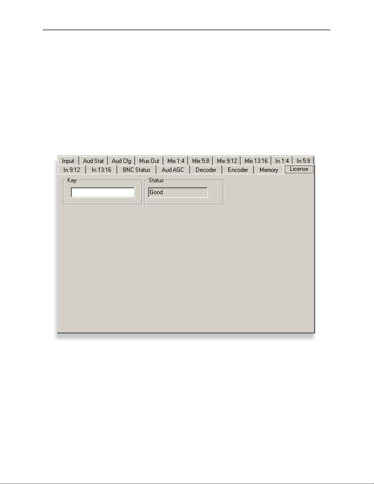
Entering the Key
1. Launch Avenue PC software. (Alternately, the Avenue Touch Screen can be used.)
2. From Avenue PC, select the frame and then the module to display the module’s menus.
3. Select the module’s License menu. The License menu displays.
4. Enter the key provided by Ensemble Designs into the Key field, then press Enter on your keyboard.
If the key you entered is valid, the Status field will display “Good.” If it is invalid, the Status field will
display “Invalid.” If you do not enter a key and press Enter, the Status field will display “None.”
www.ensembledesigns.com
License Avenue PC Menu
Avenue 9670 - page 7
Page 8

LevelTrack™ Audio Loudness Control AGC Software Option
Aud Cfg Menu
Within the Audio Configuration menu, the Meter Mode, Meter Position, and Average Time controls,
discussed on this page, relate specifically to the LevelTrack Loudness Control functionality. For detailed
information regarding the other controls in this menu, please refer to your specific module manual
(7555, 7660 and 7660-XV, 9550 and 9550-XA, 9600 and 9600-XV).
Meter Mode
Select between LKFS and dBFS. This selection determines the method by which the audio is analyzed
and measured, and will impact how Audio AGC behaves.
• LKFS – LKFS (Loudness K-weighted relative to Full Scale) is a loudness amplitude level based on
the ITU-R BS.1770 Loudness Measurement Method. It is a scale for audio measurement similar to
VU or Peak, but rather than measuring gain, it measures perceived loudness. Based on a complex
algorithm, this method takes into account audio processing that increases perceived loudness
without increasing gain. LKFS is the measurement method required to comply with the
Calm Act.
• dBFS – dBFS (Decibels relative to Full Scale) is a more traditional method used for measuring
audio volume. For more information on decibels and dBFS, please refer to the ”Glossary” on page
23.
Meter Position
The Meter Position effects both the Final Average (yellow line) on the AGC chart and the audio input
level for the 9690 Audio Compliance and Monitoring Software. The Meter Position is factory set to
Post.
• Pre (pre-fader) – When Pre is selected, the Final Average (yellow line) on the AGC chart will
not reflect any manual adjustments made in the mixer to the gain level of the channel being
monitored. Similarly, the chart and recording in the 9690 Audio Compliance and Monitoring
Software will reflect the audio input level coming from your source prior to any gain or
attenuation being applied in the mixer.
• Post (post-fader) – When Post is selected, the Final Average (yellow line) on the AGC chart
reflects manual adjustments made in the mixer to the gain level of the channel being monitored.
Similarly, the chart and recording in the 9690 Audio Compliance and Monitoring Software
reflect the audio input level coming from your source after any gain or attenuation is applied in
the mixer.
Average Time
Use this control to set the amount of time used to determine the LKFS or dBFS average. 10 seconds is a
typical setting.
Note: Although the control is labeled ”LKFS Avg Time,” if you have selected dBFS as your
meter mode, the LKFS Avg time control will actually be reflecting dBFS Avg time.
www.ensembledesigns.com
Avenue 9670 - page 8
Page 9

LevelTrack™ Audio Loudness Control AGC Software Option
Aud Cfg Avenue PC Menu
www.ensembledesigns.com
Avenue 9670 - page 9
Page 10

LevelTrack™ Audio Loudness Control AGC Software Option
Aud AGC Menu
The following is a detailed description of the LevelTrack Audio Loudness Control AGC controls and
how they are used:
AGC Master
• Off – When set to Off the LevelTrack Loudness Control AGC functions are turned off. At the
moment that LevelTrack Loudness Control is switched off it will smoothly reduce the gain or
attenuation (if any) that it had been applying.
• On – When set to On, the LevelTrack Loudness Control system engages. It will use the measured
dBFS or LKFS of the incoming signal to determine how much gain or attenuation should be
applied.
Final Gain
This status indicator shows how much correction, either gain or attenuation, the LevelTrack Loudness
Control system is applying.
Silence Limit
0 to -70, factory set to -40 LKFS.
Use this control to establish the value for what is considered to be silence. For example, when set to
the value of -40 LKFS, levels that are at and below that value are treated as silence.
Target Level
0 to -50, factory set to -24 LKFS.
The Target Level setting establishes the target output audio level. The LevelTrack Loudness Control
AGC function will automatically apply gain or attenuation to the signal to bring it within the range
defined by the Target Level and the Spread.
Note: LKFS is interpreted as the inverse of Dialnorm. For example, if your goal is to output
Dialnorm 24, set your Target Level at -24. For more detailed information regarding
Dialnorm and the Calm Act, see “Ensemble White Paper on Dialnorm - Broadcaster
Compliance with the Calm Act” on page 20.
Spread
0 to 50, factory set to 1 LKFS.
Set the Spread from x to x. The Spread indicates how far above and below the Target Level you want
to allow the AGC to go. A typical setting is 1. If, for example, the Target Level is set at -24 LKFS, and the
Spread is set at 1, the AGC will aim to keep the output signal between -25 and -23 LKFS.
www.ensembledesigns.com
Avenue 9670 - page 10
Page 11

LevelTrack™ Audio Loudness Control AGC Software Option
Transition Time
0.5 sec to 30 sec, factory set to 3 seconds.
This setting controls how rapidly LevelTrack Loudness Control will make adjustments once it
determines that a change is needed.
Max Atten
0 dB to -12 dB, factory set to -12 bB.
This control sets the maximum amount of attenuation that LevelTrack Loudness Control can use to
reduce audio levels.
Max Gain
0 dB to +12 dB, factory set to 12 bB.
This control sets the maximum amount of gain that LevelTrack Loudness Control can apply to the
input in order to raise audio levels.
Taken as a whole, these controls provide tremendous flexibility in both how LevelTrack Loudness
Control AGC is configured and in how audio is perceived by the listener.
www.ensembledesigns.com
Aud AGC Avenue PC Menu
Avenue 9670 - page 11
Page 12

LevelTrack™ Audio Loudness Control AGC Software Option
Chart
Click the Chart button to view a visual representation of AGC behavior on a channel-by-channel basis.
The chart represents the most recent two-minute span of time for analysis performed on the channel
selected in the CH Sel drop-down menu.
• In Audio Level (red line): The red line represents the level of the audio signal as it enters the
Avenue module, prior to being processed by AGC.
• Average Level (green line): The green line represents an averaging of the incoming audio signal
level.
• Final Gain (blue line): The blue line represents the Final Gain expressed in terms of decibels (dB).
This shows how much the AGC is adjusting the level of the audio signal based on the configuration
parameters specified in the Aud AGC menu.
• Final Average (yellow line): The yellow line represents the final corrected output, calculated from
the Average Level and the Final Gain. The yellow line reflects manual adjustments made to the
gain level on the mixer for the channel being charted, provided that the Meter Position is set to
Post on the Aud Cfg menu.
• CH Sel drop-down menu: LevelTrack Loudness Control automatically monitors the levels in up to
16 audio channels. From the drop-down menu, select the channel for which you want to view the
LevelTrack Loudness Control AGC behavior.
Note: The Chart’s graph lines remain active as long as you are looking at the corresponding
module on Avenue PC. However, if you keep the chart window open, and then select
a different Avenue module through Avenue PC, the chart’s graph lines will go flat.
AGC is still active, however, until it is turned off in the AGC Master drop-down menu.
Note: The numerical indicators below the chart are labeled as LKFS. If you have selected
dBFS as your Meter Mode in the Aud Config menu, the values will be in dBFS despite
the labels.
www.ensembledesigns.com
Aud AGC Chart
Avenue 9670 - page 12
Page 13

LevelTrack™ Audio Loudness Control AGC Software Option
Mix 1:4, Mix 5:8, Mix 9:12, Mix 13:16 Menus
Combinations of Input Channels
One common method of working with the mixer is to put the signals through unchanged, using
the mixer only to indicate out bus assignments. However, you can also associate channels with one
another by making a selection from the Mix Mode drop-down control, discussed on the next page.
Any particular channel can be independent or it can be tied to other channels. Channels may be
paired or stereo, or grouped for Dolby Surround Sound 5.1 or 7.1. When multiple channels are
associated together, LevelTrack Loudness Control AGC processing (if enabled) takes into account any
channel pairs or Surround Sound groupings.
For modules that have a Dolby E decoder model, any 8 channels may take the input from the Dolby E
decoder, leaving 8 remaining input channels to assign.
AGC Enabled
Enable AGC for any mixer channel by selecting the AGC Enabled box located at the bottom of each
channel. Each AGC Enabled box displays green when enabled and grey when disabled. All channels
that are AGC enabled will be impacted by the AGC.
Note, however, that the AGC Enabled control will have no effect unless AGC is first engaged. To turn
on the AGC function, select On from the AGC Master control in the Aud AGC menu as discussed on
page 10.
Note: At this time, the mixer menus (Mix 1:4, Mix 5:8, Mix 9:12, Mix 13:16) do not function
with the Avenue Touch Screen interface. A pending software update will enable
this control. All mixer functionality is currently available through the Avenue PC
interface. Please be sure you have Avenue PC version 2.0.15 or higher installed.
www.ensembledesigns.com
Mix 1:4 Avenue PC Menu
Avenue 9670 - page 13
Page 14

LevelTrack™ Audio Loudness Control AGC Software Option
Mix Mode
For modules 7555, 7660, 7660-XV, 9550, 9550-XA, 9600 and 9600-XV, the Mix Mode drop-down
control offers four possible selections for how to work with the channels: Normal, Paired, Surround
Sound 5.1, and Surround Sound 7.1. Once you have established a pairing or Surround Sound grouping,
changing the gain on one channel affects all of the associated channels.
AGC processing (if enabled) takes into account any channel pairs or Surround Sound groupings. These
selections are described in the following table:
Mix Mode Mixer Behavior
1. Normal Working with mixer channels independently is the default or “Normal”.
mix mode.
2. Paired If you want two channels to be paired so that altering the gain of one
will automatically alter the gain of the other, choose Paired from the Mix
Mode drop-down control for one of the channels you want to pair; for
example, channel 9 and 10 will be paired with each other if you select
Paired for one of those channels.
3. Surround Sound 5.1 For Surround Sound 5.1, which uses 6 channels, specify for each channel
one of these 6 selections from the Mix Mode drop-down control.
For example:
Input Ch 1 = Multi Left
Input Ch 2 = Multi Right
Input Ch 3 = Multi Center
Input Ch 4 = Multi L Surr
Input Ch 5 = Multi R Surr
Input Ch 6 = Multi Bass
4. Surround Sound 7.1 For Surround Sound 7.1, which uses 8 channels, specify for each channel
one of the above 6 selections plus two additional Mix Mode selections.
For example:
Input Ch 7 = Multi L Rear
Input Ch 8 = Multi R Rear
www.ensembledesigns.com
Avenue 9670 - page 14
Page 15

LevelTrack™ Audio Loudness Control AGC Software Option
Example of Avenue PC Mix 1:4 and Mix 5:8 Menus congured for Dolby Surround Sound
5.1 and a stereo pair.
www.ensembledesigns.com
Avenue 9670 - page 15
Page 16

LevelTrack™ Audio Loudness Control AGC Software Option
Out Bus Assignments
The mixer has 16 input channels and 16 output busses. Initially, each channel is assigned a separate
output bus. For example, by default, mixer input channel 1 is assigned to mixer output bus 1, indicated
by the green button in the Input Ch 1 control. However, you can assign multiple input channels to go
to the same output bus. Or you can have each input channel going to multiple output busses (from 0
to 16).
Input/Output Level Control
Each mixer channel has a level control on its input. There is not a separate output gain level control.
Configuring Audio Output
From the output of the mixer, you can send digital audio out through the 8 AES connectors. Analog
audio is output through the 15-pin D connector. The digital and analog audio paths may be used
simultaneously. You may also re-embed the audio.
Configuring Digital Audio Outputs
Use the Out Bus Assign controls from the Mix 1:4, Mix 5:8, Mix 9:12 and Mix 13:16 menus to route
mixer inputs to mixer outputs. For digital audio, mixer output pair 1/2 feeds SDI out 1/2 and/or AES out
1/2. Mixer output pair 3/4 feeds SDI out 3/4 and/or AES out 3/4, and so on.
Note: If an AES connector is selected as an input, it cannot simultaneously be used as an
output.
www.ensembledesigns.com
Avenue 9670 - page 16
Page 17

LevelTrack™ Audio Loudness Control AGC Software Option
Configuration Example for Calm Act Compliance
Typical Settings
The 9670 LevelTrack Loudness Control Software is factory set to the typical settings used to comply
with the Calm Act, as shown below. The chart shows an example of the AGC behavior with these
settings.
AGC Master On Silence Limit -40 LKFS
Target Level -24 LKFS Spread 1 LKFS
Transition Time 3 sec Max Atten -12 dB
Max Gain 12 LKFS
www.ensembledesigns.com
Avenue 9670 - page 17
Page 18

LevelTrack™ Audio Loudness Control AGC Software Option
Troubleshooting
The AGC is not being applied to the channel I am monitoring on the chart
For LevelTrack Audio Loudness Control AGC to function, the AGC Master must be turned on in the Aud
AGC menu, and the channel(s) that you want AGC applied to must be enabled in the Mix menus.
To turn the AGC Master on, go to the Aud AGC menu and turn the AGC Master control On.
To enable the AGC on a channel by channel basis, go to the Mix menu applicable to the channel(s)
that you want ACG applied to (for example, Channel 4 in Mix menu 1:4). Click the ACG Enable button at
the bottom of the channel(s). The ACG Enable illuminates green when it is enabled and is grey when it
is disabled. LevelTrack Audio Loudness Control AGC can be applied to all or any combination of the 16
audio channels.
The Mix Menus in Avenue PC are incomplete or garbled
Avenue PC Software version 2.0.15 or higher is required to fully support LevelTrack Loudness Control.
Software updates are free at our website. You must have a valid serial number for Avenue PC in order
to download the software.
To download the latest Avenue PC software, go to the following URL:
http://www.ensembledesigns.com/support/avenue-support/avenue-pc-software
The Mix Menus on the Touch Screen are not responding
At this time, the mixer menus (Mix 1:4, Mix 5:8, Mix 9:12, Mix 13:16) do not function with the Avenue
Touch Screen interface. A pending software update will enable this control. However, all mixer
functionality is currently available through the Avenue PC interface. Please be sure you have Avenue
PC version 2.0.15 or higher installed.
www.ensembledesigns.com
Avenue 9670 - page 18
Page 19

LevelTrack™ Audio Loudness Control AGC Software Option
Thirty-Day Demo
AGC provides functionality free for 30 days for demonstration purposes. After 30 days, it requires a
valid key in order to continue working.
Warranty and Factory Service
Warranty
This module is covered by a five-year limited warranty. If you require service (under warranty or not),
please contact Ensemble Designs and ask for customer service before you return the unit. This will
allow the service technician an opportunity to provide any other suggestions for identifying the
problem and to recommend possible solutions.
Factory Service
If you return equipment for repair, please get a Return Material Authorization Number (RMA) from the
factory first.
tel +1 530.478.1830
fax +1 530.478.1832
service@ensembledesigns.com
www.ensembledesigns.com
Ship the product and a written description of the problem to:
Ensemble Designs, Inc.
Attention: Customer Service RMA #####
870 Gold Flat Rd.
Nevada City, CA 95959 USA
Be sure to put your RMA number on the outside of the box.
www.ensembledesigns.com
Avenue 9670 - page 19
Page 20

LevelTrack™ Audio Loudness Control AGC Software Option
Ensemble White Paper on Dialnorm - Broadcaster Compliance with the Calm Act
In December of 2011, Congress enacted and the President signed the “Calm Act” regulating perceived
loudness of programming at broadcast facilities in the U.S. This regulation -based on the ATSC A/85
Recommended Practice: Techniques for Establishing and Maintaining Audio Loudness for Digital
Television – has caused a great deal of confusion in the market place. The key to understanding this
legislation is the phrase “Perceived Loudness”. Perceived loudness goes beyond simple VU gain values
and AGC control. It also takes into account audio processing such as compression, expansion, gating,
limiting, etc., that increases perceived loudness in program audio without increasing gain. The purpose
of this legislation is to maintain consistent audio loudness to the consumer, both between channels
and between programming and commercial content. Broadcasters, satellite providers, cable operators
and other multi channel content providers have until December 2012 to comply. Ensemble Designs
has products that can help broadcasters maintain compliance with the Calm Act.
Perceived loudness compliance is based on Dialog Normalization – dialnorm. Dialnorm is defined in
ATSC A/85 as “An AC-3 metadata parameter, numerically equal to the absolute value of the Dialog
Level, carried in the AC-3 bit stream. This unsigned 5-bit code indicates how far the average Dialog
Level is below 0 LKFS. Valid values are 1-31. (zero value is reserved) The dialnorm values of 1 to 31 are
interpreted as -1 to -31 LKFS.”
To many, LKFS is a relatively new term, which means “Loudness K-weighted relative to Full Scale.”
It’s a scale for audio measurement similar to VU or Peak. However, rather than measuring gain, it’s
measuring loudness. LKFS is based on the ITU-R BS.1770 Loudness Measurement Method. The ITU-R
group performed tests to groups of people around the world with various content and listening
environments and were able to construct an algorithm that accurately measured the loudness of
audio content. It was quite an undertaking, and the details of the process take up the majority of the
BS.1770 document. Have a look sometime. It covers everything from speaker placement to noise in the
environment, to the type of content used for the testing. The loudness unit of LKFS is dB and is used
the same way as a dB of gain. For example, a -15 LKFS program can be made to match the loudness of
a -22 LKFS program by attenuating 7 dB.
There is a defined process for determining the dialnorm value for a particular piece of content. It’s
a fairly involved process depending on whether dialog is present and the length of the sample that
must be used to determine the dialnorm value for the entire program. It can be found in the ATSC
A/85 document if you’d like more detail. Dialnorm relates to the level of an “Anchor Element” which
is usually dialog. It disregards momentary intentional loud elements such as gunshots or car crashes.
Here’s another way to think about this. When you are home watching TV, what do you adjust the
volume to hear? It’s usually the talking part of the program. Sound effects may be louder, whispering
softer. But when you adjust the TV volume, you’re setting it to comfortably hear what’s being spoken.
This is essentially dialnorm. If there is no dialog present, as in music programming, it relates to the
viewer focus element. For example: the level of the featured pianist rather than the level of the entire
orchestra. A single dialnorm value is determined for the entire program content, and is embedded
into the metadata bit stream of the SDI signal. To simplify the process, companies such as Dolby,
Sony, Tektronix and others, have a box that will “listen” to the program content and then report a
dialnorm value for that piece of programming. Another box is often used to encode this value into
the SDI stream. File based content solutions are also available from companies such as Telestream and
Masstech which analyze a particular file’s content and then embeds a dialnorm into the metadata of
the file. All this is well and good for content that is already produced, but what about live productions
www.ensembledesigns.com
Avenue 9670 - page 20
Page 21

LevelTrack™ Audio Loudness Control AGC Software Option
such as sports or news? For this type of programming, a dialnorm target is selected. This is usually
specified by network specs or distributor standard practices. The audio technician then mixes the
audio content to the target dialnorm using LKFS metering. The dialnorm metadata (value) is entered
and encoded into the SDI stream on the fly.
The AC-3 audio system defined in the ATSC Digital Television Standard uses dialnorm metadata to
control loudness and other audio parameters more effectively without permanently altering the
dynamic range of the content. The content provider or DTV operator encodes metadata (the dialnorm
value) along with the audio content into an AC-3 encoder. This metadata parameter, when extracted
at the decoder, sets different content to a uniform loudness transparently. Basically, it provides results
similar to the viewer using his remote control to set a comfortable volume between disparate TV
programs, commercials and channels.
So, what does this mean to the average content distributor who has to comply with the Calm Act?
The FCC is attempting to regulate differences in perceived loudness with particular attention being
paid to inter-channel audio levels; the difference between programming content and commercial
content. In an ideal world, all content providers would provide accurate dialnorm values in the audio
bitstream of their programming. These values, sent to the AC-3 encoder before transmission would
then be decoded at the consumer set top box or flat screen display, which automatically adjusts
“volume” levels at the receiver based on the values received in the metadata. This works by Dynamic
Range Control “gain words” calculated in the encoder and then applied at the decoder. These DRC
calculations are relative to and based on the indicated loudness of content represented by the
dialnorm metadata parameter. In other words, the encoder needs to know how loud the content
is intended to be so it can determine when the content is either “too loud” or “too quiet”. Dialnorm
effectively sets this target. Therefore, it’s very important that the dialnorm accurately indicates the
loudness of the content.
The concept of Fixed metadata is simply to “fix” the AC-3 encoder dialnorm setting to a single value
and to bring the loudness of the encoder audio input signal into conformance with this setting. This is
the simplest method with no requirement for additional metadata equipment or data management. It
is the only approach possible when using an encoder without metadata input or external GPI control.
The Preset metadata concept uses GPI triggers to set predetermined preset values to be loaded into
the AC-3 encoder to accommodate known differences in content loudness. For example, known
differences between network feed and local playout. Some AC-3 encoders however, reset and disrupt
the audio bit stream output when a preset is changed. Depending on the encoder, this may result in
an audible “glitch” on air. To avoid this potential problem, it may be necessary to provide a framesync
for the output of the AC-3 encoder to stabilize the AC-3 source.
The Agile metadata system allows setting different dialnorm values for different content that has
different loudness. This is accomplished by embedding the dialnorm parameter within the metadata
bit stream accompanying the content at an upstream location. The metadata is dis-embedded just
prior to the AC-3 encoder and then connected to the encoder’s external serial metadata input. The
encoder dialnorm setting then changes appropriately on the boundaries of the content. The downside
of the Agile metadata system is the potential for a severe discrepancy in loudness between programs
and between stations if metadata is lost. Encoders with external metadata input provide a “reversion”
feature to mitigate the impact of metadata loss. It can be configured to either retain the most recent
metadata value, or revert to an operator-defined preset. While this feature can minimize the impact on
the consumer, the error in loudness can still be significant. This method requires each piece of content
submitted for broadcast to have its unique dialnorm value embedded into the audio bit stream.
www.ensembledesigns.com
Avenue 9670 - page 21
Page 22

LevelTrack™ Audio Loudness Control AGC Software Option
In the real world, content provided to a broadcaster doesn’t always contain a valid dialnorm value.
Much of the commercial content received at the local level contains none whatsoever. In such cases,
the target loudness value should be -24 LKFS (+/- 2dB). This equates to a dialnorm value of 24.
Broadcasters should be using a BS.1770 metering system to determine proper LKFS values, and all
content received needs to have the dialnorm embedded prior to AC-3 encoding.
Until the “ideal world” becomes a reality, it may be necessary to have a device that maintains audio
levels at a particular dialnorm value, particularly when using a fixed dialnorm metadata AC-3 encoder.
Enter the Ensemble Designs 9670 LevelTrack software key for the Avenue 9600, 9550, 7660 and 7555.
This software uses the BS.1770 loudness algorithm to set a specific LKFS value to be maintained by the
audio stream. As mentioned earlier, this translates directly to a dialnorm value.
Station output audio that is run through one of the Ensemble Designs products with the 9670
software key enabled, can be preset to a specific LKFS value before hitting the fixed dialnorm
metadata EC-3 encoder. As an example, if the encoder has been set for a fixed dialnorm of 24, the
9670 software would be set to -24 LKFS – in effect feeding the encoder an audio loudness dialnorm
equivalent of 24. This allows the broadcaster to use a lower cost encoder and still maintain consistent
loudness levels required by the Calm Act.
The FCC mentions that enforcement of the Calm Act will be complaint driven. If stations show a
consistent pattern of complaints related to audio level disparity, the FCC will investigate. This is
where the Ensemble Designs 9690 Audio Compliance and Monitoring software along with any of the
products mentioned earlier will provide a record of LKFS levels of up to four devices. This record can be
used to prove compliance.
By installing and properly setting up a 7555, 7660, 9550 or 9600 with 9670 software key for LKFS
AGC, and 9690 software key for compliance recording, broadcasters can rest assured that they are in
compliance with the Calm Act, and limit audio loudness complaints by their viewers. That’s a winwin.
Calm Act Update – NAB 2012: The word around NAB this year is that the ATSC A/85 committee will
reconvene shortly to make modifications to the A/85 Recommended Practice for Maintaining Audio
Loudness upon which the Calm Act is based.
Specifically, the committee is meeting to discuss standards for the use of “gating” in LKFS averaging.
This process removes audio below a certain threshold, from the LKFS averaging equation. They will be
meeting to determine exactly where and how the threshold will be implemented.
The problem with the existing spec is that silence is included in the LKFS averaging to determine
dialnorm. This means that if a broadcaster were to air a 30 second spot that is silent – (has no audio),
they are in effect, non-compliant with the CALM Act (+/- 2 dB from average). In addition, the silence
will effect the averaging after audio resumes causing a louder than normal perceived loudness until
proper averaging returns things to normal.
The committee will address these issues. It has an implication to broadcasters and manufacturers alike.
LKFS metering will have to take into account the threshold of the gating before determining overall
LKFS average. File based dialnorm solutions will have to rework their algorithms. Broadcasters of
course, will still have to be in compliance with the Calm Act. All of this has to be done by the December
of this year. Ensemble Designs will be keeping a close eye on these proceedings and will be looking to
make enhancements to our AGC and Compliance software to reflect changes to the spec. Stay tuned.
www.ensembledesigns.com
Avenue 9670 - page 22
Page 23

LevelTrack™ Audio Loudness Control AGC Software Option
Glossary
AES/EBU
The digital audio standard defined as a joint effort of the Audio Engineering Society and the European
Broadcast Union. AES/EBU or AES3 describes a serial bitstream that carries two audio channels,
thus an AES stream is a stereo pair. The AES/EBU standard covers a wide range of sample rates and
quantizations (bit depths). In television systems, these will generally be 48 KHz and either 20 or 24 bits.
AFD
Active Format Description is a method to carry information regarding the aspect ratio of the video
content. The specification of AFD was standardized by SMPTE in 2007 and is now beginning to appear
in the marketplace. AFD can be included in both SD and HD SDI transport systems. There is no legacy
analog implementation. (See WSS).
ASI
A commonly used transport method for MPEG video streams, ASI or Asynchronous Serial Interface,
operates at the same 270 Mb/s data rate as SD SDI. This makes it easy to carry an ASI stream through
existing digital television infrastructure. Known more formally as DVB-ASI, this transport mechanism
can be used to carry multiple program channels.
Aspect Ratio
The ratio of the vertical and horizontal measurements of an image. 4:3 is the aspect ratio for standard
definition video formats and television and 16:9 for high definition. Converting formats of unequal
ratios is done by letterboxing (horizontal bars) or pillar boxing (vertical pillars) in order to keep the
original format’s aspect ratio.
Bandwidth
Strictly speaking, this refers to the range of frequencies (i.e. the width of the band of frequency) used
by a signal, or carried by a transmission channel. Generally, wider bandwidth will carry and reproduce
a signal with greater fidelity and accuracy.
Beta
Sony Beta SP video tape machines use an analog component format that is similar to SMPTE, but
differs in the amplitude of the color difference signals. It may also carry setup on the luminance
channel.
Bit
A binary digit, or bit, is the smallest amount of information that can be stored or transmitted digitally
by electrical, optical, magnetic, or other means. A single bit can take on one of two states: On/Off,
Low/High, Asserted/ Deasserted, etc. It is represented numerically by the numerals 1 (one) and 0
(zero). A byte, containing 8 bits, can represent 256 different states. The binary number 11010111, for
example, has the value of 215 in our base 10 numbering system. When a value is carried digitally, each
additional bit of resolution will double the number of different states that can be represented. Systems
that operate with a greater number of bits of resolution, or quantization, will be able to capture a
www.ensembledesigns.com
Avenue 9670 - page 23
Page 24

LevelTrack™ Audio Loudness Control AGC Software Option
signal with more detail or fidelity. Thus, a video digitizer with 12 bits of resolution will capture 4 times
as much detail as one with 10 bits.
Blanking
The Horizontal and Vertical blanking intervals of a television signal refer to the time periods between
lines and between fields. No picture information is transmitted during these times, which are required
in CRT displays to allow the electron beam to be repositioned for the start of the next line or field.
They are also used to carry synchronizing pulses which are used in transmission and recovery of the
image. Although some of these needs are disappearing, the intervals themselves are retained for
compatibility purposes. They have turned out to be very useful for the transmission of additional
content, such as teletext and embedded audio.
CAV
Component Analog Video. This is a convenient shorthand form, but it is subject to confusion. It is
sometimes used to mean ONLY color difference component formats (SMPTE or Beta), and other times
to include RGB format. In any case, a CAV signal will always require 3 connectors – either Y/R-Y/B-Y,
or R/G/B.
Checkfield
A Checkfield signal is a special test signal that stresses particular aspects of serial digital transmission.
The performance of the Phase Locked-Loops (PLLs) in an SDI receiver must be able to tolerate long
runs of 0’s and 1’s. Under normal conditions, only very short runs of these are produced due to a
scrambling algorithm that is used. The Checkfield, also referred to as the Pathological test signal, will
“undo” the scrambling and cause extremely long runs to occur. This test signal is very useful for testing
transmission paths.
Chroma
The color or chroma content of a signal, consisting of the hue and saturation of the image.
See also Color Difference.
Component
In a component video system, the totality of the image is carried by three separate but related
components. This method provides the best image fidelity with the fewest artifacts, but it requires
three independent transmission paths (cables). The commonly used component formats are
Luminance and Color Difference (Y/Pr/Pb), and RGB. It was far too unwieldy in the early days of color
television to even consider component transmission.
Composite
Composite television dates back to the early days of color transmission. This scheme encodes the
color difference information onto a color subcarrier. The instantaneous phase of the subcarrier is the
color’s hue, and the amplitude is the color’s saturation or intensity. This subcarrier is then added onto
the existing luminance video signal. This trick works because the subcarrier is set at a high enough
frequency to leave spectrum for the luminance information. But it is not a seamless matter to pull
the signal apart again at the destination in order to display it or process it. The resultant artifacts of
dot crawl (also referred to as chroma crawl) are only the most obvious result. Composite television is
www.ensembledesigns.com
Avenue 9670 - page 24
Page 25

LevelTrack™ Audio Loudness Control AGC Software Option
the most commonly used format throughout the world, either as PAL or NTSC. It is also referred to as
Encoded video.
Color Difference
Color Difference systems take advantage of the details of human vision. We have more acuity in our
black and white vision than we do in color. This means that we need only the luminance information to
be carried at full bandwidth, we can scrimp on the color channels. In order to do this, RGB information
is converted to carry all of the luminance (Y is the black and white of the scene) in a single channel.
The other two channels are used to carry the “color difference”. Noted as B-Y and R-Y, these two signals
describe how a particular pixel “differs” from being purely black and white. These channels typically
have only half the bandwidth of the luminance.
Decibel (dB)
The decibel is a unit of measure used to express the ratio in the amplitude or power of two signals. A
difference of 20 dB corresponds to a 10:1 ratio between two signals, 6 dB is approximately a 2:1 ration.
Decibels add while the ratios multiply, so 26 dB is a 20:1 ratio, and 14 dB is a 5:1 ratio. There are several
special cases of the dB scale, where the reference is implied. Thus, dBm refers to power relative to 1
milliwatt, and dBu refers to voltage relative to .775V RMS. The original unit of measure was the Bel
(10 times bigger), named after Alexander Graham Bell.
dBFS
In Digital Audio systems, the largest numerical value that can be represented is referred to as Full
Scale. No values or audio levels greater than FS can be reproduced because they would be clipped.
The nominal operating point (roughly corresponding to 0 VU) must be set below FS in order to have
headroom for audio peaks. This operating point is described relative to FS, so a digital reference level
of -20 dBFS has 20 dB of headroom before hitting the FS clipping point.
DVI
Digital Visual Interface. DVI-I (integrated) provides both digital and analog connectivity. The larger
group of pins on the connector are digital while the four pins on the right are analog.
EDH
Error Detection and Handling is a method to verify proper reception of an SDI or HD-SDI signal at the
destination. The originating device inserts a data packet in the vertical interval of the SDI signal and
every line of the HD signal which contains a checksum of the entire video frame. This checksum is
formed by adding up the numerical values of all of the samples in the frame, using a complex formula.
At the destination this same formula is applied to the incoming video and the resulting value is
compared to the one included in the transmission. If they match, then the content has all arrived with
no errors. If they don’t, then an error has occurred.
Embedded Audio
Digital Audio can be carried along in the same bitstream as an SDI or HD-SDI signal by taking
advantage of the gaps in the transmission which correspond to the horizontal and vertical intervals
of the television waveform. This technique can be very cost effective in transmission and routing, but
can also add complexity to signal handling issues because the audio content can no longer be treated
independently of the video.
www.ensembledesigns.com
Avenue 9670 - page 25
Page 26

LevelTrack™ Audio Loudness Control AGC Software Option
Eye Pattern
To analyze a digital bitstream, the signal can be displayed visually on an oscilloscope by triggering the
horizontal timebase with a clock extracted from the stream. Since the bit positions in the stream form
a very regular cadence, the resulting display will look like an eye – an oval with slightly pointed left and
right ends. It is easy to see from this display if the eye is “open”, with a large central area that is free of
negative or positive transitions, or “closed” where those transitions are encroaching toward the center.
In the first case, the open eye indicates that recovery of data from the stream can be made reliably and
with few errors. But in the closed case data will be difficult to extract and bit errors will occur. Generally
it is jitter in the signal that is the enemy of the eye.
Frame Sync
A Frame Synchronizer is used to synchronize the timing of a video signal to coincide with a timing
reference (usually a color black signal that is distributed throughout a facility). The synchronizer
accomplishes this by writing the incoming video into a frame buffer memory under the timing
direction of the sync information contained in that video. Simultaneously the memory is being read
back by a timing system that is genlocked to a house reference. As a result, the timing or alignment of
the video frame can be adjusted so that the scan of the upper left corner of the image is happening
simultaneously on all sources. This is a requirement for both analog and digital systems in order to
perform video effects or switch glitch-free in a router. Frame synchronization can only be performed
within a single television line standard. A synchronizer will not convert an NTSC signal to a PAL signal,
it takes a standards converter to do that.
Frequency Response
A measurement of the accuracy of a system to carry or reproduce a range of signal frequencies. Similar
to Bandwidth.
H.264
The latest salvo in the compression wars is H.264 which is also known as MPEG-4 Part 10. MPEG-4
promises good results at just half the bit rate required by MPEG-2.
HD
High Definition. This two letter acronym has certainly become very popular. Here we thought it was all
about the pictures – and the radio industry stole it.
HDCP
(High-bandwidth Digital Content Protection) is a content encryption system for HDMI. It is meant to
prevent copyright content from being copied. Protected content, like a movie on a Blu-Ray disc is
encrypted by its creator. Devices that want to display the protected content, like a television, must
have an authorized key in order to decode the signal and display it. The entity that controls the HDCP
standard strictly limits the kinds of devices that are allowed decryption keys. Devices that decrypt the
content and provide an unencrypted copy are not allowed.
www.ensembledesigns.com
Avenue 9670 - page 26
Page 27

LevelTrack™ Audio Loudness Control AGC Software Option
HDMI
The High Definition Multimedia Interface comes to us from the consumer marketplace where it is
becoming the de facto standard for the digital interconnect of display devices to audio and video
sources. It is an uncompressed, all-digital interface that transmits digital video and eight channels of
digital audio. HDMI is a bit serial interface that carries the video content in digital component form
over multiple twisted-pairs. HDMI is closely related to the DVI interface for desktop computers and
their displays.
IEC
The International Electrotechnical Commission provides a wide range of worldwide standards. They
have provided standardization of the AC power connection to products by means of an IEC line cord.
The connection point uses three flat contact blades in a triangular arrangement, set in a rectangular
connector. The IEC specification does not dictate line voltage or frequency. Therefore, the user must
take care to verify that a device either has a universal input (capable of 90 to 230 volts, either 50 or 60
Hz), or that a line voltage switch, if present, is set correctly.
Interlace
Human vision can be fooled to see motion by presenting a series of images, each with a small change
relative to the previous image. In order to eliminate the flicker, our eyes need to see more than 30
images per second. This is accomplished in television systems by dividing the lines that make up
each video frame (which run at 25 or 30 frames per second) into two fields. All of the odd-numbered
lines are transmitted in the first field, the even-numbered lines are in the second field. In this way, the
repetition rate is 50 or 60 Hz, without using more bandwidth. This trick has worked well for years, but
it introduces other temporal artifacts. Motion pictures use a slightly different technique to raise the
repetition rate from the original 24 frames that make up each second of film—they just project each
one twice.
IRE
Video level is measured on the IRE scale, where 0 IRE is black, and 100 IRE is full white. The actual
voltages that these levels correspond to can vary between formats.
ITU-R 601
This is the principal standard for standard definition component digital video. It defines the luminance
and color difference coding system that is also referred to as 4:2:2. The standard applies to both PAL
and NTSC derived signals. They both will result in an image that contains 720 pixels horizontally, with
486 vertical pixels in NTSC, and 576 vertically in PAL. Both systems use a sample clock rate of 27 MHz,
and are serialized at 270 Mb/s.
Jitter
Serial digital signals (either video or audio) are subject to the effects of jitter. This refers to the
instantaneous error that can occur from one bit to the next in the exact position of each digital
transition. Although the signal may be at the correct frequency on average, in the interim it varies.
Some bits come slightly early, others come slightly late. The measurement of this jitter is given
either as the amount of time uncertainty or as the fraction of a bit width. For 270 Mb/s SD video, the
www.ensembledesigns.com
Avenue 9670 - page 27
Page 28

LevelTrack™ Audio Loudness Control AGC Software Option
allowable jitter is 740 picoseconds, or 0.2 UI (Unit Interval – one bit width). For 1.485 Gb/s HD, the
same 0.2UI spec corresponds to just 135 pico seconds.
Luminance
The “black & white” content of the image. Human vision had more acuity in luminance, so television
systems generally devote more bandwidth to the luminance content. In component systems, the
luminance is referred to as Y.
MPEG
The Moving Picture Experts Group is an industry group that develops standards for the compression
of moving pictures for television. Their work is an on-going effort. The understanding of image
processing and information theory is constantly expanding. And the raw bandwidth of both the
hardware and software used for this work is ever increasing. Accordingly, the compression methods
available today are far superior to the algorithms that originally made the real-time compression and
decompression of television possible. Today, there are many variations of these techniques, and the
term MPEG has to some extent become a broad generic label.
Metadata
This word comes from the Greek, meta means ‘beyond’ or ‘after’. When used as a prefix to ‘data’, it can
be thought of as ‘data about the data’. In other words, the metadata in a data stream tells you about
that data – but it is not the data itself. In the television industry, this word is sometimes used correctly
when, for example, we label as metadata the timecode which accompanies a video signal. That
timecode tells you something about the video, i.e. when it was shot, but the timecode in and of itself
is of no interest. But in our industry’s usual slovenly way in matters linguistic, the term metadata has
also come to be used to describe data that is associated with the primary video in a datastream. So
embedded audio will (incorrectly) be called metadata when it tells us nothing at all about the pictures.
Multi-mode
Multi-mode fibers have a larger diameter core than single mode fibers (either 50 or 62.5 microns
compared to 9 microns), and a correspondingly larger aperture. It is much easier to couple light energy
into a multi-mode fiber, but internal reflections will cause multiple “modes” of the signal to propagate
down the fiber. This will degrade the ability of the fiber to be used over long distances.
See also Single Mode.
NTSC
The color television encoding system used in North America was originally defined by the National
Television Standards Committee. This American standard has also been adopted by Canada, Mexico,
Japan, Korea, and Taiwan. (This standard is referred to disparagingly as Never Twice Same Color.)
Optical
An optical interface between two devices carries data by modulating a light source. This light source
is typically a laser or laser diode (similar to an LED) which is turned on and off at the bitrate of the
datastream. The light is carried from one device to another through a glass fiber. The fiber’s core acts
as a waveguide or lightpipe to carry the light energy from one end to another. Optical transmission
has two very significant advantages over metallic copper cables. Firstly, it does not require that the
www.ensembledesigns.com
Avenue 9670 - page 28
Page 29

LevelTrack™ Audio Loudness Control AGC Software Option
two endpoint devices have any electrical connection to each other. This can be very advantageous
in large facilities where problems with ground loops appear. And secondly, and most importantly, an
optical interface can carry a signal for many kilometers or miles without any degradation or loss in the
recovered signal. Copper is barely useful at distances of just 1000 feet.
Oversampling
A technique to perform digital sampling at a multiple of the required sample rate. This has the
advantage of raising the Nyquist Rate (the maximum frequency which can be reproduced by a given
sample rate) much higher than the desired passband. This allows more easily realized anti-aliasing
filters.
PAL
During the early days of color television in North America, European broadcasters developed a
competing system called Phase Alternation by Line. This slightly more complex system is better able
to withstand the differential gain and phase errors that appear in amplifiers and transmission systems.
Engineers at the BBC claim that it stands for Perfection At Last.
Pathological Test Pattern – see Checkfield
Progressive
An image scanning technique which progresses through all of the lines in a frame in a single pass.
Computer monitors all use progressive displays. This contrasts to the interlace technique common to
television systems.
Return Loss
An idealized input or output circuit will exactly match its desired impedance (generally 75 ohms) as a
purely resistive element, with no reactive (capacitive or inductive) elements. In the real world, we can
only approach the ideal. So, our real inputs and outputswill have some capacitance and inductance.
This will create impedance matching errors, especially at higher frequencies. The Return Loss of
an input or output measures how much energy is returned (reflected back due to the impedance
mismatch). For digital circuits, a return loss of 15 dB is typical. This means that the energy returned is
15 dB less than the original signal. In analog circuits, a 40 dB figure is expected.
RGB
RGB systems carry the totality of the picture information as independent Red, Green, and Blue signals.
Television is an additive color system, where all three components add to produce white. Because the
luminance (or detail) information is carried partially in each of the RGB channels, all three must be
carried at full bandwidth in order to faithfully reproduce an image.
ScH Phase
Used in composite systems, ScH Phase measures the relative phase between the leading edge of sync
on line 1 of field 1 and a continuous subcarrier sinewave. Due to the arithmetic details of both PAL and
NTSC, this relationship is not the same at the beginning of each frame. In PAL, the pattern repeats ever
4 frames (8 fields) which is also known as the Bruch Blanking sequence. In NTSC, the repeat is every 2
www.ensembledesigns.com
Avenue 9670 - page 29
Page 30

LevelTrack™ Audio Loudness Control AGC Software Option
frames (4 fields). This creates enormous headaches in editing systems and the system timing of analog
composite facilities.
Setup
In the NTSC Analog Composite standard, the term Setup refers to the addition of an artificial offset
or pedestal to the luminance content. This places the Black Level of the analog signal 54 mV (7.5 IRE)
positive with respect to ground. The use of Setup is a legacy from the early development of television
receivers in the vacuum tube era. This positive offset helped to prevent the horizontal retrace of the
electron beam from being visible on the CRT, even if Brightness and Contrast were mis-adjusted.
While the use of Setup did help to prevent retrace artifacts, it did so at the expense of dynamic range
(contrast) in the signal because the White Level of the signal was not changed.
Setup is optional in NTSC systems, but is never used in PAL systems (see ‘Perfection’ characteristic of
PAL). This legacy of Setup continues to persist in North American NTSC systems, while it has been
abandoned in Japan.
In the digital component world (SD and HD SDI) there is obviously no need for, and certainly every
reason to avoid, Setup. In order for the interfaces between analog and digital systems to operate
as transparently as possible, Setup must be carefully accounted for in conversion products. When
performing analog to digital conversion, Setup (if present) must be removed and the signal range
gained up to account for the 7.5% reduction in dynamic range. And when a digital signal is converted
back to analog form, Setup (if desired on the output) must be created by reducing the dynamic range
by 7.5% and adding the 54 mV positive offset. Unfortunately, there is no truly foolproof algorithm to
detect the presence of Setup automatically, so it’s definitely a case of installer beware.
SDI
Serial Digital Interface. This term refers to inputs and outputs of devices that support serial digital
component video. This could refer to standard definition at 270 Mb/s, HD SDI or High Definition Serial
Digital video at 1.485 Gb/s, or to the newer 3G standard of High Definition video at 2.97 Gb/s.
SMPTE
The Society of Motion Picture and Television Engineers is a professional organization which has done
tremendous work in setting standards for both the film and television industries. The term “SMPTE’” is
also shorthand for one particular component video format - luminance and color difference.
Single Mode
A Single mode (or mono mode) optical fiber carries an optical signal on a very small diameter (9
micron) core surrounded with cladding. The small diameter means that no internally reflected
lightwaves will be propagated. Thus only the original “mode” of the signal passes down the fiber. A
single mode fiber used in an optical SDI system can carry a signal for up to 20 kilometers. Single mode
fibers require particular care in their installation due to the extremely small optical aperture that they
present at splice and connection points. See also Multi-mode.
TBC
www.ensembledesigns.com
Avenue 9670 - page 30
Page 31

LevelTrack™ Audio Loudness Control AGC Software Option
A Time Base Corrector is a system to reduce the Time Base Error in a signal to acceptable levels. It
accomplishes this by using a FIFO (First In, First Out) memory. The incoming video is written into the
memory using its own jittery timing. This operation is closely associated with the actual digitization of
the analog signal because the varying position of the sync timing must be mimicked by the sampling
function of the analog to digital converter. A second timing system, genlocked to a stable reference,
is used to read the video back out of the memory. The memory acts as a dynamically adjusting delay
to smooth out the imperfections in the original signal’s timing. Very often a TBC will also function as a
Frame Synchronizer. See also Frame Sync.
Time Base Error
Time base error is present when there is excessive jitter or uncertainty in the line to line output
timing of a video signal. This is commonly associated with playback from video tape recorders, and
is particularly severe with consumer type heterodyne systems like VHS. Time base error will render a
signal unusable for broadcast or editing purposes.
Timecode
Timecode, a method to uniquely identify and label every frame in a video stream, has become one of
the most recognized standards ever developed by SMPTE. It uses a 24 hour clock, consisting of hours,
minutes, seconds, and television frames. Originally recorded on a spare audio track, this 2400 baud
signal was a significant contributor to the development of video tape editing. We now refer to this as
LTC or Longitudinal Time Code because it was carried along the edge of the tape. This allowed it to
be recovered in rewind and fast forward when the picture itself could not. Timecode continues to be
useful today and is carried in the vertical interval as VITC, and as a digital packet as DVITC. Timecode is
the true metadata.
Tri-Level Sync
For many, many years, television systems used composite black as a genlock reference source. This
was a natural evolution from analog systems to digital implementations. With the advent of High
Definition television, with even higher data rates and tighter jitter requirements, problems with this
legacy genlock signal surfaced. Further, a reference signal with a 50 or 60 Hz frame rate was useless
with 24 Hz HD systems running at film rates. Today we can think of composite black as a bi-level sync
signal – it has two levels, one at sync tip and one at blanking. For HD systems, Tri-Level Sync, which has
the same blanking level (at ground) of bi-level sync, but the sync pulse now has both a negative and
a positive element. This keeps the signal symmetrically balanced so that its DC content is zero. And it
also means that the timing pickoff point is now at the point where the signal crosses blanking and is
no longer subject to variation with amplitude. This makes Tri-Level Sync a much more robust signal
and one which can be delivered with less jitter.
USB
The Universal Serial Bus, developed in the computer industry to replace the previously ubiquitous
RS-232 serial interface, now appears in many different forms and with many different uses. It actually
forms a small local area network, allowing multiple devices to coexist on a single bus where they can
be individually addressed and accessed.
VGA
www.ensembledesigns.com
Avenue 9670 - page 31
Page 32

LevelTrack™ Audio Loudness Control AGC Software Option
Video Graphics Array. Traditional 15-pin, analog interface between a PC and monitor.
Word Clock
Use of Word Clock to genlock digital audio devices developed in the audio recording industry. Early
digital audio products were interconnected with a massive parallel connector carrying a twisted pair
for every bit in the digital audio word. A clock signal, which is a square wave at the audio sampling
frequency, is carried on a 75 ohm coaxial cable. Early systems would daisychain this 44.1 or 48 kilohertz
clock from one device to another with coax cable and Tee connectors. On the rising edge of this Work
Clock these twisted pairs would carry the left channel, while on the falling edge, they would carry the
right channel. In most television systems using digital audio, the audio sample clock frequency (and
hence the ‘genlock’ between the audio and video worlds) is derived from the video genlock signal. But
products that are purely audio, with no video reference capability, may still require Word Clock.
WSS
Wide Screen Signaling is used in the PAL/625 video standards, both in analog and digital form, to
convey information about the aspect ratio and format of the transmitted signal. Carried in the vertical
interval, much like closed captioning, it can be used to signal a television receiver to adjust its vertical
or horizontal sizing to reflect incoming material. Although an NTSC specification for WSS exists, it
never achieved any traction in the marketplace.
YUV
Strictly speaking, YUV does not apply to component video. The letters refer to the Luminance (Y), and
the U and V encoding axes using in the PAL composite system. Since the U axis is very close to the B-Y
axis, and the V axis is very close to the R-Y axis, YUV is often used as a sort of shorthand for the more
long-winded “Y/R-Y/B-Y”.
Y/Cr/Cb
In digital component video, the luminance component is Y, and the two color difference signals are Cr
(R-Y) and Cb (B-Y).
Y/Pr/Pb
In analog component video, the image is carried in three components. The luminance is Y, the R-Y
color difference signal is Pr, and the B-Y color difference signal is Pb.
www.ensembledesigns.com
Avenue 9670 - page 32
 Loading...