

Page 1
Models 9455 and 7435
Clean and Quiet Protection Switches
User Guide
Revision 1.3 SW v1.0.0
Page 2
Clearly, Ensemble wants to be in the broadcast equipment business. It’s so rare anymore to nd a company of this
caliber that has not been gobbled up by a large corporation. They are privately held so they don’t have to please the
money people. They really put their eorts into building products and working with customers.
I’m really happy with the Avenue products and Ensemble’s service, and even more important my engineers are happy.
We’ve continued to upgrade the product and add more cards. We will be rebuilding our production control room and
we will use Avenue again.
~ Don McKay, Vice President Engineering, Oregon Public Broadcasting
Who is Ensemble Designs?
By Engineers, For Engineers
In 1989, a former television station engineer who loved
designing and building video equipment, decided to
start a new company. He relished the idea of taking
an existing group of equipment and adding a few
special pieces in order to create an even more elegant
Avenue frames handle 270 Mb/s,
1.5 Gb/s and 3 Gb/s signals,
audio and MPEG signals. Used
worldwide in broadcast, mobile,
production, and post.
ensemble. So, he designed and built his rst product and
the company was born.
Focused On What You Need
As the company has grown, more former TV station
engineers have joined Ensemble Designs and this wealth
of practical experience fuels the company’s innovation.
Everyone at the company is focused on providing the
We’re focused on
processing gear–
3G/HD/SD/ASI video,
audio and optical modules.
very equipment you need to complete your ensemble
of video and audio gear. We oer those special pieces
that tie everything together so that when combined, the
whole ensemble is exactly what you need.
Notably Great Service for You
We listen to you – just tell us what you need and we’ll
do our best to build it. We are completely focused on
you and the equipment you need. Being privately held
means we don’t have to worry about a big board of
directors or anything else that might take attention away
from real business. And, you can be sure that when you
call a real person will answer the phone. We love this
business and we’re here to stay.
Bricks and Mortar of Your Facility
The bricks and mortar of a facility include pieces like
up/downconverters, audio embedders, video converters,
routers, protection switches and SPGs for SD, HD and
3Gb/s. That’s what we’re focused on, that’s all we do
– we make proven and reliable signal processing and
infrastructure gear for broadcasters worldwide, for you.
Come on by and visit us.
Drop in for lunch and a tour!
Shipped with care to
television broadcasters
and video facilities all
over the world.
Page 3

Model 7435 and 9455 Clean and Quiet Protection Switches
Contents
Module Overview 5
SDI Signal Evaluation 6
Applications 9
Auto-Switched Upconversion Application 9
Fiber Feed Application 9
Front and Rear Lexans 10
Backplane Diagram 11
7435 and 9455 Parameter Table 13
Front Panel Controls and Indicators 15
Avenue PC and Touch Screen Remote Conguration 16
Getting Started 17
Output Menu 17
Status Menu 19
Cong Menu 21
Blk Detect Menu 23
Aud Detect Menu 25
Freeze Menu 27
General Purpose Interface: GPI/GPO 29
23700048 Interface Adapter Cable Drawing and Pinouts 30
GPI Menu 31
GPI Output Jumpers 33
Reference Menu 35
Timing Menu 37
Pri Errors Menu 39
Sec Errors Menu 40
Inputs Menu 41
Memory Menu 43
Software Updates 44
Step by Step Overview for Updating Software in your 9455 or 7435: 45
Detailed Instructions for Updating Software in your 9455 or 7435: 46
IP Adr Menu 46
Subnet Menu 48
www.ensembledesigns.com
7435 and 9455 - page 3
Page 4

Model 7435 and 9455 Clean and Quiet Protection Switches
Troubleshooting 52
Warranty and Factory Service 53
Specications 54
Glossary 55
www.ensembledesigns.com
7435 and 9455 - page 4
Page 5

Model 7435 and 9455 Clean and Quiet Protection Switches
Module Overview
The 9455 and 7435 modules are clean and quiet protection switches for critical broadcast and satellite
feeds. They switch cleanly between asynchronous sources which means they can be used live to air.
Each module has a full video frame synchronizer, rather than a line delay, ensuring perfect alignment
of mis-timed and non-synchronous SDI sources. The 7435 supports 1.5 Gb/s HD SDI and SD SDI signals.
The 9455 additionally supports 3 Gb/s HD SDI.
When a fault is detected in the primary input, and the secondary input is veried as good, the switch
will activate, causing the secondary input to be switched cleanly and quietly to the module’s output.
The 9455 and 7435 include fail-safe bypass which connects the primary input directly to one module
output. This passive, fail-safe path ensures that there is an output even in the event of a total
power failure.
Clean and quiet switching between sources requires that the sources be synchronous and precisely
timed to each other. The 9455 and 7435 accomplish this automatically, with integral frame
synchronization of the inputs, allowing operation with both synchronous and asynchronous (wild)
sources. This frame synchronization feature not only means that the output will always be stable and
glitch-free, but it also means that in the event of a total loss of both inputs, consistently timed color
black will still be output.
The internal frame synchronizers can be genlocked to an external reference signal so that the
output of the 9455 or 7435 is synchronous to local sources. Alternately, in teleports, headends, and
other multi-service facilities, where there is no logical common reference, the module will internally
generate an accurate reference.
The delay through the 9455 or 7435 can be adjusted up to six frames, with independent control for
the primary and secondary input paths. By operating with several frames of delay, the fault detection
algorithms are given enough time to detect a failure in an input signal and switch to the backup
before the fault has actually appeared on-air.
Dierent types of signal testing (vetting) can be enabled on the module. This happens automatically
and independently for the primary and secondary inputs. The health of the video signal is determined
by monitoring crucial parameters in order of increasing complexity; Timing Reference Signal (TRS), or
a persistent loss of digital sync is tested rst. Black, Embedded Audio and Freeze are also evaluated.
Each test can be congured by the user. For example, the sophisticated Black Detector includes
congurable parameters for black level threshold, pixel count, and duration time.
The Freeze detection system can be set to detect a clean or noisy source. Freeze Time sets the number
of seconds for the 9455 or 7435 to switch to the secondary input after a video freeze condition is
detected in the primary input.
The switch can operate in two modes: automatic or nonresetting. In fully automatic mode, the module
will automatically switch back to the primary signal once it’s been restored. In the nonresetting mode,
the secondary input remains routed to the output, even after the primary input has recovered. In this
case manually switching back to the primary is required. If no valid input can be found, consistently
timed color black will be output.
Controls are easily accessed through an Avenue Control Panel, Avenue PC software, GPIs, or front edge
module controls. Software updates for the module are done through a web browser via Ethernet using
the Interface Adapter Cable that comes with the module. This cable provides an Ethernet connection
www.ensembledesigns.com
7435 and 9455 - page 5
Page 6

Model 7435 and 9455 Clean and Quiet Protection Switches
for software upgrades and a 9-pin GPI/GPO connector for control. GPI inputs allow faults detected in
upstream equipment to contribute to the switching logic.
Avenue module parameters can be congured and controlled remotely from one or both of the
remote control options, the Avenue Touch Screen or the Avenue PC Application. Once the module
parameters have been set remotely, the information is stored on the module CPU. This allows the
module be moved to a dierent slot in the frame at your discretion without losing the
stored information.
SDI Signal Evaluation
The 9455/7435 monitors the integrity of the serial digital input stream and analyzes its audio and
video content. HD SDI signal health and fault detection is determined by monitoring any or all of the
following parameters, in order of increasing complexity:
• Timing Reference Signal (TRS) – This parameter checks for the persistent loss of digital sync
by looking for the correct Timing Reference Signal carried in the serial video stream. When this
digital sync format is correct, the signal is considered good.
• Black – Black detection is based on three congurable parameters: black level threshold, black
pixel count, and black duration time. All of these parameters can be set using the menu system
to meet the needs of specic video signal inputs.
• Embedded Audio – This parameter will look for correctly congured embedded audio packets
in the horizontal intervals of the signals. The actual audio content of the packets is further
analyzed to detect silence. Specic audio parameters, such as audio group, silence threshold
level, and audio silence duration can be congured in the Avenue PC and Touch Screen
menus.
• Freeze – This parameter checks for a freeze condition as determined by the settings selected
in the Freeze menu.
A sophisticated black detection system is employed to activate the switch in the event that the signal
is lost. It allows the user to select not only the threshold and percentage of black pixels, but also the
portion of the picture to be considered. The area of the picture checked is determined by selecting
Small Window which is approximately two thirds of the picture width and height, or Big Window
which covers approximately 90% of the width and height. This allows a corner Bug to be either
excluded or included in the detection process.
Black detection is performed on a pixel-by-pixel basis within the selected window, with user selectable
Detect Level and Blk Frac adjustments. Pixels above the Detect Level are considered to be non-black.
Blk Frac sets the percentage of pixels which must be black in order to trigger an error. For example, if
Detect Level is set to 12 IRE and Blk Frac is set to 90%, and Blk Time is set to 3 seconds, then if more
than 90% of the pixels in each frame are below the selected 12 IRE level for a period of 3 seconds, a
switch will occur.
Pri Valid and Sec Valid are dynamic values based on incoming video. In the above example, if Pri
Valid fell below Blk Frac continuously for 3 seconds there would be a switch, provided that there
is valid secondary video. Note however, that the display may not keep pace with short duration
transitions of actual video. In the example, an excursion above 12 IRE for a single frame every 2
seconds would not cause a switch to take place, since the 3 second count would be reinitialized by
these valid frames.
www.ensembledesigns.com
7435 and 9455 - page 6
Page 7
3G/HD/SD
Primary Input
Model 7435 and 9455 Clean and Quiet Protection Switches
Fail-Safe Bypass
9455 Clean and Quiet Protection Switch Block Diagram
Primary Loop Out
Deserializer
Content
Analyzer
Content
Analyzer
Video
Video
Frame
Syncronization
&
Audio SRC
Frame
Synchronization
&
Audio SRC
Module Control System
Decision Arbitration
Output
Formatting
Serializer
Fail-Safe
Out
Output 2
Output 3
Output 4
Output 5
3G/HD/SD
Secondary Input
Ref
Master
Ref
Genlock
Deserializer
Secondary Loop Out
Clocks and Reference
Form C
Relay
Alarm Outputs
GPI Inputs
Ethernet
Backplane
Interface
Sel Pri
Sel Sec
Primary Fail
Secondary Fail
Switch Position
Common
GPI Override Inputs
SNMP/Thumbnails
Avenue System Control
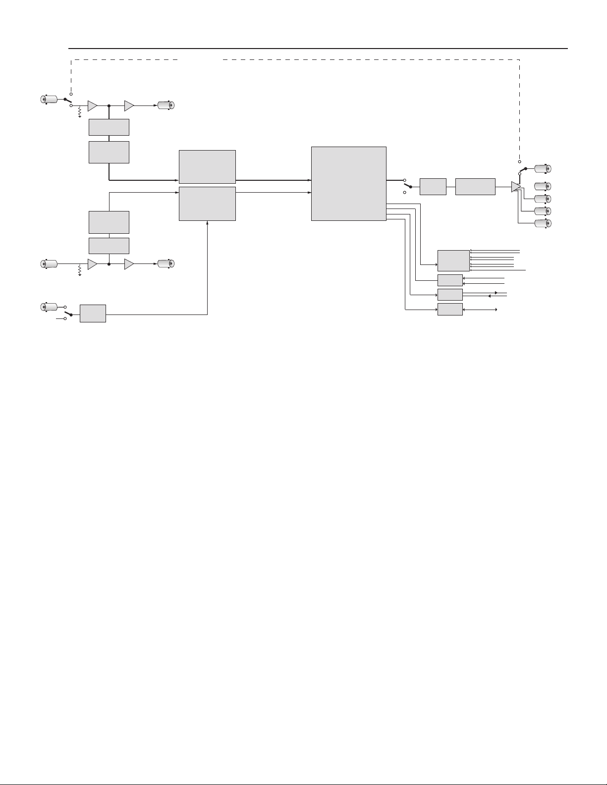
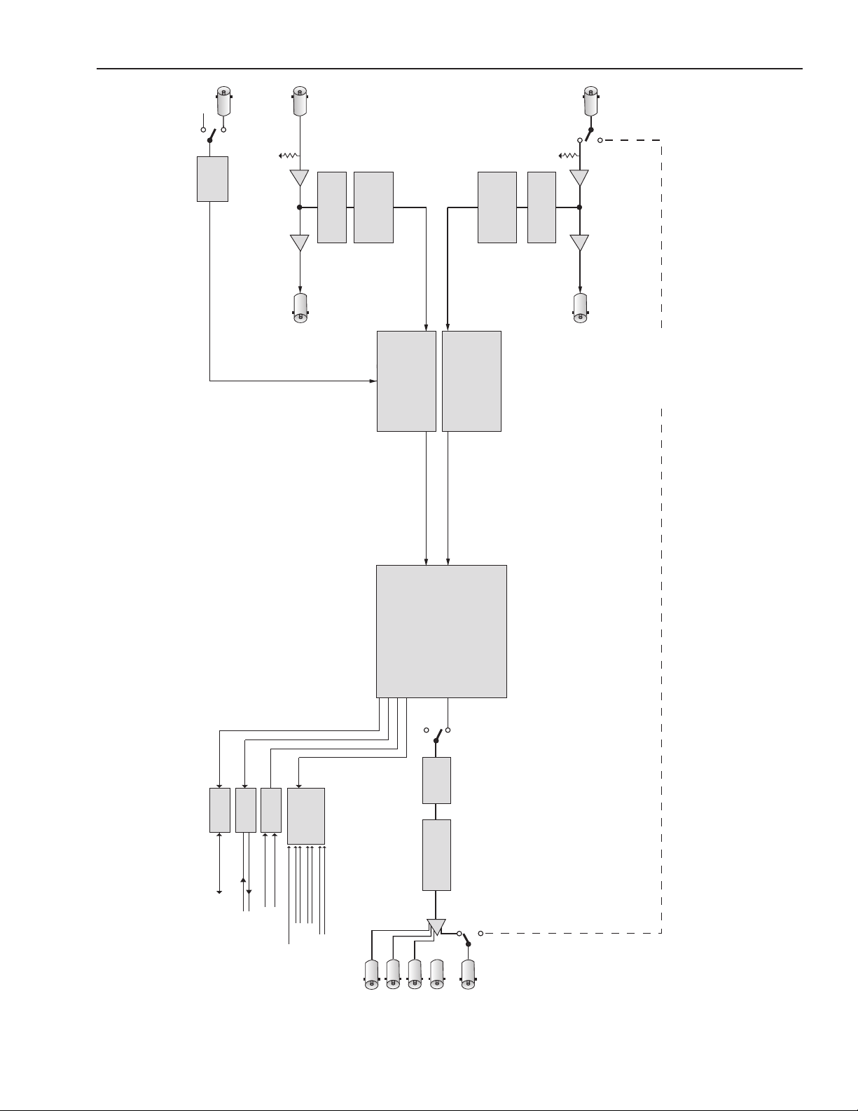
The block diagram, above and on the following page, illustrates the signal ow of the 9455. Note that
in the event of power failure, the passive relay passes the primary input to the Relay Protected Output.
The Primary and Secondary inputs pass through serial digital receiver/equalizers for buering. When
a fault is detected in the Primary input, and the Secondary input is seen as not faulted, the electronic
solid state switch will activate, switching the Secondary input to the output. If both the primary and
the secondary inputs signals are faulted, consistently timed color black will be output.
Each of the signals is fed to identical detection circuits which evaluate multiple parameters
and characteristics of the signal in order to arrive at a fault decision. The output feeds a Field
Programmable Gate Array (FPGA) where the signals are vetted, or tested for congured parameters.
The Signal Vetter™ process in the FPGA detects the parameters chosen by the user through the
Avenue PC or Touch Screen menus. Each of the chosen aspects are monitored independently, and
when they fail to meet the vetted standard, a fault condition is issued.
Fault conditions can be monitored with an external alarm system or other device through the 9-pin
Control connector of the dongle connected to the corresponding 15-pin rear backplane connector.
The Form C relays status outputs from this connector can be monitored by a device to show Primary
and Secondary signal status and the current position of the protect switch (Primary or Secondary).
Two GPI Override Inputs are available to allow changing switch position in response to triggers from
an external source. This can be used to manually reset the switch after the Primary has recovered from
a fault condition or set to respond to a signal state from an external device to trigger a switch.
The on-board CPU can monitor and report module ID information (slot location, software version
and board revision), and power status to the frame System Control module. This information can be
accessed by the user or set to register an alarm if desired using the remote control options available.
Every function and parameter on the module can be controlled from an Avenue Touch Screen Control
Panel or the Avenue PC Control Application. Memory registers can be used to save the complete
conguration of the module, making it easy to change instantly between dierent congurations.
www.ensembledesigns.com
7435 and 9455 - page 7
Page 8
Model 7435 and 9455 Clean and Quiet Protection Switches
Master
Ref
Genlock
Clocks and Reference
9455 Clean and Quiet Protection Switch Block Diagram, landscape view
Note: 7435 does not support 3G but is otherwise identical to the 9455
Secondary Input
Ref
3G/HD/SD
Deserializer
Analyzer
Content
Video
Video
Secondary Loop Out
Primary Input
3G/HD/SD
Analyzer
Deserializer
Content
Primary Loop Out
Synchronization
Audio SRC
Frame
&
Syncronization
Audio SRC
Frame
&
Module Control System
Decision Arbitration
Fail-Safe Bypass
Backplane
Interface
Avenue System Control
GPI Inputs
Ethernet
Sel Sec
GPI Override Inputs
SNMP/Thumbnails
www.ensembledesigns.com
Alarm Outputs
Sel Pri
Switch Position
Common
Form C
Relay
Secondary Fail
Primary Fail
Formatting
Output
Serializer
Output 5
Output 4
Output 3
Output 2
Fail-Safe
Out
7435 and 9455 - page 8
Page 9
Model 7435 and 9455 Clean and Quiet Protection Switches
Alarm Outputs
r
Satellite Uplink
Applications
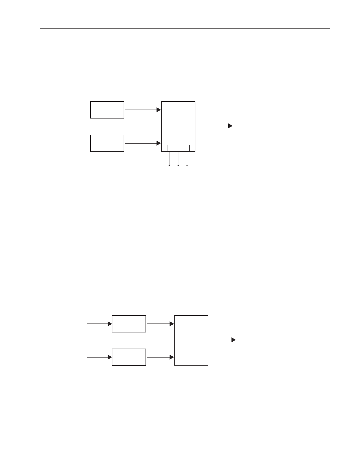
Auto-Switched Upconversion Application
The diagram below shows a typical use for the 7435 module, where it is used to form a fully redundant,
auto-switched conversion chain. The Primary input is backed up with a Secondary input from a video
server. When a switch occurs, the output is always clean switched.
Master
Control
Video
Server
(Backup)
HD SDI
HD SDI
Primary
7435
Clean and Quiet
Protect Switch
Secondary
Control
HD SDI
To Transmitte
Redundant Auto-Switched Conversion with 7435 Module
The 7435 Clean and Quiet Protection Switch accepts HD SDI or SD SDI inputs. For 3G signals, choose
the 9455 Clean and Quiet Protection Switch.
Relay circuits accessible from the 9-pin D Control connector can be connected to alarms for
monitoring Primary and Secondary status and switch position.
Fiber Feed Application
In the example below, a ber feed goes to an Avenue 3720 optical-to-electrical converter and into the
9455. The 9455 evaluates the 3Gb/s HD SDI signal health of both feeds and cleanly switches to the
secondary feed if required.
Fiber
Fiber
Fiber Feed with 9455 Module
www.ensembledesigns.com
3720
O to E
3720
O to E
HD SDI
HD SDI
7435 and 9455 - page 9
Primary
9455
Clean and Quiet
Protect Switch
Secondary
Page 10
Model 7435 and 9455 Clean and Quiet Protection Switches
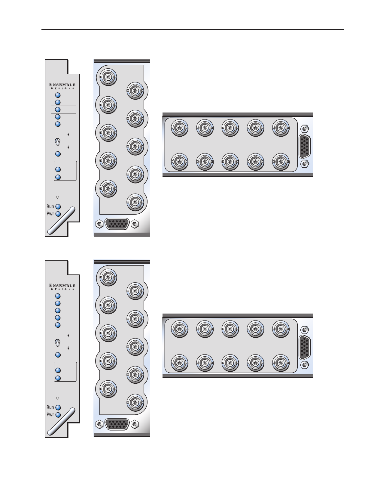
Front and Rear Lexans
9455
/HD/SD
3G
Clean
Switch
Pri
Sec
In OK
Active
Auto
Active
In OK
Local
Control
Ref
Network
Link
Activity
9455 CS
Secondary In
Sec Loop Out
Out 5
Out 4
Out 3
Out 2
Fail-safe Out
Pri Loop Out
Ref In
Primary In
Control
9455 Lexans: front, 3RU rear and 1RU rear
Sec Loop
Out
9455 CS
Out 3
Pri Loop Out
Fail-safe OutOut 5Sec In
Pri InOut 2Out 4
Ref In
Control
7435
/SD
HD
Clean
Switch
Pri
Sec
Network
In OK
Active
Auto
Active
In OK
Local
Control
Ref
Link
Activity
7435 CS
Secondary In
Sec Loop Out
Out 5
Out 4
Out 3
Out 2
Fail-safe Out
Pri Loop Out
Ref In
Primary In
Control
7435 Lexans: front, 3RU rear and 1RU rear
Sec Loop
Out
7435 CS
Out 3
Pri Loop Out
Fail-safe OutOut 5Sec In
Pri InOut 2Out 4
Ref In
Control
www.ensembledesigns.com
7435 and 9455 - page 10
Page 11
Model 7435 and 9455 Clean and Quiet Protection Switches
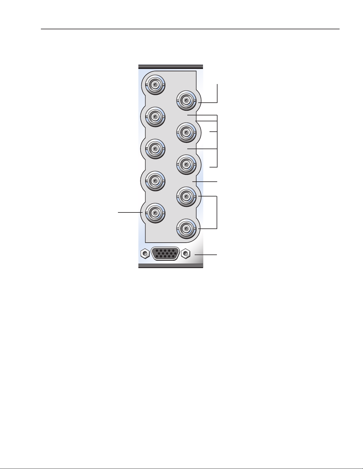
Backplane Diagram
9455 CS
Secondary In
Sec Loop Out
Out 5
Connect the secondary (backup)
digital signal to the Secondary In
BNC and loop the Sec Loop Out
BNC to another destination in the
facility if needed.
Connect NTSC or PAL analog
video, Tri-Level Sync or
10 MHz precision reference to the
Reference In BNC.
Out 4
Out 3
Out 2
Fail-safe Out
Pri Loop Out
Ref In
Primary In
Control
3RU Backplane
Connect the Protect Out
BNCs to destinations.
Connect Fail-safe Out to the
nal destination.
Connect the primary digital
signal to the Primary In BNC
and loop the Pri Loop Out
BNC to another destination in
the facility if necessary.
Connect the 23700048 Interface
Adapter Cable to provide a 9-pin
GPI connector for Control and an
Ethernet connection for software
upgrades. See photo and details on
the following page.
www.ensembledesigns.com
7435 and 9455 - page 11
Page 12
Model 7435 and 9455 Clean and Quiet Protection Switches
23700048 Interface Adapter Cable
The 23700048 Interface Adapter Cable cable connects to the 15 pin D connector on the back of the
Avenue frame that is associated with the clean switch module. The Ethernet port is used for software
upgrades and the 9 pin D connector is used for GPI control.
Software updates are done with a web browser through the Ethernet connection, not thorough
Avenue PC. Please see the “Step by Step Overview for Updating Software in your 9455 or 7435:” on
page 45 for more details.
Please refer to”GPI Menu” on page 31 , and subsequent pages on GPI/GPO for more detailed
information regarding external control.
Connect the male 15 pin D
connector to the female 15
pin D connector on the back
of the frame that corresponds
to the clean switch module
www.ensembledesigns.com
Ethernet for
software
upgrades
7435 and 9455 - page 12
9 pin female D connector for
control. Pinouts and details are
in the GPI section of this manual
beginning on page 28.
Page 13
Model 7435 and 9455 Clean and Quiet Protection Switches
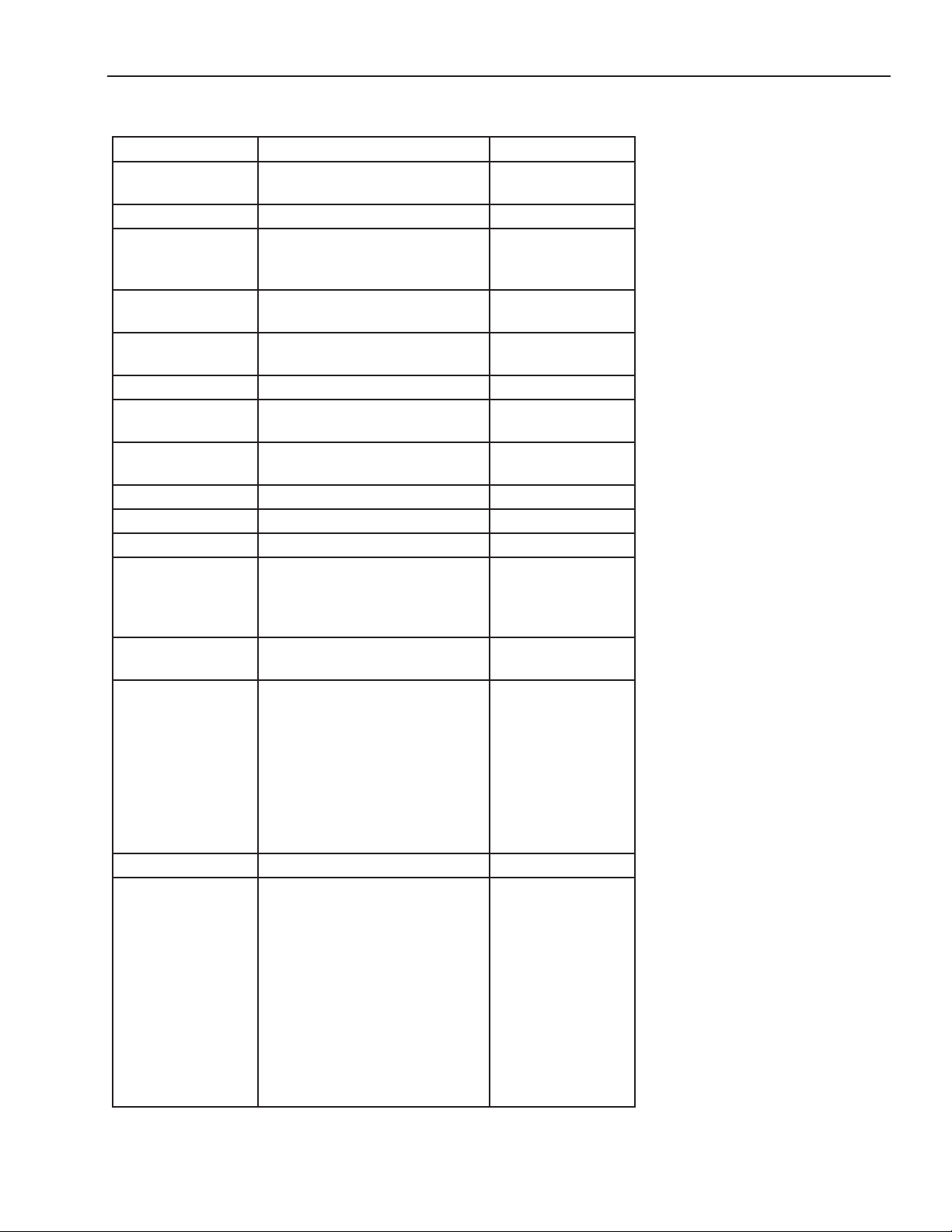
7435 and 9455 Parameter Table
CONTROL AVENUE PC or TOUCH SCREEN DEFAULT
Auto Reset On
O
Reset Time 0 - 120 seconds 15 seconds
TRS Test O
Lenient
Strict
Audio Detect On
O
Black Detect On
O
Freeze Test O On
Sec Test Enable On
O
Window Small
Big
Black Time 0.1 - 300 sec 3 sec
Detect Level 0 - 100 IRE 10 IRE
Black Fraction 0 - 100% 95%
Audio Group Group 1
Group 2
Group 3
Group 4
Group Detect Detect
O
Audio Threshold 0VU
-5 VU
-10 VU
-15 VU
-20 VU
-25 VU
-30 VU
-35 VU
-40 VU
Audio Time .5 - 300 sec 3 sec
Audio Channel
enable
Ch1 enable/disable
Ch2 enable/disable
Ch3 enable/disable
Ch4 enable/disable
Ch5 enable/disable
Ch6 enable/disable
Ch7 enable/disable
Ch8 enable/disable
Ch9 enable/disable
Ch10 enable/disable
Ch11 enable/disable
Ch12 enable/disable
On
Lenient
O
On
On
Big
Group 1
Detect
-20 VU
Enabled
Enabled
Disabled
Disabled
Disabled
Disabled
Disabled
Disabled
Disabled
Disabled
Disabled
Disabled
www.ensembledesigns.com
7435 and 9455 - page 13
Page 14
Model 7435 and 9455 Clean and Quiet Protection Switches
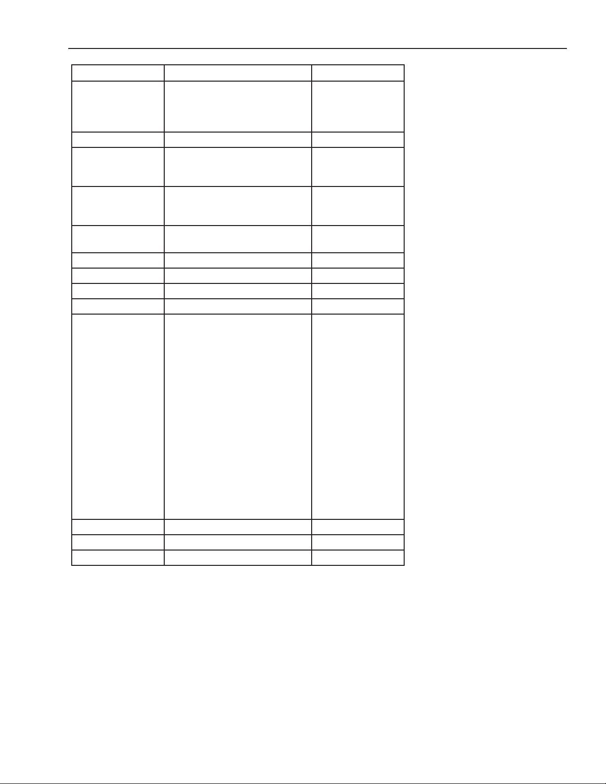
CONTROL AVENUE PC or TOUCH SCREEN DEFAULT
Audio Channel
enable (continued)
Freeze Time 0.1 - 300 sec 3 sec
PRI GPI Mode O
Sec GPI Mode O
Reference Source Master Ref
Frame Delay 1 0 - 6 frames 1
Frame Delay 2 0 - 6 frames 1
Vert Timing -1000 to 1000 lines 0
Hor Timing -1000 to 1000 clocks 0
Output Std 720p/50
IP Address Assignable 192.168.1.100
Sunbnet Mask Assignable 255.255.255.0
Memory Registers 1 - 5 Last Saved
Ch13 enable/disable
Ch14 enable/disable
Ch15 enable/disable
Ch16 enable/disable
Neg Edge Switch
Neg Edge Reg 1
Neg Edge Switch
Neg Edge Reg 2
External
720p/59.94
720p/60
1080i/50
1080i/59.94
1080i/60
1080p/25
1080p/23.98
1080p/24
3G 1080p/50
3G 1080p/59.94
3G 1080p/60
1080sF/25
1080sF/23.98
1080sF/24
SD525
SD625
Disabled
Disabled
Disabled
Disabled
O
O
Master Ref
1080i/59.94
www.ensembledesigns.com
7435 and 9455 - page 14
Page 15
Model 7435 and 9455 Clean and Quiet Protection Switches
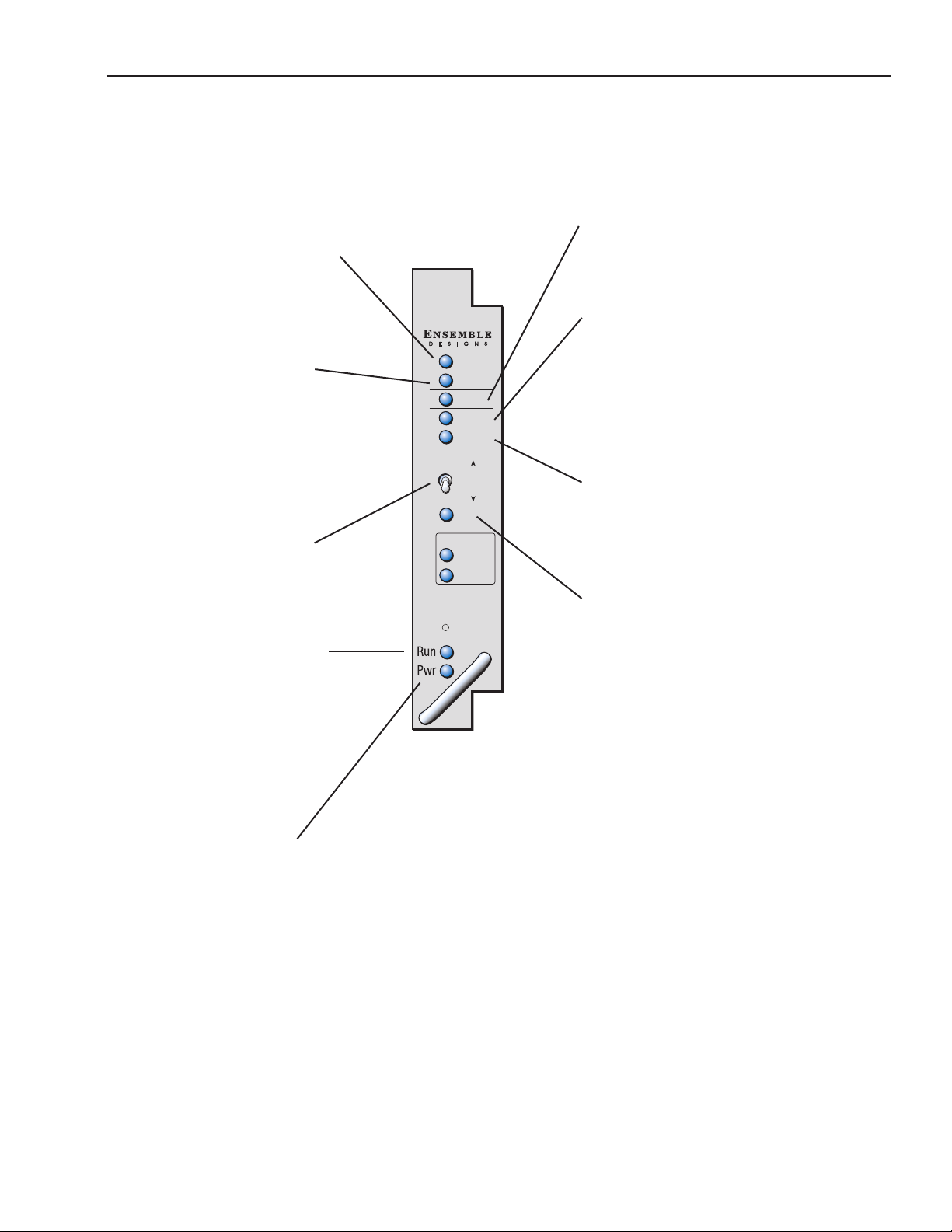
Front Panel Controls and Indicators
Each front edge indicator and switch setting of the 9455 is shown in the diagram below:
Pri In OK green LED:
ON when Primary input passes
all enabled tests.
OFF when Primary input fails an
enabled test.
Pri Active green LED:
ON when Primary input is
feeding the output.
OFF when Primary input is not
feeding the output.
BLINKING when no valid input
is found. The module will output
timed black. Note that the
Secondary Active LED will also
be blinking.
Local Control Switch:
Four position switch used to turn
Auto function ON or OFF, and to
set output to Primary or
Secondary.
Run green LED:
OFF A power fault or halted CPU
ON A halted CPU
FAST BLINK CPU Run error
SLOW BLINK System OK. (If SPI
control is active from the main
frame System Control Module,
all Run indicators will be
synchronized.).
9455
/HD/SD
3G
Clean
Switch
Pri
Sec
In OK
Active
Auto
Active
In OK
Local
Control
Ref
Network
Link
Activity
Auto green LED:
ON when Auto is active.
OFF when Auto is turned o.
Sec Active red LED:
ON when Secondary input is
feeding the output.
OFF when Secondary input is
not feeding the output.
BLINKING when no valid input
is found. The module will output
timed black. Note that the
Primary Active LED will also
be blinking.
Sec In OK green LED:
ON when Secondary input
passes all enabled tests.
OFF when Secondary input fails
an enabled test.
Ref green LED:
ON when locked to a valid
external reference.
OFF when no external reference
is detected.
Pwr green LED:
Indicates the presence (ON) or
absence (OFF) of power.
www.ensembledesigns.com
7435 and 9455 - page 15
Page 16

Model 7435 and 9455 Clean and Quiet Protection Switches
Avenue PC and Touch Screen Remote Conguration
The Avenue PC and Touch Screen remote control status menus for the 9455 and 7435 modules are
illustrated and explained in the following section. Refer to the 9455 and 7435 Parameter Table for
a summary of available parameters that can be set remotely through the menus illustrated. For more
information on using Avenue PC, refer to the Avenue PC Control Application Software data pack that
came with the option. For more information on using Avenue Touch Screen, refer to the Avenue Touch
Screen data pack.
Parameter elds that are grayed out can indicate one of the following conditions:
• An option is not installed.
• The function is not active.
• The module is locked.
• The User Level set with Avenue PC is not accessible from the current User Level.
www.ensembledesigns.com
7435 and 9455 - page 16
Page 17

Model 7435 and 9455 Clean and Quiet Protection Switches
Getting Started
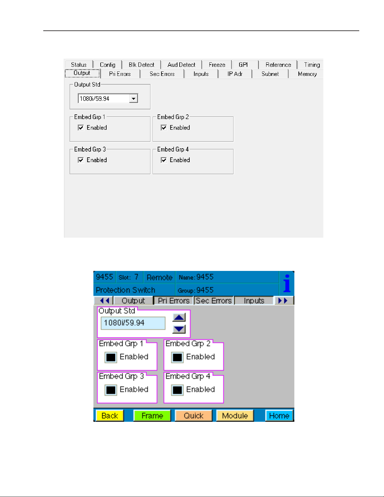
Output Menu
The rst step setting up your clean protection switch is to assign the output standard to the module
in the Output menu. The Output menu screen shown on the following page allows you to select your
output standard, and to enable or disable embedded audio in all four audio Groups.
• Output Std – select the output standard from the following:
720p/50
720p/59.94
720p/60
1080i/50
1080i/59.94
1080i/60
1080p/25
1080p/23.98
1080p/24
3G 1080p/50
3G 1080p/59.94
3G 1080p/60
1080sF/25
1080sF/23.98
1080sF/24
SD525
SD625
The default setting is 1080i/59.94
Note that the output standard selected in this menu must match the input standard of both
the Primary and Secondary inputs. If they output standard does not match the inputs, the
module will output timed black. This will be indicated in the Switch Position reporting
window of the Status Menu. Additionally, on the front panel of the module the Primary Active
and Secondary Active LEDs will blink simultaneously.
• Embed Grp 1, Embed Grp 2, Embed Grp 3, Embed Grp 4 – the default setting and standard
operation for Embed Groups 1 through 4 is enabled. Disable only if you want to strip audio
from the output. When disabled an audio fault will trigger and be indicated in the status menu.
www.ensembledesigns.com
7435 and 9455 - page 17
Page 18
Model 7435 and 9455 Clean and Quiet Protection Switches
Output Avenue PC Menu
www.ensembledesigns.com
Output Touch Screen Menu
7435 and 9455 - page 18
Page 19

Model 7435 and 9455 Clean and Quiet Protection Switches
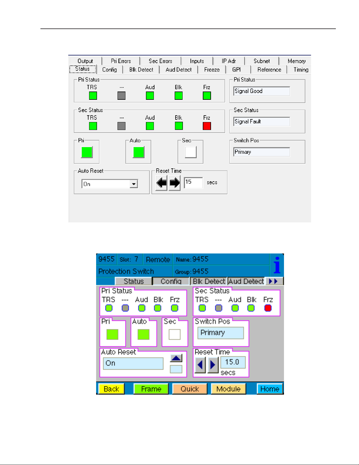
Status Menu
The Status menu screen shown on the following page displays overall status of selected parameters
on both the Primary and Secondary inputs as Green = Good, Red = Bad, Gray = Not enabled. It allows
you to enable or disable the Auto Reset control and to set the Reset Time for the switching function.
In Avenue PC, additional reports are provided for Primary Status and Secondary Status. These two
reports do not appear on the Avenue Touch Screen.
• Pri Status – shows the status of the Primary input’s Timing Reference Signal (TRS), embedded
audio present and correct (Aud), black detected as dened in the Black Detect menu (Blk),
and if frozen video is detected as dened in the Freeze menu (Frz).
In Avenue PC only, the additional Pri Status reporting window to the right will display the
status of the Primary as Signal Good or Signal Fault, and can be monitored with the Avenue
PC alarm function.
• Sec Status – shows the status of the Secondary input’s Timing Reference Signal (TRS),
embedded audio present and correct as dened on the Aud Detect menu (Aud), and black
detected as dened in the Blk Detect menu (Blk), and if frozen video is detected as dened in
the Freeze menu (Frz).
In Avenue PC only, the additional Sec Status reporting window to the right will display the
status of the Secondary as Signal Good or Signal Fault, and can be monitored with the
Avenue PC alarm function.
• Switch Pos – the status window will indicate the current position of the protect switch as
Primary, Secondary or Internal Black. This window can be monitored by the Avenue PC
alarm function.
• Pri – lights green when the Primary input is selected to the output. Click this control to select
the Primary as the output.
• Auto – lights green when Auto is turned on. Switch Auto on and o with this control. When
Auto is on, the module will automatically switch to the Secondary input if the Primary fails and
the Secondary is good.
Note: If the module cannot nd a good signal on the Primary or the Secondary, it will output
consistently timed black. In this situation, both the Primary and Secondary buttons will be
grey and the Switch Position window will report Int Blk. The most likely cause of this is an
incorrectly set Output Format. The Output Format is set in the Output Menu and must match
the format of the Primary and Secondary inputs. The Input Formats are auto detected and
show in the Primary and Secondary Input report windows in the Input Menu.
• Sec – lights red when the Secondary input is selected to the output. Click this control to select
the Secondary as the output.
• Auto Reset – set to On or O to determine if the switch will automatically switch back to the
Primary after it recovers.
• Reset Time – set the amount of time the Primary signal must be good before the Auto Reset
switches back to Primary from Secondary.
www.ensembledesigns.com
7435 and 9455 - page 19
Page 20
Model 7435 and 9455 Clean and Quiet Protection Switches
Status Avenue PC Menu
www.ensembledesigns.com
Status Touch Screen Menu
7435 and 9455 - page 20
Page 21

Model 7435 and 9455 Clean and Quiet Protection Switches
Cong Menu
The Cong menu shown on the following page allows you to congure the TRS Test, and enable or
disable the Audio Detect, Black Detect, Freeze Detect and Secondary Test Enable controls. When the
Audio Detect, Black Detect and/or Freeze Detect are enabled, use their specic menus to set detailed
parameters for each.
• TRS Test – enables the test for any Timing Reference Signal (TRS) errors.
O – sets the input for no TRS test.
Lenient – allows occasional TRS errors to be ignored (10 frames in a row).
Strict – detects any TRS error as a fault.
Default setting is Lenient.
• Audio Detect – enables the test for embedded audio. Use the Aud Detect menu to set the
specic parameters for embedded audio detection.
On – detects an audio condition as determined by the settings made in the Aud Detect
menu.
O – sets the input for no audio test.
Default setting is O.
• Black Detect – enables the test for black detection. Use the Blk Detect menu the to set the
specic parameters for black detection.
On – detects black present as dened by the settings made in the Blk Detect menu.
O – sets the input for no black test.
Default setting is On.
• Freeze Test – enables the test for a freeze condition. Use the Freeze menu the to set the
specic parameters for freeze detection.
On – detects an audio condition as determined by the settings made in the Freeze menu.
O – Set to O for no freeze test.
Default setting is On.
• Sec Test Enable – enables the test for checking the status of the Secondary input.
On – the Secondary status will be checked for the same conguration tests as assigned for
the Primary. On is the recommended setting.
O – no vetting will be performed on the Secondary input.
Default setting is On.
www.ensembledesigns.com
7435 and 9455 - page 21
Page 22

Model 7435 and 9455 Clean and Quiet Protection Switches
Cong Avenue PC Menu
www.ensembledesigns.com
Cong Touch Screen Menu
7435 and 9455 - page 22
Page 23

Model 7435 and 9455 Clean and Quiet Protection Switches
Blk Detect Menu
The Blk Detect menu shown on the following page allows you to congure the black detect
parameters. Select the threshold and percentage of black pixels, the portion of the picture to be
considered, and the amount of time that the signal will be evaluated before a fault is generated.
• Window – select Big or Small. This allows a corner Bug to be either excluded or included in
the detection process.
Big – examines nearly the entire raster, approximately 90% of the width and height.
Small – limits the test to a smaller portion of the raster, approximately two thirds of the
picture width and height (somewhat smaller than Safe Title limits).
Default setting is Big.
• Blk Time – select the amount of time from one frame to 300 seconds that the signal must be
continuously in black before the module switches and alarm is generated.
Default setting is 3 seconds.
• Detect Level – set the video value from 0 to 100 IRE, below which a pixel is considered to be
black.
Default setting is 10 IRE.
• Blk Frac – set the percentage of pixels within the detection window that must be black (as
dened by Detect Level IRE setting) in order to trigger a fault.
Default setting is 95%.
www.ensembledesigns.com
7435 and 9455 - page 23
Page 24

Model 7435 and 9455 Clean and Quiet Protection Switches
Blk Detect Avenue PC Menu
www.ensembledesigns.com
Blk Detect Touch Screen Menu
7435 and 9455 - page 24
Page 25

Model 7435 and 9455 Clean and Quiet Protection Switches
Aud Detect Menu
The Aud Detect menu shown on the following page allows you to congure which groups and
channels are monitored for embedded audio presence, to set the VU levels, to set the silence time
before an alarm is triggered, and to monitor audio status.
The Group Select, Group Detect and Ch1, Ch2, Ch3, Ch4 controls work together as follows:
• Group Select – this pull down allows you to select Group 1, Group 2, Group 3 or Group 4.
Then use the Group Detect control and the Ch1, Ch2, Ch3, Ch4 enable/disable buttons to
dene how you would like the selected group monitored, as described below.
• Group Detect– select Detect or O individually for each of the four embedded audio groups
(Group 1, Group 2, Group 3, Group 4).
• Ch1, Ch2, Ch3, Ch4 – enable or disable monitoring of all 16 audio channels as follows:.
When Group 1 is selected in the Group Select control, the Ch1, Ch2, Ch3, Ch4 enable/disable
buttons represent Channels 1, 2, 3 and 4.
When Group 2 is selected in the Group Select control, the Ch1, Ch2, Ch3, Ch4 enable/disable
buttons represent Channels 5, 6, 7 and 8.
When Group 3 is selected in the Group Select control, the Ch1, Ch2, Ch3, Ch4 enable/disable
buttons represent Channels 9, 10, 11 and 12.
When Group 4 is selected in the Group Select control, the Ch1, Ch2, Ch3, Ch4 enable/disable
buttons represent Channels 13, 14, 15 and 16.
Each embedded group contains four audio channels. Sensing for each channel can be enabled
separately.
• Aud Thrsh – select the silence detection level from 0 VU to –40 VU in 5 VU increments.
Note: An audio signal level of 0 VU corresponds to -20 dBFS and is the generally accepted
digital reference level for AES audio. The 9455 and 7435 use the standard weighting and
ballistics of VU (Volume Unit) measurement rather than decibel-based measurement in order
to more closely represent audio levels as perceived by the listener.
• Audio Time – set the time that the channels must be continuously silent before an alarm
is triggered (0 – 20 seconds). Note that a loss of embedded audio will cause an immediate
switch, regardless of this setting.
The following status displays are also provided:
• Pri Status – shows the status of the four audio channels (of the currently selected Group)
embedded in the Primary signal. Green indicates Channel OK, red indicates silence, and gray
indicates channel not enabled. An OK indicator shows the overall result of the test for all the
channels enabled.
www.ensembledesigns.com
7435 and 9455 - page 25
Page 26

Model 7435 and 9455 Clean and Quiet Protection Switches
• Sec Status – shows the status of the four audio channels (of the currently selected Group)
embedded in the Secondary signal. Green indicates Channel OK, red indicates silence, and
gray indicates channel not enabled. An OK indicator shows the overall result of the test for all
the channels enabled.
• Pri Aud Status – shows the overall status of the audio channels embedded in the Primary
signal. This window can be monitored by the Avenue PC alarm function.
• Sec Aud Status – shows the overall status of the audio channels embedded in the Secondary
signal. This window can be monitored by the Avenue PC alarm function.
www.ensembledesigns.com
Aud Detect Avenue PC Menu
Aud Detect Touch Screen Menu
7435 and 9455 - page 26
Page 27

Model 7435 and 9455 Clean and Quiet Protection Switches
Freeze Menu
The Freeze menu shown on the following page allows you to congure the following parameters for a
video freeze condition:
• Freeze Time – set the amount of time (0.1 to 300 seconds) for the clean switch to switch to the
Secondary input after a video freeze condition is detected.
Default setting is 3 seconds.
The following status indicators can be monitored by Avenue PC alarm functions.
• Pri Frz Status – indicates the freeze status of the Primary as Frozen or Unfrozen.
• Sec Frz Status – indicates the freeze status of the Secondary as Frozen or Unfrozen.
www.ensembledesigns.com
7435 and 9455 - page 27
Page 28

Model 7435 and 9455 Clean and Quiet Protection Switches
Freeze Avenue PC Menu
www.ensembledesigns.com
Freeze Touch Screen Menu
7435 and 9455 - page 28
Page 29

Model 7435 and 9455 Clean and Quiet Protection Switches
General Purpose Interface: GPI/GPO
In addition to full monitoring and access through the control system, 9455 and 7435 modules provide
contact closure status indications. The 9455/7435 can be congured to work with external devices
through the GPI interface via the 23700048 Interface Adapter Cable. The 9455/7435 module’s GPI
output connections can drive an alarm system or other external devices, including LEDs. The module’s
two override GPI inputs are accessed through the 9 pin D connector and are enabled through Avenue
PC software. When the module’s GPI inputs are closed to ground, these overrides will force the switch
to either Primary or Secondary. The GPI inputs are edge-triggered on a negative pulse, or simply a
falling edge. These inputs may also be used to switch back to the Primary after a fault has cleared.
The 23700048 Interface Adapter Cable connects to the 15 pin D connector on the back of the Avenue
frame that is associated with the clean switch module. This cable comes with each clean switch
module and provides a 9 pin D connector for GPI/GPO control, and an Ethernet port for software
upgrades. Please see the photo below as well as the illustrations on the following page for detailed
cable and pinout information.
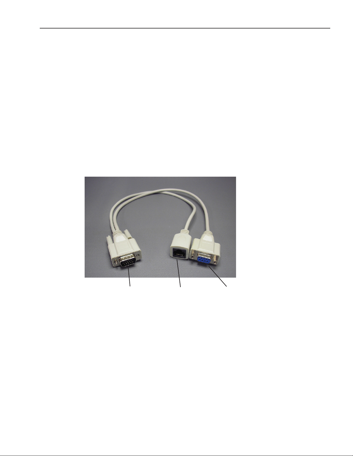
Ensemble Designs p/n 23700048 Interface Adapter Cable, pictured below,
is included with each 9455 and 7435 Clean Protection Switch module.
This “Y” adaptor cable provides a 9-pin D connector for GPI control,
and an Ethernet connection for software upgrades.
Connect the male 15 pin D connector
to the female 15 pin D connector on
the rear of the Avenue frame that
corresponds to the 9455/7435 clean
switch module.
www.ensembledesigns.com
Ethernet
port for
software
upgrades.
7435 and 9455 - page 29
9 pin female D connector
for control. Pinouts
and details are on the
following pages.
Page 30

Model 7435 and 9455 Clean and Quiet Protection Switches
8
Control
976
9 pin female D connector
23700048 Interface Adapter Cable Drawing and Pinouts
Tx+
1
Tx-
2
Rx+
5
Rx-
4
CAT5 compatible twisted
pairs, stranded conductors
J2
RJ45 RECEPTACLE
1
2
NC
NC
NC
NC
3
4
5
6
7
8
1
J2 EXTERNAL VIEW
6
3
PROT_COM
11
PRI_COM
15
SEC_CONTACT
7
SEC_COM
8
PRI_CONTACT
9
PRI-GPI
12
SEC-GPI
14
PROT_CONTACT
10
13
J1
HD15 D-SUB MALE
SHIELD, FOIL, CONNECTED ONLY AT J1, OPEN AT J3
THESE CONDUCTORS 24AWG STRANDED,
ORDINARY SPIRAL LAY, NOT TWISTED PAIRS
ENSEMBLE DESIGNS
P/N 23700048
1
2
3
4
5
6
7
8
9
CONNECTOR
J3
DB9 RECEPTACLE
J3
SHELL
9 Pin Female D
Connector
www.ensembledesigns.com
PIN FUNCTION
15432
1
Gnd
2 Prot Com
3 Pri Com
5
1
4 Sec Contact
5 Sec Com
9
6
6 Pri Contact
7 Pri GPI
8 Sec GPI
9 Prot Contact
7435 and 9455 - page 30
Page 31

Model 7435 and 9455 Clean and Quiet Protection Switches
GPI Menu
The GPI menu screen shown on the following page allows conguration of the two external GPI
inputs. The two Override GPI inputs will force the switch to either Primary or Secondary when closed
to ground. The GPI inputs are edge-triggered on a negative pulse, or simply a falling edge. These
inputs may also be used to switch back to the Primary after a fault has cleared.
The Primary GPI Mode can be set to one of the following:
• O – disables the Primary GPI input, located on pin 7 of the 9 pin female D connector.
• Neg Edge Switch – tells the processor to force to the Primary if ground is input into pin 7 of
the 9 pin female D connector (switches on a low-going transition to the GPI input).
• Neg Edge Reg 1 – tells the processor to switch to the Memory Register 1 presets if ground is
input into pin 7 of the 9 pin female D connector (switches on a low-going transition to the
GPI input).
The Secondary GPI Mode can be set to one of the following:
• O – disables the Secondary GPI input, located on pin 8 of the 9 pin female D connector.
• Neg Edge Switch – tells the processor to force to the Secondary if ground is input into pin 8 of
the 9 pin female D connector (switches on a low-going transition to the GPI input).
• Neg Edge Reg 1 – tells the processor to switch to the Memory Register 1 presets if ground is
input into pin 8 of the 9 pin female D connector (switches on a low-going transition to the
GPI input).
The Pri GPI Status report window indicates the GPI status as either:
• GPI is Low
• GPI is High
The Sec GPI Status report window indicates the GPI status as either:
• GPI is Low
• GPI is High
www.ensembledesigns.com
7435 and 9455 - page 31
Page 32

Model 7435 and 9455 Clean and Quiet Protection Switches
GPI Avenue PC Menu
www.ensembledesigns.com
GPI Touch Screen Menu
7435 and 9455 - page 32
Page 33

Model 7435 and 9455 Clean and Quiet Protection Switches
GPI Output Jumpers
The GPI outputs for the Primary, Secondary and Switch Position are controlled by a series of relays and
jumpers on the module.
The relay contacts provide both NO (Normally Open) and NC (Normally Closed) switching to indicate
fault status of the Primary and Secondary inputs, and the Protection Switch output. Normally Closed
indicates that the signal is good. Select Normally Open (NO) or Normally Closed (NC) via the
2 position headers; H5, H6 and H7 (see illustration below, and details on the following page).
An individual common is provided to each of the relays. For each of the three status relays there is a 3
position header which congures the common signal that will be used by that relay. Each GPI output is
independently strappable to provide Ground, current limited +3.3V (1k resistor), or a Common. Select
Gorund, +3.3 volts or Common via the 3 position headers; H1, H2 and H3 (see illustration below, and
details on the following page).
As an example, with jumpers for the Primary set to NC and +3.3V, the Primary Contact output
(pin 6 of the 9 pin D connector) will source +3.3 volts when the relay is in the normal position,
closed (Signal Good). If the signal fails, the output will be open.
Additionally, in the case of selecting +3.3V as the common, the 1k resistor on the module will act as a
current limiter, allowing the direct connection of ordinary LEDs to each of the output pins. A green
LED could be connected to the Primary Contact output and a red LED to the Protection Contact
output. This would provide complete and explicit indication to the operator as to the signal status and
switch position.
Close up of relay section and associated jumpers on the 9455 module
www.ensembledesigns.com
7435 and 9455 - page 33
Page 34

Model 7435 and 9455 Clean and Quiet Protection Switches
The Primary Jumpers can be set as follows:
• NC or NO – set the jumper on H6 to NC (Normally Closed ) or NO (Normally Open).
Normally Closed indicates that the signal is good.
• GND – uses ground as the relay common. Set the jumper on H1 to the GND (ground) position
to output ground on the Pri Contact pin of the 9 pin female D connector (pin 6).
• +3.3V – provides a +3.3 volt signal through a 1k resistor to the relay common. Set the jumper
on H1 to the +3.3V position to output +3.3 volts on the Pri Contact pin of the 9 pin female D
connector (pin 6).
• COM – uses the user-provided common signal from the Control connector. Use this when
something other than ground or 3.3 volts is needed. Set the jumper on H1 to the COM
(common) position and feed the desired signal into the Pri Com pin (pin 3) of the 9 pin female
D connector. This signal will loop through and be output on the Pri Contact pin (pin 6).
The Secondary Jumpers can be set as follows:
• NC or NO – set the jumper on H7 to NC (Normally Closed ) or NO (Normally Open).
Normally Closed indicates that the signal is good.
• GND – uses ground as the relay common. Set the jumper on H2 to the GND (ground) position
to output ground on the Sec Contact pin of the 9 pin female D connector (pin 4).
• +3.3V – provides a +3.3 volt signal through a 1k resistor to the relay common. Set the jumper
on H2 to the +3.3V position to output +3.3 volts on the Sec Contact pin of the 9 pin female D
connector (pin 4).
• COM – uses the user-provided common signal from the Control connector. Use this when
something other than ground or 3.3 volts is needed. Set the jumper on H2 to the COM
(common) position and feed the desired signal into the Sec Com pin (pin 5) of the 9 pin female
D connector. This signal will loop through and be output on the Sec Contact pin (pin 4).
The Prot Jumpers can be set as follows:
• NC or NO – set the jumper on H5 to NC (Normally Closed ) or NO (Normally Open).
Normally Closed indicates that the switch is in the Primary position.
• GND – uses ground as the relay common. Set the jumper on H3 to the GND (ground) position
to output ground on the Prot Contact pin of the 9 pin female D connector (pin 9).
• +3.3V – provides a +3.3 volt signal through a 1k resistor to the relay common. Set the jumper
on H3 to the +3.3V position to output +3.3 volts on the Prot Contact pin of the 9 pin female D
connector (pin 9).
• COM – uses the user-provided common signal from the Control connector. Use this when
something other than ground or 3.3 volts is needed. Set the jumper on H3 to the COM
(common) position and feed the desired signal into the Prot Com pin (pin 2) of the 9 pin
female D connector. This signal will loop through and be output on the Prot Contact pin
(pin 9).
www.ensembledesigns.com
7435 and 9455 - page 34
Page 35

Model 7435 and 9455 Clean and Quiet Protection Switches
Reference Menu
The module genlocks to either composite video (PAL or NTSC) or to Tri-Level Sync. The module can
lock to the frame’s master reference or reference can be connected directly to the module’s external
Ref In BNC. The Reference menu shown below allows you to select your reference source, and
provides reporting information for the reference status and sync lock.
• Ref Source – select the reference source from Master Ref or External Ref.
If no reference is connected, or the reference fails, the module will switch to it’s own internal
precision reference.
• Ref Status – reports the reference input and status as one of the following:
No Reference
Ref 525
Ref 525 w/VITC
Ref 625
Ref 625 w/VITC
Ref 720p/5994 TLS (note this will be the report for both 720p/59.94 TLS and 720p/60 TLS
Ref 720p/50 TLS
Ref 1080i/5994 TLS (note this will be the report for both 1080i/59.94 TLS and 720p/60 TLS
Ref 1080i/50 TLS
Ref 1080sF/24
Ref 1080p/24
Ref 1080p/25
Ref 10 Mhz
• Sync lock – indicates the sync lock status as one of the following:
Unlocked
Lock 525
Lock 625
Lock TLS
Lock 10M
Lock Internal
*** No Ref ***
www.ensembledesigns.com
7435 and 9455 - page 35
Page 36

Model 7435 and 9455 Clean and Quiet Protection Switches
Reference Avenue PC Menu
www.ensembledesigns.com
Reference Touch Screen Menu
7435 and 9455 - page 36
Page 37

Model 7435 and 9455 Clean and Quiet Protection Switches
Timing Menu
The Timing menu screen shown on the following page allows you to set the amount of additional
delay you would like to add to the Primary and the Secondary, and to adjust the vertical and horizontal
timing.
The delay through the 9455 or 7435 can be adjusted up to six frames, with independent control for
the primary and secondary input paths. By operating with several frames of delay, the fault detection
algorithms are given enough time to detect a failure in an input signal and switch to the backup
before the fault has actually appeared on-air.
• Frame Delay 1 – adjust the amount of delay for the Primary up to 6 frames.
• Frame Delay 2– adjust the amount of delay for the Secondary up to 6 frames.
The Vertical and Horizontal Timing controls adjust the timing of the video signal relative to the timing
reference. Setting the Vertical and Horizontal parameters to 0 (the default setting) will “zero” time the
video signal to the reference. Negative values will cause the video signal to be early with respect to the
reference. Positive values will make the video signal later in time with respect to the reference.
• Vertical Timing – When the Frame Sync is on, adjust the vertical timing of the output signal to
place the leading edge of sync to coincide with other sources.
• Horizontal Timing – When the Frame Sync is on, adjust the horizontal timing of the output
signal to place the leading edge of sync to coincide with other sources.
www.ensembledesigns.com
7435 and 9455 - page 37
Page 38

Model 7435 and 9455 Clean and Quiet Protection Switches
Timing Avenue PC Menu
www.ensembledesigns.com
Timing Touch Screen Menu
7435 and 9455 - page 38
Page 39

Model 7435 and 9455 Clean and Quiet Protection Switches
Pri Errors Menu
The Pri Errors menu shown below displays the amount of time in seconds that each of the error
conditions have been present after detection on the Primary as well as the number of times the
Primary feed has switched to the Secondary feed (Sec Sw Cnt).
The error counters display the number of cumulative errors that have occurred since a counter was
last reset. Errors may occur as a single event, or as multiple events over a period of time. Refer to the
Avenue PC manual to learn how to use the alarms and logging capabilities of Avenue PC to obtain
more detailed information on errors.
The upper limit for cumulative errors is 10,000. If an error counter reaches this upper limit, it will
repeatedly cycle between 10,000 and 9,999. To reset the error counter, double-click it.
Pri Errors Avenue PC Menu
Pri Errors Touch Screen Menu
www.ensembledesigns.com
7435 and 9455 - page 39
Page 40

Model 7435 and 9455 Clean and Quiet Protection Switches
Sec Errors Menu
The Sec Errors menu shown below displays the amount of time in seconds that each of the error
conditions have been present after detection on the Primary as well as the number of times the
Primary feed has switched to the Secondary feed (Sec Sw Cnt).
The error counters display the number of cumulative errors that have occurred since a counter was
last reset. Errors may occur as a single event, or as multiple events over a period of time. Refer to the
Avenue PC manual to learn how to use the alarms and logging capabilities of Avenue PC to obtain
more detailed information on errors.
The upper limit for cumulative errors is 10,000. If an error counter reaches this upper limit, it will
repeatedly cycle between 10,000 and 9,999. To reset the error counter, double-click it.
Sec Errors Avenue PC Menu
Sec Errors Touch Screen Menu
www.ensembledesigns.com
7435 and 9455 - page 40
Page 41

Model 7435 and 9455 Clean and Quiet Protection Switches
Inputs Menu
The Inputs menu shown on the following page displays the type of signal detected on the Primary
and Secondary inputs.
• Primary Input displays the HD SDI signal type detected on the Primary Input connector.
• Secondary Input displays the HD SDI signal type detected on the Secondary Input connector.
9455 and 7435 input choices are:
720p/50
720p/59.94
720p/60
1080i/50
1080i/59.94
1080i/60
1080p/25
1080p/23.98
1080p/24
3G 1080p/50
3G 1080p/59.94
3G 1080p/60
1080sF/25
1080sF/23.98
1080sF/24
SD525
SD625
www.ensembledesigns.com
7435 and 9455 - page 41
Page 42

Model 7435 and 9455 Clean and Quiet Protection Switches
Inputs Avenue PC Menu
www.ensembledesigns.com
Inputs Touch Screen Menu
7435 and 9455 - page 42
Page 43

Model 7435 and 9455 Clean and Quiet Protection Switches
Memory Menu
The Memory menu allows you to save and recall up to 5 dierent setups for the 9455/7435 module as
follows:
• Click Save, then one of the ve memory registers Reg 1 – 5. The box will turn green. The entire
module setup is now saved in the selected register.
• To recall a setup, click the register box. If there is information saved, the box will turn green.
The saved setup will load into the module.
Memory Avenue PC Menu
Memory Touch Screen Menu
www.ensembledesigns.com
7435 and 9455 - page 43
Page 44

Model 7435 and 9455 Clean and Quiet Protection Switches
Software Updates
Software updates for the 9455 and 7435 modules are done via Ethernet. Software updates are free for
life and can be downloaded onto your PC or Mac from the following website:
http://www.ensembledesigns.com/support/avenue-support/avenue-software
Each 9455 and 7435 comes with a “Y” adaptor cable that provides Ethernet and GPI/GPO control. The
23700048 Interface Adapter Cable cable, shown below, connects to the 15 pin D connector associated
with the clean switch module on the back of the Avenue frame. The Ethernet is used for software
upgrades and the 9 pin D connector is used for GPI control.
Software updates are done with a web browser through the Ethernet connection, not thorough
Avenue PC. A synopsis of the steps for updating software is on the following page. Detailed instruction
instructions for updating software in your 9455 or 7435 module follow, including setting the IP address
and subnet mask of the 9455/7435 are on the subsequent pages.
The “Y” adaptor cable pictured below is the
Ensemble Designs p/n 23700048 Interface Adapter Cable.
It provides an Ethernet connection for software upgrades
and a 9-pin GPI connector for control.
Connect the male 15 pin D
connector to the female 15
pin D connector on the back
of the frame that corresponds
to the clean switch module
Ethernet port
for software
upgrades
9 pin female D connector
for control.
www.ensembledesigns.com
7435 and 9455 - page 44
Page 45

Model 7435 and 9455 Clean and Quiet Protection Switches
Step by Step Overview for Updating Software in your 9455 or 7435:
Step 1. Connecting the Cable
Attach the 23700048 Interface Adapter Cable to the 15 pin D connector associated with the clean
switch module on the back of the Avenue frame. Connect an Ethernet cable from the Ethernet port
end of the “Y” cable to your network. The Ethernet port will auto-sense cable direction, so a cross-over
cable is not needed.
Step 2. Setting the IP Address
Use the IP Address menu in Avenue PC or on your Touch Screen to assign a unique IP address to the
9455/7435 module.
Step 3. Setting the Subnet Mask
Use the Subnet menu in Avenue PC or on your Touch Screen to set the subnet mask for the
9455/7435 module.
Step 4. Download Current Software
Download the current software for 9455 or 7435 to your PC or Mac from the following website:
http://www.ensembledesigns.com/support/avenue-support/avenue-software
Step 5. Navigate to your 9455/7435 Module through a Web Browser
On a computer that is networked to the Avenue frame, type the IP address of the 9455/7435 into the
address bar of your web browser. The Setting: General Information window will come up.
Step 6. Update the Module Software
In the Setting: General Information window, click the Choose File button. Navigate to the software that
you downloaded to your computer in Step 4. Click the Start Update button. The Updating Firmware
window will come up. The updating process can take several minutes.
www.ensembledesigns.com
7435 and 9455 - page 45
Page 46

Model 7435 and 9455 Clean and Quiet Protection Switches
Detailed Instructions for Updating Software in your 9455 or 7435:
Updating Software: Step 1. Connecting the Cable
Attach the 23700048 Interface Adapter Cable to the 15 pin D connector associated with the clean
switch module on the back of the Avenue frame. Connect an Ethernet cable from the Ethernet port
end of the “Y” cable to your network. The Ethernet port will auto-sense cable direction, so a cross-over
cable is not needed.
Updating Software: Step 2. Setting the IP Address
Assign a unique IP address to the 9455/7435 module. Use the IP Address menu in Avenue PC or on
your Touch Screen. The IP Address menu is detailed below an illustrated on the following page.
IP Adr Menu
The IP Adr menu shown on the following page allows you to change the IP address of your
94555/7435 module. When you initially power up the 9455 or 7435 as received from the factory, it will
take the self-assigned static IP address of 192.168.1.100. In order to use the Ethernet port to update
module software, you will need to assign anew IP address.
These are general instructions. We recommend that you consult your IT sta if you are uncertain about
any of these network conguration settings.
To Set the IP Address
1. From the IP Adr menu, enter the IP address you want to use that is compatible with your own
network. The simplest method is to touch each number eld, using the keypad to enter the new
numbers. For example, you may want to change the IP address to something like the following:
10.123.222.100. These are general instructions. We recommend that you consult your IT sta if you
are uncertain about any of the network conguration settings.
2. Press Save. Both the Cancel and Save buttons turn black to indicate that your new settings have
been saved.
Note that when using Avenue PC instead of the Touch Screen interface, after entering numbers into
the number elds, you will need to hit the “enter” or “return” key for the change to register.
www.ensembledesigns.com
7435 and 9455 - page 46
Page 47

Model 7435 and 9455 Clean and Quiet Protection Switches
IP Adr Avenue PC Menu
www.ensembledesigns.com
IP Adr Touch Screen Menu
7435 and 9455 - page 47
Page 48

Model 7435 and 9455 Clean and Quiet Protection Switches
Updating Software: Step 3
Set the subnet mask for the 9455/7435 module. Use the Subnet menu in Avenue PC or on your Touch
Screen. The Subnet menu is detailed below an illustrated on the following page.
Subnet Menu
The Subnet menu shown on the following page allows you to change the subnet mask of your
94555/7435 module. In order to use the Ethernet port to update module software, the subnet mask
must be set in accordance with the size and topology of your network. The default setting as received
from the factory is for a smaller network: 255.255.255.0. For a larger network, a typical setting is
255.255.0.0. If in doubt, use the setting for a larger network.
These are general instructions. We recommend that you consult your IT sta if you are uncertain about
any of these network conguration settings.
To Set the Subnet Mask
1. From the Subnet menu, modify the settings as needed. Use the arrow buttons to change the
settings, or touch each number eld to use the keypad.
2. When nished, press Save. Both the Cancel and Save buttons turn black to indicate that your new
settings have been saved.
Note that when using Avenue PC instead of the Touch Screen interface, after entering numbers into
the number elds, you will need to hit the “enter” or “return” key for the change to register.
www.ensembledesigns.com
7435 and 9455 - page 48
Page 49

Model 7435 and 9455 Clean and Quiet Protection Switches
Subnet Avenue PC Menu
www.ensembledesigns.com
Subnet Touch Screen Menu
7435 and 9455 - page 49
Page 50

Model 7435 and 9455 Clean and Quiet Protection Switches
Updating Software: Step 4. Download Current Software
Download the current software for 9455 or 7435 to your PC or Mac from the following website:
http://www.ensembledesigns.com/support/avenue-support/avenue-software
Updating Software: Step 5. Navigate to your 9455/7435 Module through a Web Browser
On a computer that is networked to the Avenue frame, type the IP address of the 9455/7435 into
the address bar of your web browser. The Setting: General Information window will come up, shown
below.
www.ensembledesigns.com
7435 and 9455 - page 50
Page 51

Model 7435 and 9455 Clean and Quiet Protection Switches
Updating Software: Step 6. Update the Module Software
In the Setting: General Information window, click the Choose File button and navigate to the software
that you downloaded to your computer in Step 4. Click the Start Update button. The Updating
Firmware window, shown below, will come up. The updating process can take several minutes.
www.ensembledesigns.com
7435 and 9455 - page 51
Page 52

Model 7435 and 9455 Clean and Quiet Protection Switches
Troubleshooting
As a troubleshooting aid, reference signal status and presence, as well as power and CPU status can be
easily monitored from the front panel of the 9455/7435 module using the front panel indicators.
Refer to the troubleshooting tips below:
Module is outputting black
• Check the Output setting in the Output menu. If the module cannot nd a good signal on
the Primary or the Secondary, it will output consistently timed black. In this situation, both
the Primary and Secondary buttons will be grey and the Switch Position window will report
Int Blk. The most likely cause of this is an incorrectly set Output Format. The Output Format
is set in the Output Menu and must match the format of the Primary and Secondary inputs.
The Input Formats are auto detected and show in the Primary and Secondary Input report
windows in the Input Menu.
Can’t control module
• Check status of CPU Run green LED. Should be blinking slowly and in unison with other
modules if 5030 System Control module is present. If not, try removing the 9455/7435 and
plugging it in again to be sure it is seated properly.
• 5030 System Control module may not be working properly if installed.
Module remote controls are grayed out
• Module is locked or access to module controls is restricted by User Level.
No signal out of module
• Check status of Active LEDs. Primary or Secondary should be lit. If not, check the inputs for
signal presence and quality.
• Check cabling to input of the module.
Please also refer to the technical support section of the Ensemble Designs web site for the latest
information on your equipment at the URL below:
http://www.ensembledesigns.com/support
www.ensembledesigns.com
7435 and 9455 - page 52
Page 53

Model 7435 and 9455 Clean and Quiet Protection Switches
Warranty and Factory Service
Warranty
This module is covered by a ve-year limited warranty, as stated in the main Preface of this manual. If
you require service (under warranty or not), please contact Ensemble Designs and ask for customer
service before you return the unit. This will allow the service technician an opportunity to provide any
other suggestions for identifying the problem and to recommend possible solutions.
Factory Service
If you return equipment for repair, please get a Return Material Authorization Number (RMA) from the
factory rst.
Ship the product and a written description of the problem to:
Ensemble Designs, Inc.
Attention: Customer Service RMA #####
870 Gold Flat Rd.
Nevada City, CA 95959 USA
tel +1 530.478.1830
fax +1 530.478.1832
service@ensembledesigns.com
www.ensembledesigns.com
Be sure to put your RMA number on the outside of the box.
www.ensembledesigns.com
7435 and 9455 - page 53
Page 54

Model 7435 and 9455 Clean and Quiet Protection Switches
Specications
Input
Number Two
Signal Type HD Serial Digital 1.485 Gb/s, SMPTE 274M, 292M or 296M
HD Serial Digital 2.97 Gb/s, SMPTE 424M, 425M (9455 Only)
SD Serial Digital 270 Mb/s, SMPTE 259M
Data, SMPTE 337M
Impedance 75 Ω
Return Loss >15 dB to 1.5 GHz
Max Cable Length 270 Mb/s 300 meters Belden 1694A
1.485 Gb/s 100 meters Belden 1694A
2.97 Gb/s 70 meters Belden 1694A
Automatic Cable Input Equalization
Standards Supported
1080i 50, 59.94 or 60 Hz, SMPTE 274M -4,5,6
720p 50, 59.94 or 60 Hz, SMPTE 296M -1,2,3
1080p 23.98, 24 or 25 Hz, SMPTE 274M -9,10,11
1080p 50, 59.94 Hz, SMPTE 424M, 425M Level A (9455 Only)
1080sF 23.98, 24 or 25 Hz, RP211 -14,15,16
625i 50, 525i 59.94
Serial Digital Loopback
Number Two total
One primary
One secondary
Impedance 75 Ω
Output
Number Six (includes one fail-safe bypass)
Signal Type HD or SD Serial Digital, follows input
Delay Adjustable up to 6 frames
Impedance 75 Ω
Return Loss >15 dB DC to 1.5 GHz
Reference Input
Number One external (modules BNC)
One internal (frame master ref BNC)
Signal Type PAL or NTSC composite video or
Tri-Level Sync
Return Loss >40 dB
General Specifications
Power Consumption 10 watts
Temperature Range 0 to 40°C ambient (all specs met)
Relative Humidity 0 to 95%, noncondensing
Altitude 0 to 10,000 ft
9455 and 7435 modules cannot be installed in slot 3 of a 1RU frame when 5035 System Control module is installed
www.ensembledesigns.com
7435 and 9455 - page 54
Page 55

Model 7435 and 9455 Clean and Quiet Protection Switches
Glossary
AES/EBU
The digital audio standard dened as a joint eort of the Audio Engineering Society and the
European Broadcast Union. AES/EBU or AES3 describes a serial bitstream that carries two audio
channels, thus an AES stream is a stereo pair. The AES/EBU standard covers a wide range of sample
rates and quantizations (bit depths). In television systems, these will generally be 48 KHz and either
20 or 24 bits.
AFD
Active Format Description is a method to carry information regarding the aspect ratio of the video
content. The specication of AFD was standardized by SMPTE in 2007 and is now beginning to
appear in the marketplace. AFD can be included in both SD and HD SDI transport systems. There is no
legacy analog implementation. (See WSS).
ASI
A commonly used transport method for MPEG video streams, ASI or Asynchronous Serial Interface,
operates at the same 270 Mb/s data rate as SD SDI. This makes it easy to carry an ASI stream through
existing digital television infrastructure. Known more formally as DVB-ASI, this transport mechanism
can be used to carry multiple program channels.
Aspect Ratio
The ratio of the vertical and horizontal measurements of an image. 4:3 is the aspect ratio for standard
denition video formats and television and 16:9 for high denition. Converting formats of unequal
ratios is done by letterboxing (horizontal bars) or pillar boxing (vertical pillars) in order to keep the
original format’s aspect ratio.
Bandwidth
Strictly speaking, this refers to the range of frequencies (i.e. the width of the band of frequency) used
by a signal, or carried by a transmission channel. Generally, wider bandwidth will carry and reproduce
a signal with greater delity and accuracy.
Beta
Sony Beta SP video tape machines use an analog component format that is similar to SMPTE, but
diers in the amplitude of the color dierence signals. It may also carry setup on the luminance
channel.
Bit
A binary digit, or bit, is the smallest amount of information that can be stored or transmitted digitally
by electrical, optical, magnetic, or other means. A single bit can take on one of two states: On/O,
Low/High, Asserted/ Deasserted, etc. It is represented numerically by the numerals 1 (one) and
0 (zero). A byte, containing 8 bits, can represent 256 dierent states. The binary number 11010111,
for example, has the value of 215 in our base 10 numbering system. When a value is carried digitally,
each additional bit of resolution will double the number of dierent states that can be represented.
www.ensembledesigns.com
7435 and 9455 - page 55
Page 56

Model 7435 and 9455 Clean and Quiet Protection Switches
Systems that operate with a greater number of bits of resolution, or quantization, will be able to
capture a signal with more detail or delity. Thus, a video digitizer with 12 bits of resolution will
capture 4 times as much detail as one with 10 bits.
Blanking
The Horizontal and Vertical blanking intervals of a television signal refer to the time periods between
lines and between elds. No picture information is transmitted during these times, which are required
in CRT displays to allow the electron beam to be repositioned for the start of the next line or eld.
They are also used to carry synchronizing pulses which are used in transmission and recovery of the
image. Although some of these needs are disappearing, the intervals themselves are retained for
compatibility purposes. They have turned out to be very useful for the transmission of additional
content, such as teletext and embedded audio.
CAV
Component Analog Video. This is a convenient shorthand form, but it is subject to confusion. It is
sometimes used to mean ONLY color dierence component formats (SMPTE or Beta), and other times
to include RGB format. In any case, a CAV signal will always require 3 connectors – either Y/R-Y/B-Y,
or R/G/B.
Checkeld
A Checkeld signal is a special test signal that stresses particular aspects of serial digital transmission.
The performance of the Phase Locked-Loops (PLLs) in an SDI receiver must be able to tolerate long
runs of 0’s and 1’s. Under normal conditions, only very short runs of these are produced due to a
scrambling algorithm that is used. The Checkeld, also referred to as the Pathological test signal, will
“undo” the scrambling and cause extremely long runs to occur. This test signal is very useful for testing
transmission paths.
Chroma
The color or chroma content of a signal, consisting of the hue and saturation of the image.
See also Color Dierence.
Component
In a component video system, the totality of the image is carried by three separate but related
components. This method provides the best image delity with the fewest artifacts, but it requires
three independent transmission paths (cables). The commonly used component formats are
Luminance and Color Dierence (Y/Pr/Pb), and RGB. It was far too unwieldy in the early days of color
television to even consider component transmission.
Composite
Composite television dates back to the early days of color transmission. This scheme encodes the
color dierence information onto a color subcarrier. The instantaneous phase of the subcarrier is the
color’s hue, and the amplitude is the color’s saturation or intensity. This subcarrier is then added onto
the existing luminance video signal. This trick works because the subcarrier is set at a high enough
frequency to leave spectrum for the luminance information. But it is not a seamless matter to pull
the signal apart again at the destination in order to display it or process it. The resultant artifacts of
www.ensembledesigns.com
7435 and 9455 - page 56
Page 57

Model 7435 and 9455 Clean and Quiet Protection Switches
dot crawl (also referred to as chroma crawl) are only the most obvious result. Composite television is
the most commonly used format throughout the world, either as PAL or NTSC. It is also referred to as
Encoded video.
Color Dierence
Color Dierence systems take advantage of the details of human vision. We have more acuity in our
black and white vision than we do in color. This means that we need only the luminance information to
be carried at full bandwidth, we can scrimp on the color channels. In order to do this, RGB information
is converted to carry all of the luminance (Y is the black and white of the scene) in a single channel.
The other two channels are used to carry the “color dierence”. Noted as B-Y and R-Y, these two signals
describe how a particular pixel “diers” from being purely black and white. These channels typically
have only half the bandwidth of the luminance.
Decibel (dB)
The decibel is a unit of measure used to express the ratio in the amplitude or power of two signals. A
dierence of 20 dB corresponds to a 10:1 ratio between two signals, 6 dB is approximately a 2:1 ratio.
Decibels add while the ratios multiply, so 26 dB is a 20:1 ratio, and 14 dB is a 5:1 ratio. There are several
special cases of the dB scale, where the reference is implied. Thus, dBm refers to power relative to
1 milliwatt, and dBu refers to voltage relative to .775V RMS. The original unit of measure was the Bel
(10 times bigger), named after Alexander Graham Bell.
dBFS
In Digital Audio systems, the largest numerical value that can be represented is referred to as Full
Scale. No values or audio levels greater than FS can be reproduced because they would be clipped.
The nominal operating point (roughly corresponding to 0 VU) must be set below FS in order to have
headroom for audio peaks. This operating point is described relative to FS, so a digital reference level
of -20 dBFS has 20 dB of headroom before hitting the FS clipping point.
DVI
Digital Visual Interface. DVI-I (integrated) provides both digital and analog connectivity. The larger
group of pins on the connector are digital while the four pins on the right are analog.
EDH
Error Detection and Handling is a method to verify proper reception of an SDI or HD-SDI signal at the
destination. The originating device inserts a data packet in the vertical interval of the SDI signal and
every line of the HD signal which contains a checksum of the entire video frame. This checksum is
formed by adding up the numerical values of all of the samples in the frame, using a complex formula.
At the destination this same formula is applied to the incoming video and the resulting value is
compared to the one included in the transmission. If they match, then the content has all arrived with
no errors. If they don’t, then an error has occurred.
www.ensembledesigns.com
7435 and 9455 - page 57
Page 58

Model 7435 and 9455 Clean and Quiet Protection Switches
Embedded Audio
Digital Audio can be carried along in the same bitstream as an SDI or HD-SDI signal by taking
advantage of the gaps in the transmission which correspond to the horizontal and vertical intervals
of the television waveform. This technique can be very cost eective in transmission and routing, but
can also add complexity to signal handling issues because the audio content can no longer be treated
independently of the video.
Eye Pattern
To analyze a digital bitstream, the signal can be displayed visually on an oscilloscope by triggering the
horizontal timebase with a clock extracted from the stream. Since the bit positions in the stream form
a very regular cadence, the resulting display will look like an eye – an oval with slightly pointed left and
right ends. It is easy to see from this display if the eye is “open”, with a large central area that is free of
negative or positive transitions, or “closed” where those transitions are encroaching toward the center.
In the rst case, the open eye indicates that recovery of data from the stream can be made reliably and
with few errors. But in the closed case data will be dicult to extract and bit errors will occur. Generally
it is jitter in the signal that is the enemy of the eye.
Frame Sync
A Frame Synchronizer is used to synchronize the timing of a video signal to coincide with a timing
reference (usually a color black signal that is distributed throughout a facility). The synchronizer
accomplishes this by writing the incoming video into a frame buer memory under the timing
direction of the sync information contained in that video. Simultaneously the memory is being read
back by a timing system that is genlocked to a house reference. As a result, the timing or alignment of
the video frame can be adjusted so that the scan of the upper left corner of the image is happening
simultaneously on all sources. This is a requirement for both analog and digital systems in order to
perform video eects or switch glitch-free in a router. Frame synchronization can only be performed
within a single television line standard. A synchronizer will not convert an NTSC signal to a PAL signal,
it takes a standards converter to do that.
Frequency Response
A measurement of the accuracy of a system to carry or reproduce a range of signal frequencies.
Similar to Bandwidth.
H.264
The latest salvo in the compression wars is H.264 which is also known as MPEG-4 Part 10. MPEG-4
promises good results at just half the bit rate required by MPEG-2.
HD
High Denition. This two letter acronym has certainly become very popular. Here we thought it was all
about the pictures – and the radio industry stole it.
HDMI
The High Denition Multimedia Interface comes to us from the consumer marketplace where it is
becoming the de facto standard for the digital interconnect of display devices to audio and video
www.ensembledesigns.com
7435 and 9455 - page 58
Page 59

Model 7435 and 9455 Clean and Quiet Protection Switches
sources. It is an uncompressed, all-digital interface that transmits digital video and eight channels of
digital audio. HDMI is a bit serial interface that carries the video content in digital component form
over multiple twisted-pairs. HDMI is closely related to the DVI interface for desktop computers and
their displays.
IEC
The International Electrotechnical Commission provides a wide range of worldwide standards. They
have provided standardization of the AC power connection to products by means of an IEC line cord.
The connection point uses three at contact blades in a triangular arrangement, set in a rectangular
connector. The IEC specication does not dictate line voltage or frequency. Therefore, the user must
take care to verify that a device either has a universal input (capable of 90 to 230 volts, either 50 or
60 Hz), or that a line voltage switch, if present, is set correctly.
Interlace
Human vision can be fooled to see motion by presenting a series of images, each with a small change
relative to the previous image. In order to eliminate the icker, our eyes need to see more than 30
images per second. This is accomplished in television systems by dividing the lines that make up
each video frame (which run at 25 or 30 frames per second) into two elds. All of the odd-numbered
lines are transmitted in the rst eld, the even-numbered lines are in the second eld. In this way, the
repetition rate is 50 or 60 Hz, without using more bandwidth. This trick has worked well for years, but
it introduces other temporal artifacts. Motion pictures use a slightly dierent technique to raise the
repetition rate from the original 24 frames that make up each second of lm—they just project each
one twice.
IRE
Video level is measured on the IRE scale, where 0 IRE is black, and 100 IRE is full white. The actual
voltages that these levels correspond to can vary between formats.
ITU-R 601
This is the principal standard for standard denition component digital video. It denes the luminance
and color dierence coding system that is also referred to as 4:2:2. The standard applies to both PAL
and NTSC derived signals. They both will result in an image that contains 720 pixels horizontally, with
486 vertical pixels in NTSC, and 576 vertically in PAL. Both systems use a sample clock rate of 27 MHz,
and are serialized at 270 Mb/s.
Jitter
Serial digital signals (either video or audio) are subject to the eects of jitter. This refers to the
instantaneous error that can occur from one bit to the next in the exact position of each digital
transition. Although the signal may be at the correct frequency on average, in the interim it varies.
Some bits come slightly early, others come slightly late. The measurement of this jitter is given
either as the amount of time uncertainty or as the fraction of a bit width. For 270 Mb/s SD video, the
allowable jitter is 740 picoseconds, or 0.2 UI (Unit Interval – one bit width). For 1.485 Gb/s HD, the
same 0.2UI spec corresponds to just 135 pico seconds.
www.ensembledesigns.com
7435 and 9455 - page 59
Page 60

Model 7435 and 9455 Clean and Quiet Protection Switches
Luminance
The “black & white” content of the image. Human vision had more acuity in luminance, so television
systems generally devote more bandwidth to the luminance content. In component systems, the
luminance is referred to as Y.
MPEG
The Moving Picture Experts Group is an industry group that develops standards for the compression
of moving pictures for television. Their work is an on-going eort. The understanding of image
processing and information theory is constantly expanding. And the raw bandwidth of both the
hardware and software used for this work is ever increasing. Accordingly, the compression methods
available today are far superior to the algorithms that originally made the real-time compression and
decompression of television possible. Today, there are many variations of these techniques, and the
term MPEG has to some extent become a broad generic label.
Metadata
This word comes from the Greek, meta means ‘beyond’ or ‘after’. When used as a prex to ‘data’, it can
be thought of as ‘data about the data’. In other words, the metadata in a data stream tells you about
that data – but it is not the data itself. In the television industry, this word is sometimes used correctly
when, for example, we label as metadata the timecode which accompanies a video signal. That
timecode tells you something about the video, i.e. when it was shot, but the timecode in and of itself
is of no interest. But in our industry’s usual slovenly way in matters linguistic, the term metadata has
also come to be used to describe data that is associated with the primary video in a datastream. So
embedded audio will (incorrectly) be called metadata when it tells us nothing at all about the pictures.
Oh well.
Multi-mode
Multi-mode bers have a larger diameter core than single mode bers (either 50 or 62.5 microns
compared to 9 microns), and a correspondingly larger aperture. It is much easier to couple light energy
into a multi-mode ber, but internal reections will cause multiple “modes” of the signal to propagate
down the ber. This will degrade the ability of the ber to be used over long distances.
See also Single Mode.
NTSC
The color television encoding system used in North America was originally dened by the National
Television Standards Committee. This American standard has also been adopted by Canada, Mexico,
Japan, Korea, and Taiwan. (This standard is referred to disparagingly as Never Twice Same Color.)
Optical
An optical interface between two devices carries data by modulating a light source. This light source
is typically a laser or laser diode (similar to an LED) which is turned on and o at the bitrate of the
datastream. The light is carried from one device to another through a glass ber. The ber’s core acts
as a waveguide or lightpipe to carry the light energy from one end to another. Optical transmission
has two very signicant advantages over metallic copper cables. Firstly, it does not require that the
two endpoint devices have any electrical connection to each other. This can be very advantageous
in large facilities where problems with ground loops appear. And secondly, and most importantly, an
www.ensembledesigns.com
7435 and 9455 - page 60
Page 61

Model 7435 and 9455 Clean and Quiet Protection Switches
optical interface can carry a signal for many kilometers or miles without any degradation or loss in the
recovered signal. Copper is barely useful at distances of just 1000 feet.
Oversampling
A technique to perform digital sampling at a multiple of the required sample rate. This has the
advantage of raising the Nyquist Rate (the maximum frequency which can be reproduced by a given
sample rate) much higher than the desired passband. This allows more easily realized anti-aliasing
lters.
PAL
During the early days of color television in North America, European broadcasters developed a
competing system called Phase Alternation by Line. This slightly more complex system is better able
to withstand the dierential gain and phase errors that appear in ampliers and transmission systems.
Engineers at the BBC claim that it stands for Perfection At Last.
Pathological Test Pattern – see Checkeld
Progressive
An image scanning technique which progresses through all of the lines in a frame in a single pass.
Computer monitors all use progressive displays. This contrasts to the interlace technique common to
television systems.
Return Loss
An idealized input or output circuit will exactly match its desired impedance (generally 75 ohms) as a
purely resistive element, with no reactive (capacitive or inductive) elements. In the real world, we can
only approach the ideal. So, our real inputs and outputs will have some capacitance and inductance.
This will create impedance matching errors, especially at higher frequencies. The Return Loss of
an input or output measures how much energy is returned (reected back due to the impedance
mismatch). For digital circuits, a return loss of 15 dB is typical. This means that the energy returned is
15 dB less than the original signal. In analog circuits, a 40 dB gure is expected.
RGB
RGB systems carry the totality of the picture information as independent Red, Green, and Blue signals.
Television is an additive color system, where all three components add to produce white. Because the
luminance (or detail) information is carried partially in each of the RGB channels, all three must be
carried at full bandwidth in order to faithfully reproduce an image.
ScH Phase
Used in composite systems, ScH Phase measures the relative phase between the leading edge of sync
on line 1 of eld 1 and a continuous subcarrier sinewave. Due to the arithmetic details of both PAL and
NTSC, this relationship is not the same at the beginning of each frame. In PAL, the pattern repeats ever
4 frames (8 elds) which is also known as the Bruch Blanking sequence. In NTSC, the repeat is every
2 frames (4 elds). This creates enormous headaches in editing systems and the system timing of
analog composite facilities.
www.ensembledesigns.com
7435 and 9455 - page 61
Page 62

Model 7435 and 9455 Clean and Quiet Protection Switches
Setup
In the NTSC Analog Composite standard, the term Setup refers to the addition of an articial oset
or pedestal to the luminance content. This places the Black Level of the analog signal 54 mV (7.5 IRE)
positive with respect to ground. The use of Setup is a legacy from the early development of television
receivers in the vacuum tube era. This positive oset helped to prevent the horizontal retrace of the
electron beam from being visible on the CRT, even if Brightness and Contrast were mis-adjusted.
While the use of Setup did help to prevent retrace artifacts, it did so at the expense of dynamic range
(contrast) in the signal because the White Level of the signal was not changed.
Setup is optional in NTSC systems, but is never used in PAL systems (see ‘Perfection’ characteristic of
PAL). This legacy of Setup continues to persist in North American NTSC systems, while it has been
abandoned in Japan.
In the digital component world (SD and HD SDI) there is obviously no need for, and certainly every
reason to avoid, Setup. In order for the interfaces between analog and digital systems to operate
as transparently as possible, Setup must be carefully accounted for in conversion products. When
performing analog to digital conversion, Setup (if present) must be removed and the signal range
gained up to account for the 7.5% reduction in dynamic range. And when a digital signal is converted
back to analog form, Setup (if desired on the output) must be created by reducing the dynamic range
by 7.5% and adding the 54 mV positive oset. Unfortunately, there is no truly foolproof algorithm to
detect the presence of Setup automatically, so it’s denitely a case of installer beware.
SDI
Serial Digital Interface. This term refers to inputs and outputs of devices that support serial digital
component video. This could refer to standard denition at 270 Mb/s, HD SDI or High Denition Serial
Digital video at 1.485 Gb/s, or to the newer 3G standard of High Denition video at 2.97 Gb/s.
SMPTE
The Society of Motion Picture and Television Engineers is a professional organization which has done
tremendous work in setting standards for both the lm and television industries. The term “SMPTE’” is
also shorthand for one particular component video format - luminance and color dierence.
Single Mode
A Single mode (or mono mode) optical ber carries an optical signal on a very small diameter
(9 micron) core surrounded with cladding. The small diameter means that no internally reected
lightwaves will be propagated. Thus only the original “mode” of the signal passes down the ber. A
single mode ber used in an optical SDI system can carry a signal for up to 20 kilometers. Single mode
bers require particular care in their installation due to the extremely small optical aperture that they
present at splice and connection points. See also Multi-mode.
TBC
A Time Base Corrector is a system to reduce the Time Base Error in a signal to acceptable levels. It
accomplishes this by using a FIFO (First In, First Out) memory. The incoming video is written into the
memory using its own jittery timing. This operation is closely associated with the actual digitization of
the analog signal because the varying position of the sync timing must be mimicked by the sampling
function of the analog to digital converter. A second timing system, genlocked to a stable reference,
www.ensembledesigns.com
7435 and 9455 - page 62
Page 63

Model 7435 and 9455 Clean and Quiet Protection Switches
is used to read the video back out of the memory. The memory acts as a dynamically adjusting delay
to smooth out the imperfections in the original signal’s timing. Very often a TBC will also function as a
Frame Synchronizer. See also Frame Sync.
Time Base Error
Time base error is present when there is excessive jitter or uncertainty in the line to line output
timing of a video signal. This is commonly associated with playback from video tape recorders, and
is particularly severe with consumer type heterodyne systems like VHS. Time base error will render a
signal unusable for broadcast or editing purposes.
Timecode
Timecode, a method to uniquely identify and label every frame in a video stream, has become one of
the most recognized standards ever developed by SMPTE. It uses a 24 hour clock, consisting of hours,
minutes, seconds, and television frames. Originally recorded on a spare audio track, this 2400 baud
signal was a signicant contributor to the development of video tape editing. We now refer to this as
LTC or Longitudinal Time Code because it was carried along the edge of the tape. This allowed it to
be recovered in rewind and fast forward when the picture itself could not. Timecode continues to be
useful today and is carried in the vertical interval as VITC, and as a digital packet as DVITC. Timecode is
the true metadata.
Tri-Level Sync
For many, many years, television systems used composite black as a genlock reference source. This
was a natural evolution from analog systems to digital implementations. With the advent of High
Denition television, with even higher data rates and tighter jitter requirements, problems with this
legacy genlock signal surfaced. Further, a reference signal with a 50 or 60 Hz frame rate was useless
with 24 Hz HD systems running at lm rates. Today we can think of composite black as a bi-level sync
signal – it has two levels, one at sync tip and one at blanking. For HD systems, Tri-Level Sync, which has
the same blanking level (at ground) of bi-level sync, but the sync pulse now has both a negative and
a positive element. This keeps the signal symmetrically balanced so that its DC content is zero. And it
also means that the timing picko point is now at the point where the signal crosses blanking and is
no longer subject to variation with amplitude. This makes Tri-Level Sync a much more robust signal
and one which can be delivered with less jitter.
USB
The Universal Serial Bus, developed in the computer industry to replace the previously ubiquitous
RS-232 serial interface, now appears in many dierent forms and with many dierent uses. It actually
forms a small local area network, allowing multiple devices to coexist on a single bus where they can
be individually addressed and accessed.
VGA
Video Graphics Array. Traditional 15-pin, analog interface between a PC and monitor.
Word Clock
Use of Word Clock to genlock digital audio devices developed in the audio recording industry. Early
digital audio products were interconnected with a massive parallel connector carrying a twisted pair
www.ensembledesigns.com
7435 and 9455 - page 63
Page 64

Model 7435 and 9455 Clean and Quiet Protection Switches
for every bit in the digital audio word. A clock signal, which is a square wave at the audio sampling
frequency, is carried on a 75 ohm coaxial cable. Early systems would daisychain this 44.1 or 48 kilohertz
clock from one device to another with coax cable and Tee connectors. On the rising edge of this Work
Clock these twisted pairs would carry the left channel, while on the falling edge, they would carry the
right channel. In most television systems using digital audio, the audio sample clock frequency (and
hence the ‘genlock’ between the audio and video worlds) is derived from the video genlock signal. But
products that are purely audio, with no video reference capability, may still require Word Clock.
WSS
Wide Screen Signaling is used in the PAL/625 video standards, both in analog and digital form, to
convey information about the aspect ratio and format of the transmitted signal. Carried in the vertical
interval, much like closed captioning, it can be used to signal a television receiver to adjust its vertical
or horizontal sizing to reect incoming material. Although an NTSC specication for WSS exists, it
never achieved any traction in the marketplace.
YUV
Strictly speaking, YUV does not apply to component video. The letters refer to the Luminance (Y), and
the U and V encoding axes using in the PAL composite system. Since the U axis is very close to the B-Y
axis, and the V axis is very close to the R-Y axis, YUV is often used as a sort of shorthand for the more
long-winded “Y/R-Y/B-Y”.
Y/Cr/Cb
In digital component video, the luminance component is Y, and the two color dierence signals are
Cr (R-Y) and Cb (B-Y).
Y/Pr/Pb
In analog component video, the image is carried in three components. The luminance is Y, the R-Y
color dierence signal is Pr, and the B-Y color dierence signal is Pb.
www.ensembledesigns.com
7435 and 9455 - page 64
 Loading...