

Page 1
Model 9430
Flexible Matrix Router
3G/HD/SD/ASI/310M
Installation, Conguration and
Operations Guide
Revision 1.2 SW v1.1.2
Page 2

Clearly, Ensemble wants to be in the broadcast equipment business. It’s so rare anymore to nd a company of this
caliber that has not been gobbled up by a large corporation. They are privately held so they don’t have to please the
money people. They really put their eorts into building products and working with customers.
I’m really happy with the Avenue products and Ensemble’s service, and even more important my engineers are happy.
We’ve continued to upgrade the product and add more cards. We will be rebuilding our production control room and
we will use Avenue again.
~ Don McKay, Vice President Engineering, Oregon Public Broadcasting
Who is Ensemble Designs?
By Engineers, For Engineers
In 1989, a former television station engineer who loved
designing and building video equipment, decided to
start a new company. He relished the idea of taking
an existing group of equipment and adding a few
special pieces in order to create an even more elegant
Avenue frames handle 270 Mb/s,
1.5 Gb/s and 3 Gb/s signals,
audio and MPEG signals. Used
worldwide in broadcast, mobile,
production, and post.
ensemble. So, he designed and built his first product and
the company was born.
Focused On What You Need
As the company has grown, more former TV station
engineers have joined Ensemble Designs and this wealth
of practical experience fuels the company’s innovation.
Everyone at the company is focused on providing the
We’re focused on
processing gear–
3G/HD/SD/ASI video,
audio and optical modules.
very equipment you need to complete your ensemble
of video and audio gear. We offer those special pieces
that tie everything together so that when combined, the
whole ensemble is exactly what you need.
Notably Great Service for You
We listen to you – just tell us what you need and we’ll
do our best to build it. We are completely focused on
you and the equipment you need. Being privately held
means we don’t have to worry about a big board of
directors or anything else that might take attention away
from real business. And, you can be sure that when you
call a real person will answer the phone. We love this
business and we’re here to stay.
Bricks and Mortar of Your Facility
The bricks and mortar of a facility include pieces like
up/downconverters, audio embedders, video converters,
routers, protection switches and SPGs for SD, HD and
3Gb/s. That’s what we’re focused on, that’s all we do
– we make proven and reliable signal processing and
infrastructure gear for broadcasters worldwide, for you.
Come on by and visit us.
Drop in for lunch and a tour!
Shipped with care to
television broadcasters
and video facilities all
over the world.
Page 3

Avenue 9430 Flexible Matrix Router Installation, Configuration and Operations Guide
Contents
Preface 11
Document Organization at a Glance 11
Chapter 1: Introduction 13
In this Chapter 13
Purpose of Document 13
Intended Audience 13
Introductory Video from David Wood, Chief Design Engineer 14
Additional Resources 14
Chapter 2: System Overview 15
In this Chapter 15
Hardware Elements 15
9430 Router Module 16
Built-in Signal Diagnostics 16
Fail-Safe Relay Bypass Mechanism 16
9440 I/O Expansion Module Option 16
9435 Dual Clean Switch Submodule Option 16
5830 Router Control Panel 16
Long Distance Capability 17
Applications 17
Cuts-Only Master Control 17
Master Control Bypass 17
Quality Control and Signal Monitoring 18
Monitors and Projectors for Venues 18
Example Diagram of Complete Router System with All Options Installed 19
Router Expansion Example for a 21 In x 9 Out Router Configuration 20
Example Diagram of Router System Using One 9430, One 9440 and One 9435 21
www.ensembledesigns.com Page 3
Page 4

Avenue 9430 Flexible Matrix Router Installation, Configuration and Operations Guide
Chapter 3: Installation 22
In this Chapter 22
PART ONE: MODULE ASSEMBLY 23
Original Orders Preassembled 23
9430 Router Module 23
9435 Dual Clean Switch Option 24
9430 and 9435 Fit in a Single Frame Slot 25
9440 I/O Expansion Option 26
Two Types of Routing Backplane Kits 26
Sliding Routing Backplanes through Slots in the 9430 27
Installing Stand-Offs on the 9440 28
Aligning the 9440 with Routing Backplanes 28
Example of Completed Assembly 29
PART TWO: REQUIRED CABLE CONNECTIONS 29
Seating the Board Set Firmly in the Frame 29
Avenue 3RU Frame Partition Divider Consideration 29
Installing the BNC Plastic Overlays 30
Digital Signal Connections 31
Cable Length Considerations 31
Fail-Safe Bypass from Input 1 to Output 1 31
Router Control Connections 32
RS-232 and 100Mb Ethernet Interface Adaptor Cable 32
Connecting a Timing Reference to the Avenue Frame 33
Connecting a Timing Reference to the 9430 Router 33
Router Control Panel Installation 34
Connecting Ethernet Cable to RJ-45 Port 34
Long Distance Capability 34
Labeling Buttons 35
First Method: Key Cap Inserts 35
Second Method: Customizable Label Template 36
GPI Control 38
www.ensembledesigns.com Page 4
Page 5

Avenue 9430 Flexible Matrix Router Installation, Configuration and Operations Guide
Chapter 4: Configuration 39
In this Chapter 39
The Router's Network Environment 39
Avenue Touch Screen and Avenue PC Controls 39
Initially Connecting to the Router 40
Establishing Network Connectivity between Controlling Computer and 9430 40
Assigning the Router a New IP Address and Subnet Mask 40
Method One: For Customers Using Avenue Touch Screen or Avenue PC 40
To Set the IP Address 40
To Set the Subnet Mask 41
Method Two: For Customers Not Using Avenue Touch Screen or Avenue PC 42
Temporarily Changing IP Address on Controlling Computer 42
Consideration 42
Instructions for Temporarily Changing the IP Address for Mac and Windows XP 42
To Set the IP Address on the 9430 Router 46
Readjusting Controlling Computer’s IP Address to be in Range of Router’s Newly Assigned
IP Address 48
Establishing Initial Control Point and Profile for Administrator Functions 49
To Create an Initial Control Point 49
To Assign the Factory Default Profile to the Router Admin Control Point 51
Security and Administrative Access to Settings 53
To Limit Access to the Router’s Settings 53
Configuring the Router's Ports 54
Planning Router Port Configuration 54
Cabling Router to Match Plan 54
Components Chosen Determines Quantity and Types of Ports Available 54
One 9430 Module 54
One 9430 Module and One 9440 Module 54
One 9430 Module and Two 9440 Modules 54
Definitions of Port Configuration Choices 55
Unassigned 55
Source 55
Destination 55
www.ensembledesigns.com Page 5
Page 6

Avenue 9430 Flexible Matrix Router Installation, Configuration and Operations Guide
Follow 55
Paired 55
Primary TSG 55
Secondary TSG 56
Port Configuration Choices Available According to Port Type 56
For Fixed Input 56
For Fixed Output 56
For Bi-Directional 56
Implementing Router Port Configuration Plan 57
To Congure the Router’s Ports 57
Creating and Editing Profiles 59
Characteristics of Profiles 59
Creating an Initial Set of Profiles 59
To Create a Prole 59
Examples of Profiles 60
Master Control Room (MCR) 10 x 3 60
MCR Prole Edited and Reordered to 8 x 3 61
MCR Prole Edited to 8 x 1 62
Establishing Control Points and Access Authentication 63
Characteristics of Control Points 63
Examples of Control Points 64
Configuring the 5830 Router Control Panel 64
Assigning an IP Address to the 1RU Control Panel 64
Creating a Control Point for the 5830 Panel 67
Configuring Other Control Points 68
First Method: Requesting Access from a Control Point 68
Second Method: Assigning an IP Address as a Control Point 68
Approving Pending Authorizations 68
Number of Control Points That Can Operate Simultaneously 69
Asymmetrical Bandwidth Requirements 69
Best Practice: Closing Web Browser Control Points When Not In Use 69
Setting Up Timing and Genlock 70
System Frame Rate 70
Vertical Interval Switch Point 70
www.ensembledesigns.com Page 6
Page 7

Avenue 9430 Flexible Matrix Router Installation, Configuration and Operations Guide
Note on Frame Rates 71
50 Hz 71
59.94 Hz 71
60 Hz 71
Configuring Internal Test Signal Generators 72
Test Signal Generator Configuration 72
Standard 74
Pattern 74
Switch Mark 74
Vertical and Horizontal Timing 75
Audio Embedding 75
Audio Reference Level 76
Audio Group Enable 76
Audio Source Selection 76
Slate Enable 77
Slate Text 77
Cyclops 77
Switch Point Identification 78
Working with the Clean Switch Option 80
Clean Switch Configuration 83
Assign To 84
Standard 84
Non Standard Blocking 84
Vertical and Horizontal Timing 85
Audio Embed 86
Chapter 5: Operations and Step-by-Step Procedures 87
In this Chapter 87
Router Control Panel (5830) Operation 87
Orientation of Front Panel 87
Performing Takes with the Router Control Panel 87
To Perform a Take by Selecting a Source and a Destination 87
To Perform a Take by Selecting Only a New Source 88
Performing Direct Takes with the Router Control Panel 88
To Perform a Direct Take 88
www.ensembledesigns.com Page 7
Page 8

Avenue 9430 Flexible Matrix Router Installation, Configuration and Operations Guide
To Exit Direct Take Mode 88
Accessing Ancillary Data with the Router Control Panel 88
To Access Ancillary Data 88
Router Operation with the Web Browser Interface 89
Prerequisites 89
Accessing the Web Browser Control Interface 89
About the Web Browser Interface 90
Preferences 91
Message Bar 92
Performing Takes with a Web Browser 93
To Perform a Take by Selecting a Source and a Destination 93
To Perform a Take by Selecting Only a New Source 93
Performing Direct Takes with a Web Browser 94
To Perform a Direct Take 94
To Exit Direct Take Mode 94
Performing Gang Takes with a Web Browser 95
To Perform a Gang Take 95
To Exit Gang Mode 95
Performing Direct Gang Takes with a Web Browser 95
To Perform a Direct Gang Take 95
To Exit Direct Gang Mode 95
Chapter 6: External Control 96
The Router’s Approach to Control Integration 96
RS-232 Interface and 9-Pin D Connector Pin Out 96
Router Control Panel (5830) GPI Inputs 96
Overview of Supported Control Protocols 96
Avenue FMR 97
Simultaneous Support for Multiple Protocols 97
Control Proles for External Interfaces 97
Grass Valley TenXL 97
Grass Valley 100 97
Generic ASCII 97
RS-232 97
www.ensembledesigns.com Page 8
Page 9

Avenue 9430 Flexible Matrix Router Installation, Configuration and Operations Guide
Telnet 97
TCP/IP 98
Additional GPI and Serial Connections through JL Cooper eBOX 98
SNMP Interface 98
Programming Reference Document 98
Software Development Kit (SDK) 98
Accessing Features Unique to the 9430 Flexible Matrix Router 98
Configuring External Control 99
Chapter 7: Maintenance and Troubleshooting 100
Troubleshooting the Router Module (9430) 100
Cannot Connect to the Router 100
Router Not Running 100
To Determine if the Router is Running 100
Resetting the Router 100
Rebooting 100
Resetting to Factory Default Settings 100
Authorized Control Point Unable to Connect to Router 100
Troubleshooting the Router Control Panel (5830) 101
Router Control Panel has Lost its Connection to the Router 101
Rebooting the Router Control Panel 101
Resetting the Router Control Panel to Factory Default Settings 101
Configuration Changes are not Taking Effect 101
Troubleshooting the Web Browser Control UI 101
If the Take Button is Grayed Out 101
Supported Browsers 101
Software Updating 102
Warranty and Factory Service 102
Specifications 103
9430 103
9440 104
www.ensembledesigns.com Page 9
Page 10

Avenue 9430 Flexible Matrix Router Installation, Configuration and Operations Guide
Appendix A: Automation Protocols 105
1 Introduction 105
2 Conventions 105
3 Overview 106
4 Before You Begin 106
5 Understanding Profiles 107
6 Configuration 109
6.1 Profile Configuration 110
6.2 External Control Configuration 110
6.2.1 Connection Mode 110
6.2.2 Protocol Selection 112
6.2.3 Prole Selection 112
7 Protocols 112
7.1 GV TEN-XL ASCII Protocol 112
7.1.1 Protocol Requirements 113
7.1.2 Commands 113
7.2 GV Performer ASCII Protocol 116
7.2.1 Protocol Requirements 116
7.2.2 Message Structure 117
7.2.3 Commands 117
7.3 Generic ASCII Protocol 121
7.3.1 Protocol Requirements 121
7.3.2 Router Responses 122
7.3.3 Commands 123
Glossary 129
www.ensembledesigns.com Page 10
Page 11
Avenue 9430 Flexible Matrix Router Installation, Configuration and Operations Guide
Preface
Document Organization at a Glance
This manual addresses all of the essential topics for understanding how to install, configure and
use the Router Module (9430) and its optional components—the Dual Clean Switch Submodule
Option (9435), the I/O Expansion Module Option (9440), and the Router Control Panel (5830). See the
following table for a quick glance at what each chapter addresses. Note also that all of the items in the
main table of contents, as well as the chapter titles below, are links.
Chapter Title Topics Covered
Chapter 1: Introduction A brief introduction to this document and to the Router. Includes a link
to a short video by David Wood, Chief Design Engineer.
Chapter 2: System
Overview
Chapter 3: Installation This chapter consists of two parts:
Describes the overall Router system—its hardware and software
components, example applications, and diagrams of example
configurations.
Part One describes how components are assembled in the event
that you need to add components in the future. Original orders are
delivered preassembled.
Part Two describes required cable connections that all customers must
perform, as well as Router Control Panel (5830) installation.
Chapter 4: Configuration Covers initially connecting to the Router, port configuration, creating
and editing profiles, control points and access authentication, timing
and genlock, internal test signal generators, switch point identification,
and working with the clean switch option.
Chapter 5: Operations and
Step-by-Step Procedures
Chapter 6: External Control Provides an overview of how the Router handles external control
Chapter 7: Maintenance
and Troubleshooting
Specifications Presents standard specifications for the 9430 regarding inputs, max
After the Router has been installed and configured, it is ready to use.
This chapter addresses all of the standard operational tasks of the
Router that you can perform using the Router Control Panel (5830) and
web browser interface. Operational tasks include performing takes,
direct takes, gang takes, direct gang takes, and accessing ancillary
data.
integration; the Router Control Panel GPI Inputs; supported control
protocols, including Ensemble Designs’ unique Avenue FMR protocol
that supports multiple simultaneous protocols and control profiles for
external interfaces.
This chapter addresses certain known issues and possible issues that
new users may encounter while becoming familiar with using the
Flexible Matrix Router.
cable length, outputs and reference. Specifications for the inputs and
outputs are also covered for the 9440.
www.ensembledesigns.com Page 11
Page 12

Avenue 9430 Flexible Matrix Router Installation, Configuration and Operations Guide
Chapter Title Topics Covered
Appendix A: Automation
Protocols
Glossary Includes definitions of commonly-used terms relevant to the video
This appendix describes the various communication protocols
available in the 9430 Flexible Matrix Router to support external control
by an automation system. It also discusses the various means for
connecting an external controller to the router. The intended audience
is the developer tasked with connecting an external control device to
the router.
broadcast industry.
www.ensembledesigns.com Page 12
Page 13

Avenue 9430 Flexible Matrix Router Installation, Configuration and Operations Guide
Chapter 1: Introduction
In this Chapter
This chapter addresses the following topics:
• Purpose of Document
• Intended Audience
• Introductory Video from David Wood, Chief Design Engineer
• Additional Resources
Purpose of Document
This Installation, Configuration and Operations Guide supports the process of planning for, installing,
configuring and operating the Ensemble Designs Avenue 9430 Flexible Matrix Router. This manual
describes the elements of the system, how they work together, and the practical aspects of working
with the Router to meet your facility’s needs.
Because the Avenue 9430 Flexible Matrix Router can accomodate such a broad range of applications,
this document does not address every possible use of the Router. Rather, this document provides
ample information for understanding the components of the system and the processes required to
use it, ranging from initially connecting with the Router, assigning it an IP address compatible with
your network environment, setting up customized Access Points and Profiles, configuring Ports, and
many other critical aspects of configuring and operating the Router.
Use the Contents and the Preface to quickly link to a specific chapter or topic.
Intended Audience
In addition to the target audience listed below, this document is meant for anyone who needs to
target a specific area of functionality in order to meet an immediate need, as well as for those who
need to have a comprehensive understanding of the Router from a systems planning point of view.
The intended audience for this manual includes people with the following roles:
• studio designers
• broadcast engineers
• installation and configuration personnel
• router operators
www.ensembledesigns.com Page 13
Page 14
Avenue 9430 Flexible Matrix Router Installation, Configuration and Operations Guide
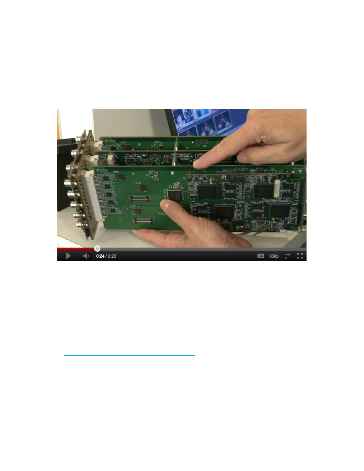
Introductory Video from David Wood, Chief Design Engineer
This product can be configured with various options and in different sizes to address a wide variety of
applications. Please view the two-minute video below for a brief overview presentation of the Avenue
Flexible Matrix Router by Chief Design Engineer, David Wood.
David Wood, Chief Design Engineer, talking about the new Flexible Matrix Router. Note that
the photograph is a link to a video on YouTube.
Additional Resources
In addition to this document, please refer to these resources:
• Introductory video by Cindy Zuelsdorf, Marketing, about the Avenue Flexible Matrix Router
• Avenue Flexible Matrix Router Brochure
• Avenue Flexible Matrix Router Quick Start Guide
• Product page from the Ensemble Designs website
www.ensembledesigns.com Page 14
Page 15

Avenue 9430 Flexible Matrix Router Installation, Configuration and Operations Guide
Chapter 2: System Overview
In this Chapter
This chapter addresses the following topics:
• Hardware Elements
• Applications
• Example Diagram of Complete Router System with All Options Installed
• Router Expansion Example for a 21 In x 9 Out Router Configuration
• Example Diagram of Router System Using One 9430, One 9440 and One 9435
The Avenue Flexible Matrix Router is a digital Router that can be configured in a variety of matrix sizes
and with a variety of options. Highlights of its functionality include ease of expansion, configurable
input/output ports, exclusive video thumbnails, configurable control panels, built-in test signal
generator and sync pulse generator, and assignable resources such as optional clean and quiet
switching on multiple outputs.
The exclusive live thumbnail display in the Router Control Panel and web user interface lets you look at
your source before you perform a take.
Highly flexible matrix sizing lets you decide on your own configuration. The basic size is 8 inputs by
2 outputs. You can add user configurable input/output ports up to 28x2 (or 8x22) and any size in
between.
The assignable clean switch option gives you full frame synchronization that locks to your house
reference so it can switch cleanly between asynchronous sources. VITC captured from the reference
input can drive time-scheduled switching.
The Avenue modular digital video router is a flexible, technologically advanced small router. Its
flexibility makes it possible to tailor the input/output dimensions to a wide range of applications,
including mobile and portable systems, ENG trucks, QC monitoring stations, graphics and postproduction islands, edit suites, ingest, production switcher pre-select, master control bypass switching,
driving on-set monitors, general utility switching, and numerous other applications.
Hardware Elements
The hardware elements that make up the Router are as follows:
• 9430 Router Module
• 9440 I/O Expansion Module
• 9435 Dual Clean Switch Submodule
• 5830 Router Control Panel
www.ensembledesigns.com Page 15
Page 16

Avenue 9430 Flexible Matrix Router Installation, Configuration and Operations Guide
9430 Router Module
The control system for the Router resides on this module. The control system, discussed at length in
Chapter 4: Configuration, is accessed through a web browser interface.
The 9430 Router Module provides eight dedicated Input Ports and two dedicated Output Ports.
In addition to these Inputs and Outputs, the 9430 provides video thumbnail capture, Test Signal
Generation, and Genlock/Timing. The smallest possible version of the Flexible Matrix Router consists
only of a 9430 module.
Built-in Signal Diagnostics
Circuitry on the 9430 module detects and measures key parameters associated with each video
source and makes these parameters available for display on both the hardware and software panels.
Parameters include synchronicity and timing, line and frame rate, embedded audio presence/absence,
closed caption information, and timecode data.
Fail-Safe Relay Bypass Mechanism
Input 1 and Output 1 are linked together by a fail-safe relay bypass mechanism. In the event of a
power or system failure, the signal presented to Input 1 is directly connected to Output 1.
9440 I/O Expansion Module Option
One or two 9440 I/O Expansion modules can be added to a 9430 to provide additional digital I/O
Ports. Each 9440 adds ten bi-directional ports, each of which can be independently configured as an
input or an output. These expansion modules attach to either side of the 9430 core module to form a
maximum set of three boards. A Router with two 9440 modules has a total of 30 ports.
9435 Dual Clean Switch Submodule Option
Each of the 9435 submodules provide two independent frame-synchronized SDI clean switches,
resulting in the ability to switch cleanly between asynchronous sources. Audio sample rate conversion
makes the audio output clean and silent. You can use the control system to assign a clean switch to
any SDI input or output. Each clean switch can be assigned to one or more outputs by using the Follow
port configuration. For more information about port configuration choices, please see Configuring the
Router’s Ports on page 54.
A total of two 9435 submodules, providing a total of four independent clean switches, can be installed.
The first 9435 mounts on the 9430 Router Module. The second 9435 installs on the 9440 Input
Expansion Module in expansion position 1.
5830 Router Control Panel
The Router Control Panel communicates with the 9430 Core module by Ethernet to control the Router
and display thumbnail previews of content. An essentially unlimited number of 5830 Router Control
Panels can be used in a Router system. You can also access signal diagnostic information from the LCD
display on the Router Control Panel. The Router Control Panel is only 1.8” (45mm) deep, so it can be
installed in very shallow positions.
www.ensembledesigns.com Page 16
Page 17

Avenue 9430 Flexible Matrix Router Installation, Configuration and Operations Guide
Long Distance Capability
Because each Router Control Panel connects to the Router over Ethernet, and because Ethernet
reaches much farther than coaxial cable, Router Control Panels can be physically located very far away
from the Router if desired.
For example, if you need the capability to select sources at the transmitter remotely, such as in the
event of either a master control switcher failure or a microwave link failure between the studio and the
transmitter, you can use the Router as part of a backup switcher at the transmitter. Sources such as a
network feed, a small server or a weather camera could be switched to air in an emergency. You can do
the selecting remotely, such as at the studio (or even from home if need be), or from any location with
Ethernet access.
Applications
The flexibility of the Avenue Flexible Matrix Router system makes it possible to tailor the input
and output dimensions to a diverse range of requirements. Therefore, it can accommodate many
environments and applications, including the following:
• Mobile and portable systems
• QC stations
• Graphics and post-production islands
• ENG trucks
• Edit suites
• Ingest
• Production switcher pre-select
• Master control bypass switching
• Driving on-set monitors
• General utility switching
Cuts-Only Master Control
When used in conjunction with the Clean Switch option, and because it performs cuts rather than
fades and wipes, the Flexible Matrix Router can function as a Cuts-Only Master Control Switcher.
Master Control Bypass
Facilities such as TV stations can use the Flexible Matrix Router as a Master Control Bypass switcher.
With the same sets of feeds going to both the Master Control Switcher and the Flexible Matrix
Router, program sources can be switched over to the Flexible Matrix Router during maintenance, for
emergencies, or during upgrades.
The Master Control Switcher and the Flexible Matrix Router can both go through a protection switch,
such as the Avenue 7455 HD/SD/ASI/310M protection switch, before going on to an MPEG encoder for
transmission.
www.ensembledesigns.com Page 17
Page 18

Avenue 9430 Flexible Matrix Router Installation, Configuration and Operations Guide
Quality Control and Signal Monitoring
The Flexible Matrix Router can be used for quality control and signal monitoring. In a smaller TV
station, for example, personnel in engineering can monitor a variety of channels internally. For a larger
facility, someone would be performing dedicated quality control monitoring.
For just a quick check, the small LCD display on the Router Control Panel may provide enough of an
image preview. Or the LCD can be used as a preview before bringing up the signal on a monitor. The
LCD display can also be used to show signal metadata while a monitor can be used to view the picture
in a larger format or perhaps as a quad split.
Monitors and Projectors for Venues
The Flexible Matrix Router brings many sophisticated options to non-broadcast environments, such
as corporate meeting rooms, event venues and churches. Because of the simple and accessible Router
user interface that runs on a web browser, iPad or Router Control Panel, all video professionals can
easily make use of the Router.
For example, a guest speaker who wants to access an assortment of media could have numerous
inputs available to them and a number of destinations, such as projector screens or monitors. Using an
iPad as a router controller, for instance, the guest speaker would only have to tap the iPad a couple of
times to change the source going to a monitor or screen projector. Sources could include still pictures
with background music, lyrics, and live feeds.
Another possible source for such environments is content from the Internet. When a computer with
Internet access is connected to a BrightEye Mitto™ scan converter, for example, you can upconvert
video from YouTube, Skype or any website to SD, HD or 3G SDI video and route that signal to any
Router destination. Mac and PC computers, iPhone and iPad can all be used as sources with BrightEye
Mitto. All Mitto units accept VGA, DVI and HDMI input signals from PC and Mac computers.
www.ensembledesigns.com Page 18
Page 19
Avenue 9430 Flexible Matrix Router Installation, Configuration and Operations Guide
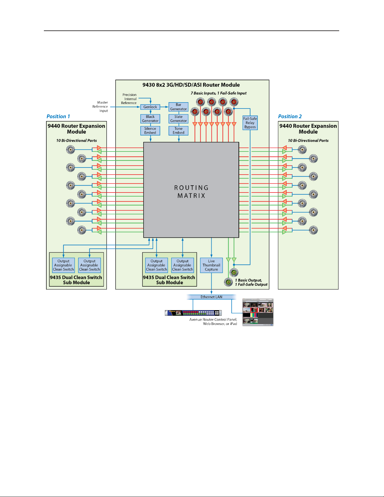
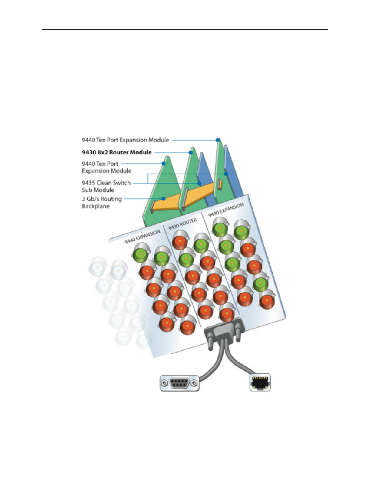
Example Diagram of Complete Router System with All Options Installed
The above diagram illustrates one 9430 Router Module with two 9440 I/O Expansion Modules, two
9435 Dual Clean Switch Submodules, and a Router Control Panel (5830). Such an implementation
would have 30 Ports and four independent assignable Clean Switches. Each 9440 has 10 bi-directional
Ports. This combination of hardware components would be installed in an Avenue 3RU Frame.
www.ensembledesigns.com Page 19
Page 20
Avenue 9430 Flexible Matrix Router Installation, Configuration and Operations Guide
Router Expansion Example for a 21 In x 9 Out Router
Configuration
The 9430 and 9440 modules combine to form a Router with 20 or 30 Ports. They are joined together by
three signal routing backplanes which provide the interconnection between the I/O ports on the 9440
and the 9430 core module.
The Router board sets with 20 and 30 Ports install in an Avenue 3RU Frame. The 10 Port Router,
consisting of a single 9430 module (and optionally including a 9435 Dual Clean Switch), can be
installed in either the Avenue 1RU or 3RU Frames.
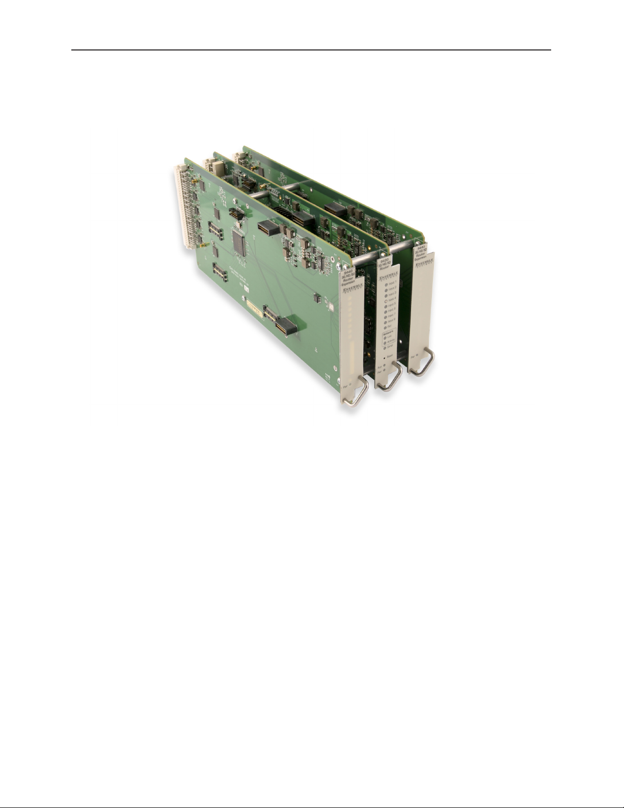
30 Port Router: one 9430 Router Module, two 9440 Expansion Modules, two
9435 Clean Switch Submodules, and Routing Backplanes, viewed from the
rear. Use the RS-232 or Ethernet to connect with Avenue Control Panel, Master
Control, or Automation System.
www.ensembledesigns.com Page 20
Page 21
Avenue 9430 Flexible Matrix Router Installation, Configuration and Operations Guide
!
/
1
2
!
/
1
2
9435
!
/
1
2
9435
!
/
1
2
Clean Switch /!
Frame Sync
Black Gen
embedded!
silence
Bar Gen!
w/ Slate
embedded!
tone
Clean Switch /!
Frame Sync
Genlock
Frame Master
Reference
12 Inputs!
3G/HD/SD SDI
Internally Generated
Anchor Tight
Wx Graphics
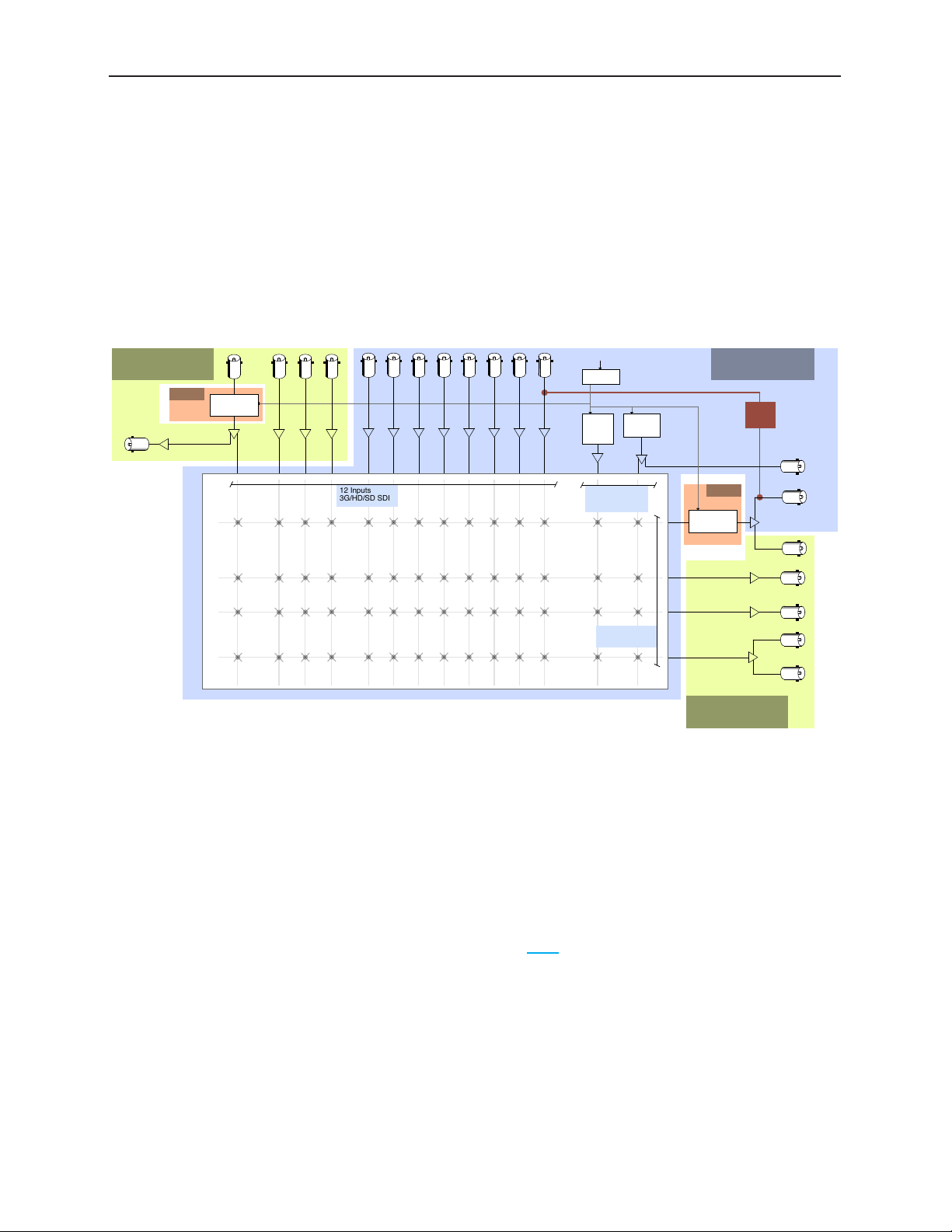
Example Diagram of Router System Using One 9430, One 9440 and One 9435
The Flexible Matrix Router is very versatile. Using the Router’s built-in configuration tools, you can
create highly customized and sophisticated systems. This produces very efficient, compact solutions
to a wide variety of system design challenges. And because the customization is “soft,” the solution can
evolve as needs change—in some cases without moving a single cable.
Server 2
Tower Cam
Studio Wide
Still Store
News 1
MC
8x2 Router Module
Failsafe!
Relay!
Bypass
Color!
Black
Bars
3G/HD/SD SDI
4 Outputs!
News Room Floor Monitors
9440!
Expansion Module
Feed to Transmiiter!
w/ fail-safe
Xmt Feed!
Monitoring
Server Record In
QC Monitor
9440!
Expansion Module
Dedicated!
Network Output
Network
ENG Rx 1
Sat 1
Matrix
Server 1
In this example, a bypass and backup switcher for Master Control uses just one 9430, one 9440, and
one 9435.
9430!
Dedicated!
SDI Black Output
Clean Switches are used to make the Network input synchronous to all outputs and to provide clean
and quiet switching (between all inputs) on the output feeding the transmitter. In the example shown
above, the switching matrix is configured as 12 Sources and 4 Destinations. Output ports using the
Follow feature provide duplicate outputs of selected Destinations, and a loop-through of the
Network input.
A large format version of this diagram is available as a PDF here.
www.ensembledesigns.com Page 21
Page 22

Avenue 9430 Flexible Matrix Router Installation, Configuration and Operations Guide
Chapter 3: Installation
In this Chapter
This chapter consists of two parts:
Part One: Module Assembly, describes how modules are assembled in the event that you need to add
modules or submodules in the future. Original orders are delivered preassembled. Topics addressed
include:
• Original Orders Preassembled
• 9430 Router Module
• 9435 Dual Clean Switch Option
• 9440 I/O Expansion Option
Part Two: Required Cable Connections, describes cable connections that all customers must perform,
as well as Router Control Panel (5830) installation. Topics addressed include:
• Seating the Board Set Firmly in the Frame
• Installing the BNC Plastic Overlays
• Digital Signal Connections
• Router Control Connections
• Connecting a Timing Reference to the Avenue Frame
• Connecting a Timing Reference to the 9430 Router
• Router Control Panel Installation
Detailed instructions for installing the Avenue frame itself are provided in the Avenue System
Overview Manual.
www.ensembledesigns.com Page 22
Page 23
Avenue 9430 Flexible Matrix Router Installation, Configuration and Operations Guide
PART ONE: MODULE ASSEMBLY
Original Orders Preassembled
For original orders, Ensemble Designs will assemble all modules (the 9430, 9435, and 9440 modules
as applicable) before shipping them to your facility. You can then install the assembly into the Avenue
frame as a single unit. However, if you add modules at a later time, these instructions will show you
how to assemble and install them.
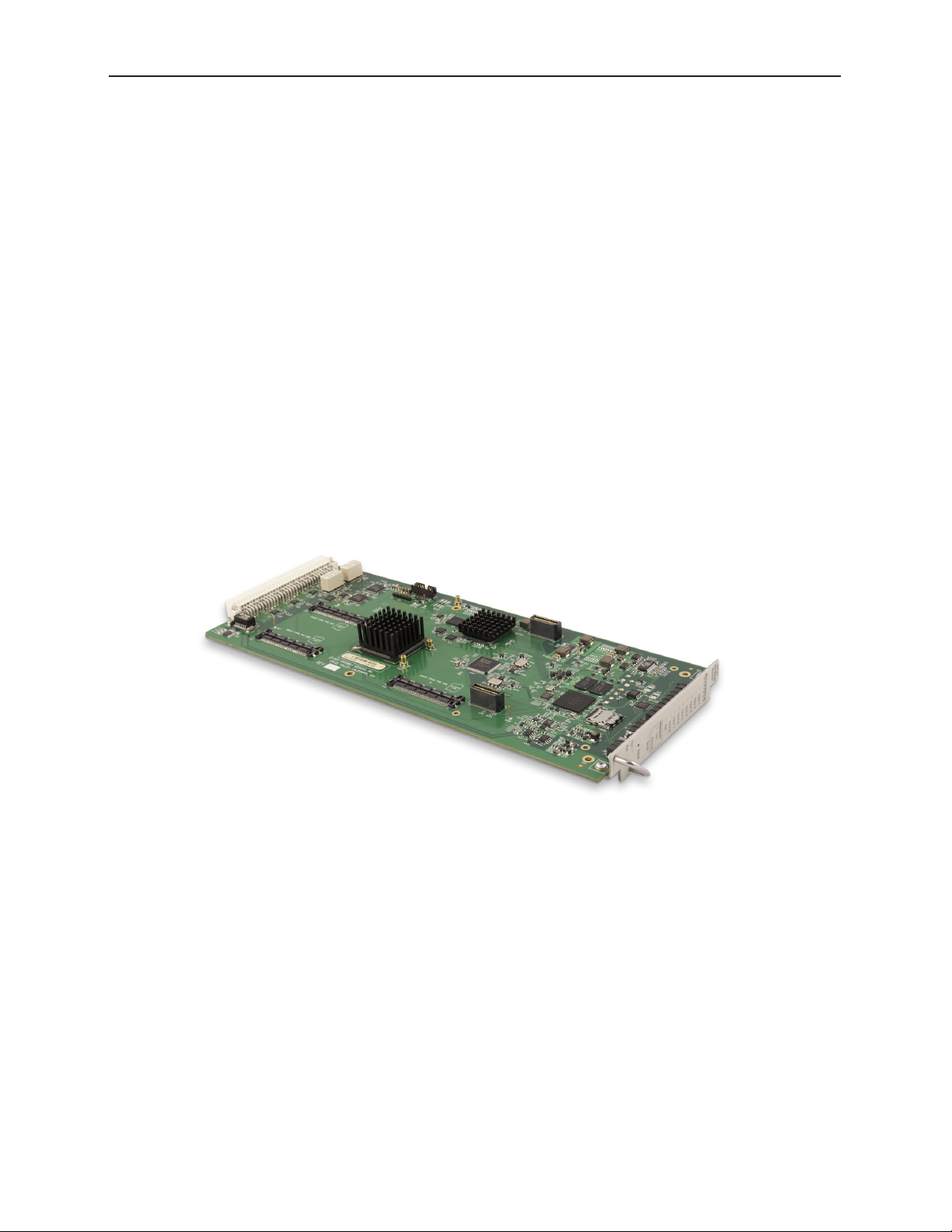
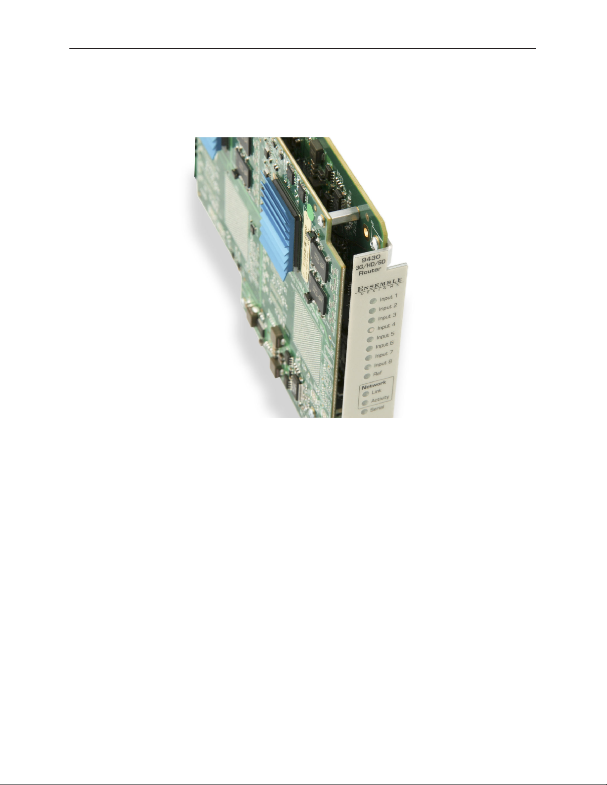
9430 Router Module
Every Router will include a 9430 Router Module—a 10 Port Router with 8 dedicated Inputs and 2
dedicated Outputs. Shown below is a 9430 Router Module with no additional modules installed.
The 9430 Router Module with no additional modules installed
www.ensembledesigns.com Page 23
Page 24
Avenue 9430 Flexible Matrix Router Installation, Configuration and Operations Guide
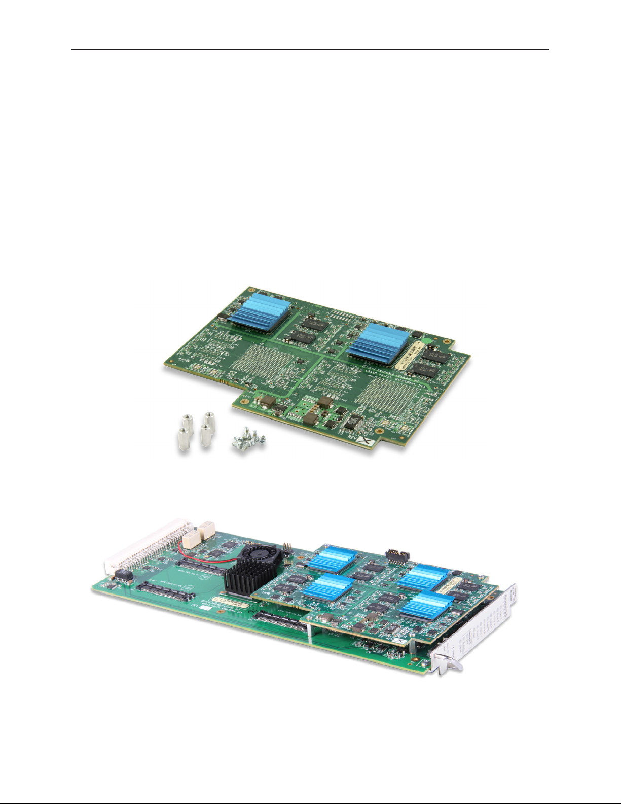
9435 Dual Clean Switch Option
An optional 9435 Dual Clean Switch submodule can be mounted to one or both of the following:
• the 9430 Router Module
• the 9440 Expansion Module in the Expansion 1 position (the left hand position as viewed from
the front of the frame)
The 9435 Dual Clean Swith submodule is secured to the 9430 and/or 9440 by screws and threaded
stand-offs in four positions.
Note: Only a 9440 in the Expansion 1 position supports the 9435 Dual Clean Switch.
Although it is mechanically possible to install a 9435 on a 9440 in Expansion 2, that
9435 will not appear as a resource in the configuration menus.
A 9435 Dual Clean Switch submodule with 4 screws and threaded stand-os
A 9430 Router Module with a 9435 Dual Clean Switch submodule installed
www.ensembledesigns.com Page 24
Page 25
Avenue 9430 Flexible Matrix Router Installation, Configuration and Operations Guide
9430 and 9435 Fit in a Single Frame Slot
Note that the 9435 fits within the slot profile of the 9430, so the combination of the two still occupies
a single frame slot in either a 1RU or 3RU Avenue Frame.
Detail of a 9435 Clean Switch installed on a 9430 Router Module
www.ensembledesigns.com Page 25
Page 26
Avenue 9430 Flexible Matrix Router Installation, Configuration and Operations Guide
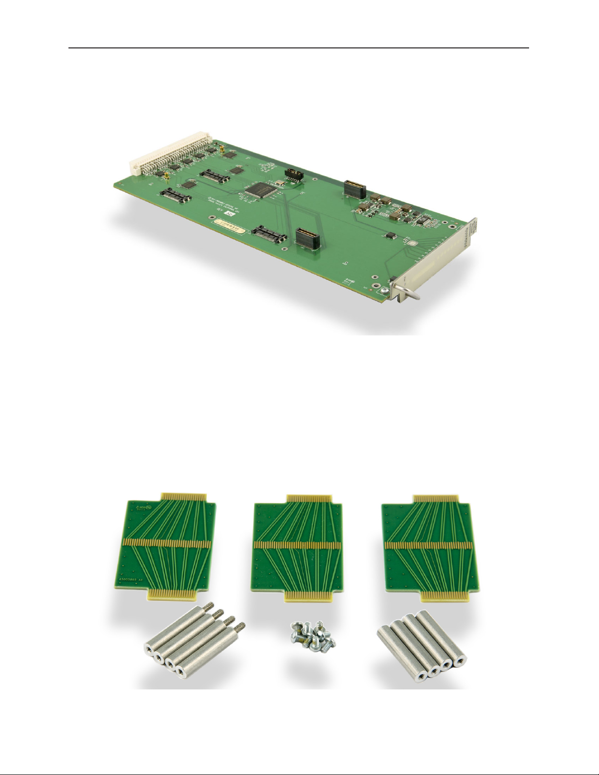
9440 I/O Expansion Option
A maximum of two 9440 I/O Expansion Modules can be attached to the 9430 Router Module, one per
side.
A 9440 I/O Expansion Module
The 9440 I/O Expansion Modules are mechanically attached to a 9430 with screws and stand-offs.
The signal electrical connection is made by three high-speed routing backplanes with precision
transmission lines designed to support signals up to 3 Gb/s.
Two Types of Routing Backplane Kits
There are two types of routing backplanes, one for 20 Port Routers, and one for 30 Port Routers.
Pictured below is the attachment kit for a 30 Port Router.
An attachment kit for a 30 Port Router
www.ensembledesigns.com Page 26
Page 27
Avenue 9430 Flexible Matrix Router Installation, Configuration and Operations Guide
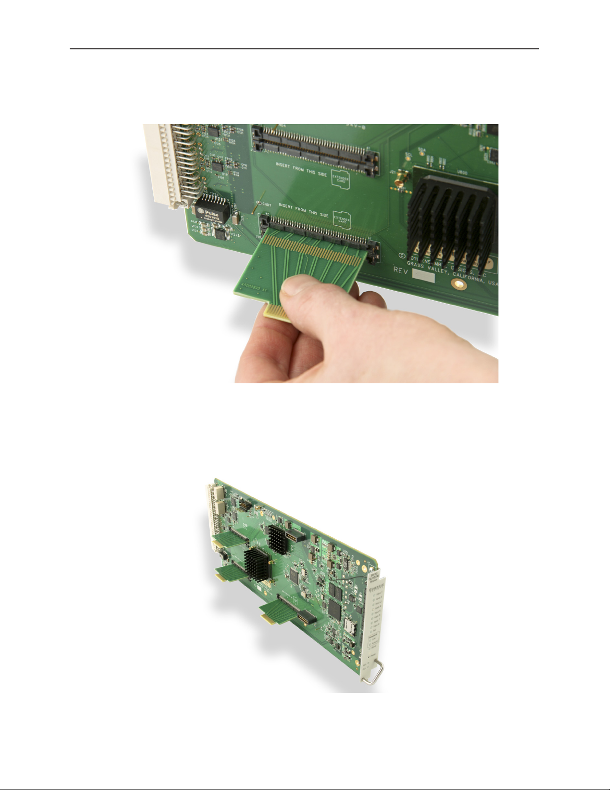
Sliding Routing Backplanes through Slots in the 9430
The routing backplanes slide through slots in the 9430 module, picking up electrical connections on
each side from these slot connectors.
From the top side of the 9430, gently insert the the routing backplanes through the slot connectors.
The slot connectors on the 9440s are set back farther from the module edge connector than on the
9430. Therefore, the routing backplanes must be oriented with the small ends offset away from the
edge connector. Beyond that, the backplanes do not have polarity.
The 9430 ready to accept a 9440 I/O Expansion Module.
www.ensembledesigns.com Page 27
Page 28
Avenue 9430 Flexible Matrix Router Installation, Configuration and Operations Guide
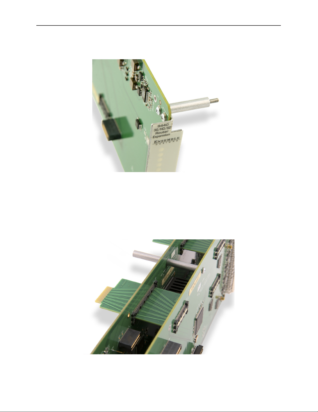
Installing Stand-Offs on the 9440
Install the four stand-offs on each 9440 using one screw per stand-off, as shown below.
Stand-os on the 9440 Expansion Module
Aligning the 9440 with Routing Backplanes
Align the 9440 with the routing backplanes. Gently guide the backplanes into the smaller slot
connectors on the 9440. The narrow end of the backplane will be flush with the connector on the
9440.
Complete the mechanical attachment with screws in the stand-offs.
A completed stand-o with screw in place and backplanes
connected to 9430 and 9440
www.ensembledesigns.com Page 28
Page 29
Avenue 9430 Flexible Matrix Router Installation, Configuration and Operations Guide
Example of Completed Assembly
The example shown below consists of one 9430 and two 9440s, with backplanes and stand-offs in
place, providing 30 ports. This assembly is ready to install in an Avenue 3RU Frame.
An Assembled 30 Port Router ready to install in an Avenue 3RU Frame
PART TWO: REQUIRED CABLE CONNECTIONS
Seating the Board Set Firmly in the Frame
Install the board set in the frame, taking care to insure that the modules are fully seated into the frame
backplane connector. This requires more force than with a single module.
Avenue 3RU Frame Partition Divider Consideration
Because a multi-board assembly cannot span the divider in the Avenue 3RU Frame between slots
4 and 5, the three modules making up a 30 Port Router cannot be installed in either of these two
ranges:
• Slots 3, 4, 5
• Slots 4, 5, 6
It is strongly recommended to take this into account during frame and slot planning. Otherwise, you
may have to make a last-minute change to an otherwise carefully planned installation design. Despite
this restriction, it is still possible to install as many as three 30 Port Routers in a single 3RU frame.
www.ensembledesigns.com Page 29
Page 30
Avenue 9430 Flexible Matrix Router Installation, Configuration and Operations Guide
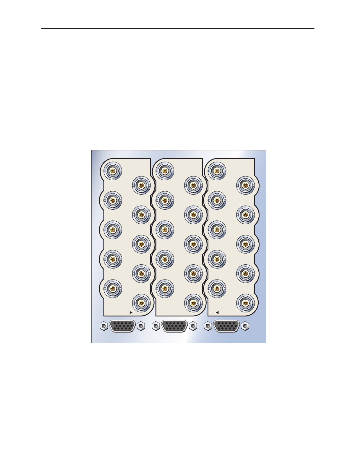
Installing the BNC Plastic Overlays
On the rear of the Avenue frame, install the BNC plastic overlays provided onto the corresponding
group of rear BNC connectors associated with the Router location.
The 9440 modules have two plastic overlays, one for the Expansion 1 position and one for the
Expansion 2 position. As an orientation aid, the bottom of each 9440 plastic overlay is marked with an
arrow that should be pointing toward the 9430 that sits between the 9440s.
Note that the plastic overlays have optional adhesive backings for securing them to the frame. Use
of the adhesive backing is only necessary if you would like the location to be permanent and is not
recommended if you need to change module locations.
9440 Router
Expansion 2
I/O Port 21
I/O Port 22
I/O Port 23
I/O Port 24
I/O Port 25
I/O Port 26
I/O Port 27
I/O Port 28
I/O Port 29
I/O Port 30
9430
9430 Router
Input Port 1
Output Port 2
Output Port 1
(Fail-safe)
Input Port 2
Input Port 3
Input Port 4
Input Port 5
Input Port 6
Input Port 7
Input Port 8
Network/Serial
9440 Router
Expansion 1
I/O Port 11
I/O Port 12
I/O Port 13
I/O Port 14
I/O Port 15
I/O Port 16
I/O Port 17
I/O Port 18
I/O Port 19
I/O Port 20
9430
BNC plastic overlays on the rear of the frame
www.ensembledesigns.com Page 30
Page 31

Avenue 9430 Flexible Matrix Router Installation, Configuration and Operations Guide
Digital Signal Connections
The digital inputs and outputs of the Router are all equally capable of supporting 3G SDI, HD SDI,
SD SDI, DVB-ASI, SMPTE 310M and AES audio signals. Connections to sources and destinations are
made with 75 ohm coaxial cable.
Cable Length Considerations
An important technical consideration in system wiring is the length of the cables that run between
different pieces of equipment. The high frequency content of the serial digital signal, which is
attenuated in proportion to the length of the cable, sets an upper limit to the distance over which
the interface will work reliably. Beyond that distance, data bit errors will corrupt the signal and render
the content unusable. The maximum length for digital grade, RG-6 type cable (such as Belden 1694A)
varies according to the data bit-rate of the interface as follows:
Type Bit-Rate Maximum Cable Length
3G HD SDI 3 Gb/s 70 meters (229 feet)
HD SDI 1.5 Gb/s 100 meters (328 feet)
SD SDI 270 Mb/s 300 meters (984 feet)
DVB-ASI 270 Mb/s 300 meters (984 feet)
SMPTE 310M 19.3 Mb/s 100 meters (328 feet), but 30 meters (98 feet) is recommended
due to the inherent weakness of the 310M signal
AES 3 Mb/s 100 meters
These numbers are conservative in order to provide a margin of safety that accommodates variations
in the output amplitude and jitter content of sources, and the input sensitivity of destinations. Do not
exceed these values because when a system is pushed beyond its design limitations, what works one
day may not work the next day.
Furthermore, these numbers assume a direct, single cable connection between devices. If the signals
are passing through patch panels or cable couplers, the maximum total cable length must be reduced.
Fail-Safe Bypass from Input 1 to Output 1
The fail-safe bypass feature of the Avenue Flexible Matrix Router supports a connection from Input 1
to Output 1 in the event of a system or power failure. This is accomplished in a simple manner: Bypass
connects the two ports (BNC connectors) together through a passive, mechanical relay. This means
that the signal will be carried through the Router even when there is a total loss of power and control.
But it also means that the length of the cable between the source and destination is now the total of
the input and output cabling. That total must be less than the bit-rate appropriate maximum listed
in the above table. And since the Router in bypass mode is effectively a cable coupler, that maximum
needs to be further reduced. If other elements or requirements in a system design render the bypass
behavior irrelevant, this combined cable length consideration can be disregarded.
It is possible to extend performance beyond these maximums by the use of lower loss RG-11 cable
such as Belden 7732LL. The low-loss performance comes from a larger dielectric cross section, so these
alternatives are less flexible and more challenging to install and terminate.
Conversely, smaller diameter cable (Belden 1855A) is often favored for its lower weight and higher
installation density. These choices must take into account their greater high frequency attenuation.
www.ensembledesigns.com Page 31
Page 32

Avenue 9430 Flexible Matrix Router Installation, Configuration and Operations Guide
Router Control Connections
Although the Avenue Frame system is equipped with both RS-232 and Ethernet interfaces, the 9430
has its own dedicated control connections. The communication bandwidth needed to support the live
video thumbnails and the expectation on the part of third-party control systems (automation, event
control) for a dedicated control port require this.
RS-232 and 100Mb Ethernet Interface Adaptor Cable
The connection to both the RS-232 and 100Mb Ethernet interfaces on the 9430 are accomplished
through an adaptor cable (part number 23700040) which connects to the HD-15 connector specific to
the slot where the 9430 is installed. This adaptor is included with the 9430 module. It is configured as a
“Y” cable with a separate leg for the 9-pin D-Sub RS-232 and RJ-45 Ethernet connectors. If only one of
these interfaces is required, it is acceptable (though irreversible) to cut off the unwanted leg.
The Ethernet port should be connected with CAT5 or CAT6 cabling to a network Ethernet router or
switch to make it accessible to computers on the network. This port can also be directly connected to
a computer or to a Router Control Panel (5830). The Ethernet port will auto-sense cable direction, so a
cross-over cable is not needed.
The RS-232 port will operate from 1,200 to 115,200 baud.
The configuration of these interfaces and the selection of serial protocol are described in Chapter 6:
External Control on page 96.
Adaptor “Y” cable (part number 23700040)
for connecting the 9430 to RS-232 and 100Mb
Ethernet interfaces
Rear BNC connectors and the HD-15 connector
on the 9430
www.ensembledesigns.com Page 32
Page 33

Avenue 9430 Flexible Matrix Router Installation, Configuration and Operations Guide
Connecting a Timing Reference to the Avenue Frame
In order to genlock the video resources in the Router (TSGs and Clean Switches) to a larger video
system, connect a timing reference to the Master Reference Input on the Avenue Frame. This is a
loop-through connection on the 3RU Frame which requires a termination. On the 1RU Frame it is an
internally terminated input.
The Router will also use this reference input to determine the vertical interval switching point.
Connecting a Timing Reference to the Master
Reference Input on the rear of the Avenue Frame.
The loop through is terminated with a 75 ohm
terminator.
Connecting a Timing Reference to the 9430 Router
The reference input of the 9430 will accept these reference types:
• NTSC or PAL analog video
• HD Tri-Level Sync
• 10 MHz precision reference
When VITC (Vertical Interval Timecode) is present on NTSC or PAL analog composite reference sources,
it will be available to the Router for event scheduling.
The Router can operate without a timing reference by utilizing its own internal SPG (Sync Pulse
Generator).
See Setting Up Timing and Genlock on page 70 for more details about configuring the Router’s
Timing and Genlock systems.
www.ensembledesigns.com Page 33
Page 34

Avenue 9430 Flexible Matrix Router Installation, Configuration and Operations Guide
Router Control Panel Installation
Connecting Ethernet Cable to RJ-45 Port
Make an Ethernet connection to the RJ-45 port on the rear of the Router Control Panel. The Ethernet
cable should be connected to a network Ethernet router or switch to make it accessible to the Router.
The Ethernet port will auto-sense cable direction, so a cross-over cable is not needed.
A modular power supply is provided to power the Router Control Panel. Alternately, power can be
supplied by the Ethernet connection using PoE (Power over Ethernet), provided that you have a PoEenabled Ethernet switch to insert power into the Ethernet cables.
The rear of the Router Control Panel. Note the three connectors: the RJ-45 Port, the
Power Input, and the 9-Pin GPI Connector.
Long Distance Capability
Because the Router Control Panels connect to the Router over Ethernet, and because Ethernet reaches
much farther than coaxial cable, Router Control Panels can be physically located very far away from
the Router if desired. Therefore, you can install the Router Control Panels wherever you need them to
be located as long as you have Ethernet connectivity.
The Router Control Panel is only 1.8” (45mm) deep, so it can be installed in very shallow positions.
The front of the Router Control Panel. Both rows of buttons are capable of
illuminating either red or green.
www.ensembledesigns.com Page 34
Page 35

Avenue 9430 Flexible Matrix Router Installation, Configuration and Operations Guide
Labeling Buttons
The Router Control Panel comes with two button labeling options:
1. Pre-printed key cap inserts, described on this page, and
2. A customizable label template that generates a PDF, described on the next page.
First Method: Key Cap Inserts
The provided key cap inserts give a broad range of terms and numbers printed on clear plastic sheets.
Each individual button legend pops out from its sheet and can be inserted into the Router Control
Panel buttons between the clear overcap and the white diffuser, if desired.
The button legends are designed to be used individually—one per button, or as a combined set—two
on a button. When combining them, one appears higher on the button and the other appears lower.
To Place a Button Legend Inside a Control Panel Button
1. Pull a button off of the Control Panel by simply squeezing and pulling. Each button is held to the
Panel with a pressure fit. A bit of pressure is required.
2. Remove the inner white diffuser part of the button from the clear overcap with a fingernail or a
sharp edged tool. Note the orientation of each button: there are slightly indented slits located on
the top and bottom of both the clear overcap and white diffuser.
3. Place a button legend between the clear overcap and the white diffuser, keeping both parts
aligned top to bottom and noting orientation. Snap the two button pieces back together.
4. Snap the button back in place on the Control Panel with some slight pressure. The button must be
level to the plane of the Panel before it will snap correctly back into place.
Button legends can be inserted between the clear
overcap and the white diuser of the key cap.
www.ensembledesigns.com Page 35
Page 36

Avenue 9430 Flexible Matrix Router Installation, Configuration and Operations Guide
Second Method: Customizable Label Template
You can create your own customized button labels directly from one of your Profiles. (For more
information about Profiles, see Creating and Editing Profiles on page 59.) The template draws from
the Port names associated with the Profile you choose. This automatically generates a PDF document
of precisely scaled and aligned labels that you can print on paper or acetate.
To Print Labels from a Selected Profile:
1. From a web browser that has access to the Router, click Settings in the upper left corner. The
Settings > General page displays.
2. Select Profiles in the left navigation panel. The Profiles page displays.
3. For the Profile that you want to use as a basis for printing labels, click Edit. The Edit Profile page
displays.
4. In the upper right area of the Edit Profile page, click Print Label. A Labels.cgi page is created and
displays in a new browser tab or window.
www.ensembledesigns.com Page 36
Page 37

Avenue 9430 Flexible Matrix Router Installation, Configuration and Operations Guide
5. Toward the bottom of the generated label page, click the Print icon. If you do not see this toolbar,
move your mouse cursor across the screen. It may not constantly display itself.
6. Cut the printed labels into two strips as shown below. Align and place the labels onto the Router
Control Panel.
www.ensembledesigns.com Page 37
Page 38

Avenue 9430 Flexible Matrix Router Installation, Configuration and Operations Guide
GPI Control
The Router Control Panel is equipped with 8 GPI (General Purpose Interface) inputs. These provide a
simple, wire-per-function interface for applications such as:
• Master Control Fault “Panic” Button
• Monitor Follow in Camera Shading
• Crosspoint selection from relay contact closure
Connection to the GPI Inputs is made through the female 9-pin D-Sub connector on the rear of the
Router Control Panel.
The pinout of this connector is organized as follows:
Pin # Function
1 - 8 GPI Inputs 1 through 8
9 Ground
A GPI function is activated by making a momentary connection between the GPI pin and ground. This
can be done with a switch, a relay, or an open-collector driver. The GPI input is internally pulled high,
the external control must sink 1 mA.
Functions are assigned to the GPIs through the Control Profile that has been assigned to the panel.
For more information about Profiles, see Creating and Editing Profiles on page 59.
www.ensembledesigns.com Page 38
Page 39

Avenue 9430 Flexible Matrix Router Installation, Configuration and Operations Guide
Chapter 4: Configuration
In this Chapter
This chapter covers the following topics:
• The Router’s Network Environment
• Avenue Touch Screen and Avenue PC Controls
• Initially Connecting to the Router
• Assigning the Router a New IP Address and Subnet Mask
• Establishing Initial Control Point and Profile for Administrator Functions
• Configuring the Router’s Ports
• Creating and Editing Profiles
• Establishing Control Points and Access Authentication
• Setting Up Timing and Genlock
• Configuring Internal Test Signal Generators
• Switch Point Identification
• Working with the Clean Switch Option
The Router's Network Environment
The 9430 Router Module and the Router Control Panels (5830) communicate over a 100 Mb Ethernet
LAN (Local Area Network). In this section, we cover the essential factors for configuring the Router in a
typical networking environment. Your own networking environment may differ. While we recommend
certain practices, you must nevertheless configure the network parameters in each of these devices in
accordance with your network.
Avenue Touch Screen and Avenue PC Controls
While the primary method for controlling the Router is through the web browser interface discussed
in Chapter 5: Operations and Step-by-Step Procedures on page 87, the Avenue Touch Screen or
Avenue PC Controls are used for initially assigning the Router and optional Control Panel new IP
Addresses and Subnet Masks as needed.
If you do not use Avenue Touch Screen or Avenue PC Controls, see Method Two: For Customers Not
Using Avenue Touch Screen or Avenue PC on page 42.
www.ensembledesigns.com Page 39
Page 40

Avenue 9430 Flexible Matrix Router Installation, Configuration and Operations Guide
Initially Connecting to the Router
Establishing Network Connectivity between Controlling Computer and 9430
Please review the section Router Control Connections on page 32 if necessary to make sure you
have network connectivity between your controlling computer and the 9430. It is critical that the
controlling computer be networked to the “Y” adaptor cable which connects to the HD-15 connector
specific to the slot in the frame where the 9430 is installed.
Assigning the Router a New IP Address and Subnet Mask
When you initially power up the 9430 as received from the factory, it will take the self-assigned static
IP address of 192.168.1.100. The 9430 needs to be configured for a manually assigned static IP address
and subnet mask that are compatible with your network environment. The next section of this chapter
describes two methods for assigning a new static IP address and subnet mask to the 9430.
1. The first method is for customers who are using either Avenue Touch Screen or Avenue PC to
control the Avenue Frame.
2. The second method is for customers who have neither Avenue Touch Screen nor Avene PC.
These are general instructions. We recommend that you consult your IT staff if you are uncertain about
any of these network configuration settings.
Method One: For Customers Using Avenue Touch Screen or Avenue PC
To Set the IP Address
1. From the Avenue Frame, select the 9430 module from the Touch Screen. The 9430 menus display.
The Touch Screen interface showing the IP address of
the Router as received from the factory.
2. From the IP Adr menu, enter the IP address you want to use that is compatible with your own
network. The simplest method is to touch each number field, using the keypad to enter the new
numbers. For example, you may want to change the IP address to something like the following:
• 10.123.222.100
www.ensembledesigns.com Page 40
Page 41

Avenue 9430 Flexible Matrix Router Installation, Configuration and Operations Guide
Note that when using Avenue PC instead of the Touch Screen interface, after entering numbers into
the number fields, you will need to hit the “enter” or “return” key for the change to register.
A new IP address has been entered, but not yet saved.
To Set the Subnet Mask
The subnet mask must be set in accordance with the size and topology of your network. The default
setting as received from the factory is 255.255.255.0. This is a typical setting for a smaller network. For
a larger network, a typical setting is 255.255.0.0. If in doubt, use the setting for a larger network.
1. From the Subnet menu, modify the settings as needed. Use the arrow buttons to change the
settings, or touch each number field to use the keypad.
2. When finished, press Save. Both the Cancel and Save buttons turn black to indicate that your new
settings have been saved.
It should now be possible to browse to the 9430 from a computer on your network.
The Subnet Touch Screen menu. The black Cancel and
Save buttons indicate that the settings have been
saved.
www.ensembledesigns.com Page 41
Page 42

Avenue 9430 Flexible Matrix Router Installation, Configuration and Operations Guide
Method Two: For Customers Not Using Avenue Touch Screen or Avenue PC
Temporarily Changing IP Address on Controlling Computer
When you initially power up the 9430 as received from the factory, it will take the self-assigned static IP
address of 192.168.1.100.
In order to connect initially with the Router to assign it an IP address that suits your own network, you
must first temporarily change the controlling computer’s IP address so that it is in the same range as
the 9430’s default IP address.
For example, you could use the following settings temporarily on the controlling computer:
• IP address: 192.168.1.10
• Subnet mask: 255.255.255.0.
Consideration
Depending on how your computer network is configured, it may be simpler to use a computer, such
as a laptop, that is outside of the network solely for the purpose of assigning the Router its new IP
address. This may be simpler than temporarily changing the IP address of the controlling computer
that is within your network.
Instructions for Temporarily Changing the IP Address for Mac and Windows XP
For the Mac
1. From the dock, click the System Preferences icon.
The System Preferences window displays.
2. Click the Network icon.
The Network window displays.
3. From the Configure dropdown control, select
Manually.
www.ensembledesigns.com Page 42
Page 43

Avenue 9430 Flexible Matrix Router Installation, Configuration and Operations Guide
4. Enter the IP address and
subnet mask settings
as applicable, then click
Apply.
Example of network conguration settings for temporarily changing
the IP address of a Mac to make the initial connection to the 9430
Router
For Windows XP
1. Select Start > Control Panel.
The Control Panel displays.
2. Double-click the Network Connections icon.
The Network Connections window displays.
www.ensembledesigns.com Page 43
Page 44

Avenue 9430 Flexible Matrix Router Installation, Configuration and Operations Guide
3. Double-click the Local Area
Connection icon. The Local Area
Connection Status window displays.
4. Click the Properties button. The Local
Area Connection Properties window
displays.
www.ensembledesigns.com Page 44
Page 45

Avenue 9430 Flexible Matrix Router Installation, Configuration and Operations Guide
5. Select Internet Protocol (TCP/IP),
then click the Properties button. The
Internet Protocol (TCP/IP) Properties
window displays.
6. Select the radio button for “Use the
following IP address.”
7. Enter the IP address and Subnet
mask information as applicable, then
click OK.
www.ensembledesigns.com Page 45
Page 46

Avenue 9430 Flexible Matrix Router Installation, Configuration and Operations Guide
To Set the IP Address on the 9430 Router
1. At this point, you are ready to connect to the Router from your web browser. Navigate to the URL
http://192.168.1.100. The first time that you browse to the Router’s IP address, a web page displays
with the message “Control Point Needed.”
The message “Control Point Needed” appears only the rst time you browse to
the Router’s assigned IP address.
2. Click Settings in the upper left part of the browser window. The Settings > General window
displays.
The Settings > General window
www.ensembledesigns.com Page 46
Page 47

Avenue 9430 Flexible Matrix Router Installation, Configuration and Operations Guide
3. From the left navigation panel, click Network. The Network window displays.
4. In the Address field, enter the IP address you want to use for the Router; for example,
10.123.222.100. If you know the Gateway and DNS Server information, enter that information.
Entering the IP address you want to use for the Router that suits your own
network environment
5. Click Save Changes, then click Done. You will temporarily lose connection to the Router at this
point because it is now using an IP address that is outside of the range of your computer.
An expected temporary loss of connection as part of the initial conguration process
www.ensembledesigns.com Page 47
Page 48

Avenue 9430 Flexible Matrix Router Installation, Configuration and Operations Guide
Readjusting Controlling Computer’s IP Address to be in Range of Router’s Newly Assigned IP Address
Now that you have set the Router’s IP address away from its factory default in favor of an IP address
suitable for your own network environment, you must change the IP address of the controlling
computer once again so that it is in a compatible range with the Router’s new IP address.
This may be as simple as reverting to a dynamically assigned IP address if the controlling computer
is on a network with a DHCP server compatible with the Router’s new IP address. Or you may want
to assign a static IP address, provided that it is one that allows you to access the 9430 with its newly
assigned IP address.
Example of readjusting the controlling computer’s IP address to be within range of the
Router’s newly assigned IP address.
www.ensembledesigns.com Page 48
Page 49

Avenue 9430 Flexible Matrix Router Installation, Configuration and Operations Guide
Establishing Initial Control Point and Profile for
Administrator Functions
Now that you have set the Router’s IP address and subnet mask in a manner that suits your network
environment, you can start the configuration process. From the controlling computer, connect to the
9430 to establish an initial Control Point for administrator functions.
To Create an Initial Control Point
1. Navigate to the 9430’s new IP address with your browser. The Control Point Needed window
displays.
2. From the Control Point Needed window, enter the name you want to use to refer to the initial
Control Point (for example, “Router Admin”).
3. Click Request. The message “Control Point Disabled” displays.
4. Click System Settings in the upper left part of the browser window. The Settings > General
window displays.
www.ensembledesigns.com Page 49
Page 50

Avenue 9430 Flexible Matrix Router Installation, Configuration and Operations Guide
5. From the left navigation panel, click Network. The Network page displays.
6. Set the Gateway and DNS Server parameters according to your network configuration. In general,
these settings will be required only in installations with extended networking requirements, such
as a remote site connected by VPN.
7. From the left navigation panel, click Control Points. The Control Points window displays. The
Control Point you just requested is listed under Pending Authorization.
The Settings > Control Points window
www.ensembledesigns.com Page 50
Page 51

Avenue 9430 Flexible Matrix Router Installation, Configuration and Operations Guide
To Assign the Factory Default Profile to the Router Admin Control Point
You must assign a Profile that defines which sources and destinations this Control Point can access. To
begin with, choose the Factory Default Profile. It provides access to the eight Inputs, two Test Signal
Generators, and two Outputs of the basic 9430 module.
1. Under Pending Authorization, select FactoryDefault from the Profile drop-down control.
2. Click Authorize. The Router Admin Control Point now displays in the list of authorized Control
Points.
3. Click Save Changes in the upper left area of the window.
4. Click Done.
You should now be presented with a Router Control view with thumbnail icons, as shown below.
www.ensembledesigns.com Page 51
Page 52

Avenue 9430 Flexible Matrix Router Installation, Configuration and Operations Guide
Now that you have set the Router’s IP address, assigned a Profile and authorized an initial Control
Point, you have access to all of the Router’s configuration settings.
In the example just discussed, the Router Admin Control Point is specific to the controlling computer.
Later sections of this chapter discuss how to create additional Control Points for other computers,
laptops, iPads, and Router Control Panels (5830). You can also use external control panels using serial
protocols.
For more details, see:
• Creating and Editing Profiles on page 59
• Establishing Control Points and Access Authentication on page 63
• Chapter 6: External Control on page 96
www.ensembledesigns.com Page 52
Page 53

Avenue 9430 Flexible Matrix Router Installation, Configuration and Operations Guide
Security and Administrative Access to Settings
All of the Router’s configuration parameters can be accessed through the Settings button in the
upper left corner of the web interface. Without enabling a password, anyone with access to the Router
(meaning anyone who has an authorized Control Point with an assigned Profile) can make changes to
its Settings.
Depending on the security needs of your facility, you may wish to limit access to the Router’s Settings
to only certain people. From the General > Settings page, you can limit administrative access to the
Router by creating a password.
To Limit Access to the Router’s Settings
1. From the Router’s web interface, click Settings. The Settings > General page displays.
2. In the Security section, click the Required checkbox to enable the password functionality.
3. Select a password and enter it into the New Admin Password field. Enter it a second time in the
Repeat New Password field.
4. Click Save Changes, then click Done. The main Router web interface displays.
When a password is required for administrative access, users who try
to access Settings will get a message that says “Password Required.”
Next, we will go over the background information necessary to understand how to configure the
Router’s Ports according to your facility’s intended use.
www.ensembledesigns.com Page 53
Page 54

Avenue 9430 Flexible Matrix Router Installation, Configuration and Operations Guide
Configuring the Router's Ports
Planning Router Port Configuration
Typically, during the planning stage of your Router implementation, you would determine in advance
how you want to initially use the router in terms of inputs, outputs, test signals and clean switches.
Cabling Router to Match Plan
Based on your plan, connect cables to the ports to match your intended use. After you have
completed cabling the router, you will then configure the ports to match how you have wired the
router for your facility.
Before going step-by-step through the process of configuring the Router’s ports, it is necessary to go
over some background information in order to understand what the configuration options mean.
Components Chosen Determines Quantity and Types of Ports Available
The number and types of ports available in the Router is determined by the components chosen.
Without taking the 9435 Clean Switch option into account yet, there are three underlying hardware
module configuration options, creating a total of 33 possible Router sizes:
One 9430 Module
One 9430 module has 8 fixed
inputs and 2 fixed outputs for a
total of 10 ports.
8 x 2 18 x 2
One 9430 Module and One 9440 Module
One 9430 module plus one
9440 module has 8 fixed inputs,
2 fixed outputs, and 10 bidirectional ports for a total of
20 ports.
17 x 3
16 x 4
15 x 5
14 x 6
13 x 7
12 x 8
11 x 9
10 x 10
9 x 11
8 x 12
One 9430 Module and Two 9440 Modules
One 9430 module plus two
9440 modules has 8 fixed
inputs, 2 fixed outputs, and
20 bi-directional ports for a total
of 30 ports.
28 x 2
27 x 3
26 x 4
25 x 5
24 x 6
23 x 7
22 x 8
21 x 9
20 x 10
19 x 11
18 x 12
17 x 13
16 x 14
15 x 15
14 x 16
13 x 17
12 x 18
11 x 19
10 x 20
9 x 21
8 x 22
www.ensembledesigns.com Page 54
Page 55

Avenue 9430 Flexible Matrix Router Installation, Configuration and Operations Guide
Definitions of Port Configuration Choices
Port configuration choices are described below, followed by detailed examples.
Unassigned
For all Port Types
A port can be set to Unassigned when it is not in use. This will remove it from the list of Sources and
Destinations that can be assigned to a Control Profile.
Source
For Fixed Input and Bi-directional Ports
When configured as a Source, a port is an input to the switching matrix. The Source can be given
a name, and under that name it will be available for assignment in a Control Profile. Making this
selection on bi-directional ports will cause them to operate as inputs.
Destination
For Fixed Output and Bi-directional Ports
Configuring a port as a Destination makes it available for use in Control Profiles under its assigned
name as a Router output. A bi-directional port configured as a Destination will cause it to operate as
an output.
Follow
For Fixed Output and Bi-directional Ports
Output capable ports can be configured to Follow, or duplicate, the signal on any Source or
Destination. The Follow configuration essentially makes a port into a DA. Ports that are configured to
Follow will not appear on the list of Sources and Destinations that can be assigned to a Control Profile.
Paired
For all Port Types
This is used to create pairs of Inputs or Outputs to support signals such as Key & Fill, RGB444 Link A & B,
or 3D Left & Right. Pairing associates the port to an existing Source or Destination assignment.
Note: While the Paired configuration is valid on all port types, only input capable ports can
be paired to a Source, and only output capable ports can be paired to a Destination.
Primary TSG
For Fixed Output and Bi-directional Ports
This Primary TSG configuration delivers the test signal being generated in the Primary TSG to an
output port, independently of any user control of the switching matrix.
www.ensembledesigns.com Page 55
Page 56

Avenue 9430 Flexible Matrix Router Installation, Configuration and Operations Guide
Secondary TSG
For Fixed Output and Bi-directional Ports
The Secondary TSG configuration delivers the test signal being generated in the Secondary TSG to an
output port, independently of any user control of the switching matrix.
Note: As described above, only ports that are configured as Sources or Destinations are
available to assign to the Source and Destination buttons on a control panel.
Port Configuration Choices Available According to Port Type
These three port types (fixed input, fixed output, bi-directional) can accept 3G, HD, SD, ASI, 310M, and
AES, and can be configured in the following ways:
For Fixed Input
Fixed Input ports can be configured in one of three ways:
1. Unassigned
2. Source (the default on a new installation)
3. Paired
For Fixed Output
Fixed Output ports can be configured in one of six ways:
1. Unassigned
2. Destination (the default on a new installation)
3. Follow
4. Paired
5. Primary TSG
6. Secondary TSG
For Bi-Directional
Bi-directional ports can be configured in one of seven ways:
1. Unassigned (default on new installation)
2. Source
3. Destination
4. Follow
5. Paired
6. Primary TSG
7. Secondary TSG
www.ensembledesigns.com Page 56
Page 57

Avenue 9430 Flexible Matrix Router Installation, Configuration and Operations Guide
Implementing Router Port Configuration Plan
Now that we have covered the background context for numbers and types of Router ports available
and what the various configuration selections mean, you are ready to configure the Router’s ports.
To Configure the Router’s Ports
From the left navigation panel, select Ports. The Ports page displays. Initially, all the ports show
“Unassigned” for the Type drop-down control.
Conguring Ports: Making a selection from the Type drop-down control for
Output Port 1
www.ensembledesigns.com Page 57
Page 58

Avenue 9430 Flexible Matrix Router Installation, Configuration and Operations Guide
On the Ports page, take the following steps for each port that you plan to use:
1. Select its Type from the Type drop-down control.
2. Indicate a Name (this is the Port’s name that is visible when creating Profiles).
3. If applicable, make a selection from the Follow/Pair drop-down control.
4. Click Save Changes near the upper left area of the browser window to save your changes, or click
Abandon Changes if you want to cancel your changes.
Now that you have configured the Router’s Ports, the next stage of Router configuration is to create
Profiles and Control Points to accommodate as many users as you need in your facility.
An Example Port Conguration
www.ensembledesigns.com Page 58
Page 59

Avenue 9430 Flexible Matrix Router Installation, Configuration and Operations Guide
Creating and Editing Profiles
A Profile provides each Control Point with a configured view of the Sources and Destinations on the
Router. A Profile defines which Sources and Destinations can be accessed from any given Control
Point.
A Profile also defines the order in which Sources and Destinations display for a Control Point. This
ordering feature is of particular interest in the case of RS-232 and TCP/IP control for automation
because it provides a simple means to map Sources and Destinations to suit the automation protocol.
Every Control Point, such as a Router Control Panel (5830), a web browser, an iPad, or a serial interface
for external control, must have a Profile assigned to it in order for that Control Point to be able to use
the Router. Multiple Control Points can share the same Profile.
Each Profile can be customized to have access to unique combinations of not only Destinations, but
also Sources.
Characteristics of Profiles
• Required for every Control Point
• Show only Sources and Destinations
• Define which Sources and Destinations can be accessed
• Define the order in which Sources and Destinations are displayed
• Can be assigned to multiple Control Points
Creating an Initial Set of Profiles
Complete the process of creating as many profiles as your Router users will require. While you can
always create additional Profiles or edit existing ones, you may want to systematically think through
your users’ needs to determine what the initial set of Profiles will be. This will simplify the overall
configuration process as you begin assigning Profiles to Control Points.
To Create a Profile
1. From the left navigation panel, click Profiles. The Profiles page displays.
2. Enter a profile name in the New Profile field.
3. Click Create. The new Profile is listed on the Profiles page.
4. Next to the newly created Profile, click Edit. The Edit Profile page displays. At the outset of creating
a new profile, all the available Sources and Destinations are presented.
5. Click and drag unassigned Sources and Destinations up to the assigned area as needed for this
specific profile. Note that you can rearrange the order as desired. Additionally, you can include
empty spaces to create groupings of Sources and Destinations by clicking and dragging a Space
icon up to be a source or destination.
6. When finished, click Save Changes in the upper left part of the screen, then click Done.
This newly created Profile is now available to assign to one or more Control Points.
Repeat steps 1 through 6 until you have as many Profiles as you need.
www.ensembledesigns.com Page 59
Page 60

Avenue 9430 Flexible Matrix Router Installation, Configuration and Operations Guide
Examples of Profiles
After the functions of the Ports have been defined, the available Sources and Destinations are
selectively assigned to Profiles.
Ports that are configured as Follow, Paired, or Unassigned are not available to a Profile since they
cannot be “controlled.”
Master Control Room (MCR) 10 x 3
In the example below, there are ten Sources and three Destinations for a Master Control Room Profile
named “MCR.” In this example, all available Sources and Destinations have been assigned.
An example of a Master Control Room (MCR) Prole with 10 Sources and
3 Destinations
www.ensembledesigns.com Page 60
Page 61

Avenue 9430 Flexible Matrix Router Installation, Configuration and Operations Guide
MCR Profile Edited and Reordered to 8 x 3
This Profile has been edited to remove access to two of the Sources (ENG Rx 1 and News 1). In addition,
blank spaces have been inserted to organize the selections as they are presented on a control panel.
Those “blanks” will produce unused buttons on the panel.
This profile also has the Sources and Destinations in a different order and will be reflected in
the button assignment on a control panel. If this profile were assigned to the serial interface for
automation control, the order and spacing of Sources and Destinations would “map” the external
control to the Router.
An edited and reordered Master Control Room (MCR) Prole with 8 Sources and
3 Destinations
www.ensembledesigns.com Page 61
Page 62

Avenue 9430 Flexible Matrix Router Installation, Configuration and Operations Guide
MCR Profile Edited to 8 x 1
This Profile has been further edited by removing two Destinations. The result is a Profile that allows
control over only a single output. If assigned to a Router Control Panel (5830), this would effectively
create a single destination panel.
An edited Master Control Room (MCR) Prole with 8 Sources and 1 Destination
www.ensembledesigns.com Page 62
Page 63

Avenue 9430 Flexible Matrix Router Installation, Configuration and Operations Guide
Establishing Control Points and Access Authentication
There are many ways to control the Router and many possible Control Points. In order to manage
these and selectively limit access, each possible Control Point must be authenticated.
An administrator grants access to Control Points through configuring the Control Points page. Access
the Control Points page by selecting Control Points from the left navigation panel of the web
interface. The administrator assigns a previously created Profile to each of the various Control Points.
Control Points can be either assigned or requested. These methods are discussed in more detail
shortly.
Characteristics of Control Points
For each Control Point, only the Sources and Destinations that have been defined by its assigned
Profile will be available.
For a Control Point to work, it must meet these conditions:
• It must be authenticated, meaning that the Enabled check box is selected in the Control Points
window.
• It must have a Profile assigned to it.
If these conditions are not met, the browser window displays the message, “Control Point Disabled.”
The Control Points window showing three Control Points. Note that these Control
Points are enabled (the Enabled check box is selected) and have Proles assigned to
them.
www.ensembledesigns.com Page 63
Page 64

Avenue 9430 Flexible Matrix Router Installation, Configuration and Operations Guide
Examples of Control Points
• 5830 Router Control Panel
• Laptops, iPads and other computers using a web browser
• External control using serial protocols
Configuring the 5830 Router Control Panel
Configuring the Router Control Panel involves:
• Connecting it to the network with an Ethernet cable,
• Turning on the power, (unless it is being powered using Power over Ethernet, or PoE),
• Determining whether to use a static (the default) or dynamic IP address,
• Granting it access to the Router, and
• Assigning it a Profile.
Note: Please connect the Router Control Panel to the network before turning on its power.
The Router Control Panel can be powered using PoE (if you have a PoE switch
upstream from the Panel), or it can be powered by the power supply included with
each Panel.
Assigning an IP Address to the 1RU Control Panel
The 5830 1RU Control Panel comes from the factory with the following defaults:
• Static IP Address: 192.168.1.101
• Subnet: 255.255.255.0
You can change this configuration by accessing the 5830 from a web browser. To do this, you will need
a computer whose network configuration is compatible with the 5830 defaults. In general, this will
require that the computer be connected to the same Ethernet switch as the 5830. A WiFi connection
will work only if it provides access to the 5830 subnet. The computer will need an address in the range
of 192.168.1.0 to 192.168.1.254 in order to connect to the 5830.
Once you can browse to the 5830, you will see the following Settings > General window:
www.ensembledesigns.com Page 64
Page 65

Avenue 9430 Flexible Matrix Router Installation, Configuration and Operations Guide
The 5830 Settings > General window
1. From the left navigation panel, select Network. The Settings > Network window displays.
The 5830 Settings > Network window showing the factory default settings
www.ensembledesigns.com Page 65
Page 66

Avenue 9430 Flexible Matrix Router Installation, Configuration and Operations Guide
Although the 9430 Router Module must use a fixed (static) IP Address, it is possible to operate
the 5830 with either a static address or one that is automatically assigned by your network under
DHCP. If DHCP is selected from the Address Mode pull-down control, the 5830 will obtain an
address from the DHCP server on your network.
Our recommendation is to use a fixed (static) IP Address for the 5830 Control Panel.
2. Configure the fields in the Network settings window appropriately to your network. Gateway and
DNS Server fields are optional.
3. Be sure to double-check the IP Address and Subnet Mask before clicking Save Changes. At this
point, the browser connection will be lost. If you are using DHCP, you can determine what address
was generated by looking at the display on the 5830 itself.
4. Restore the controlling computer’s IP address to its previous settings in order to restore its network
connectivity. You will now be able to reconnect to the 5830 Control Panel’s Settings as needed by
navigating to its new IP Address.
The 5830 Settings > Network window showing modied settings
www.ensembledesigns.com Page 66
Page 67

Avenue 9430 Flexible Matrix Router Installation, Configuration and Operations Guide
Creating a Control Point for the 5830 Panel
1. Browse to the 9430 Settings > Control Points page.
2. Under the heading Add Control Point, enter a name for the 5830 Panel in the Name field.
3. Select FactoryDefault from the Profile drop-down control.
4. Enter the IP address of the 5830 into the Address field.
5. Click Add.
6. Click Done.
At this point, now that you have assigned a compatible IP address to the Control Panel and you have
added it as a Control Point, it will be able to connect to the Router.
The 9430 Settings > Control Points window showing the process of adding the 5830 Control
Panel as a Control Point
www.ensembledesigns.com Page 67
Page 68

Avenue 9430 Flexible Matrix Router Installation, Configuration and Operations Guide
Configuring Other Control Points
For control points other than Router Control Panels, such as iPads and web browsers, there are two
methods for adding them. One method is to request access from a Control Point. The other method is
to assign an IP address to a Control Point. These two methods are described as follows:
First Method: Requesting Access from a Control Point
1. From the desired control point, whether from an iPad or from a computer web browser, enter the
Router's IP address (for example, http://10.123.222.240) into the browser's address field. A browser
window displays indicating that a Control Point is Needed.
2. Enter your desired Control Point name in the Control Point Name field, then click Request. The
browser window indicates that your Control Point has been disabled. Your request has become a
Pending Authorization item for the administrator.
Second Method: Assigning an IP Address as a Control Point
To assign the IP address of a device to create a Control Point:
1. Navigate to the IP address of the Router.
2. In the upper left area, click Settings. The Settings page displays.
3. From the left navigation panel, click Control Points. The Control Points page displays.
4. Under the heading Add Control Points, indicate a name in the Name field.
5. Select a profile from the Profile drop-down control.
6. Enter the IP address for the device into the Address field.
7. Click Add. The Control Points page refreshes to show that the newly assigned Control Point is
enabled.
Approving Pending Authorizations
To approve an authorization request:
1. Click Settings in the upper left area of the browser.
2. Click Control Points in the left navigation panel. The Control Points page displays.
3. Under Pending Authorizations, you will see the request that was just submitted.
4. For this new request, select a Profile from the drop-down control.
5. Click Authorize. The Control Points page refreshes and now includes the newly requested Control
Point.
Note: In order to access Settings, you must have administrator access. See Security and
Administrative Access to Settings on page 53 for more details.
www.ensembledesigns.com Page 68
Page 69

Avenue 9430 Flexible Matrix Router Installation, Configuration and Operations Guide
Number of Control Points That Can Operate Simultaneously
The Router performs best with a maximum of four control points operating simultaneously. The
Router’s data bandwidth is shared across all of the control points. Each additional control point adds
an incremental load on the system. When more than four control points are being used, the Router’s
video thumbnail display performance may begin to degrade.
Asymmetrical Bandwidth Requirements
The continuous delivery of video thumbnails to each control point requires more bandwidth than
is required for performing takes. The video thumbnails, comprising the vast bulk of the data, flow
outward from the 9430 to each control point. The return data, in contrast, consists primarily of
crosspoint commands, or takes. Because the Router has greater bandwidth for takes, the execution of
takes will still be quite responsive even in a large system with markedly degraded thumbnail refresh
performance.
Best Practice: Closing Web Browser Control Points When Not In Use
To minimize the load on the Router, it is recommended to close any Web Browser Control Points that
are not being used.
www.ensembledesigns.com Page 69
Page 70

Avenue 9430 Flexible Matrix Router Installation, Configuration and Operations Guide
Setting Up Timing and Genlock
The 9430 can be locked to a Frame Reference (through the Avenue Frame Master Reference input), or
operated from an internal precision reference. The Reference Source control selects between those
two choices.
The Reference Status indicator displays the status of the currently selected reference.
The Router uses the video format selection of the Primary Test Signal Generator to determine two
system-wide parameters—System Frame Rate, and Vertical Interval Switch Point.
System Frame Rate
Distributed within the Router is a System Frame Rate Reference. It is used to vertically lock the outputs
of the internal Test Signal Generators and the Clean Switch frame syncs. The System Frame Rate is
selected by the Primary Test Signal Generator. If the selected genlock reference is in the same frame
rate family (see the Note on Frame Rates on the next page), the System Frame Rate Reference will also
be locked to the external reference. If the external reference is in a conflicting frame rate family (for
example, SD 525 reference vs. 1080p/50 in the Primary Test Signal Generator), the System Frame Rate
Reference will be internally generated.
Vertical Interval Switch Point
The precise point in the vertical interval where the crosspoint switch will occur is taken from the
timing of the Primary Test Signal Generator. This provides flexibility in the system by allowing, for
example, the use of an SD reference with a matrix that changes at HD switch points.
www.ensembledesigns.com Page 70
Page 71

Avenue 9430 Flexible Matrix Router Installation, Configuration and Operations Guide
Note on Frame Rates
Despite the large number of video formats supported by the Router, there are only three possible
frame rate families.
50 Hz
59.94 Hz
60 Hz
The vast majority of applications, even those including both SD and HD formats, will all fall within a
single frame rate family. For example, as members of the 59.94 family, both SD 525 and 1080i/59.94
can be simultaneously vertically locked to a single reference.
The 50 Hz frame rate family includes 25 Hz and 50 Hz frame and field rates.
This family includes all of the “PAL” related standards in both standard and
high definition.
All of the NTSC-derived standards, including 23.98, 29.97, and 59.94 Hz
field and frame rates. There is a 4 Frame to 5 Frame relationship between
23.98 and 59.94 which allows these to peacefully co-exist.
The “not quite 60 Hz” challenges of the 59.94 world are addressed with this
family which includes 24 Hz, 30 Hz, and 60 Hz field and frame rates. Though
not used for broadcast, this family is useful for film rate and scientific/
industrial applications.
www.ensembledesigns.com Page 71
Page 72

Avenue 9430 Flexible Matrix Router Installation, Configuration and Operations Guide
Configuring Internal Test Signal Generators
The 9430 is equipped with two independent internal Test Signal Generators (TSG). These generators
are driven from the genlock source chosen by the Reference Source control on the Timing and Genlock
page.
Each TSG can be independently configured for format, frame rate, and test pattern. The TSG outputs
will always be clock-locked to the reference source. Further, they will be vertically locked and timed if
the video standard the TSG is configured for is compatible with the provided reference.
Internal
Precision
Master
Reference
Input
Reference
Genlock
Test Sig
Gen 1
Slate/
Cyclops
Tone
Gen
Because the Router generates the test signals internally, the TSGs are available as sources in the Router
(without consuming a physical input BNC) and can be selected to any output destination. Source
names can be assigned to them in the Port Configuration menu, and their position on control panels is
assigned in the Profiles menu.
Audio
Embed
Test Sig
Gen 2
Slate/
Cyclops
Audio
Embed
Test Signal Generator Configuration
There are two sets of configuration controls, one for each TSG. These configurations are independent,
allowing the two generators to operate in different formats – and even at different frame rates. To
configure them to the same standard, and to set them to matching timing (relative to the genlock
reference), make the same settings for Standard, Vertical Timing, and Horizontal Timing.
www.ensembledesigns.com Page 72
Page 73
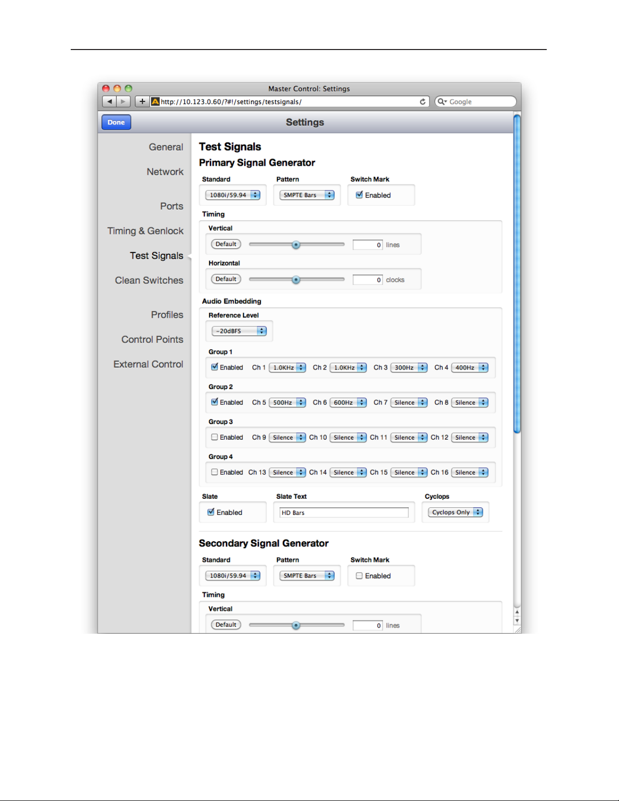
Avenue 9430 Flexible Matrix Router Installation, Configuration and Operations Guide
The Test Signals conguration page
www.ensembledesigns.com Page 73
Page 74
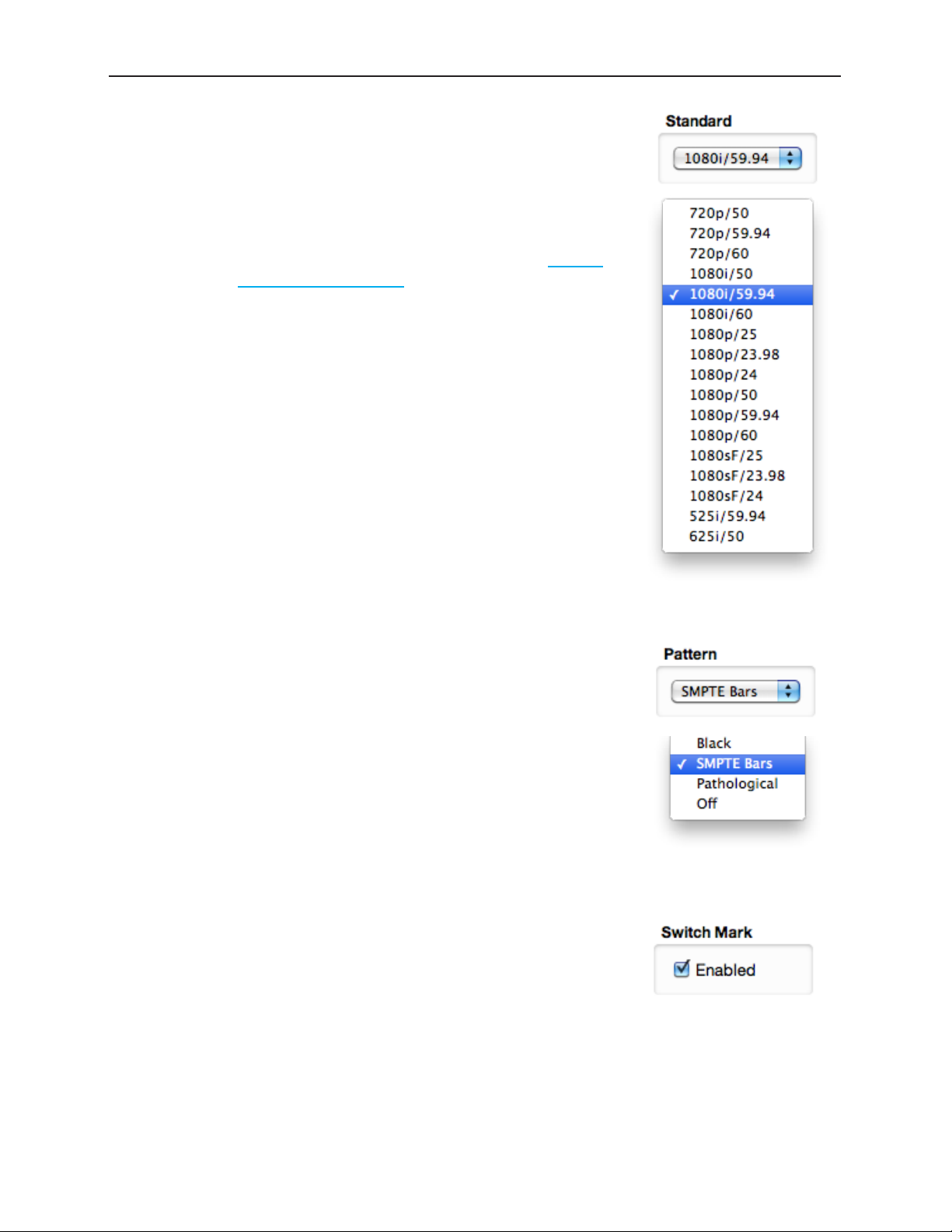
Avenue 9430 Flexible Matrix Router Installation, Configuration and Operations Guide
The configuration controls for the TSGs as are follows:
Standard
Select the desired operating format and frame rate.
Note: The choice of Standard for the Primary Test Signal
Generator sets the System Frame Rate for the entire
Router. This is detailed earlier in the section Setting
Up Timing and Genlock on page 70.
If the Secondary TSG is set to a Standard which is incompatible with
the System Frame Rate (determined by the Primary TSG), then it will
have a free-running H and V. This makes it possible, for example, to
produce both HD1080i/59.94 in the Primary TSG, and 1080i/50 in the
Secondary TSG. Both will have the same frequency accuracy (from the
genlock reference), but only one will be vertically and horizontally
timeable.
Pattern
Choose the desired test pattern to be presented by the TSG.
In addition to Black and Bars, the Pathological test pattern is provided.
Also known as Digital Checkfield, it is a “worst-case” signal that stresses
SDI cable drivers and equalizers. It is extremely useful in proving the
integrity of a system.
Switch Mark
This control enables the Switch Mark feature to identify the point in
the vertical interval where the matrix crosspoint switch will occur. See
“Switch Point Identification” on page 78 for more details.
Note: The Switch Mark is always valid on the Primary Test
Signal Generator because its format and timing
configuration drives the entire Router. It is only valid on
the Secondary TSG when it is configured to match the
Primary.
www.ensembledesigns.com Page 74
Page 75

Avenue 9430 Flexible Matrix Router Installation, Configuration and Operations Guide
Vertical and Horizontal Timing
The Vertical and Horizontal Timing controls adjust the timing of the TSG relative to the genlock
reference. Setting the H and V parameters to 0 will “zero” time the TSG to the reference. Negative
values will cause the TSG to be early with respect to the reference; positive values will make the TSG
later in time.
When the Router is being operated from an external 10 MHz reference, or when it is configured to use
its internal precision frequency reference, there is no external video reference against which H and V
timing can be adjusted. In that case, all of the resources in the router (the TSGs and the Clean Switch/
Synchronizers) will be adjusted against a common, internally generated video timing reference. This
means that they can be adjusted relative to each other. If all of their H and V Timing parameters are
set to identical values (like 0), they will all be locked (synchronous) to each other and they will all be in
vertical and horizontal alignment with each other.
Note: The timing adjustments for the Primary Test Signal Generator are also used to
position the vertical interval switching point in the Router’s matrix. The timing of the
Primary TSG can be compared to other sources on a Waveform Monitor to ensure
that the switch point will be properly aligned to the sources feeding the Router.
Audio Embedding
Each TSG has an Audio Embedder (Multiplexer) that can embed 16 channels of audio into the TSG SDI
output. Audio is embedded in groups, each of which contains 4 channels. There are 9 audio sources for
each channel – 8 tone generators, plus silence.
Note: In the world of digital audio, there is a big difference between “Silence” and “no
signal present.” In the same way that Black is a legitimate video signal, digital silence
must be sent to destinations rather than just sending “nothing.” Thus, TSGs should
generally be configured to embed ALL of the groups that may be in use in a facility,
with Silence chosen as the audio signal for channels where no content is needed
or desired. Otherwise, switching between a TSG with only one group enabled, and
a source with two groups of embedded audio present, will produce undesirable
effects in downstream equipment.
www.ensembledesigns.com Page 75
Page 76

Avenue 9430 Flexible Matrix Router Installation, Configuration and Operations Guide
Audio Reference Level
This control selects the Digital Reference Level for the audio tone
generators. This sets the nominal reference level (or 0 VU for you oldschool folks) relative to Digital Full Scale (DFS). This relationship is
expressed on a logarithmic (decibel) scale. Since DFS is the ‘loudest’
signal that can be represented, a setting of -18 dBFS will be 18 dB below
Full Scale which is 2dB greater than a setting of -20 dBFS. This control
should be set in accordance with the audio practice in use in your facility.
Frequently, -20 dBFS is the common practice in NTSC countries, while
-18 dBFS is used in PAL countries.
Audio Group Enable
Each of the four possible audio groups can be Enabled independently.
Audio Source Selection
Choose between Silence, or one of eight tone frequencies. The tone
generators produce sine waves with precision at 24 bits of quantization.
This can be verified with a digital audio distortion analyzer with a noise
floor at -144 dBFS.
Any tones that are selected will be dynamically modified if the Cyclops
control is configured for Audio Pop or Beep. (The Cyclops control adds
motion, audio pop or beep, and closed caption elements to the video
test signal which proves that the signal reaching a given destination is a
true live signal and not a freeze frame from a frame synchronizer that has
lost its input.)
www.ensembledesigns.com Page 76
Page 77

Avenue 9430 Flexible Matrix Router Installation, Configuration and Operations Guide
Slate Enable
When enabled, the text which has been entered in the Slate Text field will appear over top of the test
pattern.
Slate Text
Enter the desired Slate text in this field, then hit the Tab key or click outside of the Slate Text field. As
with all of the configuration settings in the Router, this will be saved in non-volatile memory so that
it persists when the Router is powered down. The text entered in this field is not lost when the Slate
Enable is turned off.
Cyclops
In order to produce a dynamic, constantly changing Test Pattern, enable one of the Cyclops modes to
affect the picture, sound or both. The Cyclops feature adds a motion element which is overlaid over
the test pattern video. It is located below the Slate field. The white cyclops pulse continuously sweeps
horizontally back and forth in its black window. At the left and right extremes of its excursion the pulse
makes a one frame bright flash.
Meanwhile, the Beep/Pop feature will add variety to the tones carried
by the embedded audio. Selecting Beep will produce a short beep (and
is otherwise silent), while Pop momentarily takes the selected tone to
silence. Industry practice identifies odd numbered channels as carrying
Left content, and even numbered channels as the Right half of a stereo
program. The Pop and Beep timing in the audio follows this convention,
with the odd channels being marked when the Cyclops makes its left
flash, and the even channels marked when the right edge flash occurs.
Further, the ‘left’ channel is a single Beep/Pop, while the ‘right’ channel is a double Beep/Pop. This
allows left/right identification even after the audio has been disembedded (demultiplexed) and has
lost the implied channel association.
These aural and visual markers provide proof at downstream points in a transmission chain that it
is producing live, uninterrupted delivery of content – even when not in active service. The precise
synchronization between the visual Cyclops and the aural Beep/Pop are also useful to verify sound/
picture lip-sync.
www.ensembledesigns.com Page 77
Page 78
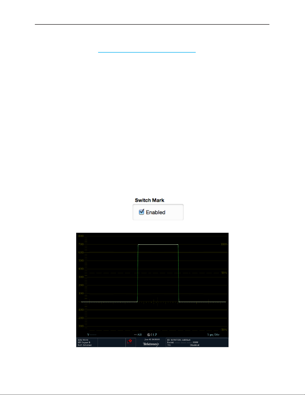
Avenue 9430 Flexible Matrix Router Installation, Configuration and Operations Guide
Switch Point Identification
As described in the section Setting Up Timing and Genlock on page 70, the video format and
horizontal and vertical timing for the Primary TSG determines timing and location of the switch point
in the vertical interval. Under SMPTE RP 168, the switch point varies from one format to another. In
general, it should occur during the middle portion of a specific line in the vertical interval. These
locations, which are as far away as possible from the SAV and EAV digital sync words, offer the best
opportunity to minimize the disturbance that is inevitably produced by switching between two digital
bit streams – even streams that are very closely timed to each other.
Note: This discussion of vertical interval switching applies ONLY to the switching that takes
place in the SDI matrix. Router outputs which are delivered through a 9435 Clean
Switch do not suffer from any disturbance when a switch takes place. This holds
true even when switching between un-timed or asynchronous sources. The 9435
Clean Switch is operating on deserialized (parallel) data where absolutely precise
alignment is possible. The switch takes place between these perfectly aligned signals
before being reserialized and sent to the output.
In order to help identify when and where the switch is taking place, the TSGs have a marking feature.
When the Switch Mark is enabled, a white pulse will be inserted on the switching line. The beginning
and ending of the pulse corresponds to the RP 168 specified switching area. This line can be viewed on
a digital waveform monitor, or on a picture monitor which offers V Delay.
Display of Y Channel for 1080i/59.94 with Switch Mark Enabled.
www.ensembledesigns.com Page 78
Page 79

Avenue 9430 Flexible Matrix Router Installation, Configuration and Operations Guide
When switching away from the TSG output with Switch Mark to a source without, there will be a
momentary frame where the switching discontinuity will be visible.
www.ensembledesigns.com Page 79
Page 80
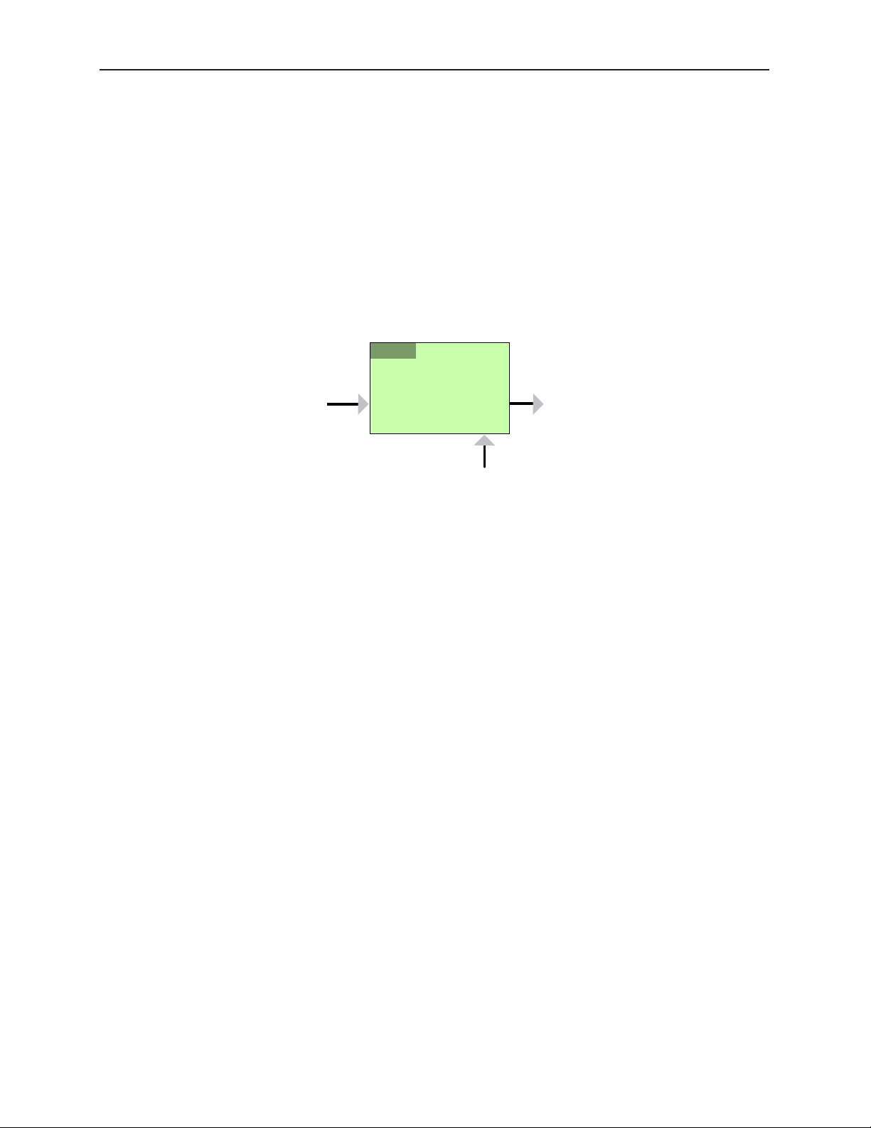
Avenue 9430 Flexible Matrix Router Installation, Configuration and Operations Guide
9435
!
/
1
2
Working with the Clean Switch Option
Each 9435 Dual Clean Switch Option provides two, independent Frame sync/Clean Switches. These
resources can be deployed within the Router in a variety of ways. The physical location of the
submodule, whether installed on the 9430 core module, or on the 9440 in Expansion 1 position (the
left hand position as viewed from the front of the frame) does not affect where or how each of these
resources are assigned or used.
Note: Only a 9440 in the Expansion 1 position supports the 9435 Dual Clean Switch.
Although it is mechanically possible to install a 9435 on a 9440 in Expansion 2, that
9435 will not appear as a resource in the configuration menus.
Clean Switch!
/ Framesync
In
Out
Genlock
A Clean Switch is a Frame sync whose input and output can be connected to different points within
the Router. The flexibility this provides allows the Clean Switch to be associated with either inputs or
outputs.
The output side of the Clean Switch is genlocked to the reference being used within the Router.
This ensures that the output is stable regardless of the input signal. Not only does this ensure clean
switching between un-timed and even asynchronous sources, it also guarantees a stable, Black output
upon loss of input.
In parallel with the video processing, 16 channels of embedded audio are silently switched as well.
Incoming audio is disembedded, sample rate converted, switched, and then embedded into the
output. The audio processing includes a delay mechanism to compensate for the delay imposed on
the video by the frame sync. This compensation ensures that the time relationship (lip-sync) between
audio and video is maintained.
The configuration of the Clean Switch includes its video format, timing, and embedded audio group
enables.
When a Clean Switch is assigned to an output port, its input is fed from the routing matrix and it drives
the output BNC connector. Any SDI source in the Router switched to this output will be presented
synchronously and timed.
www.ensembledesigns.com Page 80
Page 81

Avenue 9430 Flexible Matrix Router Installation, Configuration and Operations Guide
If an output port has been configured to Follow a Destination which has a Clean Switch assignment,
that port will also deliver the Clean Switch output. That port set to Follow will not be seen as a
destination on a control panel because there is still only one Destination.
The conceptual effect of this is to have incorporated an output DA (Distribution Amp) into the Router.
www.ensembledesigns.com Page 81
Page 82

Avenue 9430 Flexible Matrix Router Installation, Configuration and Operations Guide
By assigning a Clean Switch to a Source (input port), it is fed from that port and its output drives the
routing matrix.
This configuration is particularly useful with an asynchronous source. The frame sync feature of the
Clean Switch means that this source will now be synchronous and timed on any output it is switched
to.
This is essentially the same as placing an external frame sync upstream of that router input.
This technique can be further enhanced by the use of the Follow feature on an output port. When
a port is assigned to follow a Source which has a Clean Switch assigned, the follow output will pick
up the frame sync output, making the synchronized version of the signal available for external use
independently of any signal switching within the routing matrix.
www.ensembledesigns.com Page 82
Page 83

Avenue 9430 Flexible Matrix Router Installation, Configuration and Operations Guide
Clean Switch Configuration
There are four sets of configuration controls, one for each of the possible Clean Switches. Each Clean
Switch is configured independently.
The Clean Switch conguration page
www.ensembledesigns.com Page 83
Page 84
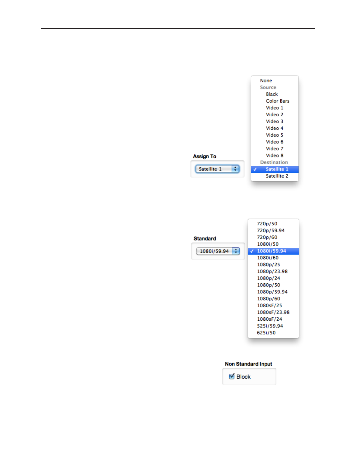
Avenue 9430 Flexible Matrix Router Installation, Configuration and Operations Guide
The configuration controls for the Clean Switches
are as follows:
Assign To
Assign the Clean Switch to any of the Sources
(Input Ports) or Destinations (Output Ports) that
have been configured in the Port Configuration
menu. Only the currently available Sources and
Destinations will be presented as choices in this
menu. Because only one CS can be assigned
to any given Source or Destination, the list
presented will not include any ports that are
already assigned to other Clean Switches. In order
to change assignments to move a port from
one CS to another CS, you must first release the
original assignment by selecting “None.”
Standard
Select the desired operating format and frame
rate. Only input signals matching that Standard
will be processed by the Clean Switch.
If a source in a different format is selected, the CS
will be bypassed and the source will be switched
to the output without any processing. This applies
for both Input and Output configurations.
Non Standard Blocking
When Non Standard Inputs are blocked, the
output of the Clean Switch will go to Black when
a differing input is presented.
www.ensembledesigns.com Page 84
Page 85

Avenue 9430 Flexible Matrix Router Installation, Configuration and Operations Guide
Vertical and Horizontal Timing
This control adjusts the timing of the Clean Switch relative to the genlock reference. Setting the H and
V parameters to 0 will “zero” time the CS, matching it to the reference. Negative values will cause the
CS to be early with respect to the reference; positive values will make the Clean Switch output later in
time.
The best or most appropriate setting for the timing controls will depend upon the way in which the CS
is to be used and the nature of the video inputs.
Note: A video frame sync imposes delay on a video signal passing through it in order
to align that input to the user adjusted output timing. The amount of delay is a
function of the difference in timing between the incoming video and the output
of the frame sync. The frame sync can only add delay to the video in order to make
up that difference, and the amount will change automatically in accordance with
the timing of the input signal. If the input signal is one line early compared to the
output, the frame sync will add only one line of delay. But if the incoming video is
just one line late, the frame sync will add nearly an entire frame (less one line) to
bring the signal into time. If the input is asynchronous, its timing will be changing
(drifting) continuously. And in that case, the delay imposed by the frame sync will
vary continuously between (near) zero and one frame.
When a Clean Switch is being used as a pre-selector to a production switcher, the CS output timing
must fall within the input auto-time window of the switcher. In general, this will be accomplished by
setting the Clean Switch H and V parameters to zero.
If the Clean Switch is feeding on-set monitors in a live environment from sources also used on
the production switcher, it is generally desirable to minimize the delay on those monitors. This is
accomplished by setting the Vertical timing of the Clean Switch to a small positive value. Setting this
parameter to +4 lines will typically guarantee that the sources (which have near zero timing) will
only experience 2 or 3 lines of delay. Since most production switchers have a forward delay of 1, 2, or
3 lines, a setting of +4 lines on the Clean Switch will also allow the switcher output to be used with
minimum delay.
www.ensembledesigns.com Page 85
Page 86

Avenue 9430 Flexible Matrix Router Installation, Configuration and Operations Guide
Audio Embed
The Clean Switch supports 16 channels (four groups) of embedded audio. In order for the Clean
Switch output to have a consistent configuration of audio, regardless of what is present on the input,
individual enables are provided for each group.
The Clean Switch output will always contain the enabled groups, but channels that are not present
in the input will simply be silent. In this way, switching between sources with differing audio
configurations will produce smooth, silent transitions.
www.ensembledesigns.com Page 86
Page 87

Avenue 9430 Flexible Matrix Router Installation, Configuration and Operations Guide
Chapter 5: Operations and Step-by-Step Procedures
In this Chapter
This chapter provides complete step-by-step procedures for each task that you can perform with the
Router using the following control choices:
• Router Control Panel (5830) Operation
• Router Operation with the Web Browser Interface
You can use the web browser interface on a computer or on an iPad.
For serial protocols through TCP/IP, RS-232 and SNMP, please see Chapter 6: External Control on page
96.
Router Control Panel (5830) Operation
Orientation of Front Panel
The Router Control Panel has an LCD Display on the left. The two small round buttons to the left of the
LCD Display are used for accessing ancillary data.
By default, the top row of buttons is used for Sources and illuminates red, while the bottom row of
buttons is used for Destinations and lluminates green. However, if more than 16 Sources are being
used, the buttons in the lower row can be used for Sources and will illuminate red as needed. Similarly,
if more than 16 Destinations are being used, the buttons in the upper row can be used for Destinations
and will illuminate green as needed.
The Direct and Take buttons are on the far right side of the front panel. The Direct button is on top;
the Take button is on the bottom.
Performing Takes with the Router Control Panel
While performing a take is a straight forward task, it can be done using more than one method.
To Perform a Take by Selecting a Source and a Destination
1. Select a Source by pressing one of the red Source buttons. The button illuminates more brightly
to indicate that it is selected. The LCD display shows the realtime video thumbnail image of the
Source you selected so that you can visually verify the content.
2. Select a Destination by pressing one of the green Destination buttons. The button illuminates
more brightly to indicate that it is selected. As soon as you have selected both a Source and a
Destination, the blue Take button, located in the lower right part of the router control panel,
illuminates, indicating that the Router is ready for a Take.
3. Press the Take button. Your chosen Source is routed to the Destination that you selected. The LCD
display continues to show the realtime video thumbnail image that is currently being routed to
your chosen Destination. The Take button is no longer illuminated.
www.ensembledesigns.com Page 87
Page 88

Avenue 9430 Flexible Matrix Router Installation, Configuration and Operations Guide
To Perform a Take by Selecting Only a New Source
As long as the Destination that you want is already selected, you can perform a Take by selecting a
new Source, then pressing the Take button.
1. Leaving the Destination selection unchanged, select a new Source. The Source button illuminates
to indicate that it is selected. The LCD display shows the real time video thumbnail image of the
Source you selected so that you can visually verify the content.
2. Press the Take button. Your newly selected Source is now routed to the Destination. The LCD
display continues to show the real time video thumbnail image that is currently being routed to
your chosen Destination. The Take button is no longer illuminated.
Performing Direct Takes with the Router Control Panel
In Direct Take mode, you leave the same Destination selected while choosing a series of different
Sources. There is no need to press the Take button when in Direct Take mode.
To Perform a Direct Take
1. Press the Direct button in the upper far right area of the router control panel. The Direct button
illuminates to indicate that it is active.
2. Press a Destination button.
3. Press a Source button. The Destination immediately reflects your newly selected Source.
As long as you remain in Direct Take mode, you can continue to change Sources for the same
Destination by pressing one Source button at a time in sequence.
To Exit Direct Take Mode
Press the Direct button in the upper far right area of the router control panel. The Direct button is no
longer illuminated.
Accessing Ancillary Data with the Router Control Panel
For each video source, the Router detects and measures key parameters such as synchronicity, timing,
line and frame rate, embedded audio presence/absence, closed caption information, and timecode
data.
To Access Ancillary Data
For the Source currently showing in the LCD display, use the two small buttons located to the left of
the LCD to navigate among the screens that show ancillary data. There are three ancillary data screens.
Use either button to navigate among these screens.
www.ensembledesigns.com Page 88
Page 89

Avenue 9430 Flexible Matrix Router Installation, Configuration and Operations Guide
Router Operation with the Web Browser Interface
You can control the Router through its web browser user interface. You can perform takes, direct takes,
gang, and gang combined with direct takes.
Prerequisites
Before you can access the Router through a web browser, you need to have access to an authenticated
Control Point and the Router’s IP address. For further details about these requirements, please see the
following sections:
• Assigning the Router a New IP Address on page 45
• Establishing Control Points and Access Authentication on page 63
• First Method: Requesting Access from a Control Point on page 68
Accessing the Web Browser Control Interface
To access the web browser control interface, enter the Router’s IP address into the browser’s address
bar. The Router’s interface displays, showing Sources in the upper area and Destinations in the lower
area.
The Web Browser Interface
www.ensembledesigns.com Page 89
Page 90

Avenue 9430 Flexible Matrix Router Installation, Configuration and Operations Guide
About the Web Browser Interface
The web browser interface is organized into an upper area for Sources, and a lower area for
Destinations. The relative size of the upper and lower areas can be resized by clicking and dragging
along the location where the background color changes to differentiate the upper and lower areas of
the window.
The thumbnail images for Sources display their names on the lower part of each Source image frame.
The thumbnail images for Destinations display their names on the lower part of each Destination
image frame. Additionally, Destination thumbnails display the currently mapped Source name along
the top of the frame.
See the following examples:
Source Example: The name of the
Source displays on the bottom of the
frame.
Destination Example: The name of
the Source mapped to this Destination
displays on the top of the frame; the
name of the Destination displays on
the bottom of the frame.
The name of each Source and each Destination is determined during Router configuration. For further
details on Source and Destination naming, see To Configure the Router’s Ports on page 57.
www.ensembledesigns.com Page 90
Page 91

Avenue 9430 Flexible Matrix Router Installation, Configuration and Operations Guide
Preferences
Use the Preferences button, located in the upper right area of the browser window, to customize how
the thumbnail images display. Sources and Destinations can be sized independently. Choose from
small, medium and large.
For Sources, you can also choose to display ancillary data next to each thumbnail or instead of each
thumbnail. It is the same ancillary data that is available through the LCD display of the Router Control
Panel (5830).
www.ensembledesigns.com Page 91
Page 92
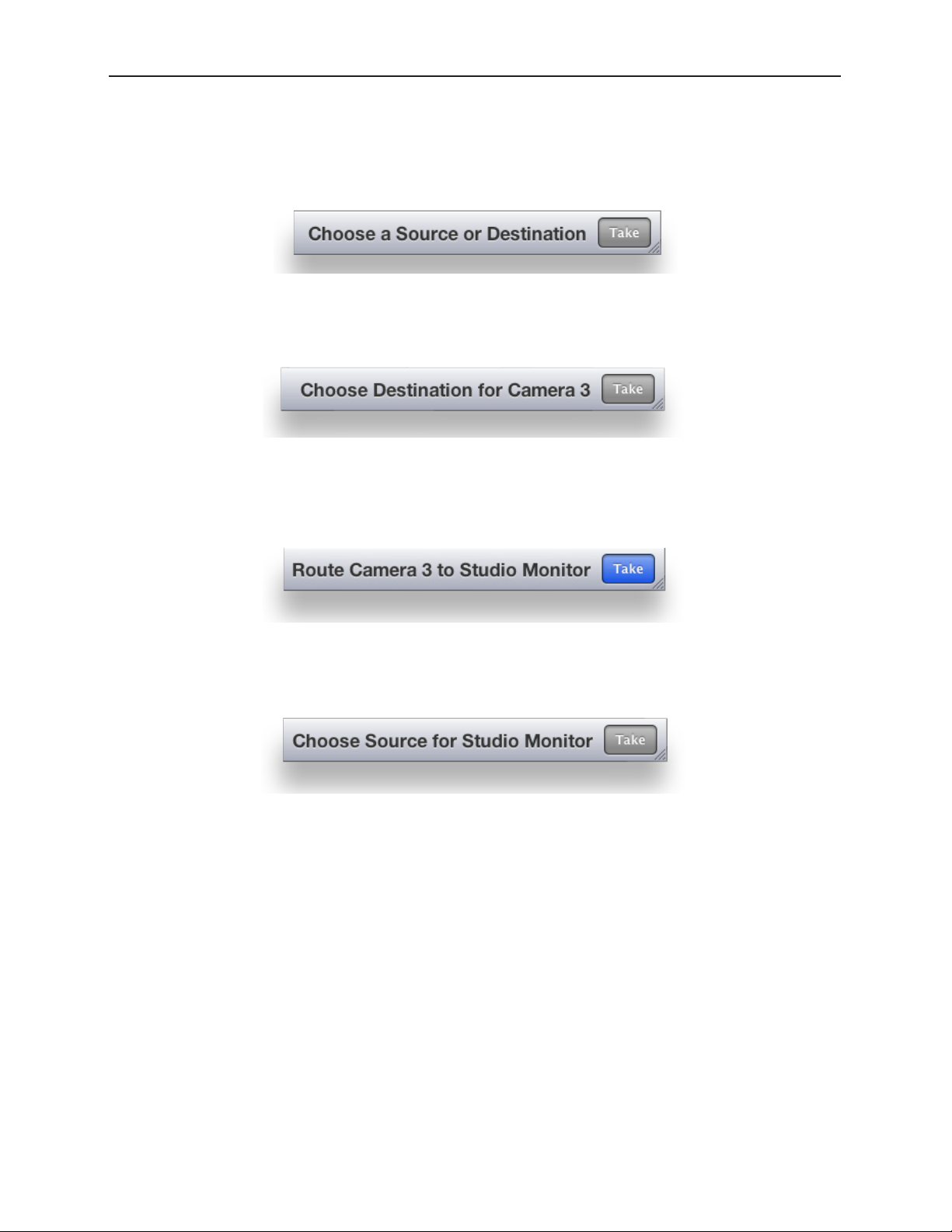
Avenue 9430 Flexible Matrix Router Installation, Configuration and Operations Guide
Message Bar
A Message Bar located in the lower right area of the browser window reflects your actions with respect
to Sources and Destinations. For example, before you have taken any action, the Message Bar displays
the message “Choose a Source or Destination.”
After selecting a Source named “Camera 3,” the Message Bar now says: “Choose Destination for Camera
3.”
If you then select a Destination named “Studio Monitor,” the Message Bar now says: “Route Camera 3 to
Studio Monitor.” Note that the Take button is now blue, indicating that the Router is ready for a Take.
On the other hand, if you have selected the Destination named “Studio Monitor,” and haven’t yet
selected a Source, the Message Bar will say: “Choose Source for Studio Monitor.”
www.ensembledesigns.com Page 92
Page 93

Avenue 9430 Flexible Matrix Router Installation, Configuration and Operations Guide
Performing Takes with a Web Browser
While performing a take is a straight forward task, it can be done using more than one method.
To Perform a Take by Selecting a Source and a Destination
1. Select a Source by clicking one of the Source thumbnail images. The thumbnail frame turns red to
indicate that it is selected.
2. Select a Destination by clicking one of the Destination thumbnail images. The thumbnail frame
turns green to indicate that it is selected. As soon as you have selected both a Source and a
Destination, the Take button turns blue, indicating that the Router is ready for a Take.
3. Click Take in the lower right area of the web browser. Your chosen Source is routed to the
Destination you selected. The Destination thumbnail image updates to reflect your currently
selected Source. The Ta ke button is now greyed out.
To Perform a Take by Selecting Only a New Source
As long as the Destination that you want is already selected, you can do a Take by selecting a new
Source, then clicking Take.
1. Leaving the Destination selection unchanged, select a new Source.
2. Click Take . Your chosen Source is routed to the Destination. The Destination thumbnail image
updates to reflect your new Source selection.
www.ensembledesigns.com Page 93
Page 94

Avenue 9430 Flexible Matrix Router Installation, Configuration and Operations Guide
Performing Direct Takes with a Web Browser
In Direct Take mode, you leave the same Destination selected while selecting different Sources with
only one click. There is no need to click the Take button when in Direct Take mode.
To Perform a Direct Take
1. Click Direct in the lower left area of the browser window. The Direct button turns orange.
2. Select a Destination.
3. Select a Source. The Source is immediately routed to the Destination. The Destination thumbnail
image reflects your newly selected Source.
As long as you remain in Direct Take mode, you can continue to change Sources for the same
Destination with only one click.
To Exit Direct Take Mode
Click Direct in the lower left area of the browser window. The Direct button is now greyed out,
indicating that you are no longer in Direct Take mode.
www.ensembledesigns.com Page 94
Page 95

Avenue 9430 Flexible Matrix Router Installation, Configuration and Operations Guide
Performing Gang Takes with a Web Browser
Gang Takes involve routing one Source at a time to a set of Destinations.
To Perform a Gang Take
1. Click Gang in the lower left area of the browser window. The Gang button turns orange.
2. Select a Source by clicking one of the Source thumbnail images. The thumbnail frame turns red to
indicate that it is selected.
3. Select a set of Destinations by clicking multiple Destination thumbnail images sequentially. The
first thumbnail frame you select turns green; the remaining thumbnails you select turn yellow.
4. Click Take in the lower right area of the web browser. The Source is routed to the set of
Destinations. The set of selected Destination thumbnail images updates to reflect your selected
Source. The Take button is now greyed out.
You can continue to perform gang takes in this manner as long as you are in Gang mode.
To Exit Gang Mode
Click Gang in the lower left area of the browser window. The Gang button is now greyed out,
indicating that you are no longer in Gang Mode.
Performing Direct Gang Takes with a Web Browser
Direct Gang Takes involve routing one Source at a time to a set of Destinations instantaneously,
without having to use the Take button.
To Perform a Direct Gang Take
1. Click Direct in the lower left area of the browser window. The Direct button turns orange.
2. Click Gang in the lower left area of the browser window. The Gang button turns orange.
3. Select a set of Destinations by clicking multiple Destination thumbnail images sequentially. The
first thumbnail frame you select turns green; the remaining thumbnails you select turn yellow.
4. Select a Source by clicking one of the Source thumbnail images. The Source is routed to the set of
Destinations. The set of selected Destination thumbnail images updates to reflect your selected
Source.
To Exit Direct Gang Mode
Click Direct and Gang in the lower left area of the browser window. The Direct and Gang buttons are
now greyed out, indicating that you are no longer in Direct Gang Mode.
www.ensembledesigns.com Page 95
Page 96

Avenue 9430 Flexible Matrix Router Installation, Configuration and Operations Guide
Chapter 6: External Control
The Router’s Approach to Control Integration
The Router provides control from external systems like automation and event controllers. As there is
a significant legacy of protocols and usage models in current practice, the Router supports a variety
of external control protocols, offering a range of commands and control capabilities in order to make
control integration as easy as possible. These protocols can be used with both the RS-232 and Ethernet
physical interfaces. This approach generally allows the Router to be used without adaption in current
systems.
RS-232 Interface and 9-Pin D Connector Pin Out
One leg of the RS-232 and 100Mb Ethernet Interface Adaptor Cable, or “Y” cable, provides a 9-pin
female D connector for the RS-232 interface. The pin-out for that connector is as follows:
9 pin female D connector
5
Control
9
9 7 6
8
15 4 3 2
1
6
PIN FUNCTION
1
2 TX - Data output
3 RX - Data input
4
5 Gnd
6
7
8
9
Router Control Panel (5830) GPI Inputs
The Router Control Panel provides 8 GPI contact closure inputs. These can be configured on a specific
Router Control Panel to integrate it with other equipment. When used in a camera shading installation
as the reference monitor input selector, GPI connections from the joystick button on the camera
control head can make camera selections. In a master control bypass application, a GPI “panic button”
can be used to force the system into bypass.
Overview of Supported Control Protocols
The Router supports the following control protocols:
• Avenue FMR
• Grass Valley TenXL
• Grass Valley 100
• Generic ASCII
www.ensembledesigns.com Page 96
Page 97

Avenue 9430 Flexible Matrix Router Installation, Configuration and Operations Guide
• RS-232
• Telnet
• TCP/IP
These control protocols are briefly described below. For detailed documentation of the automation
protocols, please see “Appendix A: Automation Protocols” on page 105.
Avenue FMR
Unique to the Avenue 9430/9440 Flexible Matrix Router, this is an ASCII (human readable) control
protocol with an extensive command set, offering very useful and powerful external control
functionality. These interfaces are enabled, disabled and configured through the External Control tab
on the web configuration tool.
Simultaneous Support for Multiple Protocols
These protocols are accessible over three different interfaces. Each interface is independent, allowing
simultaneous support for different protocols on different interfaces.
Control Profiles for External Interfaces
An interface is “connected” to the Router through a Control Profile – similar to a physical control
panel. This allows for the choice of available Sources and Destinations, and the order in which they
are mapped to the interface protocol to be customized on the Router rather than on the controlling
device.
Grass Valley TenXL
The Router supports both the ASCII (human readable) and SMPTE ESbus (binary) variants of this
protocol. Supports only source to destination control.
Grass Valley 100
The Router supports SMPTE ESbus with and without the “break” character requirement. Though widely
implemented, this protocol is limited in usefulness with a router because it supports only 4 output
busses. Supports only source to destination control.
Generic ASCII
The Router supports this simple human readable protocol with both space and comma variable
separators. Supports source to destination routing and salvos.
RS-232
The conventional RS-232 serial interface is provided from the 9430 module through the control
breakout cable. This interface can operate from 1200 to 115,200 baud (bits per second).
Telnet
Using the Ethernet port on the control breakout cable, you can open a Unix-style Telnet session with
the 9430 module. As a text-oriented communications facility, Telnet is only suited to ASCII protocols. It
provides easy access from a distance (even a great distance) and can be of particular utility for system
www.ensembledesigns.com Page 97
Page 98

Avenue 9430 Flexible Matrix Router Installation, Configuration and Operations Guide
debugging. If the Telnet interface is disabled in the External Control configuration, the 9430 will refuse
the connection.
TCP/IP
You can open a TCP/IP session at a private port number (to be specified) to enable network control. As
with Telnet, this interface must be enabled in the External Control configuration in order for the 9430
to accept the connection. This is the preferred network equivalent to RS-232 and it works with both
ASCII and binary protocols and command sets.
Additional GPI and Serial Connections through JL Cooper eBOX
Additional GPI and Serial connections for the Router can be made through the JLCooper eBOX, a thirdparty device. It provides 24 GPI inputs, 24 GPI outputs and 4 serial connectors. Please see Using the JL
Cooper eBOX with Ensemble Designs Avenue Equipment for a detailed description of the process of
configuring the Router for GPIO (general purpose input/output) functionality using the eBOX.
SNMP Interface
A Simple Network Management Protocol (SNMP) agent in the 9430 supports Control and Status
queries from an SNMP manager.
Programming Reference Document
The Management Information Base (MIB) document, specific to the Router, is a required programming
reference while customizing the SNMP manager. You can either download the MIB document directly
from the Router’s web interface or request it from Ensemble Designs.
The SNMP interface will be active only if enabled through External Control configuration. SNMP
support will not be available on initial product shipments, but will be provided by a subsequent
system software upgrade.
Software Development Kit (SDK)
When control requirements go beyond straight forward functions, such as source to destination
routing and salvo execution, you may need to develop an interface more specific to your needs. To
that end, Ensemble Designs will be releasing an interface design guide, or software development kit
(SDK), to support such efforts.
Accessing Features Unique to the 9430 Flexible Matrix Router
That more extensive interface will be necessary when you need to access features unique to the
Flexible Matrix Router, such as:
• reading the input signal metadata;
• controlling the internal TSGs; and
• capturing video thumbnails remotely
www.ensembledesigns.com Page 98
Page 99

Avenue 9430 Flexible Matrix Router Installation, Configuration and Operations Guide
Configuring External Control
For each of the enabled interfaces, select the desired protocol. The mapping of that protocol to
Sources and Destinations will be controlled by the Profile that is assigned to the interface. Any Profile
can be edited to modify the Sources and Destinations that are available to it and the order in which
they are listed. For more information, see Creating and Editing Profiles on page 59.
www.ensembledesigns.com Page 99
Page 100

Avenue 9430 Flexible Matrix Router Installation, Configuration and Operations Guide
Chapter 7: Maintenance and Troubleshooting
This chapter addresses certain known issues and possible issues that new users may encounter while
becoming familiar with using the Flexible Matrix Router.
Troubleshooting the Router Module (9430)
Cannot Connect to the Router
If you are having difficulty connecting to the Router, check that the IP addresses of the Router and the
computer or device are not in conflict. Check also that the cabling is correct.
• Review the instructions in Initially Connecting to the Router on page 40 to make sure you
have configured the IP addresses correctly.
• See also Router Control Connections on page 32 to make sure you have correctly cabled the
control connections between the Router and the controlling computer.
Router Not Running
To Determine if the Router is Running
Open the front door of the Avenue frame and check the Run light on the front panel of the 9430. When
the Router is running properly, the Run light will be blinking on and off. Note that the rate of blinking
will not match the rate of blinking of the Run lights of other modules running in the Avenue frame.
However, if the Run light stops blinking, whether it remains on or off, it means that the Router has
stopped.
Resetting the Router
There are two types of resets for the 9430. One is a reboot. The other is a reset to the factory default
settings.
Rebooting
To reboot the 9430, use something with a fine point, such as a paperclip, to press into the small “Reset”
hole on the lower part of the front panel. Press once briefly and release. The module will reboot. A
reboot typically takes a few minutes. After the reboot is complete, the Run light will resume blinking.
Resetting to Factory Default Settings
If you want to reset your module to factory default settings, use something with a fine point, such as a
paperclip, to press and hold into the small “Reset” hole on the lower part of the front panel. Continue
holding the Reset button in its pressed in position until you see all of the Input lights on the front
panel illuminate several times (approximately 15 seconds), then release. The 9430 will reboot with
factory default settings. Note that the IP address and all other settings will have to be reconfigured.
Authorized Control Point Unable to Connect to Router
If you are using an authorized Control Point but you are seeing the message “Control Point Disabled,”
check to make sure that the Control Point has been assigned a Profile. Without an assigned Profile, it is
www.ensembledesigns.com Page 100
 Loading...