

Page 1
Model 7400 HD/SD and
Model 9400 3G/HD/SD
Sync Pulse Generator and
Test Signal Generator
User Guide
including 7400-GPS Option
Revision 1.5 SW v2.2.7
Page 2
Clearly, Ensemble wants to be in the broadcast equipment business. It’s so rare anymore to nd a company of this
caliber that has not been gobbled up by a large corporation. They are privately held so they don’t have to please the
money people. They really put their eorts into building products and working with customers.
I’m really happy with the Avenue products and Ensemble’s service, and even more important my engineers are happy.
We’ve continued to upgrade the product and add more cards. We will be rebuilding our production control room and
we will use Avenue again.
~ Don McKay, Vice President Engineering, Oregon Public Broadcasting
Who is Ensemble Designs?
By Engineers, For Engineers
In 1989, a former television station engineer who loved
designing and building video equipment, decided to
start a new company. He relished the idea of taking
an existing group of equipment and adding a few
special pieces in order to create an even more elegant
Avenue frames handle 270 Mb/s,
1.5 Gb/s and 3 Gb/s signals,
audio and MPEG signals. Used
worldwide in broadcast, mobile,
production, and post.
ensemble. So, he designed and built his rst product and
the company was born.
Focused On What You Need
As the company has grown, more former TV station
engineers have joined Ensemble Designs and this wealth
of practical experience fuels the company’s innovation.
Everyone at the company is focused on providing the
very equipment you need to complete your ensemble
of video and audio gear. We oer those special pieces
that tie everything together so that when combined, the
whole ensemble is exactly what you need.
Notably Great Service for You
We listen to you – just tell us what you need and we’ll
do our best to build it. We are completely focused on
you and the equipment you need. Being privately held
means we don’t have to worry about a big board of
directors or anything else that might take attention away
from real business. And, you can be sure that when you
call a real person will answer the phone. We love this
business and we’re here to stay.
Bricks and Mortar of Your Facility
The bricks and mortar of a facility include pieces like
up/downconverters, audio embedders, video converters,
routers, protection switches and SPGs for SD, HD and
3Gb/s. That’s what we’re focused on, that’s all we do
– we make proven and reliable signal processing and
infrastructure gear for broadcasters worldwide, for you.
We’re focused on
processing gear–
3G/HD/SD/ASI video,
audio and optical modules.
Come on by and visit us.
Drop in for lunch and a tour!
Shipped with care to
television broadcasters
and video facilities all
over the world.
Page 3

Model 7400 HD/SD and Model 9400 3G/HD/SD Sync Pulse Generator and Test Signal Generator
Contents
Module Overview 5
7400 and 9400 SPG/TSG—Reliable and Easy-To-Use 5
Favorite Test Patterns 5
Customizable Test Patterns 5
Audio Generators 6
Multiple Timecode Generators 6
7400-GPS Option for the Ultimate Precision Reference 7
Functional Block Diagram 8
Applications 9
A Complete SPG and TSG System 9
Broadcast 10
Mobile Applications 11
Post Production 12
Custom Test Patterns 12
Timecode 13
How the Timecode is Generated 13
Analog Timecode 13
Vertical Interval Timecode (VITC) and Digital Vertical Interval Timecode (DVITC) 14
Locking to a Black Burst Signal with VITC 14
Audio Generation and Routing 15
Audio Generators 15
Support for Analog and Digital Audio 15
Sixteen Independently Programmable Audio Channels Per Generator 15
Audio Embedded in the SDI Outputs 15
Installation 17
7400-GPS Option Field Installation Procedure 17
7400-GPS Option Kit 17
Securing the 7400-GPS Option Submodule to the 7400 or 9400 Main Module 18
Connecting the Cables between the 7400-GPS Option Submodule and the
7400 or 9400 Main Module 19
H1 Jumper Positioning 20
Safety and Outdoor Antenna Grounding 21
www.ensembledesigns.com
Avenue 7400 and 9400 - Page 3
Page 4

Model 7400 HD/SD and Model 9400 3G/HD/SD Sync Pulse Generator and Test Signal Generator
Cabling 22
Generator A 24
Generator B 24
Module Conguration and Control 25
Front Panel Controls and Indicators 25
Avenue PC and Touch Screen Remote Conguration 26
7400 and 9400 Avenue PC and Touch Screen Menus 27
Sync Pulse Generator A Menu 27
Test Signal Generator A Menu 29
Timing A Menu 32
Programmable Output 1 A Menu 33
Programmable Outputs 2 A and 3 A Menu 35
Audio Generator A Menu 38
Timecode A Menu 40
Misc A Menu: Setting the Slate, Closed Caption, and Aspect Ratio Parameters 42
Sync Pulse Generator B Menu 44
Test Signal Generator B Menu 46
Timing B Menu 49
Programmable Output 1 B Menu 50
Programmable Output 2 B and 3 B Menu 52
Audio Generator B Menu 55
Timecode B Menu 57
Misc B Menu: Setting the Slate, Closed Caption, and Aspect Ratio Parameters 59
Global Menu 61
GPS Menu 63
Storage Menu 66
Troubleshooting 67
No Generator A or Generator B LED indication 67
Cannot control module 67
Module controls are grayed out 67
No signal out of module 67
Software Updating 68
Warranty and Factory Service 69
Specications for Models 7400 and 9400 70
Glossary 73
www.ensembledesigns.com
Avenue 7400 and 9400 - Page 4
Page 5

Model 7400 HD/SD and Model 9400 3G/HD/SD Sync Pulse Generator and Test Signal Generator
Module Overview
7400 and 9400 SPG/TSG—Reliable and Easy-To-Use
The 7400 HD/SD and the 9400 3G/HD/SD Sync Generator and Test Signal Generator provide a stable
timing source that is perfect for local reference generation in broadcast, remote trucks and post.
HD SDI, SD SDI, analog composite, HD Tri-Level Sync, timecode, AES audio and analog audio reference
outputs are generated.
The 7400 and 9400 can operate from an internal precision frequency reference as a stand-alone Master
Sync Generator or lock to a video reference or 10 MHz precision reference. Alternately, the 7400-GPS
option can be used.
The 7400 and 9400 can output multiple formats of Tri-Level Sync, HD SDI test signals (1.5 Gb/s for
the 7400, and 3 Gb/s and 1.5 Gb/s for the 9400), SD composite and SDI test signals, and color black
reference. The 7400 and 9400 can simultaneously deliver both 525 (NTSC) and 625 (PAL) based signals.
Color framing tracks the reference signal. All of the video outputs are derived from the same time base
and can be timed with respect to each other. The 7400 and 9400 each have two identical generators,
Generator A and Generator B, both with a variety of outputs. Each set of outputs can be timed with
respect to the reference to any point in the television frame. All of the Outputs from a particular
Generator must be selected within the same frame rate family:
• 50 Hz (625) Derived Family: 1080i/50, 720p/50, 1080p/25, 1080sF/25, 625i/50
• 59.94 Hz (525) Derived Family: 1080i/59.94, 720p/59.94, 1080p/23.98, 1080sF/23.98,
525i/59.94
• 60 Hz Derived Family: 1080i/60, 720p/60, 1080p/24, 1080sF/24
The Avenue Frame features a retainer bar to ensure that modules remain properly seated even in the
most demanding mobile environments.
Favorite Test Patterns
There are over 30 test signals including: Full and Split Field Bars at 75% and 100% with Pluge, Black,
Flat Field, Pulse and Window, Ramp, Crosshatch, Safe Title, Blanking Markers, Cosite, Checkeld,
Pathogenic, and 5 Step. The Cyclops feature adds a motion element to the selected video test signal
to assist in locating a signal that might be frozen in a frame sync somewhere in the signal chain. An ID
slate with user programmable text can overlay the test pattern.
Customizable Test Patterns
In addition to the standard suite of test patterns, users can create custom test patterns on a computer.
Simply transfer test patterns to the included Secure Digital ash memory card using Avenue Logo
software and a standard card reader, then insert the memory card into the 7400 or 9400. Test patterns
can include motion.
www.ensembledesigns.com
Avenue 7400 and 9400 - Page 5
Page 6

Model 7400 HD/SD and Model 9400 3G/HD/SD Sync Pulse Generator and Test Signal Generator
Audio Generators
The 7400 and 9400 provide extensive support for analog and digital audio. Because all of the video
outputs can be locked to a common time base, the AES digital audio outputs are always synchronous
with all of the video outputs – regardless of format. Multiple tone generators make it easy to identify
multi-channel content. This bitstream will be included in the set of signals that can be embedded into
the test signal outputs.
The audio section of each generator supports sixteen audio channels. The content of each channel is
independently programmable. Choices include adjustable frequency tone generators, tone sweeps,
Silence, Timecode, Audio Clip playback from Secure Digital Card, and the external AES input. Left/Right
Channel ID that synchronizes to the Cyclops feature can also be selected.
All sixteen of these channels can be embedded in the SDI outputs. Each AES output can select
from any of the 8 pairs that make up these 16 channels. Similarly, the stereo analog output of each
generator can be driven from any of these audio signal pairs.
Multiple Timecode Generators
Multiple timecode generators make the 7400 and 9400 convenient for post applications. Timecode
is delivered as LTC (both 75 Ohm BNC and 110 Ohm Balanced), VITC, and DVITC. One generator
can be congured to produce 525/59.94 drop frame timecode while the other generator is making
1080sF/23.98.
www.ensembledesigns.com
Avenue 7400 and 9400 - Page 6
Page 7
Model 7400 HD/SD and Model 9400 3G/HD/SD Sync Pulse Generator and Test Signal Generator
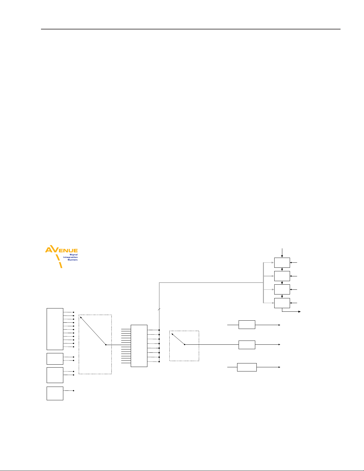
Genlock Input will accept:
525 or 625 Composite
12 types of TLS
10 MHz 1 V P-P Sine or Square
External
Reference
Input
Frame
Master
Reference
Avenue 7400-GPS Option
In
GPS Receiver
User Test Patterns loaded through
built-in Secure Digital (SD) Card Interface
10 MHz Out
Time
One
generator
can lock to
the other
Generator A
Generator B
Sync
Reference
Selection
&
Timing
Adjustments
Sync
Reference
Selection
&
Timing
Adjustments
Output
Selection
Sync
Separator
Audio
Embed
DVITC
Insert
3G/HD/SD TSG
SDI Out
(3G on 9400 only)
Programmable
Out 1
Composite/TLS Out
Programmable
Out 2
Programmable
Out 3
Stereo
DAC
Stereo
DAC
Internal
Precision
Standard
VITC
Reader
Test
Signal
Generator
608/708
Insert
Caption
Generator
L21 Insert
10 MHz
Gen
Slate/
Cyclops
Generator
Output
Selection
TLS
Gen 1
Composite
Encoder
HD/SD
Serializer
TLS
Gen 2
AES
Encode
VITC
Insert
Timecode
Generator
Wordclock
Generator
Audio
Gen/Select
Output
Selection
Audio
Embed
DVITC
Insert
3G/HD/SD TSG
SDI Out
(3G on 9400 only)
Programmable
Out 1
Composite/TLS Out
Programmable
Out 2
Programmable
Out 3
Test
Signal
Generator
608/708
Insert
Caption
Generator
L21 Insert
Source
Select
10 MHz
Gen
Slate/
Cyclops
Generator
TLS
Gen 1
Composite
Encoder
HD/SD
Serializer
AES
Encode
VITC
Insert
Timecode
Generator
Wordclock
Generator
Audio
Gen/Select
Source
Select
TLS
Gen 2
SD Card
SD Card
Output
Selection
7400-GPS Option for the Ultimate Precision Reference
For the ultimate in precision, the 7400-GPS option can be used with the 7400 and 9400 modules. The
purpose of this GPS option is to provide an extremely precise frequency reference. The oscillator on
the 7400-GPS is more accurate than a typical internal precision standard and is equivalent in accuracy
to an atomic standard. Increased frequency accuracy makes it possible to frame synchronize signals
between dierent facilities with virtually no dropped or doubled frames. The GPS option also provides
precise time of day information, which can be used to drive the 7400 or 9400 module’s internal
timecode generators.
The 7400-GPS option seamlessly integrates into the Avenue system by plugging directly onto the 7400
and 9400 modules. It can be easily installed in the eld. The 7400-GPS option consists of a compact,
weatherproof antenna (with internal high-gain pre-amp) and a receiver sub module which mounts
directly to the 7400 or 9400 module. The included GPS antenna mounts onto standard 3/4” threaded
pipe, metal or plastic. Connection from the F-style coaxial tting on the antenna to the appropriate
BNC on the Avenue Frame can be made with customer supplied standard 75 ohm cable. The coax
cable can be routed through the center of the pipe for a completely waterproof installation. When low
loss cable such as Belden 1694A is used, the antenna can be placed up to 200 feet (60 meters) from the
frame. Ideally, the antenna is mounted outdoors where it has an unobstructed view of the sky.
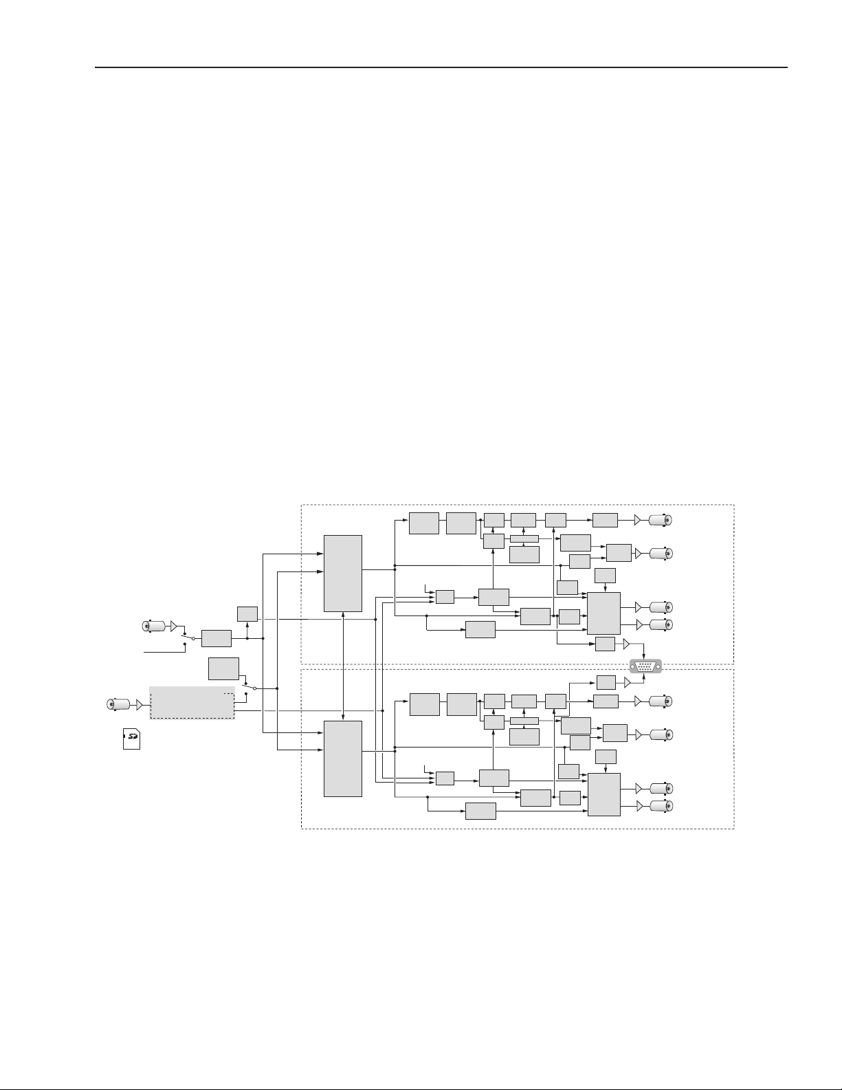
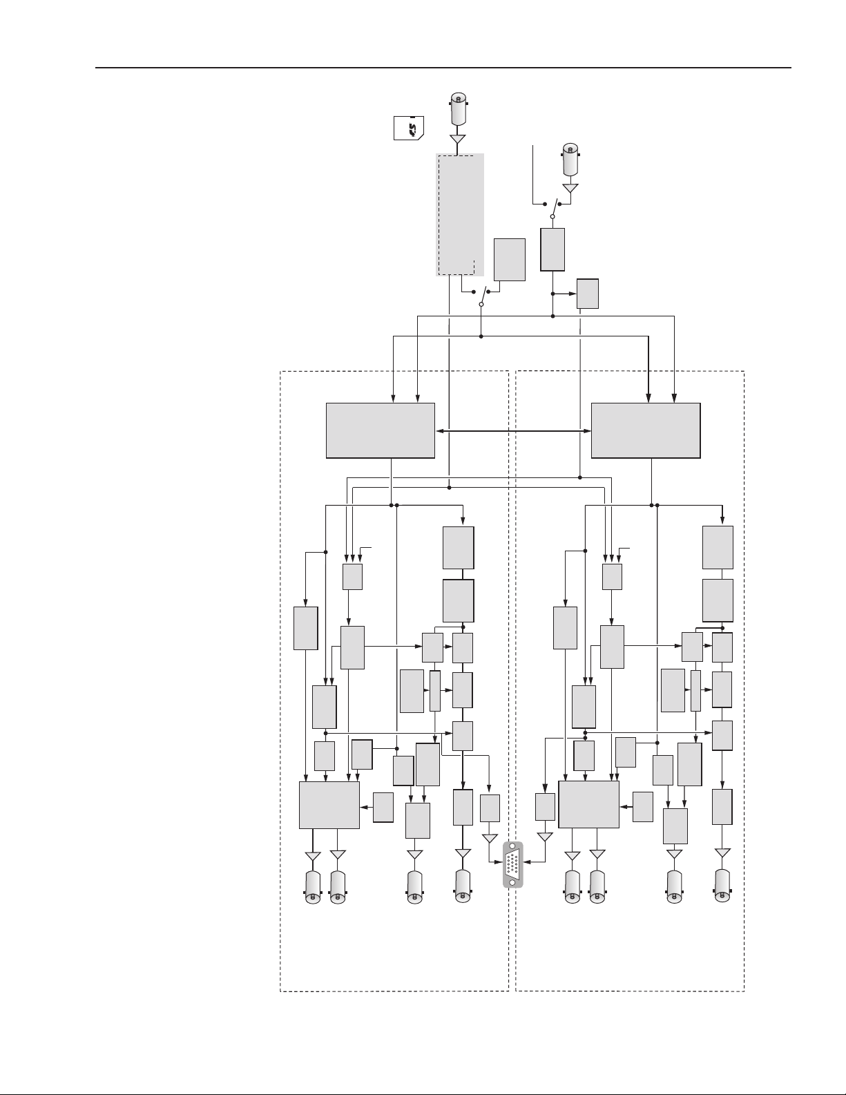
For your reference a functional block diagram for the 7400 and 9400 follows, rst as a portrait view and
then as a full page landscape view.
www.ensembledesigns.com
Functional Block Diagram, portrait view
Avenue 7400 and 9400 - Page 7
Page 8
Model 7400 HD/SD and Model 9400 3G/HD/SD Sync Pulse Generator and Test Signal Generator
Genlock Input will accept:
525 or 625 Composite
12 types of TLS
10 MHz 1 V P-P Sine or Square
External
Reference
Input
Frame
Master
Reference
Avenue 7400-GPS Option
In
GPS Receiver
User Test Patterns loaded through
built-in Secure Digital (SD) Card Interface
10 MHz Out
Time
One
generator
can lock to
the other
Generator A
Generator B
Sync
Reference
Selection
&
Timing
Adjustments
Sync
Reference
Selection
&
Timing
Adjustments
Output
Selection
Sync
Separator
Audio
Embed
DVITC
Insert
3G/HD/SD TSG
SDI Out
(3G on 9400 only)
Programmable
Out 1
Composite/TLS Out
Programmable
Out 2
Programmable
Out 3
Stereo
DAC
Stereo
DAC
Internal
Precision
Standard
VITC
Reader
Test
Signal
Generator
608/708
Insert
Caption
Generator
L21 Insert
10 MHz
Gen
Slate/
Cyclops
Generator
Output
Selection
TLS
Gen 1
Composite
Encoder
HD/SD
Serializer
TLS
Gen 2
AES
Encode
VITC
Insert
Timecode
Generator
Wordclock
Generator
Audio
Gen/Select
Output
Selection
Audio
Embed
DVITC
Insert
3G/HD/SD TSG
SDI Out
(3G on 9400 only)
Programmable
Out 1
Composite/TLS Out
Programmable
Out 2
Programmable
Out 3
Test
Signal
Generator
608/708
Insert
Caption
Generator
L21 Insert
Source
Select
10 MHz
Gen
Slate/
Cyclops
Generator
TLS
Gen 1
Composite
Encoder
HD/SD
Serializer
AES
Encode
VITC
Insert
Timecode
Generator
Wordclock
Generator
Audio
Gen/Select
Source
Select
TLS
Gen 2
SD Card
SD Card
Output
Selection
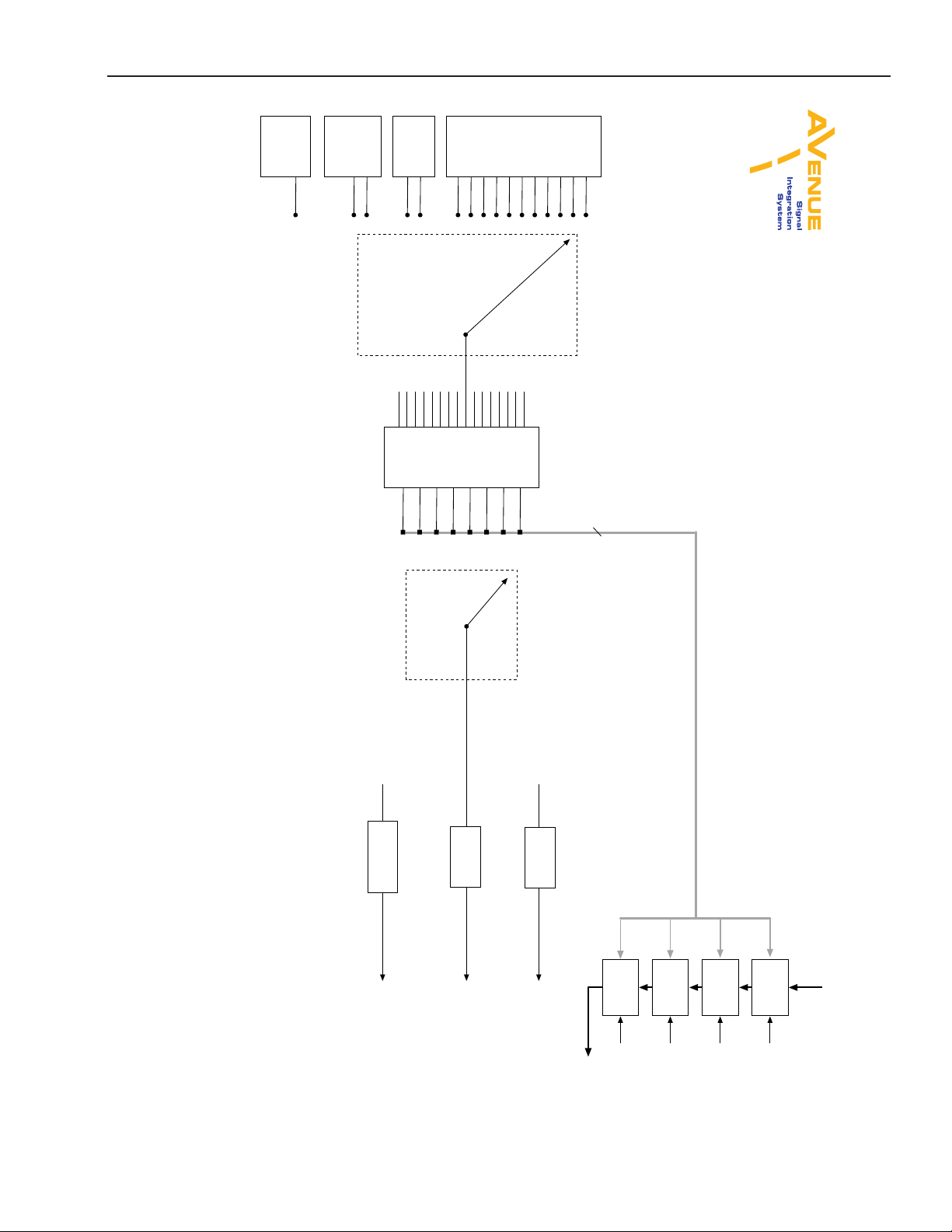
Functional Block Diagram, landscape view
www.ensembledesigns.com
Avenue 7400 and 9400 - Page 8
Page 9
Model 7400 HD/SD and Model 9400 3G/HD/SD Sync Pulse Generator and Test Signal Generator
Applications
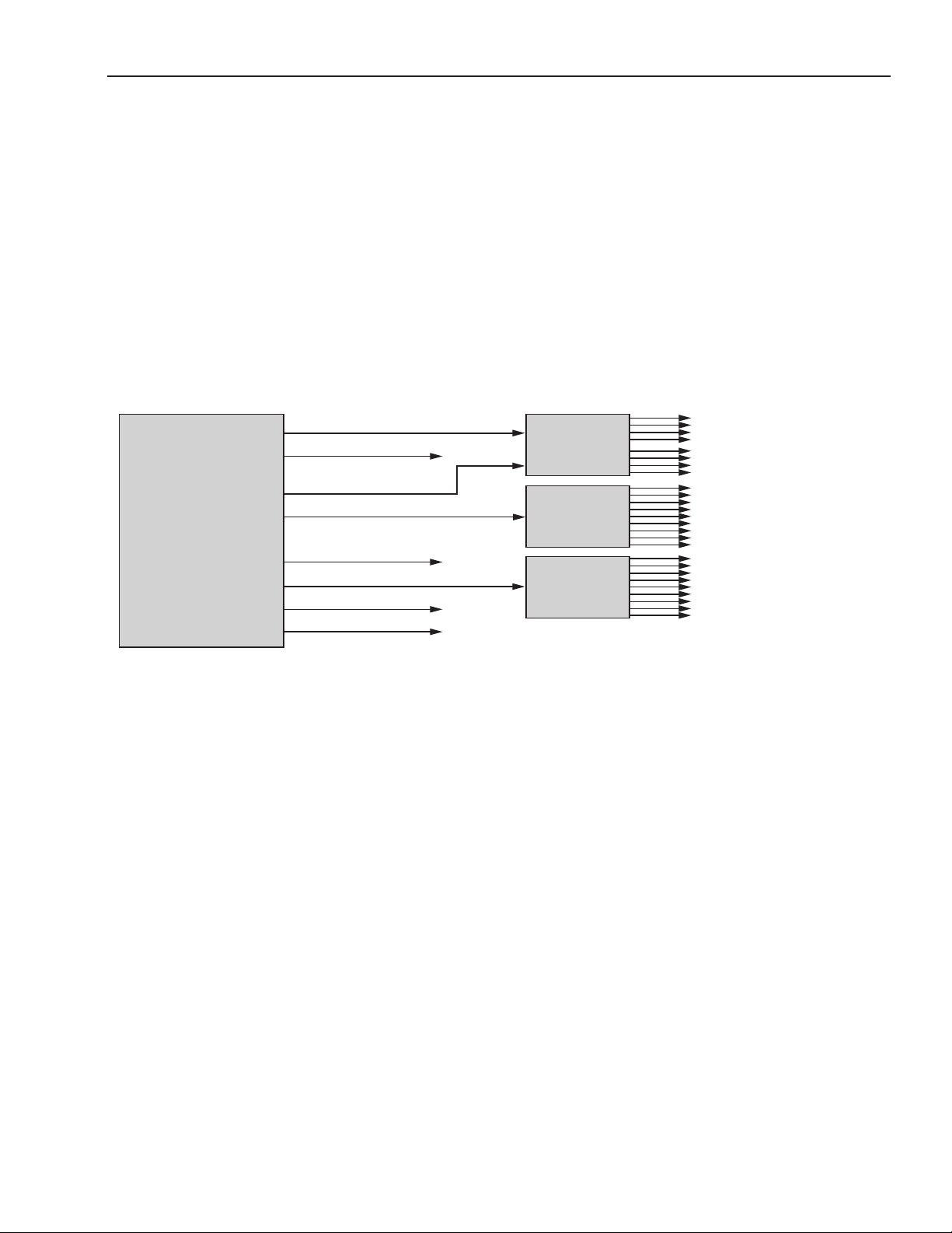
A Complete SPG and TSG System
The 7400 and 9400 can be combined with other Avenue modules to create a complete sync pulse
and test signal chain. The application shown below illustrates how the 9400 module provides digital,
analog and audio reference outputs which can be distributed throughout a facility when combined
with the 9125 Dual DA and the 5150 DA. The 5150 distribution amplier can be used to distribute
multiple copies of AES audio, Tri-Level Sync or composite black signals as needed. For distribution of
3G signals, the 9125 Dual DA is a good t.
9400
3G/HD/SD
SPG & TSG
3G, HD or SD SDI Test Signal
Composite or Tri-Level Sync
3G, HD or SD SDI Test Signal
Composite or Tri-Level Sync
Tri-Level Sync
AES 1/2
AES 3/4
Analog Audio
9125 DA
5150 DA
5150 DA
A Complete Sync Pulse and Test Signal Chain Example Using 9400
3G, HD or SD SDI (x4)
3G, HD or SD SDI (x4)
Composite or TLS (x9)
AES Reference (x9)
www.ensembledesigns.com
Avenue 7400 and 9400 - Page 9
Page 10
Model 7400 HD/SD and Model 9400 3G/HD/SD Sync Pulse Generator and Test Signal Generator
Broadcast
The Avenue 7400 and 9400 provide a comprehensive set of signals for TV stations. Analog sync, SD
bars and black, HD bars and black and audio reference are simultaneously available. You can even
output multiple kinds of Tri-Level Sync to support all of your HD equipment. Programmable outputs
allow you to select the signals you need for your station. An external AES source can be embedded
into your test patterns as well. Avenue sync changeover and redundant power options oer added
security.
7400 Broadcast Application
Conguration Example
7400 TSG
SDI B
Out 1B
Out 2B
Out 3B
SDI A
Out 1A
Out 2A
Out 3A
GPS Antenna
Genlock/
10 MHz In
Audio
SDI B
Out 1B
Out 2B
SD SDI bars to router, vision
mixer, production switcher
Analog sync to sync DAs,
servers, VTRs, etc.
HD SDI bars to router,
vision mixer, production switcher
1080i tri-level sync
720p tri-level sync
Analog tone to audio board
9400 TSG
SD SDI bars to router, vision
mixer, production switcher
Analog sync to sync DAs,
servers, VTRs, etc.
9400 Broadcast Application
Conguration Example
www.ensembledesigns.com
Out 3B
SDI A
Out 1A
Out 2A
Out 3A
GPS Antenna
Genlock/
10 MHz In
Audio
3 Gb/s or 1.5 Gb/s HD SDI bars to
router, vision mixer, production switcher
1080i tri-level sync
720p tri-level sync
Analog tone to audio board
Avenue 7400 and 9400 - Page 10
Page 11
Model 7400 HD/SD and Model 9400 3G/HD/SD Sync Pulse Generator and Test Signal Generator
Mobile Applications
All of the Avenue SPG/TSGs are rugged enough for use in mobile trucks, ENG and helicopters. The
Avenue frame has a retainer bar on it that ensures modules in the frame are completely stable. The
Avenue 7400 and 9400 have a wide range of test signals to choose from. Test patterns can have a
moving element so that you can be sure that a signal is not frozen in a frame sync somewhere in the
signal chain. Time code is available on BNC and 15 pin D for your convenience. The 7400 GPS option is
integrated nicely onto the main 7400 or 9400. The GPS antenna connects to a BNC on the 7400 or 9400
module providing precision timing accuracy along with timecode data and date and time insertion.
7400 Mobile Application
Conguration Example
7400 TSG
SDI B
Out 1B
Out 2B
Out 3B
SDI A
Out 1A
Out 2A
Out 3A
GPS Antenna
Genlock/
10 MHz In
Audio
9400 TSG
SDI B
Out 1B
Out 2B
HD SDI bars to vision
mixer, switcher
Analog sync to sync DAs,
cameras, VTRs, etc.
SD SDI bars to switcher
1080i tri-level sync
720p tri-level sync
VITC or LTC to time code
router and VTRs
3 Gb/s or 1.5 Gb/s HD SDI bars
to vision mixer, switcher
Analog sync to sync DAs,
cameras, VTRs, etc.
9400 Mobile Application
Conguration Example
www.ensembledesigns.com
Out 3B
SDI A
Out 1A
Out 2A
Out 3A
GPS Antenna
Genlock/
10 MHz In
Audio
SD SDI bars to switcher
1080i tri-level sync
720p tri-level sync
VITC or LTC to time code
router and VTRs
Avenue 7400 and 9400 - Page 11
Page 12
Model 7400 HD/SD and Model 9400 3G/HD/SD Sync Pulse Generator and Test Signal Generator
Post Production
Both Model 7400 and Model 9400 can output multiple formats of Tri-Level Sync at the same time,
tting the requirements of busy post production houses. At the same time, the 7400 or 9400 will
output HD-SDI test signals (1.5 Gb/s for the 7400, and 3 Gb/s and 1.5 Gb/s for the 9400), SD SDI and
composite test signals, and color black reference. All of these video outputs are derived from the same
time base and can be timed with respect to each other. Models 7400 and 9400 can simultaneously
deliver both 525 (NTSC) and 625 (PAL) based signals.
Models 7400 and 9400 provide extensive support for analog and digital audio. Because all of the video
outputs can be locked to a common time base, the AES digital audio outputs are always synchronous
with all of the video outputs - regardless of format. Multiple tone generators make it easy to identify
multi-channel content.
Multiple time code generators, another feature of the 7400 and 9400, work very well for post. Time
code is delivered as LTC (both 75 Ohm BNC and 110 Ohm Balanced), VITC, and DVITC. One generator
can be congured to produce 525/59.94 drop frame time code while the other generator is making
1080sF/23.98.
7400 TSG
SDI B
Out 1B
Out 2B
Out 3B
SDI A
Out 1A
Out 2A
Out 3A
GPS Antenna
Genlock/
10 MHz In
Audio
HD SDI black to router
625 color black
1080i 50 tri-level sync
1080p 50 tri-level sync
SD SDI black to router
720p 50 tri-level sync
Wordclock to audio rooms
7400 Post House Conguration Example
9400 TSG
SDI B
Out 1B
Out 2B
Out 3B
SDI A
Out 1A
Out 2A
Out 3A
GPS Antenna
Genlock/
10 MHz In
Audio
HD or 3G SDI black to router
625 color black
1080i 50 tri-level sync
1080p 50 tri-level sync
SD SDI black to router
720p 50 tri-level sync
Wordclock to audio rooms
9400 Post House Conguration Example
Custom Test Patterns
Using the Secure Digital Card slot on the front of the 7400 or 9400, users can load custom test patterns
and video slates into the module. With simultaneous audio and video playback, you can have branded
color bars available everywhere in the facility.
www.ensembledesigns.com
Avenue 7400 and 9400 - Page 12
Page 13

Model 7400 HD/SD and Model 9400 3G/HD/SD Sync Pulse Generator and Test Signal Generator
Timecode
How the Timecode is Generated
Each of the two (independent) SPG/TSGs on a 7400 or 9400 module has its own timecode generator.
The timecode generator will always run at the same frame rate as the SDI output of that SPG/TSG.
SDI Output TC Frame Rate VITC on SD Output Drop
720p/59.94 29.97 Frames/second* yes On or O
720p/50 25 Frames/second* yes N/A
1080i/59.94 29.97 Frames/second yes On or O
1080i/50 25 Frames/second yes N/A
1080sF/23.98 23.98 Frames/second no On or O
1080sF/24 24 Frames/second no N/A
SD 525 29.97 Frames/second yes On or O
SD 625 25 Frames/second yes N/A
*In these two cases, timecode identies pairs of video frames, with eld bit used to identify rst and
second frames of each pair. This is because the legacy SMPTE 12M specication cannot accommodate
frame rates larger than 39Hz.
The user can “Jam” a specic time setting into the timecode generator. If the GPS option is installed, the
Timecode generator can be commanded to pick up current time of day. The Timecode generator can
be congured for drop or non-drop operation when running in the NTSC related frame rates.
Analog Timecode
There are four ways to have analog timecode, described as follows:
1. Route LTC (linear timecode) to user-programmable BNC 2 or 3. The signal will be 1 V P-P,
unbalanced (i.e., single ended). This is an analog timecode signal. Many devices want timecode on
a BNC.
2. Select LTC to appear as one of the module's analog audio output signals. This will be exactly the
same signal as when it is routed to a BNC, but it will be a balanced analog signal. It would appear
on the HD-15 connector as one of the four balanced audio outputs.
3. LTC can be selected as one of the audio signals to be embedded in the SDI output stream.
4. LTC can be selected as one of the audio signals to be output as AES on User Pgm Outputs 2 or 3.
You can output an analog timecode signal with any of the methods described above. The dierence
between them is a choice between balanced or unbalanced. If you need to feed timecode to a device
with an XLR input, you would generally want to use the balanced output. However, it is also possible
to use the unbalanced through user-programmable BNC output and connect it to the destination with
a balancing transformer. This would be much like the DATS adaptors for AES.
The advantage of using the unbalanced BNC output is that you can run it through a 5150 Distribution
Amplier to make more copies.
www.ensembledesigns.com
Avenue 7400 and 9400 - Page 13
Page 14

Model 7400 HD/SD and Model 9400 3G/HD/SD Sync Pulse Generator and Test Signal Generator
Vertical Interval Timecode (VITC) and Digital Vertical Interval Timecode (DVITC)
The 7400 and 9400 oer the following ways to have Vertical Interval Timecode (VITC) and Digital
Vertical Interval Timecode (DVITC):
1. The Analog Composite output of each generator (User-Programmable Output 1) can have VITC
carried in the vertical interval.
2. When the SDI output is standard denition, it can have VITC in the vertical interval. This is basically
a digitized version of the VITC that would be in an analog composite signal.
3. When the SDI output is high denition, it can have DVITC packets carried in the ancillary data
spaces.
4. When a 7400 GPS option is installed, VITC and DVITC are available from the GPS.
Locking to a Black Burst Signal with VITC
Models 7400 and 9400 can lock to a black burst signal which has VITC in it. In that case, the timecode
generator in the 7400 or 9400 will track that VITC reference.
www.ensembledesigns.com
Avenue 7400 and 9400 - Page 14
Page 15
Model 7400 HD/SD and Model 9400 3G/HD/SD Sync Pulse Generator and Test Signal Generator
Audio Generation and Routing
Audio Generators
The diagram shown below depicts the audio signal generation and routing for a single SPG/TSG
Generator. There are two generators on each 7400 or 9400, Generator A and Generator B. Each of the
two generators on the module are identical, with completely independent controls.
Support for Analog and Digital Audio
The AES digital audio outputs are always synchronous with all of the video outputs – regardless
of format – because all of the video outputs can be locked to a common time base. Multiple tone
generators can be used to identify multi-channel content.
Sixteen Independently Programmable Audio Channels Per Generator
Each generator supports sixteen audio channels and the content of each channel is independently
programmable. Choices include adjustable frequency tone generators, tone sweeps, silence, timecode,
audio clip playback from the 7400 or 9400’s secure digital card, and the external AES input. Left/Right
channel ID that synchronizes to the cyclops feature can also be selected.
Audio Embedded in the SDI Outputs
All sixteen of these channels can be embedded in the SDI outputs. Each AES output can select from
any of the eight pairs that make up these sixteen channels. Similarly, the stereo analog output of each
generator can be driven from any of these audio signal pairs.
TM
7400/9400 SPG/TSG
Audio Generation
and Routing
This drawing depicts the Audio Signal Generation and routing for
a single SPG/TSG Generator. Each of the two generators on the 7400
and 9400 are identical, with completely independent controls.
300 Hz
400 Hz
500 Hz
600 Hz
800 Hz
Tone
1.0 KHz
Generator
1.2 KHz
1.6 KHz
Silence
TSG Audio
Timecode
Left/Ch 1
DDR2
Audio
Right/Ch 2
Playback
Left/Ch 1
External
AES
Right/Ch 2
Input
WorkClock
Aligned
Shaped LTC
from
Timecode
Generator
Note: DDR2 and AES sources could be
constrained to a single choice, where Left
would always map to an odd channel,
and right to an even channel
LTC
Channel Source Selector
typical of 16 places
Channel
Pairing
8 Channel Pairs
Ch 1/2
Ch 3/4
Ch 5/6
Ch 7/8
Ch 9/10
Ch 11/12
Ch 13/14
Ch 15/16
Note: Explicit source of Silence provides ability
to deliver AES Silence (DARS) on output BNCs
without requiring a silent pair in the embedded service.
Audio Pair Selector
typical of 3places
AES
Encoder
AES
Encoder
Analog Audio
Output Trim
Video from TSG
Group 1
Embedder
Ch 1:4
Group 2
Embedder
Ch 5:8
Group 3
Embedder
Ch 9:12
Group 4
Embedder
Ch 13:16
To User Out 2 Source Selector
To User Out 3 Source Selector
To Analog Output Port
Enable
Enable
Enable
Enable
To Serializer
7400 and 9400 Audio Generation and Routing Diagram, portrait view
www.ensembledesigns.com
Avenue 7400 and 9400 - Page 15
Page 16
Model 7400 HD/SD and Model 9400 3G/HD/SD Sync Pulse Generator and Test Signal Generator
This drawing depicts the Audio Signal Generation and routing for
a single SPG/TSG Generator. Each of the two generators on the 7400
Generator
Timecode
Note: DDR2 and AES sources could be
constrained to a single choice, where Left
would always map to an odd channel,
and right to an even channel
Shaped LTC
WorkClock
Input
Aligned
from
LTC
External
AES
Left/Ch 1
Right/Ch 2
Channel Source Selector
typical of 16 places
Playback
Audio
DDR2
Left/Ch 1
Right/Ch 2
Timecode
Silence
TSG Audio
1.2 KHz
1.6 KHz
Generator
Tone
800 Hz
1.0 KHz
600 Hz
500 Hz
400 Hz
300 Hz
and 9400 are identical, with completely independent controls.
and Routing
7400 and 9400 Audio Generation and Routing Diagram, landscape view
Channel
Pairing
Ch 1/2
Ch 3/4
Ch 5/6
Ch 7/8
Ch 9/10
Ch 11/12
Ch 13/14
Ch 15/16
Note: Explicit source of Silence provides ability
to deliver AES Silence (DARS) on output BNCs
without requiring a silent pair in the embedded service.
8 Channel Pairs
TM
7400/9400 SPG/TSG
Audio Generation
Audio Pair Selector
typical of 3places
Analog Audio
Output Trim
To Analog Output Port
Encoder
AES
To User Out 3 Source Selector
Encoder
AES
To User Out 2 Source Selector
Embedder
Ch 13:16
Enable
To Serializer
Embedder
Group 4
Ch 9:12
Enable
Embedder
Group 3
Ch 5:8
Enable
Embedder
Ch 1:4
Enable
Group 1
Group 2
Video from TSG
www.ensembledesigns.com
Avenue 7400 and 9400 - Page 16
Page 17
Model 7400 HD/SD and Model 9400 3G/HD/SD Sync Pulse Generator and Test Signal Generator
Installation
Plug the 7400 or 9400 module into any one of the slots in the 3RU frame. In a 1RU frame, 7400 and
9400 modules can be installed in slots 1 or 2, and not in slot 3. Install the plastic overlay provided
onto the corresponding group of rear BNC connectors associated with the module location. Note that
the plastic overlay has an optional adhesive backing for securing it to the frame. Use of the adhesive
backing is only necessary if you would like the location to be permanent and is not recommended
if you need to change module locations. This module may be hot-swapped (inserted or removed)
without powering down or disturbing performance of the other modules in the system.
7400-GPS Option Field Installation Procedure
The 7400-GPS Option seamlessly integrates into the Avenue system by plugging directly onto a 7400
or 9400 module. It can be easily installed in the eld. The 7400-GPS Option consists of a compact,
weatherproof antenna (with internal high-gain pre-amp) and a receiver submodule which mounts
directly to the 7400 or 9400 module. The included GPS antenna mounts onto standard 3/4” threaded
pipe, metal or plastic. Connection from the F-style coaxial tting on the antenna to the appropriate
BNC on the Avenue Frame can be made with customer supplied standard 75 ohm cable. The coax
cable can be routed through the center of the pipe for a completely waterproof installation. When low
loss cable such as Belden 1694A is used, the antenna can be placed up to 200 feet (60 meters) from the
frame. Ideally, the antenna is mounted outdoors where it has an unobstructed view of the sky.
If you order the 7400-GPS Option and Model 7400 or 9400 at the same time, we will install the
7400-GPS Option on to the main module at the factory. If you order the 7400-GPS Option and already
have Model 7400 or 9400, you will receive the following kit.
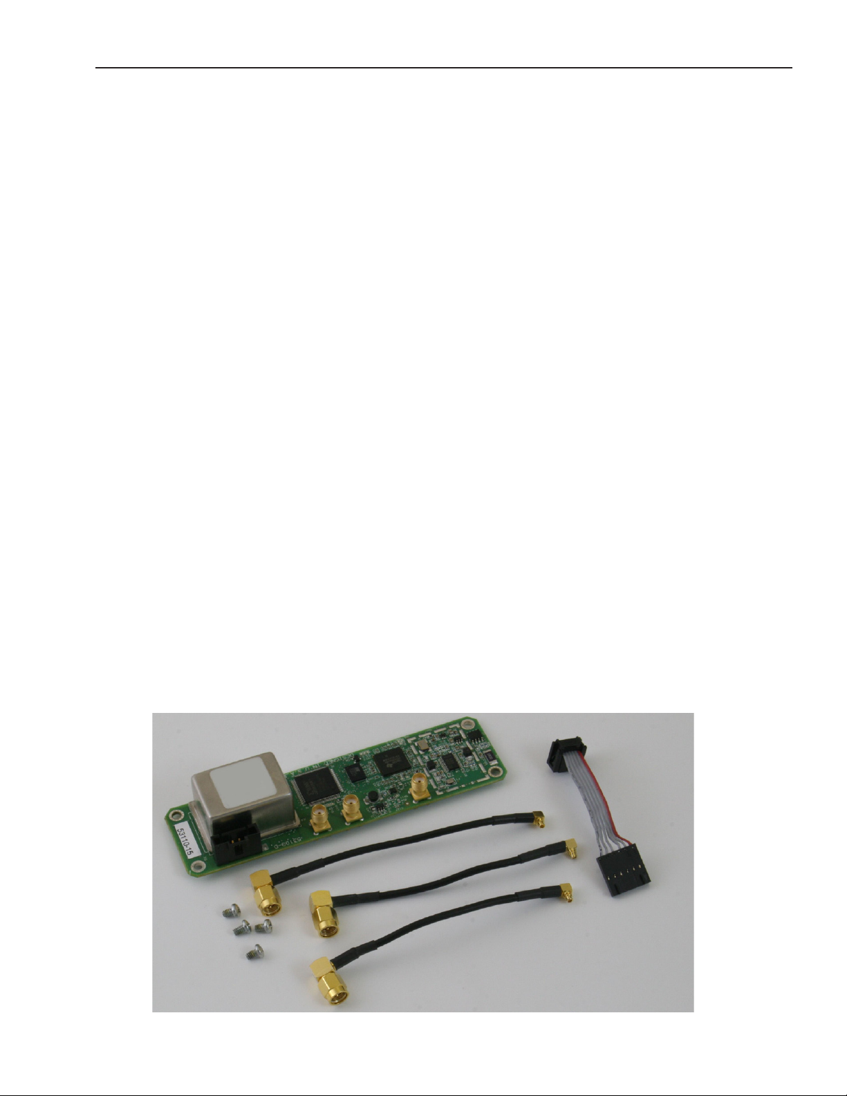
7400-GPS Option Kit
The 7400-GPS Option consists of the following components, see photograph below:
• GPSOptionsubmodule •PowerandControlcable
• Threecoaxialjumpercables •FourPhillipsmachinescrews
• GPS Compact Weatherproof Antenna with internal high-gain pre-amp (not shown in photo)
www.ensembledesigns.com
Avenue 7400 and 9400 - Page 17
Page 18
Model 7400 HD/SD and Model 9400 3G/HD/SD Sync Pulse Generator and Test Signal Generator
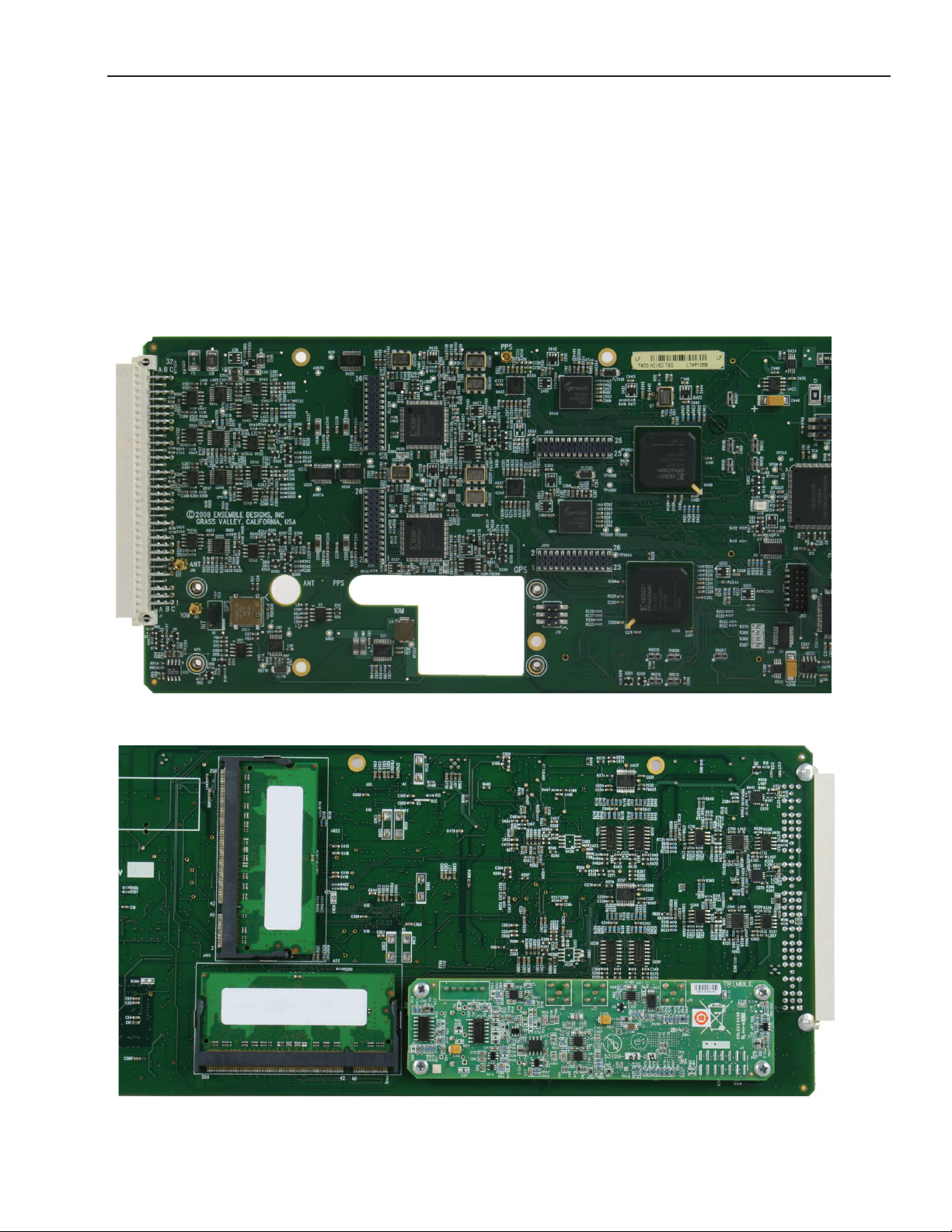
Securing the 7400-GPS Option Submodule to the 7400 or 9400 Main Module
Mount the 7400-GPS Option submodule onto the backside of the 7400 or 9400 main module and
secure it using the four Phillips machine screws provided in your kit.
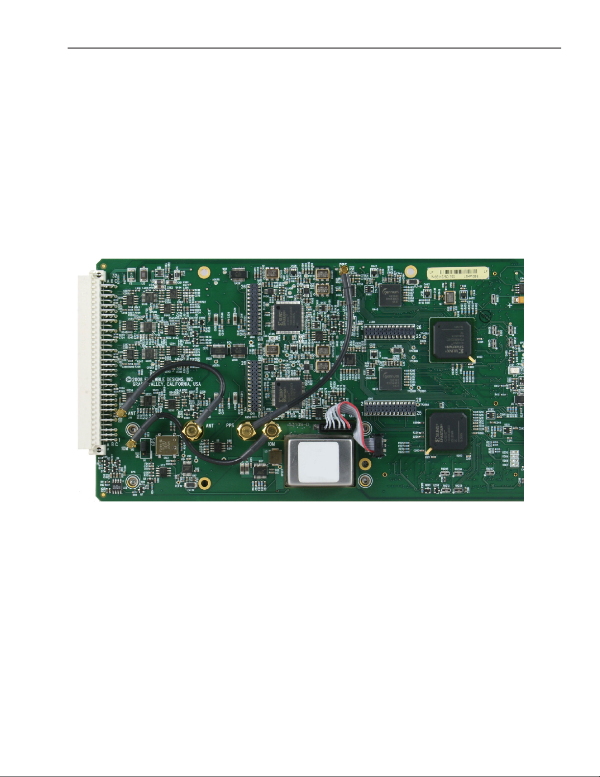
The rst photo below shows the 7400 or 9400 main module prior to installing the optional
7400-GPS Option submodule. This is a topside view. Note the large hole in the module that the
7400-GPS Option submodule protrudes through when installed.
The second photo shows the bottom side of the 7400 or 9400 main module with the 7400-GPS Option
submodule installed and retained with the four machine screws.
7400 or 9400 module prior to 7400-GPS Option installation, top side view
7400 or 9400 module with 7400-GPS Option installed, bottom side view
www.ensembledesigns.com
Avenue 7400 and 9400 - Page 18
Page 19
Model 7400 HD/SD and Model 9400 3G/HD/SD Sync Pulse Generator and Test Signal Generator
Connecting the Cables between the 7400-GPS Option Submodule and the 7400 or 9400 Main Module
Connect the three coaxial cables as shown in the photo below. Note that for each of these cables the
main module and the submodule have matching labels:
• 10M submodule connects to 10M main module
• ANT submodule connects to ANT main module
• PPS submodule connects to PPS main module
Connect the power/control cable as shown in the photo below. Note how the ribbon cable connects,
and the orientation of the red band which indicates pin 1.
www.ensembledesigns.com
7400-GPS Option cabling detail
Avenue 7400 and 9400 - Page 19
Page 20
Model 7400 HD/SD and Model 9400 3G/HD/SD Sync Pulse Generator and Test Signal Generator
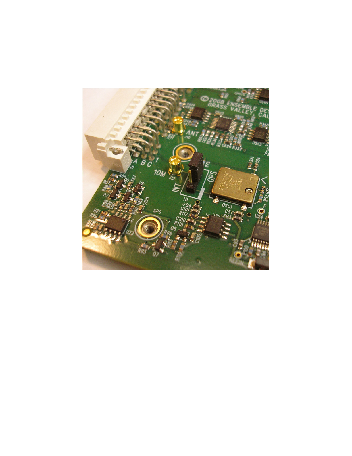
H1 Jumper Positioning
When eld installing the 7400-GPS Option, move the H1 jumper to the GPS position, as shown in
the photo below, to lock to the GPS reference signal. 7400 and 9400 modules ship from the factory
with the H1 jumper installed in the INT position, locking to the 7400’s internal TCXO (Temperature
Compensated Crystal Oscillator).
www.ensembledesigns.com
Avenue 7400 and 9400 - Page 20
Page 21
Model 7400 HD/SD and Model 9400 3G/HD/SD Sync Pulse Generator and Test Signal Generator
Installing the GPS Antenna
The included GPS antenna is compact, weatherproof, and has internal high-gain pre-amplication.
It mounts onto standard 3/4” threaded pipe, metal or plastic. Connection from the F-style coaxial
tting on the antenna to the appropriate BNC on the Avenue Frame can be made with customer
supplied standard 75 ohm cable. The coax cable can be routed through the center of the pipe for a
completely waterproof installation. When low loss cable such as Belden 1694A is used, the antenna
can be placed up to 200 feet (60 meters) from the frame. Ideally, the antenna is mounted outdoors
where it has an unobstructed view of the sky.
Even if you do not connect the GPS Antenna to the 7400-GPS module, it will nevertheless provide
greater accuracy than the module’s internal TCXO (Temperature Compensated Crystal Oscillator).
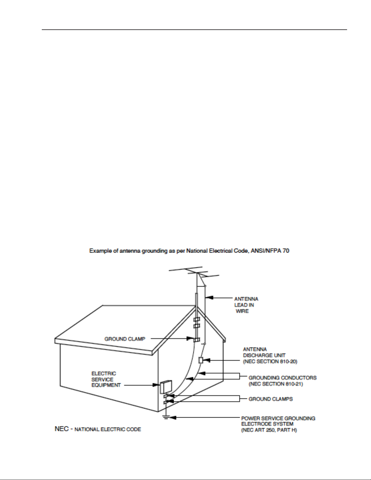
Safety and Outdoor Antenna Grounding
When installing the antenna for the 7400-GPS option, please be aware of safety precautions with
respect to outdoor antenna grounding. Please read the following excerpt from the National
Electric Code and refer to the below illustration.
“If an outside antenna or cable system is connected to the product, be sure the
antenna or cable system is grounded so as to provide some protection against
voltage surges and built-up static charges. Article 810 of the National Electrical
Code, ANSI/NFPA 70, provides information with regard to proper grounding of
the mast and supporting structure, grounding of the lead-in wire to an antenna
discharge unit, size of grounding conductors, location of antenna-discharge
unit, connection to grounding electrodes, and requirements for the grounding
electrode.”
www.ensembledesigns.com
Avenue 7400 and 9400 - Page 21
Page 22
Model 7400 HD/SD and Model 9400 3G/HD/SD Sync Pulse Generator and Test Signal Generator
SD test pattern, this BNC can
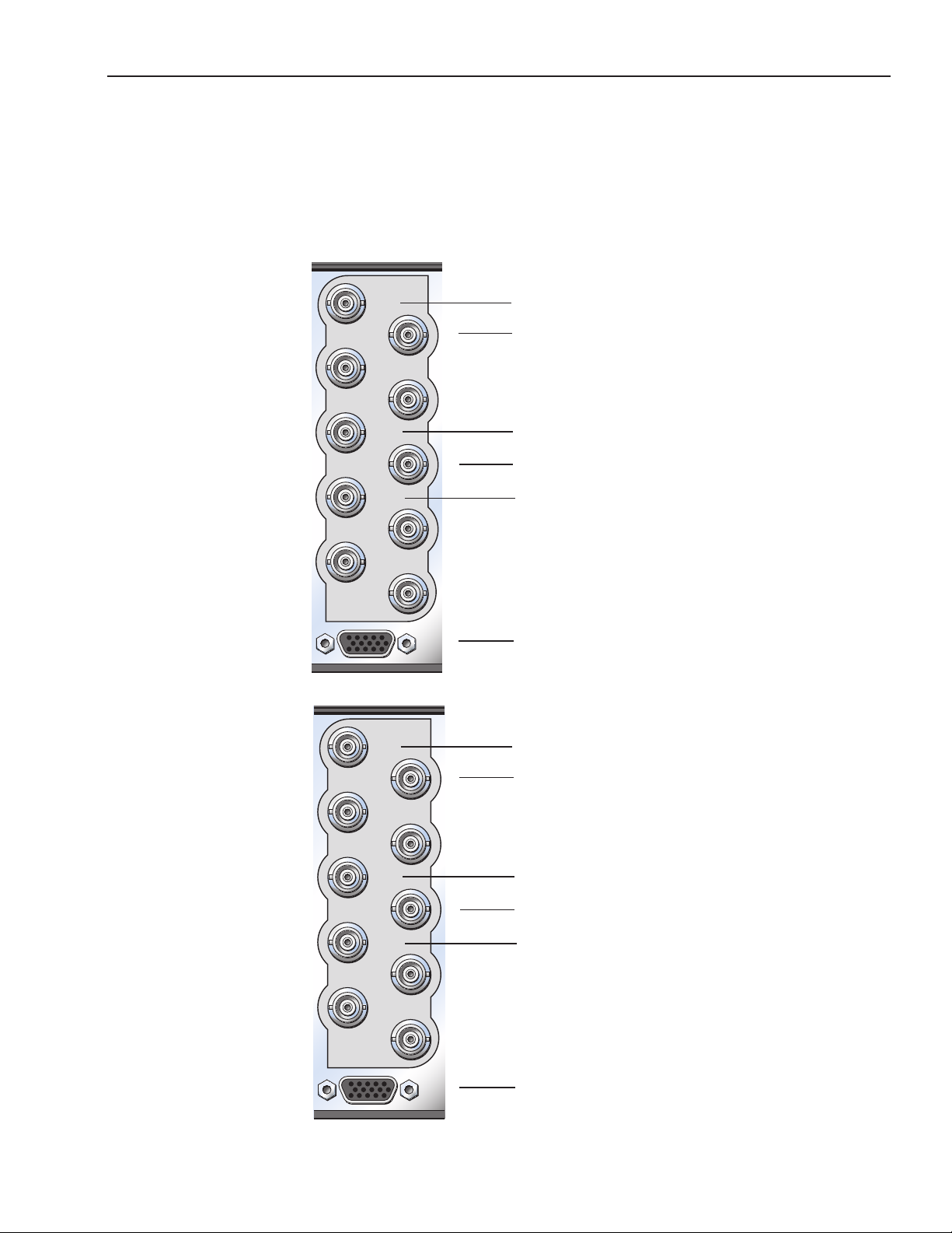
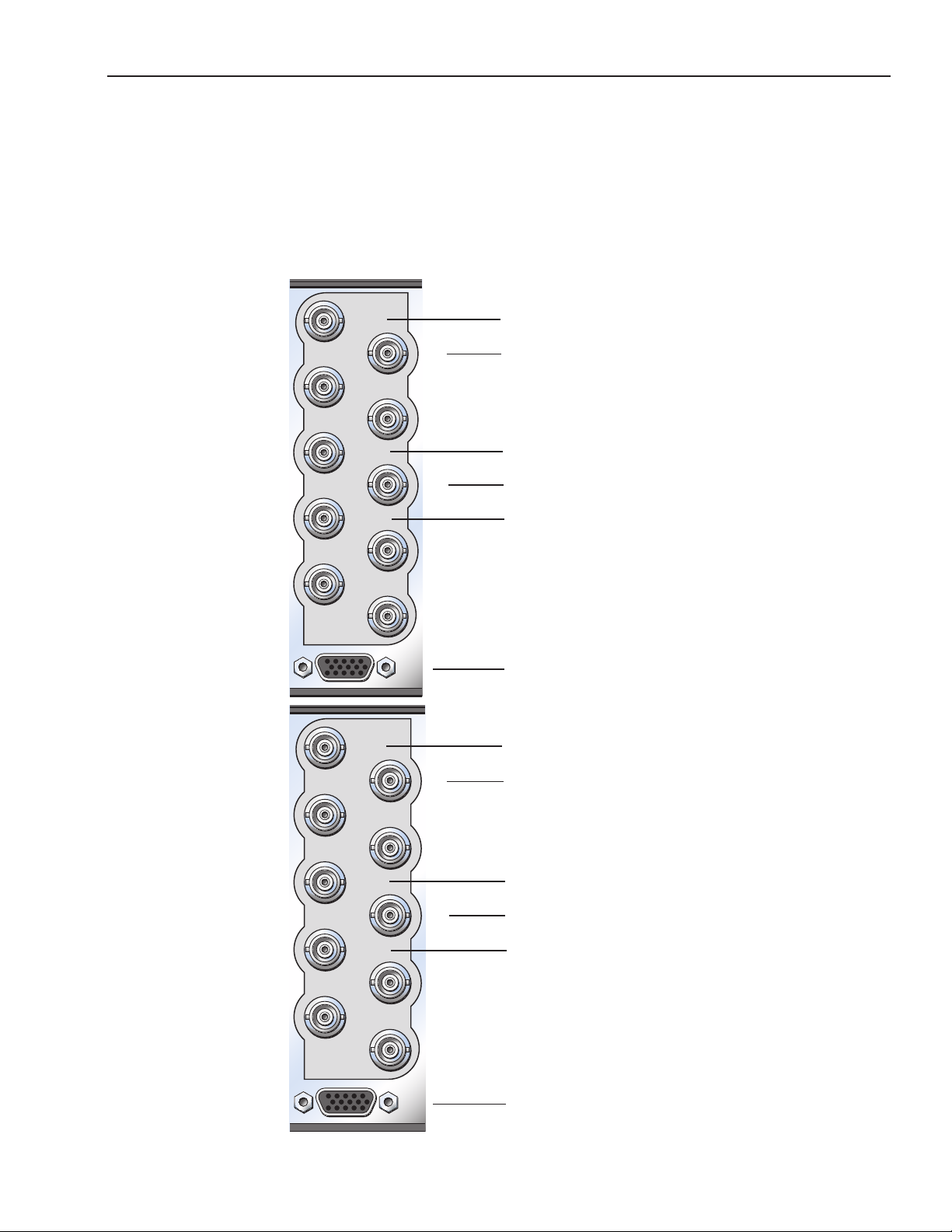
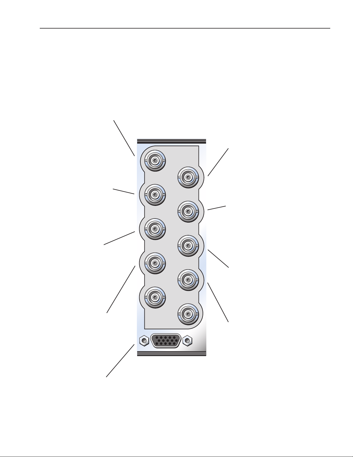
Cabling
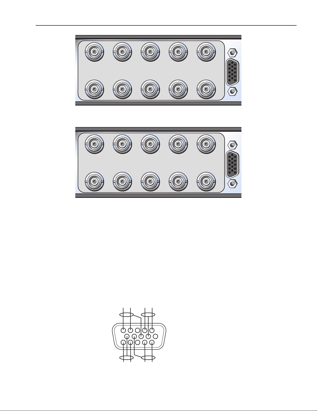
Refer to the 3RU and 1RU backplane diagrams of the module below for cabling instructions. Note that
unless stated otherwise, the 1RU cabling explanations are identical to those given in the 3RU diagram.
Outputs HD or SD
test signals
(plus 3G for 9400).
Select frame rate family
for all of Generator B;
59.94, 50 or 60. Output
can include 16 channels
of embedded audio –
tone, silence or external
audio. Can also include
DVITC.
Outputs one of the
following: Tri-Level Sync
from TLS Gen 2 (can be
different from Out 1 B)
LTC, AES (any of 8 pairs),
AES silence, Word clock,
6 Hz pulse, 10 MHz (only
if locked to internal or
GPS reference).
Outputs HD or SD
test signals
(plus 3G for 9400).
Select frame rate family
for all of Generator A;
59.94, 50 or 60. Output
can include 16 channels
of embedded audio –
tone, silence or external
audio. Can also include
DVITC.
Outputs one of the
following: Tri-Level Sync
from TLS Gen 2 (can be
different from Out 1 A)
LTC, AES (any of 8 pairs),
AES silence, Word clock,
6 Hz pulse, 10 MHz (only
if locked to internal or
GPS reference).
Stereo audio output.
7400 TSG
SDI B
Out 1B
Out 2B
Out 3B
SDI A
Out 1A
Out 2A
Out 3A
GPS Antenna
Genlock/
10 MHz In
Audio
Outputs analog composite
black, composite 100% bars,
or Tri-Level Sync from TLS
Gen 1. When SDI Out B is a
SD test pattern, this BNC can
also output a composite
version of that test pattern.
Composite output can
include VITC.
Outputs one of the
following: Tri-Level Sync
from TLS Gen 2 (same as
Out 2 B), LTC, AES (any of
8 pairs), AES silence,
Word clock, 6 Hz pulse,
10 MHz (only if locked to
internal or GPS reference).
Outputs analog composite
black, composite 100% bars,
or Tri-Level Sync from TLS
Gen 1. When SDI Out A is a
also output a composite
version of that test pattern.
Composite output can
include VITC.
Outputs one of the
following: Tri-Level Sync
from TLS Gen 2 (same as
Out 2 A), LTC, AES (any of
8 pairs), AES silence,
Word clock, 6 Hz pulse,
10 MHz (only if locked to
internal or GPS reference).
www.ensembledesigns.com
3RU Backplane for 7400
Avenue 7400 and 9400 - Page 22
Page 23
Model 7400 HD/SD and Model 9400 3G/HD/SD Sync Pulse Generator and Test Signal Generator
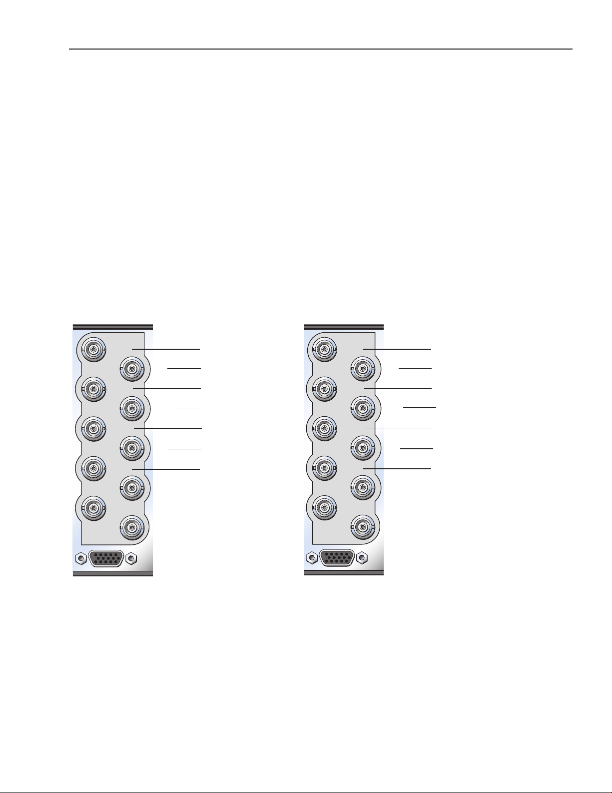
7400 TSG
9400 TSG
Out 1AOut 3BOut 1B
SDI A
Out 3A
Out 2AOut 2BSDI B
1RU Backplane for 7400
Out 1AOut 3BOut 1B
SDI A
Out 3A
Out 2AOut 2BSDI B
1RU Backplane for 9400
Genlock/
10 MHz In
GPS Ant.
Genlock/
10 MHz In
GPS Ant.
Audio
Audio
You can access four mono channels of audio analog tone outputs as shown in the pinout below.
Channels 1 and 2 come from Audio Generator A; Channels 3 and 4 come from Audio Generator B.
Channels 1 through 4 can be assigned to any of the 16 channels of audio from the Aud Gen A/B menu
pages.
AUD 1 is on pins 1 and 2 and the associated ground is pin 7. Pin 1 is positive. AUD 2 is on pins 4 and 5
and the associated ground is pin 8. Pin 5 is positive.
AUD 3 is on pins 11 and 12 and the associated ground is pin 9. Pin 11 is positive. AUD 4 is on pins 14
and 15 and the associated ground is pin 10. Pin 15 is positive.
-
-
AUD 1
-
-
AUD 3
+
Generator A
1
6
11
Generator B
+
AUD 2
+
+
AUD 4
www.ensembledesigns.com
Avenue 7400 and 9400 - Page 23
Page 24

Model 7400 HD/SD and Model 9400 3G/HD/SD Sync Pulse Generator and Test Signal Generator
Generator A
• SDI Out A – Outputs HD or SD test signals (plus 3G for 9400). Select frame rate family for all
of Generator A; 59.94, 50 or 60. Output can include 16 channels of embedded audio. The
embedded audio can be any combination of the following: tone, silence, external audio. Can
also include DVITC.
• Programmable Out 1 A – Outputs analog composite black, composite 100% bars, or
Tri-Level Sync from TLS Gen 1. When SDI Out A is a SD test pattern, this BNC can also output a
composite version of that test pattern. Composite output can include VITC.
• Programmable Out 2 A – Outputs one of the following: Tri-Level Sync from TLS Gen 2 (can be
dierent from Out 1 A), LTC, AES (any of 8 pairs), AES silence, Word clock, 6 Hz pulse, 10 MHz
(only if locked to internal or GPS reference).
• Programmable Out 3 A – Outputs one of the following: Tri-Level Sync from TLS Gen 2 (same
as Out 2 A), LTC, AES (any of 8 pairs), AES silence, Word clock, 6 Hz pulse,10 MHz (only if locked
to internal or GPS reference).
Note: Generator A has two independent Tri-Level Sync generators; TLS Gen 1 and TLS
Gen 2. The output from TLS Gen 1 is available on BNC Out 1 A. The output from TLS Gen 2
is available on BNC’s Out 2 A and Out 3 A. Refer to the “Functional Block Diagram” on
page 8 for more information.
• Analog Audio - stereo output, 1 of 8 pairs from the audio generator.
Generator B
Has the same outputs as noted for Generator A. Generator B is completely independent from
Generator A. Generator B can operate in a dierent frame rate family and its set of outputs can be
timed independently.
www.ensembledesigns.com
Avenue 7400 and 9400 - Page 24
Page 25
Model 7400 HD/SD and Model 9400 3G/HD/SD Sync Pulse Generator and Test Signal Generator
Module Conguration and Control
Avenue module parameters can be congured and controlled remotely from one or both of the
remote control options: the Avenue Touch Screen or the Avenue PC Application. Once the module
parameters have been set remotely, the information is stored on the module CPU. This allows
the module be moved to a dierent slot in the frame at your discretion without losing the stored
information.
Details for setting module parameters remotely using the Avenue PC option or the Avenue Touch
Screen option are described and illustrated in the “Avenue PC and Touch Screen Remote Conguration”
section of this manual.
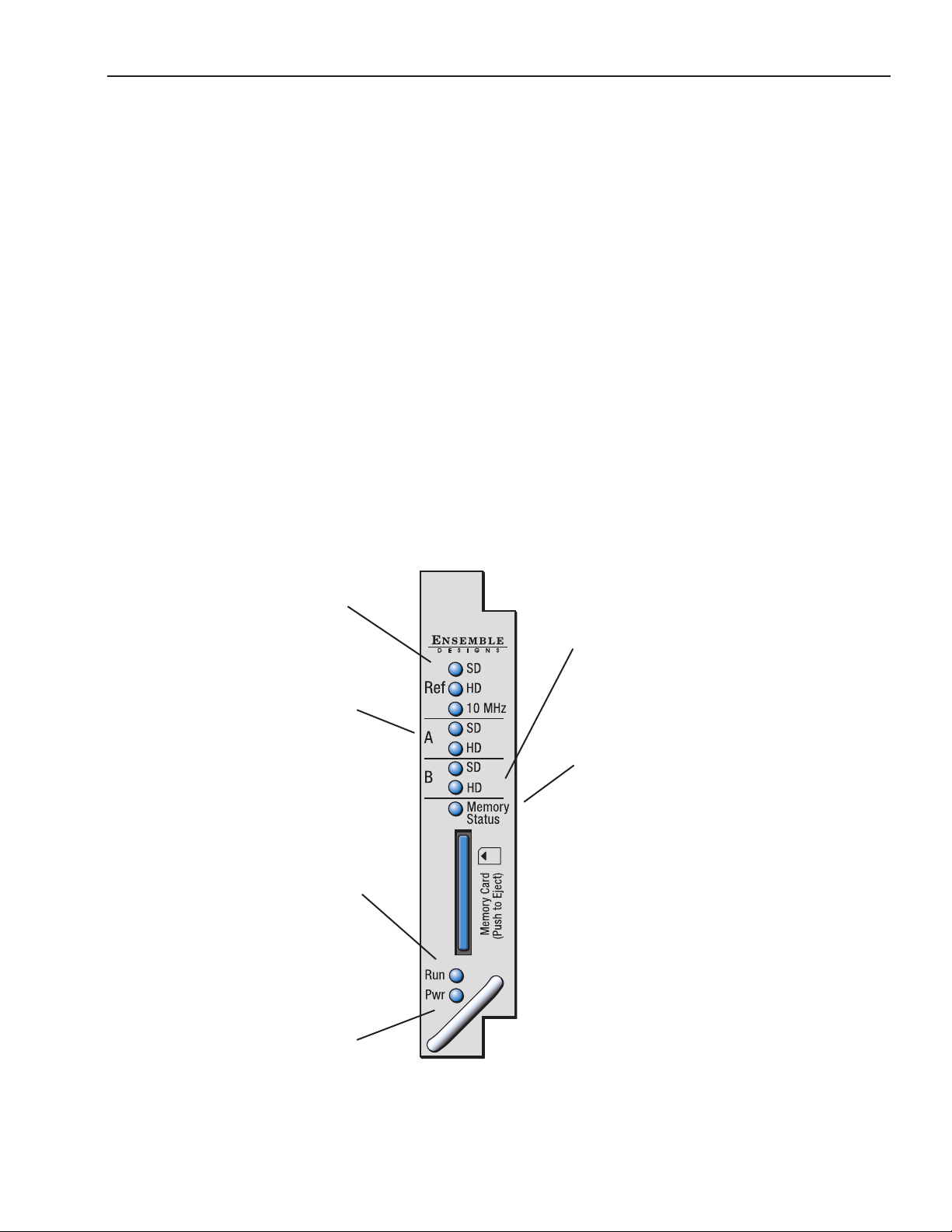
Front Panel Controls and Indicators
Each front edge indicator is shown in the diagram below:
Ref SD, HD and 10 MHz
green LEDs:
One LED will light to indicate
which type of reference is
currently being detected.
If no LED is lit, no reference is
detected.
Generator A SD/HD
green LEDs:
One LED will light to indicate the
Primary output standard and that
it is locked to its timing source.
If no LED is lit, the Primary
generator is not locked to its
timing source.
Run green LED:
OFF: A power fault or halted CPU
ON: A halted CPU
FAST BLINK: CPU Run error
SLOW BLINK: System OK (If SPI
control is active from the main
frame System Control Module, all
module Run indicators will be
synchronized.)
7400
HD/SD
Dual
SPG/TSG
Generator B SD/HD
green LEDs:
One LED will light to indicate the
Primary output standard and that
it is locked to its timing source.
If no LED is lit, the Primary
generator is not locked to its
timing source.
Memory Status green LED:
LED flashes when memory is
being accessed. Illuminates green
when memory is available.
Pwr green LED:
Indicates the presence (ON) or
absence (OFF) of power (+5V).
www.ensembledesigns.com
Avenue 7400 and 9400 - Page 25
Page 26

Model 7400 HD/SD and Model 9400 3G/HD/SD Sync Pulse Generator and Test Signal Generator
Avenue PC and Touch Screen Remote Conguration
The Avenue PC and Touch Screen remote control menus for this module are illustrated and explained
in this section. Refer to each menu’s description in the following pages for a summary of available
parameters that can be set remotely through the menus illustrated. Both the Avenue PC and Touch
Screen user interfaces are shown for your reference. For more information on using Avenue PC, refer to
the Avenue PC Control Application Software manual.
Parameter elds that are grayed out can indicate one of the following conditions:
• An option is not installed.
• The function is not active.
• The module is locked.
• The User Level set with Avenue PC does not permit access.
www.ensembledesigns.com
Avenue 7400 and 9400 - Page 26
Page 27

Model 7400 HD/SD and Model 9400 3G/HD/SD Sync Pulse Generator and Test Signal Generator
7400 and 9400 Avenue PC and Touch Screen Menus
Sync Pulse Generator A Menu
Selecting the Reference Source and Output Standard for Sync Pulse Generator A
The SPG A menu controls the SDI Out A BNC. The standard selected determines what signal will be
output on the SDI Out A BNC.
Important: Additionally, the standard selected in the SPG A menu determines the frame rate family
for all of the Generator A BNC outputs (SDI Out A, Out 1 A, Out 2 A, Out 3 A). For example, if the
standard is set to SD 525 or 720p/59.94, then all Generator A outputs will be in the 59.94 Hz frame
rate family. If the standard is set to SD 625 or 1080i/50, then all Generator A outputs will be in the
50 Hz frame rate family.
To select the reference source and output standard of Sync Pulse Generator A, select the SPG A
menu shown below. Set the parameters for the Source and Standard elds. The standard that the
module is locked to is shown in the Sync Lock eld. Use the controls to set the following:
• Source – select the reference source for Generator A. Select from:
Internal/GPS – the module’s Internal Precision Standard reference signal, or the signal from
the GPS Receiver (with 7400-GPS Option installed). If the GPS signal is present, the 7400 will
lock to that. If the GPS signal is not present, the 7400 will lock to its internal TCXO.
Cong Ref – locks to the source selected as the Cong Ref in the Global menu. If you
choose Cong Ref, you must have congured that parameter in the Global menu.
See the “Global Menu” on page 61 for more information.
Other Gen – locks to the reference of Generator B.
• Sync Lock – reports what standard the module is locked to.
Note: If you are using the 7400-GPS option, be sure the H1 jumper on the main module is
installed in the GPS position to lock to the GPS reference signal. If the H1 jumper is installed
in the INT position it locks to the 7400 or 9400’s internal TCXO (Temperature Compensated
Crystal Oscillator). See the “7400-GPS Option Field Installation Procedure” on page 17 for more
information.
• Standard – select the output standard you want from the following:
720p/50 1080p/23.98
720p/59.94 1080p/24
720p/60 1080sF/25
1080i/50 1080sF/23.98
1080i/59.94 1080sF/24
1080i/60 SD 525
1080p/25 SD 625
www.ensembledesigns.com
Avenue 7400 and 9400 - Page 27
Page 28

Model 7400 HD/SD and Model 9400 3G/HD/SD Sync Pulse Generator and Test Signal Generator
SPG A Avenue PC Menu
www.ensembledesigns.com
SPG A Touch Screen Menu
Avenue 7400 and 9400 - Page 28
Page 29

Model 7400 HD/SD and Model 9400 3G/HD/SD Sync Pulse Generator and Test Signal Generator
Test Signal Generator A Menu
Selecting the Pattern Type, Output Standard and Y, Cr and Cb Channels for Test Signal
Generator A
The TSG A menu aects the SDI Out A BNC. It also aects the Out 1 A BNC if it has been set to “Follow
SDI.”
To set the type of test pattern for the output of Test Signal Generator A, select the TSG A menu
shown below. This menu also has controls for turning on and o the Y, Cr and Cb channels.
Use the controls to set the following:
• Pattern Type – Select the pattern group in the rst drop-down menu and the test signal in the
second drop-down menu.
Pattern Group Test Signal
Bars Full Field 75
Full Field 100
SMPTE 75
Split Field 75
Split Field 100
Red Field
RGB444 Bars A
RGB444 Bars B
Black Black
Flat Field 20
Flat Field 50
Flat Field 80
White
RGB444 Black
Ramp Video Ramp
Data Ramp
Shallow
5 Step
Sweep Sweep
MultiBurst
Pulse & Bar Full Field Window
Component
Timing Digital Blanking
Cosite
Interlace
Misc Black
Crosshatch
Safe Title
Pathological
Card Custom Test Patterns from Secure Digital Card
www.ensembledesigns.com
Avenue 7400 and 9400 - Page 29
Page 30

Model 7400 HD/SD and Model 9400 3G/HD/SD Sync Pulse Generator and Test Signal Generator
• Y Channel, Cr Channel, Cb Channel checkboxes – There are independent enables for each
channel so that Y, Cr and Cb can be controlled separately. You may choose to turn o the Y, Cr
and/or Cb Channels if desired for test purposes (such as setting up a monitor). To turn o one
or more channels, deselect the Enabled check box.
• Number – The selection available in this menu will reect the number of custom test patterns
loaded onto the SD storage card. A maximum of 255 user-created custom test patterns can be
loaded.
• Name – Each of the up to 255 custom test patterns will have a name when loaded from the SD
storage card. The name of the test pattern selected from the SD card will display in this eld.
www.ensembledesigns.com
Avenue 7400 and 9400 - Page 30
Page 31

Model 7400 HD/SD and Model 9400 3G/HD/SD Sync Pulse Generator and Test Signal Generator
TSG A Avenue PC Menu
www.ensembledesigns.com
TSG A Touch Screen Menu
Avenue 7400 and 9400 - Page 31
Page 32

Model 7400 HD/SD and Model 9400 3G/HD/SD Sync Pulse Generator and Test Signal Generator
Timing A Menu
Setting the Vertical Timing, Horizontal Timing and Fine Phase for Generator A
The Timing A menu shown below allows you to set the timing of the Generator A outputs with
respect to the reference selected in the SPG A menu. This menu aects the SDI output, the principal
output of the generator, which applies to SDI Out A and Programmable Output 1 A (Out 1 A BNC).
Use the slider controls or arrows to select a value or enter a value into the number elds.
• Vert Timing – Set the vertical timing in lines. Range is -525 to 525, default is 0.
• Hor Timing – Set the horizontal timing in clocks. Range is -1716 to 1716, default is 0.
• Fine Phase – Set the ne phase of the Primary output in nanoseconds. Range is -35 to 35,
default is 0.
Timing A Avenue PC Menu
Timing A Touch Screen Menu
www.ensembledesigns.com
Avenue 7400 and 9400 - Page 32
Page 33

Model 7400 HD/SD and Model 9400 3G/HD/SD Sync Pulse Generator and Test Signal Generator
Programmable Output 1 A Menu
Setting the Output, Tri-Level Sync Output Standard, Fine Phase, Vertical Timing and
Horizontal Timing for Programmable Output 1 A
The Pgm 1 A menu shown below allows you to set the Programmable Output 1 A, the Tri-Level Sync
output standard, ne phase, vertical and horizontal timing. This menu aects the Out 1 A BNC.
Note: The selections you make from the Pgm 1 OutSel and TLS Gen 1 Std drop-down menus have to
be from the same frame rate family as the standard selected in the SPG A menu.
Use the controls to set the following:
• Pgm 1 OutSel – Choose from:
Black
Color Bars
Follow SDI Out
TLS Gen 1
When “Follow SDI Out” is selected, the settings from the TSG A menu are being used.
• TLS Gen 1 Std – Choose an output standard from the following options:
720p/50
720p/59.94
720p/60
1080i/50
1080i/59.94
1080i/60
1080p/25
1080p/23.98
1080p/24
1080sF/25
1080sF/23.98
1080sF/24
Use the slider controls or arrows to select a value or enter a value into the number elds.
• Fine Phase – Set the ne phase of the output in nanoseconds. Range is -35 to 35, default is 0.
• Vert Timing – Set the vertical timing in lines. Range is -1000 to 1000, default is 0.
• Hor Timing – Set the horizontal timing in clocks. Range is -2000 to 2000, default is 0.
Note: If you select “Follow SDI Out” from the Pgm 1 OutSel drop-down menu, the Fine Phase,
Vert Timing and Hor Timing controls will be grayed out and will not be usable.
www.ensembledesigns.com
Avenue 7400 and 9400 - Page 33
Page 34

Model 7400 HD/SD and Model 9400 3G/HD/SD Sync Pulse Generator and Test Signal Generator
Pgm 1 A Avenue PC Menu
www.ensembledesigns.com
Pgm 1 A Touch Screen Menu
Avenue 7400 and 9400 - Page 34
Page 35

Model 7400 HD/SD and Model 9400 3G/HD/SD Sync Pulse Generator and Test Signal Generator
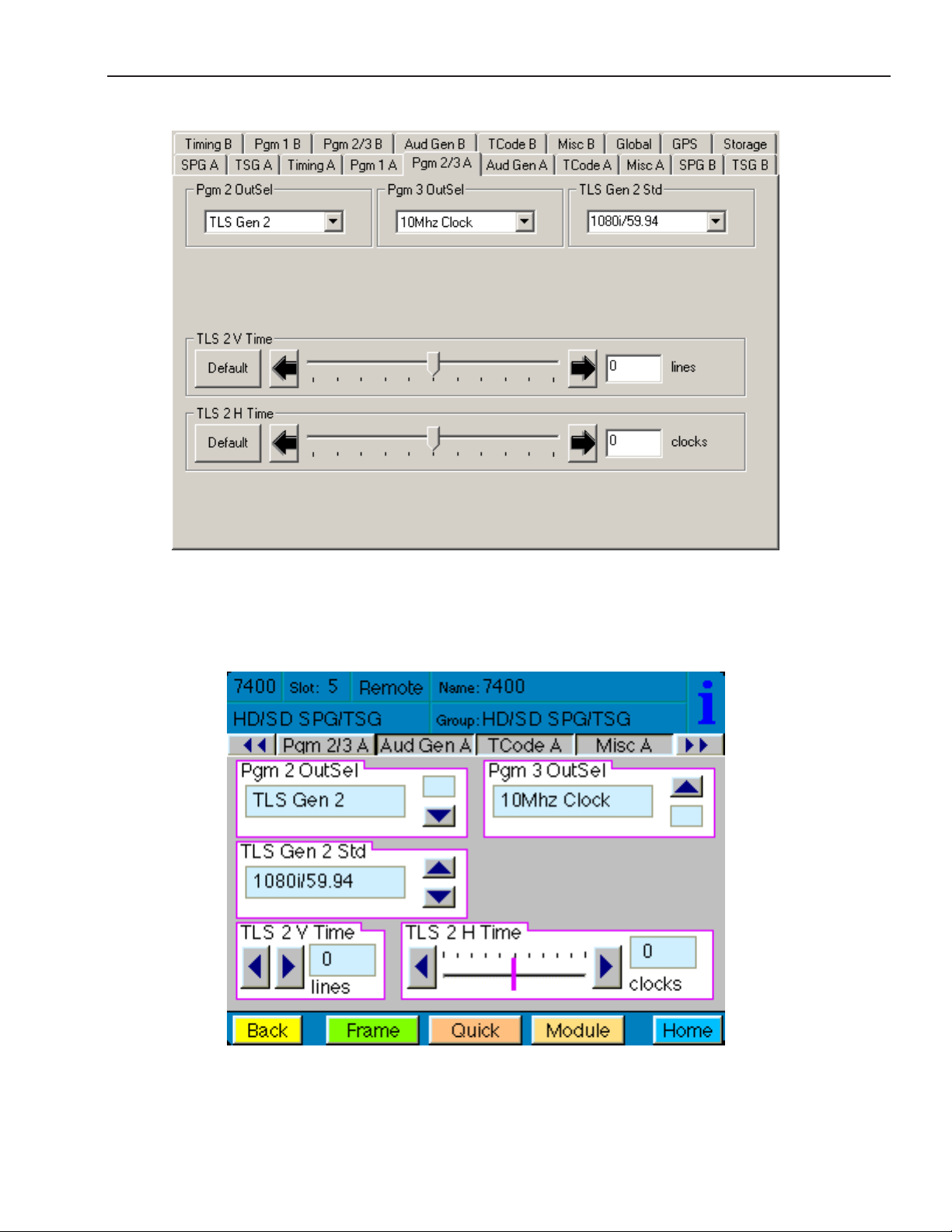
Programmable Outputs 2 A and 3 A Menu
Setting the Output, Tri-Level Sync Output Standard, Vertical Timing, and Horizontal
Timing for Programmable Outputs 2 A and 3 A
The Pgm 2/3 A menu shown below allows you to set Programmable Outputs 2 A and 3 A,
and the output standard, vertical timing and horizontal timing for Tri-Level Sync Generator 2.
This menu aects the Out 2 A and Out 3 A BNCs.
Use the controls to set the following:
• Pgm 2 OutSel – Aects Out 2 A BNC. Choose from:
TLS Gen 2
LTC Timecode
AES Audio 1/2
AES Audio 3/4
AES Audio 5/6
AES Audio 7/8
AES Audio 9/10
AES Audio 11/12
AES Audio 13/14
AES Audio 15/16
AES Silence
Word Clock
6Hz Pulse
10MHz Clock
• Pgm 3 OutSel – Aects Out 3 A BNC. Choose from:
TLS Gen 2
LTC Timecode
AES Audio 1/2
AES Audio 3/4
AES Audio 5/6
AES Audio 7/8
AES Audio 9/10
AES Audio 11/12
AES Audio 13/14
AES Audio 15/16
AES Silence
Word Clock
6Hz Pulse
10MHz Clock
www.ensembledesigns.com
Avenue 7400 and 9400 - Page 35
Page 36

Model 7400 HD/SD and Model 9400 3G/HD/SD Sync Pulse Generator and Test Signal Generator
• TLS Gen 2 Std – Choose the output standard for Tri-Level Sync Generator 2. Choose from:
720p/50
720p/59.94
720p/60
1080i/50
1080i/59.94
1080i/60
1080p/25
1080p/23.98
1080p/24
1080sF/25
1080sF/23.98
1080sF/24
• TLS 2 V Time – Set the vertical timing in lines for Tri-Level Sync Generator 2. Range is -1000
to 1000, default is 0. Use the slider controls or arrows to select a value or enter a value into the
number eld.
• TLS 2 H Time – Set the horizontal timing in clocks for Tri-Level Sync Generator 2. Range is
-2000 to 2000, default is 0. Use the slider controls or arrows to select a value or enter a value
into the number eld.
www.ensembledesigns.com
Avenue 7400 and 9400 - Page 36
Page 37
Model 7400 HD/SD and Model 9400 3G/HD/SD Sync Pulse Generator and Test Signal Generator
Pgm 2/3 A Avenue PC Menu
www.ensembledesigns.com
Pgm 2/3 A Touch Screen Menu
Avenue 7400 and 9400 - Page 37
Page 38

Model 7400 HD/SD and Model 9400 3G/HD/SD Sync Pulse Generator and Test Signal Generator
Audio Generator A Menu
Setting the Audio Generation and Routing Parameters for Audio Generator A
There are two generators on each 7400 or 9400, Generator A and Generator B. Each of the two
generators are identical, with completely independent controls. The two AES digital audio outputs
are always synchronous with all of the video outputs – regardless of format – because all of the video
outputs can be locked to a common time base. Multiple tone generators can be used to identify
multi-channel content. Each generator supports sixteen audio channels and the content of each
channel is independently programmable. Choices include adjustable frequency tone generators,
tone sweeps, silence, timecode, audio clip playback from the 7400’s secure digital card, and the
external AES input. All sixteen of these channels can be embedded in the SDI outputs. Each AES
output can select from any of the eight pairs that make up these sixteen channels.
This menu aects the Out 2 A and Out 3 A BNCs.
There are three types of audio output:
Embedded – audio embedded on the SDI output
AES – goes to user-programmable output 2 (Out 2 A) and 3 (Out 3 A)
Analog – output goes to 15-pin D connector
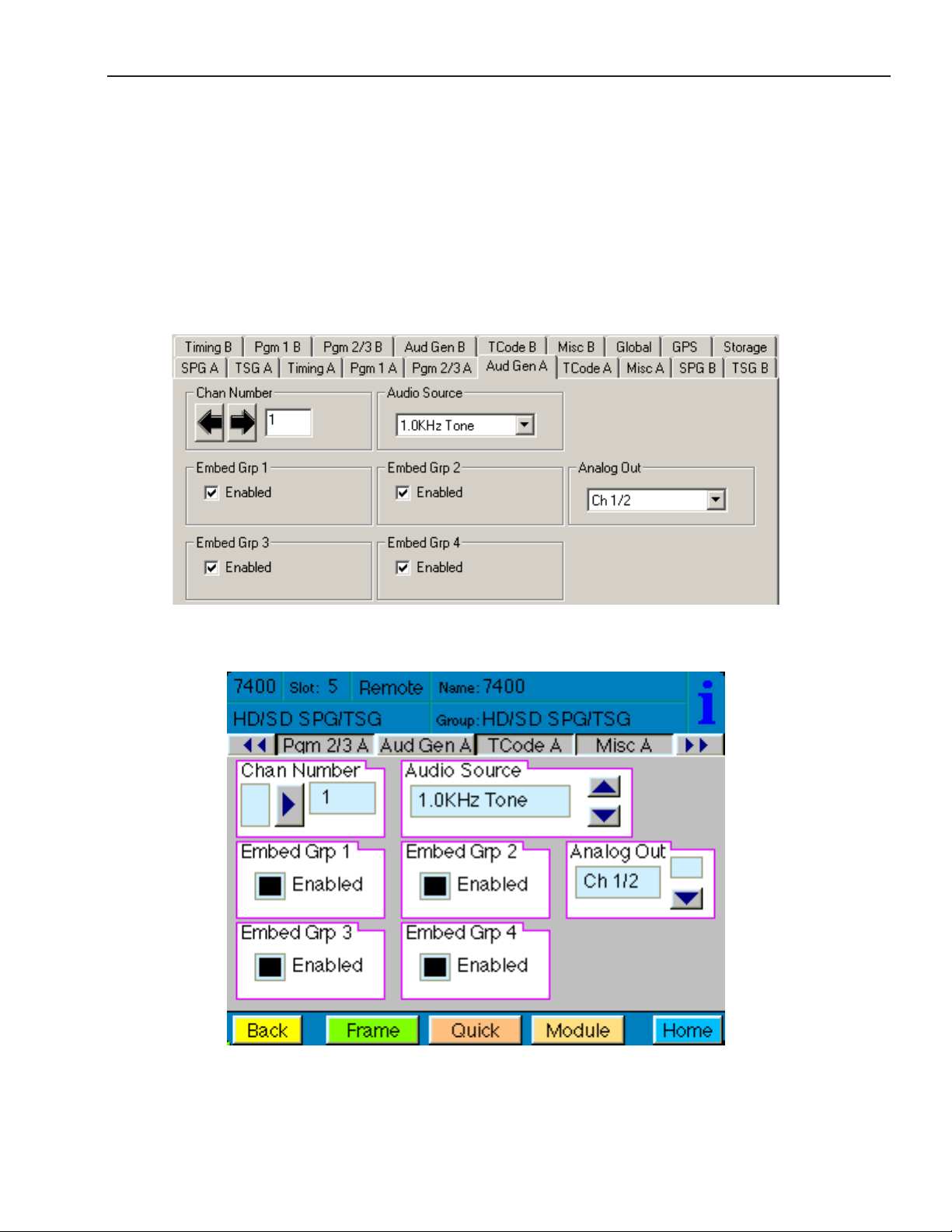
The Aud Gen A menu shown below allows you to set the Channel Number, the Audio Source, to
make Embedded Audio selections, and to choose the channel for Analog Out.
Use the controls to set the following:
• Chan Number – Available selections are 1 through 16
• Audio Source – Available selections are:
300Hz Tone
400Hz Tone
500Hz Tone
600Hz Tone
800Hz Tone
1.0KHz Tone
1.2KHz Tone
1.6KHz Tone
Silence
TSG Audio
Timecode
• Embed Grp 1 through 4
Group 1 includes channels 1/2 and 3/4
Group 2 includes channels 5/6 and 7/8
Group 3 includes channels 9/10 and 11/12
Group 4 includes channels 13/14 and 15/16
www.ensembledesigns.com
Avenue 7400 and 9400 - Page 38
Page 39
Model 7400 HD/SD and Model 9400 3G/HD/SD Sync Pulse Generator and Test Signal Generator
• Analog Out – Available selections are:
Channels 1/2
Channels 3/4
Channels 5/6
Channels 7/8
Channels 9/10
Channels 11/12
Channels 13/14
Channels 15/16
Aud Gen A Avenue PC Menu
Aud Gen A Touch Screen Menu
www.ensembledesigns.com
Avenue 7400 and 9400 - Page 39
Page 40

Model 7400 HD/SD and Model 9400 3G/HD/SD Sync Pulse Generator and Test Signal Generator
Timecode A Menu
Setting the Timecode Parameters for Timecode A
The TCode A menu shown below provides controls to select your timcode source, manually set or
oset timecode, insert VITC, and enable drop frame for Timecode Generator A.
TC Source – Available choices for timecode source are:
Manual/Jam – For entering a timecode manually.
GPS – For basing the timecode on the GPS source.
Ref VITC – For basing the timecode on the Reference vertical interval timecode.
Ref VITC w/ Oset – For basing the timecode on the Reference VITC, but oset by the
amount of time entered manually in the Hours/Minutes/Seconds controls.
• Manually set or oset the timecode – These controls are used to manually enter the time in
the Manual/Jam mode, and to manually oset the timecode when the timecode source is
Ref VITC with Oset. These controls will be greyed out and will not be usable when the
timecode source is GPS.
Hours – 0 through 23
Minutes – 0 through 59
Seconds – 0 through 59
• VITC Insert – Select from O or one of the following a pair of lines: 13, 15; 14, 16; 15, 17;
16, 18; 17, 19; 18, 20; 19, 21.
• Drop Frame – Select the checkbox to enable Drop Frame (dropping two frames every minute
except on every tenth minute) to allow timecode to match a real-time clock.
• Jam! – To manually enter the stating timecode value, enter the desired values in the Hours,
Minutes and Seconds elds, then click the Jam! button.
www.ensembledesigns.com
Avenue 7400 and 9400 - Page 40
Page 41

Model 7400 HD/SD and Model 9400 3G/HD/SD Sync Pulse Generator and Test Signal Generator
TCode A Avenue PC Menu
www.ensembledesigns.com
TCode A Touch Screen Menu
Avenue 7400 and 9400 - Page 41
Page 42

Model 7400 HD/SD and Model 9400 3G/HD/SD Sync Pulse Generator and Test Signal Generator
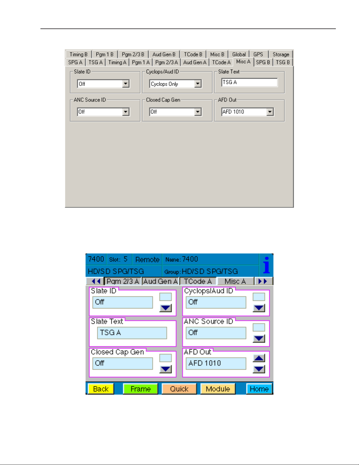
Misc A Menu: Setting the Slate, Closed Caption, and Aspect Ratio Parameters
The Misc A menu shown below provides controls for setting parameters for slate text that can overlay
the test pattern, a moving cyclops signal with audio pop and beep options, closed caption display
options, and AFD code selection for aspect ratio display options.
Use the controls to set the following:
• Slate ID – On or O. Select On if you want to use the Slate feature.
• Cyclops/Aud ID – Adds motion, audio pop or beep, and closed caption elements to the video
test signal which proves that the signal reaching this destination is a true live signal and not a
freeze frame from a frame synchronizer that has lost its input.
Available selections are: O, Cyclops Only, Cyclops Aud Pop, Cyclops Aud Beep.
• Slate Text – Enter the text that you want to overlay on the test pattern and hit enter on your
computer keyboard.
• ANC Source ID – On or O. When on, the ANC Source ID control embeds the rst 16 characters
of the Slate Text into the vertical interval as ancillary data.
• Closed Cap Gen – If you are testing closed captions, select one of the closed caption display
methods. This impacts how closed captions are displayed on screen.
Available selections are: O, Hello World, Knock Knock, Pop-On 1, Roll-Up 1, Fast Talk,
Special Char, Corners, Italics/UL, Indent, CC1 and CC2.
• AFD Out – Active Format Description code selection. This impacts how the aspect ratio of the
video content is treated when upconverting or downconverting between the 16:9 and 4:3
aspect ratios. The most commonly used AFD code selections are 1001 and 1010.
Available selections are:
AFD O
AFD0001
AFD0010
AFD0011
AFD0100
AFD0101
AFD0110
AFD0111
AFD1000
AFD1001
AFD1010
AFD1011
AFD1100
AFD1101
AFD1110
AFD1111
www.ensembledesigns.com
Avenue 7400 and 9400 - Page 42
Page 43
Model 7400 HD/SD and Model 9400 3G/HD/SD Sync Pulse Generator and Test Signal Generator
Misc A Avenue PC Menu
www.ensembledesigns.com
Misc A Touch Screen Menu
Avenue 7400 and 9400 - Page 43
Page 44

Model 7400 HD/SD and Model 9400 3G/HD/SD Sync Pulse Generator and Test Signal Generator
Sync Pulse Generator B Menu
Selecting the Reference Source and Output Standard for Sync Pulse Generator B
The SPG B menu controls the SDI Out B BNC. The standard selected determines what signal will be
output on the SDI Out B BNC.
Important: Additionally, the standard selected in the SPG B menu determines the frame rate family
for all of the Generator B BNC outputs (SDI Out B, Out 1 B, Out 2 B, Out 3 B). For example, if the
standard is set to SD 525 or 720p/59.94, then all Generator B outputs will be in the 59.94 Hz frame rate
family. If the standard is set to SD 625 or 1080i/50, then all Generator B outputs will be in the
50 Hz frame rate family.
To select the reference source and output standard of Sync Pulse Generator B, select the SPG B menu
shown below. Set the parameters for the Source and Standard elds. The standard that the module is
locked to is shown in the Sync Lock eld. Use the controls to set the following:
• Source – select the reference source for Generator B. Select from:
Internal/GPS – the module’s Internal Precision Standard reference signal, or the signal from
the GPS Receiver (with 7400-GPS Option installed). If the GPS signal is present, the 7400 will
lock to that. If the GPS signal is not present, the 7400 will lock to its internal TCXO.
Cong Ref – locks to the source selected as the Cong Ref in the Global menu. If you
choose Cong Ref, you must have congured that parameter in the Global menu.
See the “Global Menu” on page 61 for more information.
Other Gen – locks to the reference of Generator A.
• Sync Lock – reports what standard the module is locked to.
Note: If you are using the 7400-GPS option, be sure the H1 jumper on the main module is
installed in the GPS position to lock to the GPS reference signal. If the H1 jumper is installed
in the INT position it locks to the 7400 or 9400’s internal TCXO (Temperature Compensated
Crystal Oscillator). See the “7400-GPS Option Field Installation Procedure” on page 17 for more
information.
• Standard – select the output standard you want from the following:
720p/50 1080p/23.98
720p/59.94 1080p/24
720p/60 1080sF/25
1080i/50 1080sF/23.98
1080i/59.94 1080sF/24
1080i/60 SD 525
1080p/25 SD 625
www.ensembledesigns.com
Avenue 7400 and 9400 - Page 44
Page 45

Model 7400 HD/SD and Model 9400 3G/HD/SD Sync Pulse Generator and Test Signal Generator
SPG B Avenue PC Menu
www.ensembledesigns.com
SPG B Touch Screen Menu
Avenue 7400 and 9400 - Page 45
Page 46

Model 7400 HD/SD and Model 9400 3G/HD/SD Sync Pulse Generator and Test Signal Generator
Test Signal Generator B Menu
Selecting the Pattern Type, Output Standard and Y, Cr and Cb Channels for Test Signal
Generator B
The TSG B menu aects the SDI Out B BNC. It also aects the Out 1 B BNC if it has been set to
“Follow SDI.”
To set the type of test pattern for the output of Test Signal Generator B, select the TSG B menu
shown below. This menu also has controls for turning on and o the Y, Cr and Cb channels.
Use the controls to set the following:
• Pattern Type – Select the pattern group in the rst drop-down menu and the test signal in the
second drop-down menu.
Pattern Group Test Signal
Bars Full Field 75
Full Field 100
SMPTE 75
Split Field 75
Split Field 100
Red Field
RGB444 Bars A
RGB444 Bars B
Black Black
Flat Field 20
Flat Field 50
Flat Field 80
White
RGB444 Black
Ramp Video Ramp
Data Ramp
Shallow
5 Step
Sweep Sweep
MultiBurst
Pulse & Bar Full Field Window
Component
Timing Digital Blanking
Cosite
Interlace
Misc Black
Crosshatch
Safe Title
Pathological
Card Custom Test Patterns from Secure Digital Card
www.ensembledesigns.com
Avenue 7400 and 9400 - Page 46
Page 47

Model 7400 HD/SD and Model 9400 3G/HD/SD Sync Pulse Generator and Test Signal Generator
• Y Channel, Cr Channel, Cb Channel checkboxes – There are independent enables for each
channel so that Y, Cr and Cb can be controlled separately. You may choose to turn o the Y, Cr
and/or Cb Channels if desired for test purposes (such as setting up a monitor). To turn o one
or more channels, deselect the Enabled check box.
• Number – The selection available in this menu will reect the number of custom test
patterns loaded onto the SD storage card. A maximum of 255 user-created custom test
patterns can be loaded.
• Name – Each of the up to 255 custom test patterns will have a name when loaded from the
SD storage card. The name of the test pattern selected from the SD card will display in this
eld.
www.ensembledesigns.com
Avenue 7400 and 9400 - Page 47
Page 48

Model 7400 HD/SD and Model 9400 3G/HD/SD Sync Pulse Generator and Test Signal Generator
TSG B Avenue PC Menu
www.ensembledesigns.com
TSG B Touch Screen Menu
Avenue 7400 and 9400 - Page 48
Page 49

Model 7400 HD/SD and Model 9400 3G/HD/SD Sync Pulse Generator and Test Signal Generator
Timing B Menu
Setting the Timing for Generator B
The Timing B menu shown below allows you to set the timing of the Generator B outputs with
respect to the reference selected in the SPG B menu. This menu aects the SDI output, the principal
output of the generator, which applies to SDI Out B and Programmable Output 1 B (Out 1 B BNC).
Use the slider controls or arrows to select a value or enter a value into the number elds.
• Vert Timing – Set the vertical timing in lines. Range is -525 to 525, default is 0.
• Hor Timing – Set the horizontal timing in clocks. Range is -1716 to 1716, default is 0.
• Fine Phase – Set the ne phase of the Primary output in nanoseconds. Range is -35 to 35,
default is 0.
Timing B Avenue PC Menu
Timing B Touch Screen Menu
www.ensembledesigns.com
Avenue 7400 and 9400 - Page 49
Page 50

Model 7400 HD/SD and Model 9400 3G/HD/SD Sync Pulse Generator and Test Signal Generator
Programmable Output 1 B Menu
Setting the Output, Tri-Level Sync Output Standard, Fine Phase , Vertical Timing, and
Horizontal Timing for Programmable Output 1 B
The Pgm 1 B menu shown below allows you to set the Programmable Output 1 B, the Tri-Level Sync
output standard, vertical and horizontal timing and ne phase. This menu aects the Out 1 B BNC.
Note: The selections you make from the Pgm 1 OutSel and TLS Gen 1 Std drop-down menus have to
be from the same frame rate family as the standard selected in the SPG B menu.
Use the controls to set the following:
• Pgm 1 OutSel – Choose from:
Black
Color Bars
Follow SDI Out
TLS Gen 1
When “Follow SDI Out” is selected, the settings from the TSG B menu are being used.
• TLS Gen 1 Std – Choose an output standard from the following options:
720p/50
720p/59.94
720p/60
1080i/50
1080i/59.94
1080i/60
1080p/25
1080p/23.98
1080p/24
1080sF/25
1080sF/23.98
1080sF/24
Use the slider controls or arrows to select a value or enter a value into the number elds.
• Fine Phase – Set the ne phase of the output in nanoseconds. Range is -35 to 35, default is 0.
• Vert Timing – Set the vertical timing in lines. Range is -1000 to 1000, default is 0.
• Hor Timing – Set the horizontal timing in clocks. Range is -2000 to 2000, default is 0.
Note: If you select “Follow SDI Out” from the Pgm 1 OutSel drop-down menu, the Fine Phase,
Vert Timing and Hor Timing controls will be grayed out and will not be usable.
www.ensembledesigns.com
Avenue 7400 and 9400 - Page 50
Page 51

Model 7400 HD/SD and Model 9400 3G/HD/SD Sync Pulse Generator and Test Signal Generator
Pgm 1 B Avenue PC Menu
www.ensembledesigns.com
Pgm 1 B Touch Screen Menu
Avenue 7400 and 9400 - Page 51
Page 52

Model 7400 HD/SD and Model 9400 3G/HD/SD Sync Pulse Generator and Test Signal Generator
Programmable Output 2 B and 3 B Menu
Setting the Output, Tri-Level Sync Output Standard, Vertical Timing,and Horizontal
Timing for Programmable Output 2 B and 3 B
The Pgm 2/3 B menu shown below allows you to set the Programmable Output 2 B and 3 B, the
output standard and the vertical and horizontal timing for Tri-Level Sync Generator 2. This menu
aects the Out 2 B and Out 3 B BNCs.
Use the controls to set the following:
• Pgm 2 OutSel – Aects Out 2 B BNC. Choose from:
TLS Gen 2
LTC Timecode
AES Audio 1/2
AES Audio 3/4
AES Audio 5/6
AES Audio 7/8
AES Audio 9/10
AES Audio 11/12
AES Audio 13/14
AES Audio 15/16
AES Silence
Word Clock
6Hz Pulse
10MHz Clock
• Pgm 3 OutSel – Aects Out 3 B BNC. Choose from:
TLS Gen 2
LTC Timecode
AES Audio 1/2
AES Audio 3/4
AES Audio 5/6
AES Audio 7/8
AES Audio 9/10
AES Audio 11/12
AES Audio 13/14
AES Audio 15/16
AES Silence
Word Clock
6Hz Pulse
10MHz Clock
www.ensembledesigns.com
Avenue 7400 and 9400 - Page 52
Page 53

Model 7400 HD/SD and Model 9400 3G/HD/SD Sync Pulse Generator and Test Signal Generator
• TLS Gen 2 Std – Choose the output standard for Tri-Level Sync Generator 2. Choose from:
720p/50
720p/59.94
720p/60
1080i/50
1080i/59.94
1080i/60
1080p/25
1080p/23.98
1080p/24
1080sF/25
1080sF/23.98
1080sF/24
• TLS 2 V Time – Set the vertical timing in lines for Tri-Level Sync Generator 2. Range is -1000
to 1000, default is 0. Use the slider controls or arrows to select a value or enter a value into the
number eld.
• TLS 2 H Time – Set the horizontal timing in clocks for Tri-Level Sync Generator 2. Range is
-2000 to 2000, default is 0. Use the slider controls or arrows to select a value or enter a value
into the number eld.
www.ensembledesigns.com
Avenue 7400 and 9400 - Page 53
Page 54

Model 7400 HD/SD and Model 9400 3G/HD/SD Sync Pulse Generator and Test Signal Generator
Pgm 2/3 B Avenue PC Menu
www.ensembledesigns.com
Pgm 2/3 B Touch Screen Menu
Avenue 7400 and 9400 - Page 54
Page 55

Model 7400 HD/SD and Model 9400 3G/HD/SD Sync Pulse Generator and Test Signal Generator
Audio Generator B Menu
Setting the Audio Generation and Routing Parameters for Audio Generator B
There are two generators on each 7400 or 9400, Generator A and Generator B. Each of the two
generators are identical, with completely independent controls. The two AES digital audio outputs
are always synchronous with all of the video outputs – regardless of format – because all of the video
outputs can be locked to a common time base. Multiple tone generators can be used to identify
multi-channel content. Each generator supports sixteen audio channels and the content of each
channel is independently programmable. Choices include adjustable frequency tone generators,
tone sweeps, silence, timecode, audio clip playback from the 7400’s secure digital card, and the
external AES input. All sixteen of these channels can be embedded in the SDI outputs. Each AES
output can select from any of the eight pairs that make up these sixteen channels.
This menu aects the Out 2 B and Out 3 B BNCs.
There are three types of audio output:
Embedded – audio embedded on the SDI output
AES – goes to user-programmable output 2 (Out 2 B) and 3 (Out 3 B)
Analog – output goes to 15-pin D connector
The Aud Gen B menu shown below allows you to set the Channel Number, the Audio Source, to
make Embedded Audio selections, and to choose the channel for Analog Out.
Use the controls to set the following:
• Chan Number – Available selections are 1 through 16
• Audio Source – Available selections are:
300Hz Tone
400Hz Tone
500Hz Tone
600Hz Tone
800Hz Tone
1.0KHz Tone
1.2KHz Tone
1.6KHz Tone
Silence
TSG Audio
Timecode
• Embed Grp 1 through 4
Group 1 includes channels 1/2 and 3/4
Group 2 includes channels 5/6 and 7/8
Group 3 includes channels 9/10 and 11/12
Group 4 includes channels 13/14 and 15/16
www.ensembledesigns.com
Avenue 7400 and 9400 - Page 55
Page 56

Model 7400 HD/SD and Model 9400 3G/HD/SD Sync Pulse Generator and Test Signal Generator
• Analog Out – Available selections are:
Channels 1/2
Channels 3/4
Channels 5/6
Channels 7/8
Channels 9/10
Channels 11/12
Channels 13/14
Channels 15/16
Aud Gen B Avenue PC Menu
Aud Gen B Touch Screen Menu
www.ensembledesigns.com
Avenue 7400 and 9400 - Page 56
Page 57

Model 7400 HD/SD and Model 9400 3G/HD/SD Sync Pulse Generator and Test Signal Generator
Timecode B Menu
Setting the Timecode Parameters for Timecode B
The TCode B menu shown below provides controls to select your timcode source, manually set or
oset timecode, insert VITC, and enable drop frame for Timecode Generator B.
Use the controls to set the following:
TC Source – Available choices for timecode source are:
Manual/Jam – For entering a timecode manually.
GPS – For basing the timecode on the GPS source.
Ref VITC – For basing the timecode on the Reference vertical interval timecode.
Ref VITC w/ Oset – For basing the timecode on the Reference VITC, but oset by the
amount of time entered manually in the Hours/Minutes/Seconds controls.
Manual – Manually set or oset the timecode. These controls are used to manually enter the time in
the Manual/Jam mode, and to manually oset the timecode when the timecode source is Ref VITC
with Oset. These controls will be greyed out and will not be usable when the timecode source ids
GPS.
Hours – 0 through 23
Minutes – 0 through 59
Seconds – 0 through 59
• VITC Insert – Select from O or one of the following a pair of lines: 13, 15; 14, 16; 15, 17;
16, 18; 17, 19; 18, 20; 19, 21.
• Drop Frame – Select the checkbox to enable Drop Frame (dropping two frames every minute
except on every tenth minute) to allow timecode to match a real-time clock.
• Jam! – To manually enter the starting timecode value, enter the desired values in the Hours,
Minutes and Seconds elds, then click the Jam! button.
www.ensembledesigns.com
Avenue 7400 and 9400 - Page 57
Page 58
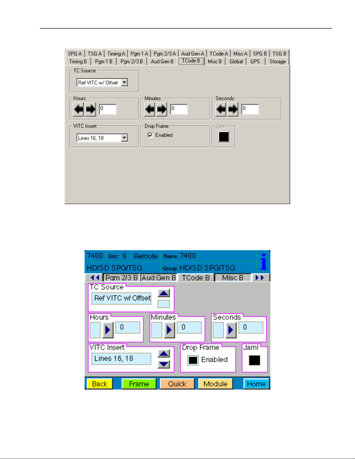
Model 7400 HD/SD and Model 9400 3G/HD/SD Sync Pulse Generator and Test Signal Generator
TCode B Avenue PC Menu
www.ensembledesigns.com
TCode B Touch Screen Menu
Avenue 7400 and 9400 - Page 58
Page 59

Model 7400 HD/SD and Model 9400 3G/HD/SD Sync Pulse Generator and Test Signal Generator
Misc B Menu: Setting the Slate, Closed Caption, and Aspect Ratio Parameters
The Misc B menu shown below provides controls for setting parameters for slate text that can overlay
the test pattern, a moving cyclops signal with audio pop and beep options, closed caption display
options, and AFD code selection for aspect ratio display options.
Use the controls to set the following:
• Slate ID – On or O. Select On if you want to use the Slate feature.
• Cyclops/Aud ID – Adds motion, audio pop or beep, and closed caption elements to the video
test signal which proves that the signal reaching this destination is a true live signal and not a
freeze frame from a frame synchronizer that has lost its input.
Available selections are: O, Cyclops Only, Cyclops Aud Pop, Cyclops Aud Beep.
• Slate Text – Enter the text that you want to overlay on the test pattern and hit enter on your
computer keyboard.
• ANC Source ID – On or O. When on, the ANC Source ID control embeds the rst 16 characters
of the Slate Text into the vertical interval as ancillary data.
• Closed Cap Gen – If you are testing closed captions, select one of the closed caption display
methods. This impacts how closed captions are displayed on screen.
Available selections are: O, Hello World, Knock Knock, Pop-On 1, Roll-Up 1, Fast Talk,
Special Char, Corners, Italics/UL, Indent, CC1 and CC2.
• AFD Out – Active Format Description code selection. This impacts how the aspect ratio of the
video content is treated when upconverting or downconverting between the 16:9 and 4:3
aspect ratios. The most commonly used AFD code selections are 1001 and 1010.
Available selections are:
AFD O
AFD0001
AFD0010
AFD0011
AFD0100
AFD0101
AFD0110
AFD0111
AFD1000
AFD1001
AFD1010
AFD1011
AFD1100
AFD1101
AFD1110
AFD1111
www.ensembledesigns.com
Avenue 7400 and 9400 - Page 59
Page 60

Model 7400 HD/SD and Model 9400 3G/HD/SD Sync Pulse Generator and Test Signal Generator
Misc B Avenue PC Menu
www.ensembledesigns.com
Misc B Touch Screen Menu
Avenue 7400 and 9400 - Page 60
Page 61

Model 7400 HD/SD and Model 9400 3G/HD/SD Sync Pulse Generator and Test Signal Generator
Global Menu
Setting Global Parameters for Module Reference and Audio Reference Levels
The parameters set in the Global menu aect the entire 7400 or 9400 module. These settings can be
applied to Generator A and Generator B.
The Global menu shown below allows you to set the parameters for Conguration Reference, Vertical
Interval Time Code, Digital Audio Reference Level, Analog Audio Tone Output and Composite Setup.
Use the controls to set the following:
• Cong Ref – Select the desired module reference from the External Reference (525, 625,
Tri-Level Sync or 10 MHz sine wave) or Master Reference (Frame Reference). The presence of
the reference will be reported in the adjacent Reference window.
• Ref VITC Line – Specify the line on which you want to put the Vertical Interval Time Code.
Available selections are: Line 12, Line 13, Line 14, Line 15, Line 16, Line 17, Line 18, Line 19.
• Reference – Reports what reference input is present from the following list:
No Ref, Ref 525, Ref 525 w/VITC, Ref 625, Ref 625 w/VITC, Ref TLS 720p60 (reports this for 59.94
and 60), Ref TLS 720p50, Ref TLS 1080i60 (reports this for 59.94 and 60), Ref TLS 1080i50 (also
reports this for 1080p 25 and 1080sF 25), Ref TLS 1080i24 (reports this for 1080p 23.98 or 24
and 1080sF 23.98 or 24), Ref 10MHz.
• Dig Ref Level – Digital Audio Reference Level. Applies to AES digital. -20dBFS or -18dBFS.
• Anlg Ref Level – Set the Analog Reference Level.
Available selections are: -10dB, -6dB, -4dB, 0dB, +4dB.
• Cpst Setup – Turns Composite Setup On or O for 525/60 Hz outputs. For most 60 Hz
applications, this option is typically enabled.
www.ensembledesigns.com
Avenue 7400 and 9400 - Page 61
Page 62

Model 7400 HD/SD and Model 9400 3G/HD/SD Sync Pulse Generator and Test Signal Generator
Global Avenue PC Menu
www.ensembledesigns.com
Global Touch Screen Menu
Avenue 7400 and 9400 - Page 62
Page 63

Model 7400 HD/SD and Model 9400 3G/HD/SD Sync Pulse Generator and Test Signal Generator
GPS Menu
The GPS menu shown below allows you to monitor the GPS status and set the parameters for UTC
Oset and Automatic Daylight Saving Time controls for Models 7400 and 9400 that have the optional
7400-GPS Option installed.
• GPS Status – Possible values are: Normal Operation; No Satellites; Antenna Open; Antenna
Shorted, Not Installed.
Normal Operation – the GPS function is operating normally.
No Satellites – This may indicate that the Avenue module is still in the process of
establishing a connection to the satellites. When rst setting up the GPS functionality, it is
normal for the process to take up to one hour to establish proper satellite connections.
Antenna Open – This status means that there is a loose cable connection, either between
the 7400 module and the GPS sub-module, or between the 7400 or 9400 and the antenna.
Make sure that you have installed the GPS submodule properly and installed the H1 jumper
in the GPS position. Check the GPS sub-module connections as well as the connections to
the antenna to make sure that everything is connected properly. See the “7400-GPS Option
Field Installation Procedure” on page 17 for more information.
Antenna Shorted – This indicates that there is a short somewhere between the Avenue
Frame and the antenna.
Not Installed – The GPS sub-module is not installed on the Avenue 7400 or 9400 module.
• UTC Oset – The UTC Oset is used to congure Models 7400 and 9400 so that the time that is
loaded into the timecode generator from the GPS is properly oset to the local time zone. The
UTC in the 7400 or 9400 module follows the North American practice.
The UTC Oset available menu options are -12 to 12, oset in hours. As an example, the setting
for the Pacic Time Zone in North America (Los Angeles) is an oset of -8
Note: UTC stands for Coordinated Universal Time, formerly known as GMT (Greenwich Mean
Time)
• Auto DST – Turn this feature On or O.
When the Auto DST function in On, timecode will automatically be adjusted forward by an
hour in the spring and back by an hour in the fall. If you want this auto functionality, leave the
Auto DST function On all year round.
If you want to adjust for Daylight Saving Time manually, turn the Auto DST function O and
change the UTC by one hour manually on the designated dates in the spring and fall.
Note that the calendar rules used for the beginning and ending of Daylight Saving Time by
the 7400 GPS Option are based upon the practice in North America.
www.ensembledesigns.com
Avenue 7400 and 9400 - Page 63
Page 64

Model 7400 HD/SD and Model 9400 3G/HD/SD Sync Pulse Generator and Test Signal Generator
• Date in TC – On or O. This control allows insertion of the date in all of the Timecode Outputs
of the Module
On – The date is inserted in all of the Timecode Outputs of the module, listed below. The
date is inserted in accordance with SMPTE Standard 309 in MJD (Modied Julian Date).
Timecode Outputs on Models 7400 and 9400:
LTC – “audio” style output
VITC – vertical interval in Analog SD
DVITC – vertical interval in SD SDI
ATC – vertical interval in HD SDI
www.ensembledesigns.com
Avenue 7400 and 9400 - Page 64
Page 65

Model 7400 HD/SD and Model 9400 3G/HD/SD Sync Pulse Generator and Test Signal Generator
GPS Avenue PC Menu
www.ensembledesigns.com
GPS Touch Screen Menu
Avenue 7400 and 9400 - Page 65
Page 66

Model 7400 HD/SD and Model 9400 3G/HD/SD Sync Pulse Generator and Test Signal Generator
Storage Menu
Loading Custom Test Signals, Viewing SD Card and RAM Status
With the Storage menu shown below, you can view the SD card status, load custom test signals from
the SD card, and view the amount of RAM available for both generators. Each 7400 and 9400 comes
with a 2 GB SD Flash Memory card for storing your custom test patterns. Additionally, each 7400 and
9400 ships with two 512 MB DDR2 RAM cards installed on the back of the module, these can be eld
upgraded to up to 2 GB each if desired.
Use the Load button to load your custom test signals from the SD Card.
The Storage menu also provides these reporting elds:
• SD Card Status – Reects the status of the SD Card; None, Error, Busy or Ready.
• RAM Module 1 – Shows the RAM capacity of Generator 1; None, Bad Memory, 256 MB,
512 MB, 1 GB, 2 GB.
• RAM Module 2 – Shows the RAM capacity of Generator 2; None, Bad Memory, 256 MB,
512 MB, 1 GB, 2 GB.
www.ensembledesigns.com
Storage Avenue PC Menu
Storage Touch Screen Menu
Avenue 7400 and 9400 - Page 66
Page 67

Model 7400 HD/SD and Model 9400 3G/HD/SD Sync Pulse Generator and Test Signal Generator
Troubleshooting
As a troubleshooting aid, the reference signal status and presence, power and CPU status can be easily
monitored from the front panel of this module using the front panel indicators.
Refer to the overall troubleshooting tips given below for Models 7400 and 9400:
No Generator A or Generator B LED indication
• Generator is not locked to its timing source. At least one of the Generator A
or Generator B LEDs should be lit to indicate the primary output line standard
and that it is locked to its timing source. Check source settings in the Global,
SPG A and SPG B menus.
Cannot control module
• Check status of CPU Run green LED. Should be blinking slowly and in unison
with other modules if System Control module is present. If not, try removing
the 7400 or 9400 module and plugging it in again to be sure it is seated
properly.
• System module may not be working properly if installed.
Module controls are grayed out
• Module is locked or access to module controls is restricted by the User Level
which is set in Avenue PC.
No signal out of module
• Check status of Ref green LEDs. One should be lit to indicate which reference
rate is currently being detected. If not, check the reference input or master
frame signal for presence and quality.
• Check cabling to input of module.
You may also refer to the technical support section of the Ensemble Designs web site for the latest
information on your equipment at the URL below:
http://www.ensembledesigns.com/support
www.ensembledesigns.com
Avenue 7400 and 9400 - Page 67
Page 68

Model 7400 HD/SD and Model 9400 3G/HD/SD Sync Pulse Generator and Test Signal Generator
Software Updating
Software upgrades for each module can be downloaded remotely if the optional System Control
module is installed. Software updates are easy to access and free on our web site:
www.ensembledesigns.com/support/avenue-support/
Use Avenue Mac or PC software to install the software update into your Avenue module. If you do not
have the required System Control Module and Avenue PC, modules can be sent back to the factory for
software upgrades.
www.ensembledesigns.com
Avenue 7400 and 9400 - Page 68
Page 69

Model 7400 HD/SD and Model 9400 3G/HD/SD Sync Pulse Generator and Test Signal Generator
Warranty and Factory Service
Warranty
Ensemble Designs, Inc. warrants this product to be free from defect in material and workmanship for a
period of 5 years from the date of delivery. During this 5 year warranty period, Ensemble Designs, Inc.
will repair any defective modules at Ensemble’s expense if the module should be determined to be
defective after consultation with a factory technician.
This warranty is not transferable. Any implied warranties expire at the expiration date of this warranty.
This warranty does not cover a defect that has resulted from improper or unreasonable use or
maintenance as determined by us. This warranty is void if there is any attempt to dissemble or adjust
factory set presets without factory authorization.
Factory Service
If you require service (under warranty or not), please contact Ensemble Designs and ask for Customer
Service before you return the unit. This will allow the service technician to provide any other
suggestions for identifying the problem and recommend possible solutions.
You may also refer to the technical support section of the Ensemble web site for the latest information
on your equipment at the URL below:
http://www.ensembledesigns.com/support
If you return equipment for repair, please get a Return Material Authorization Number (RMA) from the
factory rst.
Ship the product and a written description of the problem to:
Ensemble Designs, Inc.
Attention: Customer Service
RMA #####
870 Gold Flat Rd.
Nevada City, CA 95959 USA
tel: +1 530.478.1830
Fax: +1 530.478.1832
email: service@ensembledesigns.com
Be sure to put your RMA number on the outside of the box.
www.ensembledesigns.com
Avenue 7400 and 9400 - Page 69
Page 70

Model 7400 HD/SD and Model 9400 3G/HD/SD Sync Pulse Generator and Test Signal Generator
Specications for Models 7400 and 9400
Standards Supported
1080i 50, 59.94 or 60 Hz, SMPTE 274M -4,5,6
720p 50, 59.94 or 60 Hz, SMPTE 296M -1,2,3
1080p 23.98, 24 or 25 Hz, SMPTE 274M -9,10,11
1080sF 23.98, 24 or 25 Hz, RP211 -14,15,16
3 Gb/s Level A or Level B, SMPTE 424M, 425M 9400 only
625i 50
525i 59.94
Composite PAL, NTSC
Frame Rate Families
Each 7400 and 9400 has 2 identical Generators, each with a variety of outputs. All of the
outputs from a particular Generator must be selected within the same frame rate family.
50 Hz (625) Derived Family: 1080i/50, 720p/50, 1080p/25, 1080sF/25, 625i/50
59.94 Hz (525) Derived Family: 1080i/59.94, 720p/59.94, 1080p/23.98, 1080sF/23.98,
525i/59.94
60 Hz Derived Family: 1080i/60, 720p/60, 1080p/24, 1080sF/24
Reference Input
Number Two: External or Frame Master Reference
Signal Type PAL or NTSC composite video or HD Tri-Level Sync or
10 MHz 1V P-P sine or square
Return Loss >40 dB (applies to external ref input)
Serial Digital Outputs
Type HD Serial Digital 1.485 Gb/s, SMPTE 274M, 292M, 296M
HD Serial Digital 2.97 Gb/s, SMPTE 424M, 425M 9400 only
or SD Serial Digital 270 Mb/s, SMPTE 259M
Impedance 75 Ω
Return Loss >15 dB
Max Cable Length 300 meters for SD 270 Mb/s (Belden 1694A)
100 meters for HD 1.485 Gb/s (Belden 1694A)
70 meters for HD 2.97 Gb/s HD (Belden 1694A) 9400 only
Tri-Level Sync Outputs
Signal Type HD Tri-Level Sync
Output DC ±50 mV
Return Loss >30 dB to 30 MHz
www.ensembledesigns.com
Avenue 7400 and 9400 - Page 70
Page 71

Model 7400 HD/SD and Model 9400 3G/HD/SD Sync Pulse Generator and Test Signal Generator
Composite Outputs
Signal Type NTSC / PAL
Impedance 75 Ω
Return Loss >40 dB DC to 5.5 MHz
Frequency Response ±0.1 dB 0 to 5.0 MHz
Output DC ±50 mV
K Factor <1.0%
Dierential Phase <1.0 degree
SCH Phase ±2 degrees
Delay adjustable over full frame in sub degree steps
Color Framing tracks ref
Accuracy
Internal Reference (TCXO)
Freq Error <10
<±1 Hz F
-7
SC
GPS Option
Freq Error <10
-12
Stability
Analog Jitter <1 ns
Digital Jitter <0.2 UI (0.13 UI typical)
AES Jitter <1 ns
AES Audio Outputs
Type AES3id tone, 300 Hz to 1.6 KHz, or silent
Resolution 24 bit
Analog Audio Outputs
Number Two stereo pairs or four mono
Type tone, 300 Hz to 1.6 KHz, or silent
Impedance 30 Ω, balanced
Reference Level -10 to + 4 dBu, selectable
Additional Output Choices
Timecode DVITC on the SDI outputs
VITC on the composite outputs
LTC on BNC unbalanced or on HD-15 balanced, 1 V P-P
drop or non-drop for NTSC
date and time insertion when 7400-GPS Option is installed
6 Hz Pulse
Word Clock
10 MHz when locked to internal or GPS reference
www.ensembledesigns.com
Avenue 7400 and 9400 - Page 71
Page 72

Model 7400 HD/SD and Model 9400 3G/HD/SD Sync Pulse Generator and Test Signal Generator
Flash Memory
Number One
Type Secure Digital SD Flash Memory Card
Size 2 GB card included
Video File Type .tga
General Specications
Power Consumption 10 watts
Temperature Range 0 to 40°C ambient (all specs met)
Relative Humidity 0 to 95%, noncondensing
Altitude 0 to 10,000 ft
www.ensembledesigns.com
Avenue 7400 and 9400 - Page 72
Page 73

Model 7400 HD/SD and Model 9400 3G/HD/SD Sync Pulse Generator and Test Signal Generator
Glossary
AES/EBU
The digital audio standard dened as a joint eort of the Audio Engineering Society and the European
Broadcast Union. AES/EBU or AES3 describes a serial bitstream that carries two audio channels,
thus an AES stream is a stereo pair. The AES/EBU standard covers a wide range of sample rates and
quantizations (bit depths). In television systems, these will generally be 48 KHz and either 20 or 24 bits.
AFD
Active Format Description is a method to carry information regarding the aspect ratio of the video
content. The specication of AFD was standardized by SMPTE in 2007 and is now beginning to appear
in the marketplace. AFD can be included in both SD and HD SDI transport systems. There is no legacy
analog implementation. (See WSS).
ASI
A commonly used transport method for MPEG video streams, ASI or Asynchronous Serial Interface,
operates at the same 270 Mb/s data rate as SD SDI. This makes it easy to carry an ASI stream through
existing digital television infrastructure. Known more formally as DVB-ASI, this transport mechanism
can be used to carry multiple program channels.
Aspect Ratio
The ratio of the vertical and horizontal measurements of an image. 4:3 is the aspect ratio for standard
denition video formats and television and 16:9 for high denition. Converting formats of unequal
ratios is done by letterboxing (horizontal bars) or pillar boxing (vertical pillars) in order to keep the
original format’s aspect ratio.
Bandwidth
Strictly speaking, this refers to the range of frequencies (i.e. the width of the band of frequency) used
by a signal, or carried by a transmission channel. Generally, wider bandwidth will carry and reproduce
a signal with greater delity and accuracy.
Beta
Sony Beta SP video tape machines use an analog component format that is similar to SMPTE, but
diers in the amplitude of the color dierence signals. It may also carry setup on the luminance
channel.
Bit
A binary digit, or bit, is the smallest amount of information that can be stored or transmitted digitally
by electrical, optical, magnetic, or other means. A single bit can take on one of two states: On/O,
Low/High, Asserted/ Deasserted, etc. It is represented numerically by the numerals 1 (one) and 0
(zero). A byte, containing 8 bits, can represent 256 dierent states. The binary number 11010111, for
example, has the value of 215 in our base 10 numbering system. When a value is carried digitally, each
www.ensembledesigns.com
Avenue 7400 and 9400 - Page 73
Page 74

Model 7400 HD/SD and Model 9400 3G/HD/SD Sync Pulse Generator and Test Signal Generator
additional bit of resolution will double the number of dierent states that can be represented. Systems
that operate with a greater number of bits of resolution, or quantization, will be able to capture a
signal with more detail or delity. Thus, a video digitizer with 12 bits of resolution will capture 4 times
as much detail as one with 10 bits.
Blanking
The Horizontal and Vertical blanking intervals of a television signal refer to the time periods between
lines and between elds. No picture information is transmitted during these times, which are required
in CRT displays to allow the electron beam to be repositioned for the start of the next line or eld.
They are also used to carry synchronizing pulses which are used in transmission and recovery of the
image. Although some of these needs are disappearing, the intervals themselves are retained for
compatibility purposes. They have turned out to be very useful for the transmission of additional
content, such as teletext and embedded audio.
CAV
Component Analog Video. This is a convenient shorthand form, but it is subject to confusion. It is
sometimes used to mean ONLY color dierence component formats (SMPTE or Beta), and other times
to include RGB format. In any case, a CAV signal will always require 3 connectors – either Y/R-Y/B-Y,
or R/G/B.
Checkeld
A Checkeld signal is a special test signal that stresses particular aspects of serial digital transmission.
The performance of the Phase Locked-Loops (PLLs) in an SDI receiver must be able to tolerate long
runs of 0’s and 1’s. Under normal conditions, only very short runs of these are produced due to a
scrambling algorithm that is used. The Checkeld, also referred to as the Pathological test signal, will
“undo” the scrambling and cause extremely long runs to occur. This test signal is very useful for testing
transmission paths.
Chroma
The color or chroma content of a signal, consisting of the hue and saturation of the image.
See also Color Dierence.
Component
In a component video system, the totality of the image is carried by three separate but related
components. This method provides the best image delity with the fewest artifacts, but it requires
three independent transmission paths (cables). The commonly used component formats are
Luminance and Color Dierence (Y/Pr/Pb), and RGB. It was far too unwieldy in the early days of color
television to even consider component transmission.
Composite
Composite television dates back to the early days of color transmission. This scheme encodes the
color dierence information onto a color subcarrier. The instantaneous phase of the subcarrier is the
color’s hue, and the amplitude is the color’s saturation or intensity. This subcarrier is then added onto
the existing luminance video signal. This trick works because the subcarrier is set at a high enough
frequency to leave spectrum for the luminance information. But it is not a seamless matter to pull
www.ensembledesigns.com
Avenue 7400 and 9400 - Page 74
Page 75

Model 7400 HD/SD and Model 9400 3G/HD/SD Sync Pulse Generator and Test Signal Generator
the signal apart again at the destination in order to display it or process it. The resultant artifacts of
dot crawl (also referred to as chroma crawl) are only the most obvious result. Composite television is
the most commonly used format throughout the world, either as PAL or NTSC. It is also referred to as
Encoded video.
Color Dierence
Color Dierence systems take advantage of the details of human vision. We have more acuity in our
black and white vision than we do in color. This means that we need only the luminance information to
be carried at full bandwidth, we can scrimp on the color channels. In order to do this, RGB information
is converted to carry all of the luminance (Y is the black and white of the scene) in a single channel.
The other two channels are used to carry the “color dierence”. Noted as B-Y and R-Y, these two signals
describe how a particular pixel “diers” from being purely black and white. These channels typically
have only half the bandwidth of the luminance.
Decibel (dB)
The decibel is a unit of measure used to express the ratio in the amplitude or power of two signals. A
dierence of 20 dB corresponds to a 10:1 ratio between two signals, 6 dB is approximately a 2:1 ration.
Decibels add while the ratios multiply, so 26 dB is a 20:1 ratio, and 14 dB is a 5:1 ratio. There are several
special cases of the dB scale, where the reference is implied. Thus, dBm refers to power relative to 1
milliwatt, and dBu refers to voltage relative to .775V RMS. The original unit of measure was the Bel
(10 times bigger), named after Alexander Graham Bell.
dBFS
In Digital Audio systems, the largest numerical value that can be represented is referred to as Full
Scale. No values or audio levels greater than FS can be reproduced because they would be clipped.
The nominal operating point (roughly corresponding to 0 VU) must be set below FS in order to have
headroom for audio peaks. This operating point is described relative to FS, so a digital reference level
of -20 dBFS has 20 dB of headroom before hitting the FS clipping point.
DVI
Digital Visual Interface. DVI-I (integrated) provides both digital and analog connectivity. The larger
group of pins on the connector are digital while the four pins on the right are analog.
EDH
Error Detection and Handling is a method to verify proper reception of an SDI or HD-SDI signal at the
destination. The originating device inserts a data packet in the vertical interval of the SDI signal and
every line of the HD signal which contains a checksum of the entire video frame. This checksum is
formed by adding up the numerical values of all of the samples in the frame, using a complex formula.
At the destination this same formula is applied to the incoming video and the resulting value is
compared to the one included in the transmission. If they match, then the content has all arrived with
no errors. If they don’t, then an error has occurred.
Embedded Audio
Digital Audio can be carried along in the same bitstream as an SDI or HD-SDI signal by taking
advantage of the gaps in the transmission which correspond to the horizontal and vertical intervals
www.ensembledesigns.com
Avenue 7400 and 9400 - Page 75
Page 76

Model 7400 HD/SD and Model 9400 3G/HD/SD Sync Pulse Generator and Test Signal Generator
of the television waveform. This technique can be very cost eective in transmission and routing, but
can also add complexity to signal handling issues because the audio content can no longer be treated
independently of the video.
Eye Pattern
To analyze a digital bitstream, the signal can be displayed visually on an oscilloscope by triggering the
horizontal timebase with a clock extracted from the stream. Since the bit positions in the stream form
a very regular cadence, the resulting display will look like an eye – an oval with slightly pointed left and
right ends. It is easy to see from this display if the eye is “open”, with a large central area that is free of
negative or positive transitions, or “closed” where those transitions are encroaching toward the center.
In the rst case, the open eye indicates that recovery of data from the stream can be made reliably and
with few errors. But in the closed case data will be dicult to extract and bit errors will occur. Generally
it is jitter in the signal that is the enemy of the eye.
Frame Sync
A Frame Synchronizer is used to synchronize the timing of a video signal to coincide with a timing
reference (usually a color black signal that is distributed throughout a facility). The synchronizer
accomplishes this by writing the incoming video into a frame buer memory under the timing
direction of the sync information contained in that video. Simultaneously the memory is being read
back by a timing system that is genlocked to a house reference. As a result, the timing or alignment of
the video frame can be adjusted so that the scan of the upper left corner of the image is happening
simultaneously on all sources. This is a requirement for both analog and digital systems in order to
perform video eects or switch glitch-free in a router. Frame synchronization can only be performed
within a single television line standard. A synchronizer will not convert an NTSC signal to a PAL signal,
it takes a standards converter to do that.
Frequency Response
A measurement of the accuracy of a system to carry or reproduce a range of signal frequencies. Similar
to Bandwidth.
H.264
The latest salvo in the compression wars is H.264 which is also known as MPEG-4 Part 10. MPEG-4
promises good results at just half the bit rate required by MPEG-2.
HD
High Denition. This two letter acronym has certainly become very popular. Here we thought it was all
about the pictures – and the radio industry stole it.
HDMI
The High Denition Multimedia Interface comes to us from the consumer marketplace where it is
becoming the de facto standard for the digital interconnect of display devices to audio and video
sources. It is an uncompressed, all-digital interface that transmits digital video and eight channels of
digital audio. HDMI is a bit serial interface that carries the video content in digital component form
over multiple twisted-pairs. HDMI is closely related to the DVI interface for desktop computers and
their displays.
www.ensembledesigns.com
Avenue 7400 and 9400 - Page 76
Page 77

Model 7400 HD/SD and Model 9400 3G/HD/SD Sync Pulse Generator and Test Signal Generator
IEC
The International Electrotechnical Commission provides a wide range of worldwide standards. They
have provided standardization of the AC power connection to products by means of an IEC line cord.
The connection point uses three at contact blades in a triangular arrangement, set in a rectangular
connector. The IEC specication does not dictate line voltage or frequency. Therefore, the user must
take care to verify that a device either has a universal input (capable of 90 to 230 volts, either 50 or 60
Hz), or that a line voltage switch, if present, is set correctly.
Interlace
Human vision can be fooled to see motion by presenting a series of images, each with a small change
relative to the previous image. In order to eliminate the icker, our eyes need to see more than 30
images per second. This is accomplished in television systems by dividing the lines that make up
each video frame (which run at 25 or 30 frames per second) into two elds. All of the odd-numbered
lines are transmitted in the rst eld, the even-numbered lines are in the second eld. In this way, the
repetition rate is 50 or 60 Hz, without using more bandwidth. This trick has worked well for years, but
it introduces other temporal artifacts. Motion pictures use a slightly dierent technique to raise the
repetition rate from the original 24 frames that make up each second of lm—they just project each
one twice.
IRE
Video level is measured on the IRE scale, where 0 IRE is black, and 100 IRE is full white. The actual
voltages that these levels correspond to can vary between formats.
ITU-R 601
This is the principal standard for standard denition component digital video. It denes the luminance
and color dierence coding system that is also referred to as 4:2:2. The standard applies to both PAL
and NTSC derived signals. They both will result in an image that contains 720 pixels horizontally, with
486 vertical pixels in NTSC, and 576 vertically in PAL. Both systems use a sample clock rate of 27 MHz,
and are serialized at 270 Mb/s.
Jitter
Serial digital signals (either video or audio) are subject to the eects of jitter. This refers to the
instantaneous error that can occur from one bit to the next in the exact position of each digital
transition. Although the signal may be at the correct frequency on average, in the interim it varies.
Some bits come slightly early, others come slightly late. The measurement of this jitter is given
either as the amount of time uncertainty or as the fraction of a bit width. For 270 Mb/s SD video, the
allowable jitter is 740 picoseconds, or 0.2 UI (Unit Interval – one bit width). For 1.485 Gb/s HD, the
same 0.2UI spec corresponds to just 135 pico seconds.
Luminance
The “black & white” content of the image. Human vision had more acuity in luminance, so television
systems generally devote more bandwidth to the luminance content. In component systems, the
luminance is referred to as Y.
www.ensembledesigns.com
Avenue 7400 and 9400 - Page 77
Page 78

Model 7400 HD/SD and Model 9400 3G/HD/SD Sync Pulse Generator and Test Signal Generator
MPEG
The Moving Picture Experts Group is an industry group that develops standards for the compression
of moving pictures for television. Their work is an on-going eort. The understanding of image
processing and information theory is constantly expanding. And the raw bandwidth of both the
hardware and software used for this work is ever increasing. Accordingly, the compression methods
available today are far superior to the algorithms that originally made the real-time compression and
decompression of television possible. Today, there are many variations of these techniques, and the
term MPEG has to some extent become a broad generic label.
Metadata
This word comes from the Greek, meta means ‘beyond’ or ‘after’. When used as a prex to ‘data’, it can
be thought of as ‘data about the data’. In other words, the metadata in a data stream tells you about
that data – but it is not the data itself. In the television industry, this word is sometimes used correctly
when, for example, we label as metadata the timecode which accompanies a video signal. That
timecode tells you something about the video, i.e. when it was shot, but the timecode in and of itself
is of no interest. But in our industry’s usual slovenly way in matters linguistic, the term metadata has
also come to be used to describe data that is associated with the primary video in a datastream. So
embedded audio will (incorrectly) be called metadata when it tells us nothing at all about the pictures.
Oh well.
Multi-mode
Multi-mode bers have a larger diameter core than single mode bers (either 50 or 62.5 microns
compared to 9 microns), and a correspondingly larger aperture. It is much easier to couple light energy
into a multi-mode ber, but internal reections will cause multiple “modes” of the signal to propagate
down the ber. This will degrade the ability of the ber to be used over long distances.
See also Single Mode.
NTSC
The color television encoding system used in North America was originally dened by the National
Television Standards Committee. This American standard has also been adopted by Canada, Mexico,
Japan, Korea, and Taiwan. (This standard is referred to disparagingly as Never Twice Same Color.)
Optical
An optical interface between two devices carries data by modulating a light source. This light source
is typically a laser or laser diode (similar to an LED) which is turned on and o at the bitrate of the
datastream. The light is carried from one device to another through a glass ber. The ber’s core acts
as a waveguide or lightpipe to carry the light energy from one end to another. Optical transmission
has two very signicant advantages over metallic copper cables. Firstly, it does not require that the
two endpoint devices have any electrical connection to each other. This can be very advantageous
in large facilities where problems with ground loops appear. And secondly, and most importantly, an
optical interface can carry a signal for many kilometers or miles without any degradation or loss in the
recovered signal. Copper is barely useful at distances of just 1000 feet.
www.ensembledesigns.com
Avenue 7400 and 9400 - Page 78
Page 79

Model 7400 HD/SD and Model 9400 3G/HD/SD Sync Pulse Generator and Test Signal Generator
Oversampling
A technique to perform digital sampling at a multiple of the required sample rate. This has the
advantage of raising the Nyquist Rate (the maximum frequency which can be reproduced by a given
sample rate) much higher than the desired passband. This allows more easily realized anti-aliasing
lters.
PAL
During the early days of color television in North America, European broadcasters developed a
competing system called Phase Alternation by Line. This slightly more complex system is better able
to withstand the dierential gain and phase errors that appear in ampliers and transmission systems.
Engineers at the BBC claim that it stands for Perfection At Last.
Pathological Test Pattern – see Checkeld
Progressive
An image scanning technique which progresses through all of the lines in a frame in a single pass.
Computer monitors all use progressive displays. This contrasts to the interlace technique common to
television systems.
Return Loss
An idealized input or output circuit will exactly match its desired impedance (generally 75 ohms) as a
purely resistive element, with no reactive (capacitive or inductive) elements. In the real world, we can
only approach the ideal. So, our real inputs and outputs will have some capacitance and inductance.
This will create impedance matching errors, especially at higher frequencies. The Return Loss of
an input or output measures how much energy is returned (reected back due to the impedance
mismatch). For digital circuits, a return loss of 15 dB is typical. This means that the energy returned is
15 dB less than the original signal. In analog circuits, a 40 dB gure is expected.
RGB
RGB systems carry the totality of the picture information as independent Red, Green, and Blue signals.
Television is an additive color system, where all three components add to produce white. Because the
luminance (or detail) information is carried partially in each of the RGB channels, all three must be
carried at full bandwidth in order to faithfully reproduce an image.
ScH Phase
Used in composite systems, ScH Phase measures the relative phase between the leading edge of sync
on line 1 of eld 1 and a continuous subcarrier sinewave. Due to the arithmetic details of both PAL and
NTSC, this relationship is not the same at the beginning of each frame. In PAL, the pattern repeats ever
4 frames (8 elds) which is also known as the Bruch Blanking sequence. In NTSC, the repeat is every 2
frames (4 elds). This creates enormous headaches in editing systems and the system timing of analog
composite facilities.
www.ensembledesigns.com
Avenue 7400 and 9400 - Page 79
Page 80

Model 7400 HD/SD and Model 9400 3G/HD/SD Sync Pulse Generator and Test Signal Generator
SDI
Serial Digital Interface. This term refers to inputs and outputs of devices that support serial digital
component video. This could refer to standard denition at 270 Mb/s, HD SDI or High Denition Serial
Digital video at 1.485 Gb/s, or to the newer 3G standard of High Denition video at 2.97 Gb/s.
SMPTE
The Society of Motion Picture and Television Engineers is a professional organization which has done
tremendous work in setting standards for both the lm and television industries. The term “SMPTE’” is
also shorthand for one particular component video format - luminance and color dierence.
Single Mode
A Single mode (or mono mode) optical ber carries an optical signal on a very small diameter (9
micron) core surrounded with cladding. The small diameter means that no internally reected
lightwaves will be propagated. Thus only the original “mode” of the signal passes down the ber. A
single mode ber used in an optical SDI system can carry a signal for up to 20 kilometers. Single mode
bers require particular care in their installation due to the extremely small optical aperture that they
present at splice and connection points. See also Multi-mode.
TBC
A Time Base Corrector is a system to reduce the Time Base Error in a signal to acceptable levels. It
accomplishes this by using a FIFO (First In, First Out) memory. The incoming video is written into the
memory using its own jittery timing. This operation is closely associated with the actual digitization of
the analog signal because the varying position of the sync timing must be mimicked by the sampling
function of the analog to digital converter. A second timing system, genlocked to a stable reference,
is used to read the video back out of the memory. The memory acts as a dynamically adjusting delay
to smooth out the imperfections in the original signal’s timing. Very often a TBC will also function as a
Frame Synchronizer. See also Frame Sync.
Time Base Error
Time base error is present when there is excessive jitter or uncertainty in the line to line output
timing of a video signal. This is commonly associated with playback from video tape recorders, and
is particularly severe with consumer type heterodyne systems like VHS. Time base error will render a
signal unusable for broadcast or editing purposes.
Timecode
Timecode, a method to uniquely identify and label every frame in a video stream, has become one of
the most recognized standards ever developed by SMPTE. It uses a 24 hour clock, consisting of hours,
minutes, seconds, and television frames. Originally recorded on a spare audio track, this 2400 baud
signal was a signicant contributor to the development of video tape editing. We now refer to this as
LTC or Longitudinal Time Code because it was carried along the edge of the tape. This allowed it to
be recovered in rewind and fast forward when the picture itself could not. Timecode continues to be
useful today and is carried in the vertical interval as VITC, and as a digital packet as DVITC. Timecode is
the true metadata.
www.ensembledesigns.com
Avenue 7400 and 9400 - Page 80
Page 81

Model 7400 HD/SD and Model 9400 3G/HD/SD Sync Pulse Generator and Test Signal Generator
Tri-Level Sync
For many, many years, television systems used composite black as a genlock reference source. This
was a natural evolution from analog systems to digital implementations. With the advent of High
Denition television, with even higher data rates and tighter jitter requirements, problems with this
legacy genlock signal surfaced. Further, a reference signal with a 50 or 60 Hz frame rate was useless
with 24 Hz HD systems running at lm rates. Today we can think of composite black as a bi-level sync
signal – it has two levels, one at sync tip and one at blanking. For HD systems, Tri-Level Sync, which has
the same blanking level (at ground) of bi-level sync, but the sync pulse now has both a negative and
a positive element. This keeps the signal symmetrically balanced so that its DC content is zero. And it
also means that the timing picko point is now at the point where the signal crosses blanking and is
no longer subject to variation with amplitude. This makes Tri-Level Sync a much more robust signal
and one which can be delivered with less jitter.
USB
The Universal Serial Bus, developed in the computer industry to replace the previously ubiquitous
RS-232 serial interface, now appears in many dierent forms and with many dierent uses. It actually
forms a small local area network, allowing multiple devices to coexist on a single bus where they can
be individually addressed and accessed.
VGA
Video Graphics Array. Traditional 15-pin, analog interface between a PC and monitor.
Word Clock
Use of Word Clock to genlock digital audio devices developed in the audio recording industry. Early
digital audio products were interconnected with a massive parallel connector carrying a twisted pair
for every bit in the digital audio word. A clock signal, which is a square wave at the audio sampling
frequency, is carried on a 75 ohm coaxial cable. Early systems would daisychain this 44.1 or 48 kilohertz
clock from one device to another with coax cable and Tee connectors. On the rising edge of this Work
Clock these twisted pairs would carry the left channel, while on the falling edge, they would carry the
right channel. In most television systems using digital audio, the audio sample clock frequency (and
hence the ‘genlock’ between the audio and video worlds) is derived from the video genlock signal. But
products that are purely audio, with no video reference capability, may still require Word Clock.
WSS
Wide Screen Signaling is used in the PAL/625 video standards, both in analog and digital form, to
convey information about the aspect ratio and format of the transmitted signal. Carried in the vertical
interval, much like closed captioning, it can be used to signal a television receiver to adjust its vertical
or horizontal sizing to reect incoming material. Although an NTSC specication for WSS exists, it
never achieved any traction in the marketplace.
YUV
Strictly speaking, YUV does not apply to component video. The letters refer to the Luminance (Y), and
the U and V encoding axes using in the PAL composite system. Since the U axis is very close to the B-Y
axis, and the V axis is very close to the R-Y axis, YUV is often used as a sort of shorthand for the more
long-winded “Y/R-Y/B-Y”.
www.ensembledesigns.com
Avenue 7400 and 9400 - Page 81
Page 82

Model 7400 HD/SD and Model 9400 3G/HD/SD Sync Pulse Generator and Test Signal Generator
Y/Cr/Cb
In digital component video, the luminance component is Y, and the two color dierence signals are Cr
(R-Y) and Cb (B-Y).
Y/Pr/Pb
In analog component video, the image is carried in three components. The luminance is Y, the R-Y
color dierence signal is Pr, and the B-Y color dierence signal is Pb.
www.ensembledesigns.com
Avenue 7400 and 9400 - Page 82
 Loading...