

Page 1

This data pack provides detailed installation, configuration and operation information for
the 8500 Series Video Processing Synchronizer module along with the 8410, 8415 or
8510 Audio Processing and 8520 DNR option submodules as part of the Avenue Signal
Integration System.
The module information in this data pack is organized into the following sections:
• 8500 Series Overview
• Applications
• Installation
°
Configuring Rear BNCs
• Cabling
• Module Configuration and Control
°
Front Panel Controls and Indicators
°
Avenue PC Remote Control
°
Avenue Touch Screen Remote Control
• Troubleshooting
• Software Updating
• Warranty and Factory Service
• Specifications
8500-1
Model 8500 Series
Video and Audio
Processing
Data Pack
ENSEMBLE
DESIGNS
Revision 5.1 SW v2.2.6
Page 2

8500 SERIES OVERVIEW
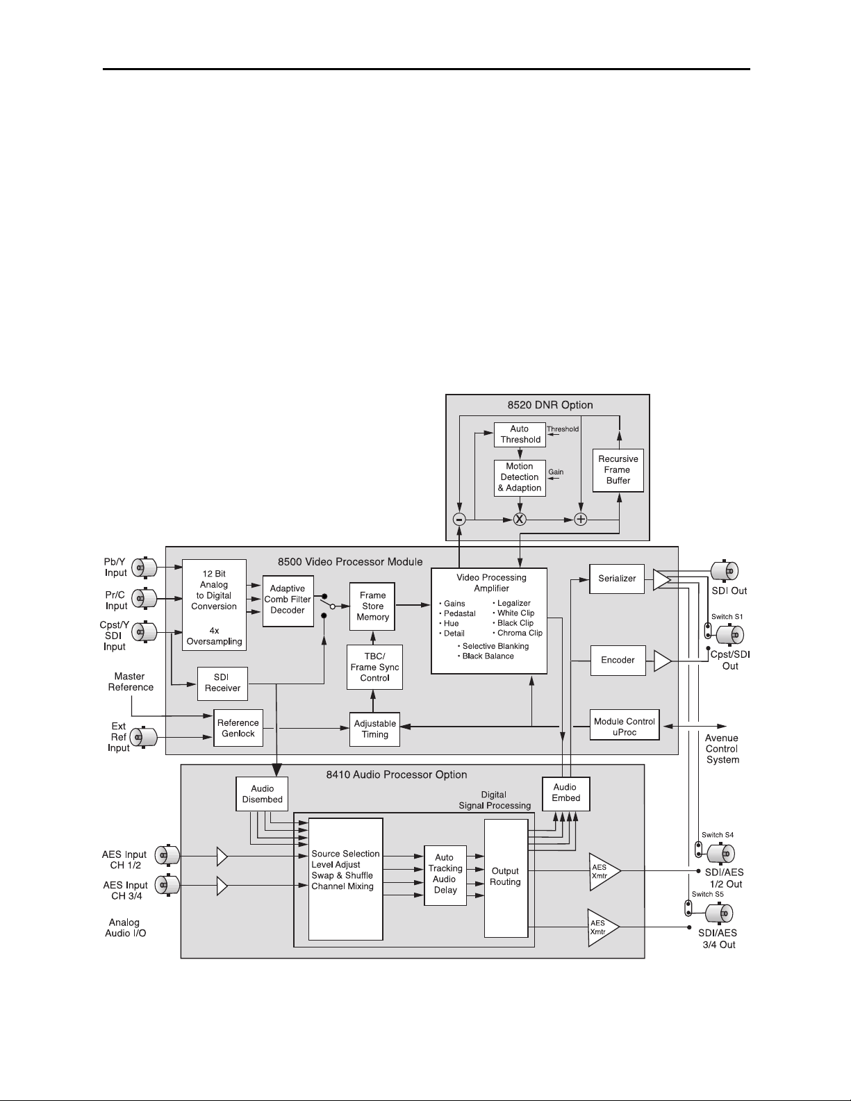
The 8500 Video Processing Frame Synchronizer, along with its optional submodules,
provides a real "do it all" module. A block diagram of module functions is shown on the
following page.
With component and composite analog inputs as well as serial digital video input, the
8500 accepts nearly any signal in a facility. The SDI input is carried at full uncompressed
bandwidth throughout the entire module and EDH monitoring of the digital input alerts
you to any incoming problem. Analog inputs are 4x oversampled at 12 bits of resolution.
Composite signals are decoded using an adaptive comb filter. The proper 525 or 625
standard is automatically selected by the 8500 module.
Input video is synchronized to a house reference by a TBC/Frame Synchronizer. Noisy and
jittery analog sources are faithfully tracked to provide a steady, genlocked output,
ensuring proper time base correction for virtually any source, even a consumer VHS
machine. Select the SDI input and the 8500 is a serial digital frame sync.
The 8500 has a full-featured Proc Amp for adjustment of every signal parameter. Proc
controls include Video and Chroma Gain, NTSC style hue rotation, Black Balance, and
pedestal. Black and White clips can be set to prevent excessive signal excursions. To help
optimize the settings in the Proc Amp, a Split Screen mode allows you to compare the
processed output with the original material.
A Detail Enhancer recovers information that has been lost due to poor frequency response
in upstream systems.Certain values represented in serial digital component may be illegal
in the NTSC or PAL composite domains. The Predictive Composite Clipper mode identifies picture elements that would be illegal in analog composite, and limits color saturation
and luminance excursions.
Selective (toothed) vertical blanking lets you choose to pass or strip content in the vertical
interval on a line by line and field by field basis.
The 8500 has simultaneous SDI and analog composite outputs. They are fully timed to
your house reference, including the subcarrier and ScH phase of the composite output.
The analog output is constructed at 8x oversampling with 12 bits of quantizing resolution.
The 8520 Digital Video Noise Reducer (DNR) is an optional sub module that can be added
to the 8500 Video Processing Frame Synchronizer. The noise reduction process is downstream of the 8500 Proc Amp controls. The 8520 DNR can be used with any 8500 video
input source. It only adds 4 microseconds to the throughput delay of the 8500, so it does
not introduce problems with system timing. The 8520 DNR is motion and scene adaptive.
It removes unwanted noise and artifacts, making it perfect for MPEG compression preprocessing and satellite or ENG feeds.
Several forms of noise reduction are employed to ensure the best possible performance.
Recursive Temporal Noise filtering includes Simple Recursive, Motion Adaptive and
Motion Adaptive with Impulse filter. Controls are provided for maximum signal to noise
improvement and for noise threshold. These can be set manually or run in automatic
mode.
Because the 8500 is an Avenue module, every function and parameter can be controlled
from an Avenue Touch Screen, Express Control Panel, or the Avenue PC Control
Application. While it can be used to control any Avenue module, the Express Panel really
shines when used with the 8500 Signal Acquisition system modules. With dedicated video,
Model 8500 Series Modules
8500-2
Page 3
chroma, pedestal, and hue knobs, live shading is easy. The continuous rotation velocity
sensitive knobs are responsive and dependable. Audio levels for multiple groups are easily
accessed as well. All other parameters, including timing and audio delay, are accessed
through an intuitive menu interface. 8500 module memory registers can be used to save
the complete configuration of the module, making it easy to change instantly between
different configurations.
Modules at software version 2.2.0 or later support SNMP (Simple Network Management
Protocol) monitoring. For each applicable signal processing module, module, signal, and
reference status are reported. For complete details on using SNMP monitoring, refer to
the Avenue System Overview in the manual that accompanies each frame.
There are three BNCs on the rear module that can be configured with onboard switches.
One BNC can be set for either SDI or composite video out. The AES 1/2 and 3/4 outputs
(with the 8410 or 8510 submodule installed) can be set independently as SDI video or AES
outputs. With the 8415 submodule installed, the AES 5/6 and 7/8 outputs can be set independently as SDI video or AES outputs.
8500 with 8410 Functional Block Diagram
Model 8500 Series Modules
8500-3
Page 4
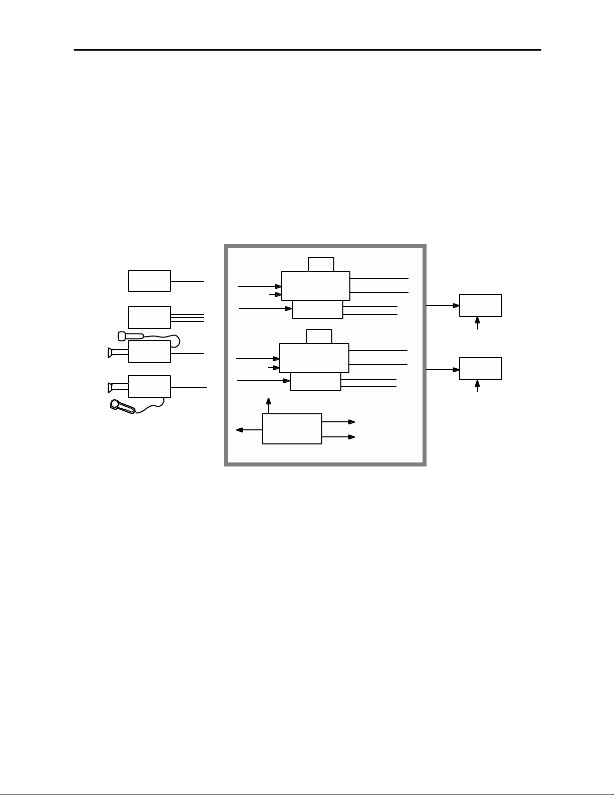
One of three types of Audio Processing submodules can be installed on the 8500 module.
The audio processors have also been designed to provide superior handling of embedded
audio. The disembedder on the input side follows the timing of the SDI input, even if that
input is asynchronous to the house reference. The embedder on the output side is synchronous to house. This allows embedded audio to be safely bypassed around the video
Framestore with the lip sync properly preserved. Embedded audio content is properly resynchronized. The audio processors have built-in sample rate conversion allowing usage of
asynchronous AES inputs, while synchronous AC-3 or Dolby-E audio signals may also be
used.
The 8410 4 Channel Audio Processor shown in the block diagram on the previous page
is a submodule with flexible architecture that addresses a wide range of audio handling
needs. The submodule accepts two external AES audio inputs and one embedded audio
group from the SDI video input. Two outputs can be routed to the AES outputs while four
outputs can also be embedded into the SDI output signal.
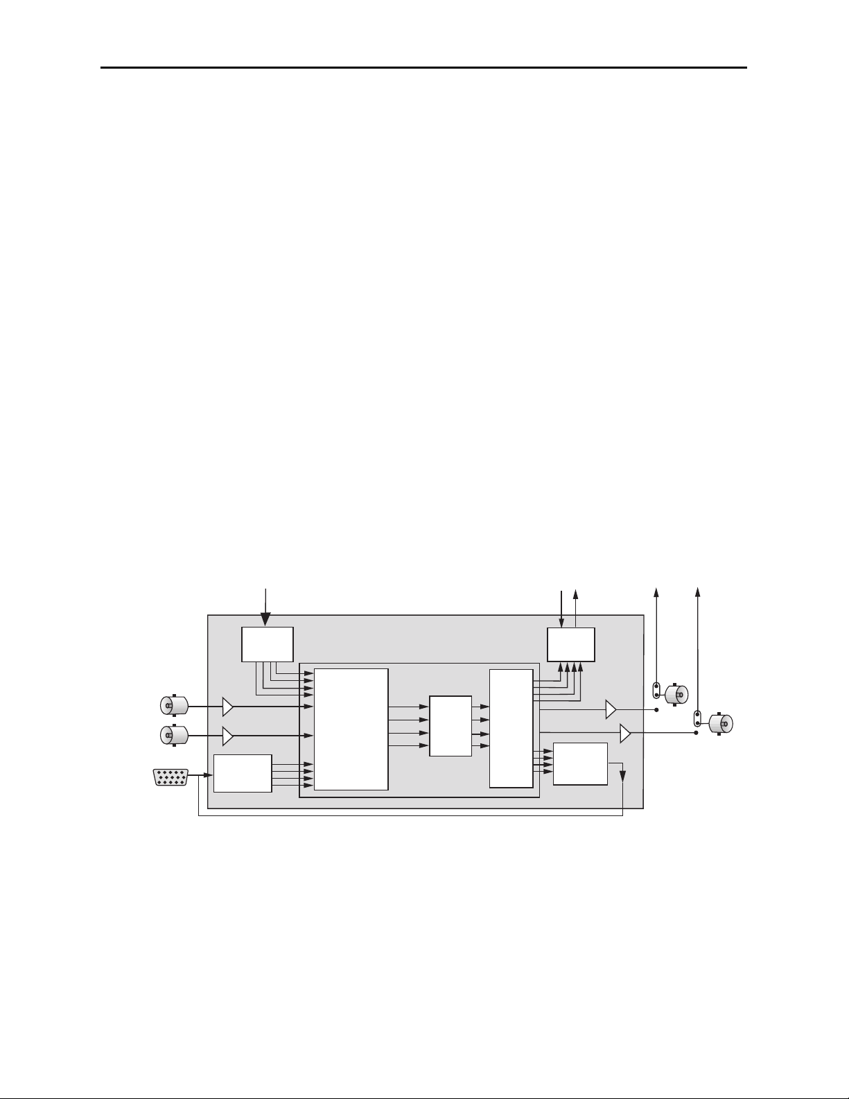
The 8510 4 Channel Audio Processor option shown below can be configured for most
any combination of audio functions the user might desire. There are AES and analog
audio inputs and outputs and the ability to disembed and embed audio on the serial
digital video stream. Disembedded audio or signals from any of the inputs may be mixed,
shuffled or level controlled and any of the channels re-embedded and/or sent to the analog
or AES output connectors. Full audio delay tracking is included as well as the provision to
add fixed delay to correct incoming lip sync errors. There is built in sample rate conversion allowing usage of asynchronous AES inputs, while synchronous AC-3 or Dolby-E
audio signals may also be used. As always, the comprehensive Avenue control system
allows for monitoring and adjustment of all parameters through networked Touch Screen,
Express Panel, or Avenue PC control.
Model 8500 Series Modules
8510 Audio Submodule Block Diagram
8500-4
AES Input
CH 1/2
AES Input
CH 3/4
Analog
Audio I/O
From 8500 SDI Input
Audio
Disembed
4 Channel
24 Bit
ADC
8510 Audio Processor Option
Source Selection
Level Adjust
Swap & Shuffle
Channel Mixing
Auto
Tracking
Audio
Delay
To 8500 SDI Output
Digital
Signal Processing
Output
Routing
Audio
Embed
4 Channel
24 Bit
DAC
SDI/AES
1/2 Out
Switch S4
SDI/AES
3/4 Out
Switch S5
Page 5
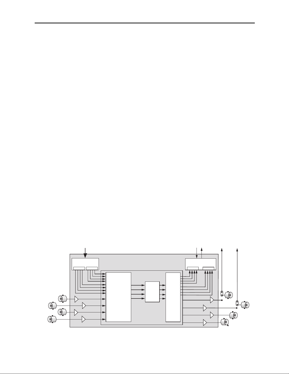
The 8415 Audio Processor submodule shown below provides eight channels of digital
audio processing. Digital audio inputs to the 8415 can come from four AES ports and/or
disembedded from the 601 SDI input stream. After processing, digital outputs in both AES
and embedded form are possible.
There are four AES ports, using the four AES BNC connectors on the rear of the chassis.
When an 8415 is installed, these BNCs become bi-directional ports. Each of them can
either be an AES input or an AES output. These four AES ports are associated with pairs
of channels: Ch 1/2, Ch 3/4, Ch 5/6, and Ch 7/8. A port will become an output if it has not
been chosen as an AES input in the Aud In A and B menus.
There are two disembedders on the input side of the 8415 referred to as A and B. These
disembedders are being fed the 601 SDI video input stream in parallel and each of them
can be independently targeted to any of the four possible groups. The A disembedder will
produce two pairs of audio signals, referred to as SDI 1/2 and SDI 3/4.
The B disembedder will also produce two pairs of audio signals referred to as SDI 5/6 and
SDI 7/8. In the B disembedder, the SDI 5/6 pair corresponds to the first and second
channels in the selected group and SDI 7/8 is taken from the third and fourth channels in
that same group.
The disembedded audio can then be processed with level adjustment, channel mixing,
shuffling, and automatic tracking of the delay imposed on the video channel. It can then
be embedded into the video signal downstream of the the frame synchronizer, proc amp,
and DNR functions on the 8500 module.
There are two embedders referred to as A and B to support the eight channels of audio,
one for each group. The embedders are placed in series with the A embedder first and the
B embedder second. Each embedder must be configured for operating mode and the
desired group (1 – 4) in which to embed the audio. The configuration parameters for the
embedders in the Audio Out menu are not identical. There is no Replace All function for
the B embedder as this function occurs in the upstream embedder A.
(Note that using the 8415 requires Ave PC software version 2.0.4 and higher and the
Control module must be running version 2.0.5 or higher. These versions can be downloaded from the Ensemble website.)
8415 Audio Submodule Block Diagram
Model 8500 Series Modules
8500-5
To 8500 SDI Out
Audio
Embed
B
SDI/AES
1/2 Out
Switch S4
SDI/AES
3/4 Out
Switch S5
Ch 5/6
Ch 7/8
AES Outputs
AES Inputs
CH 3/4
CH 7/8
CH 1/2
CH 5/6
From 8500 SDI In
Dual Audio
Disembed
A A
B
8415 Audio Processor Option
Auto
Source Selection
Level Adjust
Swap & Shuffle
Channel Mixing
Tracking
Audio
Delay
Digital
Signal Processing
Output
Routing
Page 6
Model 8500 Series Modules
8500-6
APPLICATIONS
This section provides some typical applications for utilizing the full versatility of the 8500
Video Processor module and the optional submodules, the 8410, 8415, and 8510 Audio
Processors and the 8520 DNR. Configuration of these applications is covered in the
MODULE CONFIGURATION AND CONTROL section later in this manual.
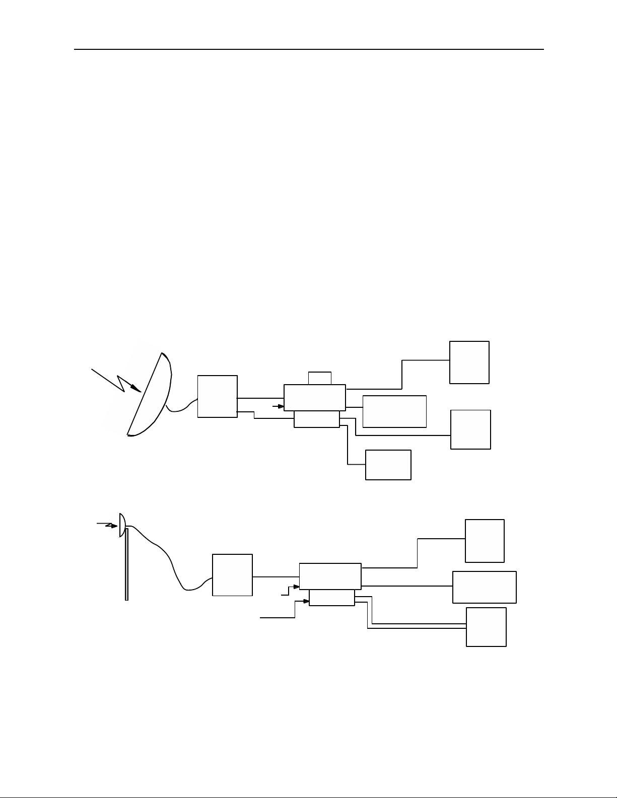
Satellite or Microwave Reception
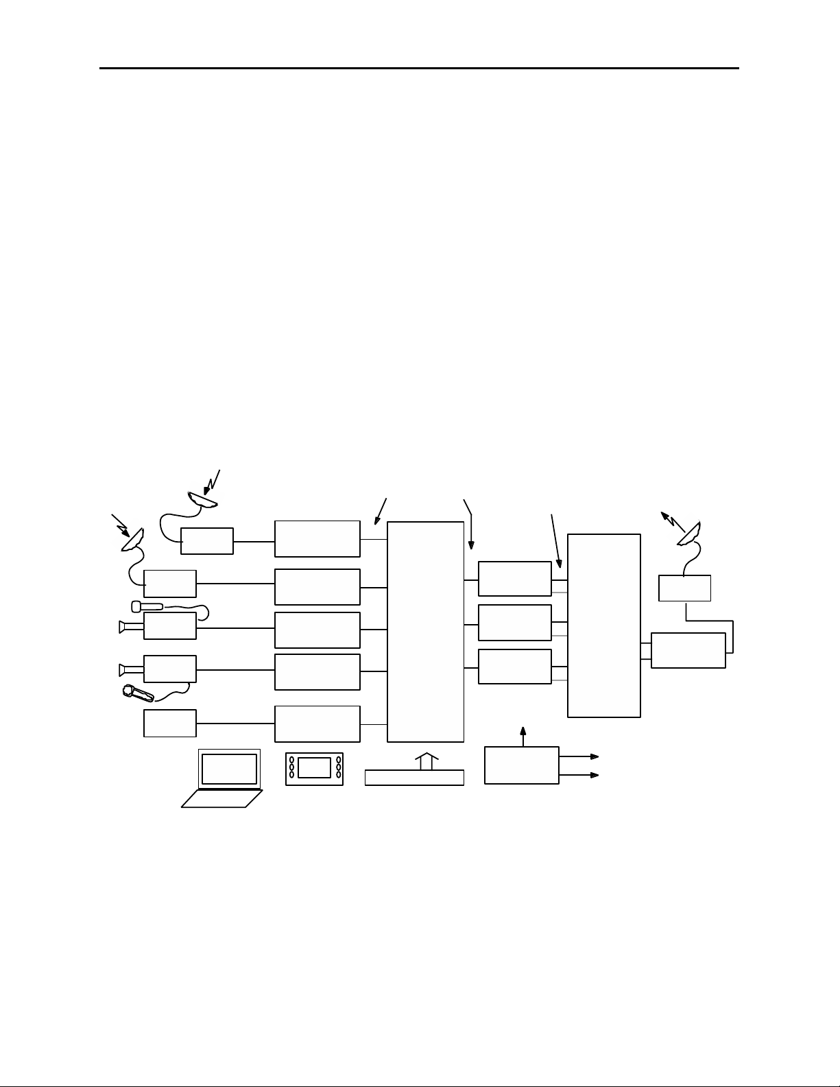
As illustrated in the block diagram below, the 8500 will accept input from either an
analog or a serial digital receiver. Both composite video and SDI signals will now be
locked to house and fully timeable, and are simultaneously available at the output. The
8520 DNR submodule with its Adaptive Motion Detection can be employed to clean up
noisy video.
Proper audio/video timing can be assured when the tracking audio delay of the 8510 Audio
Processor is employed. Any timing or delay modifications to the video are tracked by the
8510 whether you wish to use disembedded audio or audio input from an analog or AES
source. Properly timed audio from any of these sources is available directly when routed
to the analog or AES outputs, or it can be re-embedded back onto the SDI video stream. A
fixed delay of up to 1000mS can be inserted by the 8510 to correct for signals which have
previously passed through frame stores without audio delay compensation.
Satellite or Microwave Application Block Diagram
Satellite
Rcvr
Microwave
Rcvr
Second Language
Analog
Ref
Analog
SDI
Embedded Audio
Ref
Audio AES
8520
DNR
8500 Video Proc
Frame Sync
8510
Audio Proc
8500 Video Proc
Frame Sync
8510
Audio Proc
Analog
Composite Video
Monitoring
Audio
Monitoring
Analog
Disembbedded Audio
nd Language Audio
2
SDI
Both Audios
Reembedded
Analog
Video
AES
SDI
Digital
Production
Switcher
Production
Audio
Digital
Router
Composite
Production
Switcher
Audio
Console
Page 7
Compact Systems
A one rack unit (1 RU) Avenue chassis populated with a 5400 TSG and one or two 8500
Series modules makes an ideal signal acquisition system where small size and light
weight are required. With the variety of input formats which the 8500 Video Processing
Frame Synchronizer accepts, it is equally at home with the Y/C feed from a VHS machine,
Y/Pr/Pb from a BetaCam, composite from an analog camera or SDI from a digital camera.
The 5400 TSG feeds reference to the 8500 to allow stable frame sync operation, as well as
providing analog and SDI reference signals for any of the acquisition equipment, along
with a range of analog and SDI test signals. Video noise reduction is available with the
8520 DNR and the 8510 Audio Processor can provide audio gain control, mixing and
embedding to suit the needs of whatever range of requirements the recorder or microwave
transmitter may have. This example is shown below.
Model 8500 Series Modules
Compact Systems Application Example
8500-7
8520
VHS Player
B Cam
Analog
Camera
Digital
Camera
Analog
Y Pr Pb
Analog
SDI
embedded
Analog
or SDI
Analog
or AES
Analog
or SDI
Analog
or AES
Ref
Ref
Ref
8500 Video Proc
Frame Sync
Audio Proc
8500 Video Proc
Frame Sync
Audio Proc
Ref
5400
Dual TSG
DNR
8510
8520
DNR
8510
SDI embedded
Analog
Analog
AES
SDI embedded
Analog
Analog
AES
Digital and Analog
Test Signals
Analog
Recorder
Ref
Digital
Recorder
Ref
1 Rack Unit Frame
Page 8
Model 8500 Series Modules
News/ENG Vehicle
The wide variety of input feeds often encountered can be easily handled with an Avenue
8500 based system. Inputs are accepted ranging from composite or component video with
analog audio, to SDI with embedded audio, AES audio, or analog audio accompanying the
video stream. Robust signal handling ensures proper time base correction for nearly any
source from a consumer VHS machine to an unlocked portable camera. Proc Amp
functions in the 8500 include video and chroma gain and pedestal, NTSC style hue
rotation and a predictive video signal legalizer. Noisy signals can be cleaned up effectively
with the motion and scene adaptive 8520 DNR. There are operator controls for many
choices including automatic and manual modes. In the manual mode noise reduction
factor is adjustable as is the noise threshold. The show noise and split screen selections
allow viewing of effectiveness of your DNR settings.
Audio is ingested by the 8510 Audio Processor submodule from analog or AES sources
and/or disembedded from the SDI video stream. The internal four channel audio
mixer/router provides level control, mixing of sources and nearly unlimited swap or
shuffle of channels. The 8500 and all other modules may be monitored and adjusted with
the comprehensive Avenue control system. Graphical interface is utilized with the Avenue
PC application running on a laptop or desktop, while the Avenue Touch Screen with touch
and rotary controls can be simultaneously used.
8500-8
News– ENG Application
Satellite
Downlink
Analog
Camera
Digital
Camera
Tape
Player
Helicopter
Analog
Feed
SDI
embedded
Analog
SDI
embedded
Analog
or SDI
PC or Touch Screen Control
of Levels, Inputs, Routing, etc.
8500 Video Proc
Frame Sync
with
8510 and 8520
8500 Video Proc
Frame Sync
with
8510 and 8520
8500 Video Proc
Frame Sync
with
8510 and 8520
8500 Video Proc
Frame Sync
with
8510 and 8520
8500 Video Proc
Frame Sync
with
8510 and 8520
SDI with Embedded Audio
5440
SDI
8x8
Router
X-Y Control Panel
8500 Video Proc
8510 Audio Proc
Analog or SDI with
Embedded Audio, or with
AES or Analog Audio
8500 Video Proc
Frame Sync
with
8510 Audio Proc
Frame Sync
with
8500 Video Proc
Frame Sync
with
8510 Audio Proc
Ref
5400
Dual TSG
Analog
or
Digital
Audio
and
Video
Mixing
and
Routing
Digital and Analog
Test Signals
Satellite
Uplink
SDI
embedded
8500 Video Proc
Frame Sync
with
8510 Audio Proc
Page 9
Model 8500 Series Modules
Remote Truck/OB Van Operation
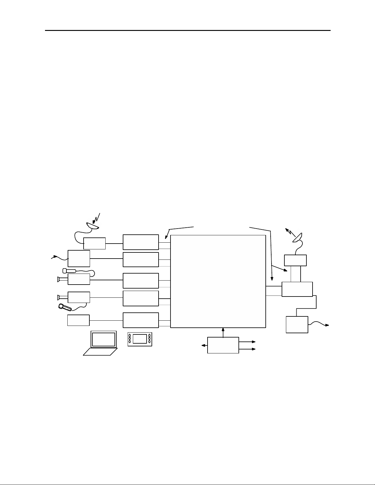
A convenient and flexible interconnect to a Remote Truck or OB Van is assured with use
of the 8500 Video Processing Frame Synchronize (shown below). An 8500 input may be
analog component, composite or SDI, timed to house or asynchronous. Reference is
supplied to the 8500 and outputs are fully timeable in relation to this reference.
Depending upon the needs of a particular shoot, there are both composite and SDI
outputs simultaneously available. The 8520 DNR submodule has Adaptive Motion
Detection and can be employed to clean up noisy video often found in remote situations.
Analog or AES audio inputs are available, or audio embedded on the SDI stream can be
used. Disembedding and re-embedding of audio to the SDI stream is handled by the 8510
Audio Processor option submodule. Most any combination of channel shuffle, mixing and
gain riding can also be done. Audio outputs are simultaneously available at the AES and
analog connectors. The complete range of mix and level control facilities in the 8510
permit these outputs to be the same as the re-embedded audio, or any other combination
of audio channels.
At the output end of the Remote Truck the 8500 is again used to provide a flexible source.
Whether you need the input to be analog or SDI video, analog, AES or embedded audio,
the 8500 will provide a stable feed to microwave or fiber regardless of which audio or
video output formats may be needed.
8500-9
Remote Truck/OB Van Application
Bright Eye
Fiber Rcvr
with
Frame Sync
Analog
Camera
Digital
Camera
Video
Tape
8500 Video Proc
Blimp
Analog
Feed
SDI
embedded
Analog
SDI
embedded
Analog
or SDI
PC or Touch Screen Control
of Input Mode, Proc Functions, etc.
Frame Sync
8510 and 8520
8500 Video Proc
Frame Sync
8510 Audio Proc
8500 Video Proc
Frame Sync
8510 and 8520
8500 Video Proc
Frame Sync
8510 and 8520
8500 Video Proc
Frame Sync
8510 and 8520
SDI or Analog Video with
Analog, Digital or Embedded Audio
with
with
Video and Audio
with
Production Equipment
with
with
5400
Dual TSG
Ref
Digital and Analog
Test Signals
Satellite
Uplink
8500 Video Proc
Frame Sync
with
8510 Audio Proc
SDI
embedded
Bright Eye
Fiber Xmtr
with
Frame Sync
Page 10

8500-10
INSTALLATION
Rear Module BNC Configuration
There are three configurable rear BNC connectors that can be set using onboard switches
on the rear of the 8500 circuit board for the choices outlined below. AES outputs will
depend on the type of submodule installed. Refer to the illustration on the next page.
• Cpst/SDI Out BNC Configuration – The BNC labeled CPST/SDI can be set
with Switch S1 on the rear of the 8500 circuit board for either CPST (up) for a
composite output or to SDI (down) for an SDI output.The default setting for this
switch is CPST when shipped from the factory.
• AES 1/2 Out /SDI Out BNC (8410 and 8510 submodule) or AES 5/6/SDI (8415
submodule) Configuration – Switch S4 on the rear of the 8500 circuit board
allows the BNC labeled AES 1/2 Out/SDI or AES 5/6/SDI BNC to output either
AES audio or the processed SDI signal of the module (identical to the other SDI
outputs). Set the toggle switch to AES to configure the BNC for AES out or set to
SDI for the SDI output. The default setting for this switch is AES.
• AES 3/4 Out /SDI Out BNC (8410 and 8510 submodule) or AES 7/8/SDI (8415
submodule) Configuration – Switch S5 on the rear of the 8500 circuit board
allows the BNC labeled AES 3/4 Out/SDI or AES 7/8/SDI BNC to output either
AES audio or the processed SDI signal of the module (identical to the other SDI
outputs). Set the toggle switch to AES to configure the BNC for AES out or set to
SDI for the SDI output. The default setting for this switch is AES.
8410, 8415, or 8510 Audio and 8520 DNR Submodule Installation
The optional 8500 Series submodules install on the component side of the 8500 Video
Processing module circuit board. If the options are ordered with the 8500 module, they
will come already installed.
To install the 8410, 8415, or 8510 audio submodule, locate the three connectors on the left
side of the circuit board as shown on the next page and line the connectors up, checking
the alignment. Press carefully into place to seat the submodule.
To install the 8520 DNR submodule, locate the UP arrows on the circuit board and the
submodule. Line up the submodule with the two connectors, matching the UP arrows and
press carefully to seat the submodule.
8500 Video Processing Module
Plug the 8500 module into any one of the slots in the 1 RU or 3 RU frame and install the
plastic overlay provided onto the corresponding group of rear BNC connectors associated
with the module location.There are two different plastic overlays provided with this
module. If you are using the 8415 submodule, use the plastic overlay labeled
8500VAP + 8415 8-Channel.
Note that the plastic overlay has an optional adhesive backing for securing it to the
frame. Use of the adhesive backing is only necessary if you would like the location to be
permanent and is not recommended if you need to change module locations. This module
may be hot-swapped (inserted or removed) without powering down or disturbing performance of the other modules in the system.
Model 8500 Series Modules
Page 11
CABLING
Refer to the 3 RU and 1 RU Backplane with 8410 and 8510 Audio Submodule or
3 RU and 1 RU Backplane with 8415 Audio Submodule diagrams on the following
pages for cabling instructions. Note that unless stated otherwise, the 1 RU cabling explanations are identical to those given in the 3 RU diagram.
Configure the three BNCs as described above and follow the correct cabling procedures
depending on how these switches have been configured.
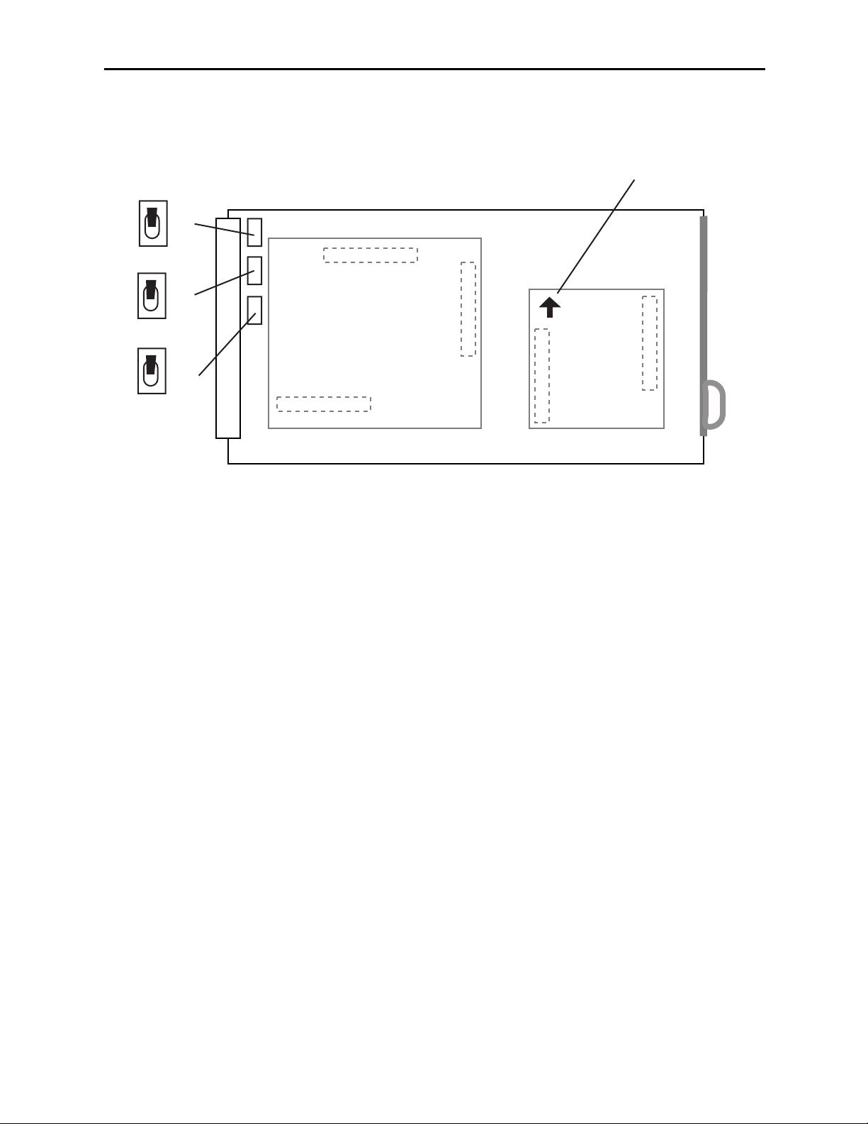
Submodule Installation and BNC Configuration Switches
Model 8500 Series Modules
8500-11
Set toggle switches to configure BNCs on the rear module.
S4 and S5 will depend on the type of audio processor submodule installed.
S1 (Cpst/SDI)
S4 (8410/8510 — AES 1/2 or SDI) or (8415 — AES 5/6 or SDI)
S5 (8410/8510 — AES 3/4 or SDI) or (8415 — AES 7/8 or SDI)
AES
SDI
S5
AES
Match arrows on submodule
and circuit board.
SDI
S4
CPST
SDI
S1
8410, 8415 or
8510 Audio Processor
8520 DNR
Page 12
8500-12
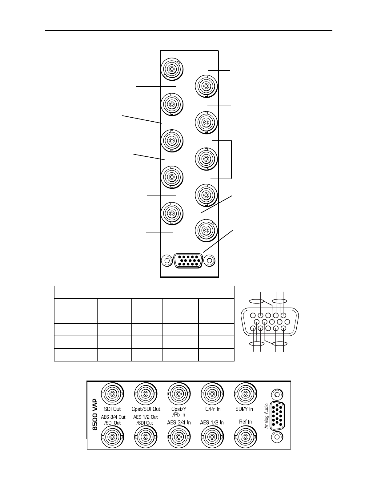
1 RU Backplane With 8410 or 8510 Audio Submodule
AES 1/2 and 3/4 In – Connect
AES digital audio to the AES 1/2
and AES 3/4 inputs.
AES 3/4 Out or SDI Out –
Set BNC to output AES 3/4 audio
or SDI video with toggle switch S5
on circuit board.
Model 8500 Series Modules
Ref In – Connect a composite
video input (PAL or NTSC) if you
are using an external reference.
Cpst/Y/Pb In – Connect the
Cpst (composite), Y (Y/C) or
the Pb (component video) input
depending on the type of video
you are using.
SDI/Y In – Connect an SDI or Y
(component) input depending on
the type of video you are using.
Analog Audio Pinouts
Signal Pins Input Output 2 In/2Out
Aud 1 +, –, G 1, 2, 7 Input 1 Output 1 Input 1
Aud 2 +, –, G 5, 4, 8 Input 2 Output 2 Input 2
Aud 3 +, –, G 11, 12, 9 Input 3 Output 3 Output 1
Aud 4 +, –, G 15, 14, 10 Input 4 Output 4 Output 2
Analog Audio – Use the Analog
Audio 15-pin D connector for
cabling analog audio inputs or
outputs when the 8510 option is
installed. Refer to the pinout
diagram and the table below for
cabling information.
C/Pr In – Connect the C (Y/C) or
the Pr (component video) input
depending on the type of video
you are using.
SDI Out – Connect to an SDI
destination.
Cpst/SDI Out – Set this
connector to output either SDI
or Composite video with switch
S1 on the 8500 circuit board.
3 RU Backplane With 8410 or 8510 Audio Submodule
AES 1/2 Out or SDI Out –
Set BNC to output AES 1/2 audio
or SDI video with toggle switch S4
on circuit board.
8500 VAP
AES 3/4 Out
/SDI Out
SDI Out
AES 1/2 Out
/SDI Out
Cpst/SDI Out
AES 3/4 In
Cpst/Y/Pb In
AES 1/2 In
C/Pr In
Ref In
SDI/Y In
Analog Audio
AUD 2 AUD 1
---
+
+
AUD 4
-
AUD 3
+
1
6
11
+
Page 13
Analog Audio – Use the Analog
Audio 15-pin D connector for
cabling analog audio inputs or
outputs when the 8510 option is
installed. Refer to the pinout
diagram and the table below for
cabling information.
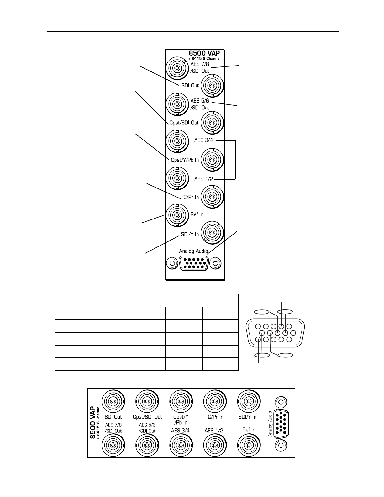
1 RU Backplane With 8415 Submodule
AES 1/2 and 3/4 In or Out –
Use as AES digital audio inputs
or outputs for AES 1/2 and
AES 3/4 inputs.
AES 7/8 In or Out or SDI Out –
Set BNC to input or output AES
7/8 audio or SDI video with toggle
switch S5 on circuit board.
Ref In – Connect a composite
video input (PAL or NTSC) if you
are using an external reference.
Cpst/Y/Pb In – Connect the
Cpst (composite), Y (Y/C) or
the Pb (component video) input
depending on the type of video
you are using.
SDI/Y In – Connect an SDI or Y
(component) input depending on
the type of video you are using.
Analog Audio Pinouts
Signal Pins Input Output 2 In/2Out
Aud 1 +, –, G 1, 2, 7 Input 1 Output 1 Input 1
Aud 2 +, –, G 5, 4, 8 Input 2 Output 2 Input 2
Aud 3 +, –, G 11, 12, 9 Input 3 Output 3 Output 3
Aud 4 +, –, G 15, 14, 10 Input 4 Output 4 Output 4
C/Pr In – Connect the C (Y/C) or
the Pr (component video) input
depending on the type of video
you are using.
NOTE: When the 8415
submodule is installed, the AES
audio BNCs become bi-directional
and can be set as either AES
inputs or outputs in the Aud In
A and B menus.
SDI Out – Connect to an SDI
destination.
Cpst/SDI Out – Set this
connector to output either SDI
or Composite video with switch
S1 on the 8500 circuit board.
3 RU Backplane With 8415 Audio Submodule
AES 5/6 In or Out or SDI Out –
Set BNC to input or output AES
5/6 audio or output SDI video with
toggle switch S5 on circuit board.
Model 8500 Series Modules
8500-13
AUD 2 AUD 1
---
+
+
AUD 4
-
AUD 3
+
1
6
11
+
Page 14

8500-14
MODULE CONFIGURATION AND CONTROL
The configuration parameters for each Avenue module must be selected after installation.
This can be done remotely using one of the Avenue remote control options or locally using
the module front panel controls. Each module has a Remote/Local switch on the front
edge of the circuit board which must first be set to the desired control mode.
The configuration parameter choices for the module will differ between Remote and
Local modes. In Remote mode, the choices are made through software and allow more
selections. The 8500 Parameter Table later in this section summarizes and compares
the various configuration parameters that can be set remotely or locally and the
default/factory settings. It also provides the default User Levels for each control. These
levels can be changed using the Avenue PC application
If you are not using a remote control option, the module parameters must be configured
from the front panel switches. Parameters that have no front panel control will be set to a
default value. The Local switches are illustrated in the Front Panel Controls and
Indicators section following the 8500 Parameter Table. The Local switches are
inactive when the Remote/Local switch is in the Remote position.
In the Remote mode, Avenue module parameters can be configured and controlled from
one of the remote control options, the Avenue Touch Screen, Avenue Express Control
Panel, or the Avenue PC Application. Once the module parameters have been set remotely,
the information is stored on the module CPU. This allows the module to be moved to a
different cell in the frame at your discretion without losing the stored information.
For setting the parameters remotely using the Avenue PC option, refer to the Avenue PC
Remote Configuration section of this document.
For setting the parameters remotely using the Avenue Touch Screen option, refer to the
Avenue Touch Screen Remote Configuration section of this document following
Avenue PC.
Express Panel operation is described in the data pack that accompanies the control panel
option.
Configuration Summary
This section provides a general overview of the configuration for the 8500 module. The
controls available for configuration with remote control are summarized and tips and
examples are given for using particular controls to achieve the best results.
Video Processing
The 8500 has a full-featured Proc Amp for adjustment of every signal parameter. Proc
controls include Video and Chroma Gain, NTSC style hue rotation, Black Balance, and
pedestal. Black and White clips can be set to prevent excessive signal excursions. To help
optimize the settings in the Proc Amp, a Split Screen mode allows you to compare the
processed output with the original material.
Certain values represented in serial digital component may be illegal in the NTSC or PAL
composite domains. The Predictive Composite Clipper mode identifies picture elements
that would be illegal in analog composite, and limits color saturation and luminance
excursions. You can be confident that the work you’re doing in digital component will look
its best in composite.
Model 8500 Series Modules
Page 15

8500-15
Model 8500 Series Modules
A Detail Enhancer recovers information that has been lost due to poor frequency response
in upstream systems.
Selective (toothed) vertical blanking lets you choose to pass or strip content in the vertical
interval on a line by line and field by field basis.
The 8500 has simultaneous SDI and analog composite outputs. They are fully timed to
your house reference, including the subcarrier and ScH phase of the composite output.
The analog output is constructed at 8x oversampling with 12 bits of quantizing resolution.
The available video processing remote control menus are summarized below:
• Proc Menu: Gain, Chroma, Pedestal and Hue are standard Proc Amp controls.
Whether operating with SDI or analog inputs or outputs the Hue control gives
phase rotation of the color vectors in the manner of an NTSC composite Proc Amp.
• Clip: The Legalizer is a predictive clipper which insures signal levels will not
exceed those permitted in the composite domain. Thus its use can insure a television transmitter will not be presented illegal video input. If Off or Legal are
selected other adjustments are grayed and may not be changed. While Legal automatically puts in values to insure signals will not exceed composite legal limits,
selecting Custom allows the operator to insert a range of clip values.
• Filters: The Lum Sharp and Chr Sharp settings allow shaping of the passband for
reduced or added sharpness. With both selections set to Off or Normal there is no
modification of the video. Bandwidth reduction can be useful in reducing artifacts
when using the 8500 for preprocessing of signals which will receive MPEG compression, while adding sharpness may benefit signals which arrive at the input
with reduced bandwidth.
• Timing: The 8500’s comprehensive range of timing allows complete flexibility in
placement of the output picture relative to the applied reference input. Fine Phase
and Hor Timing take the horizontal timing across the entire line with nanosecond
accuracy. A Vert Timing adjustment completes the range in allowing any output
timing desired by the operator.
• Status: This dynamic monitoring display provides indicators of video and audio
inputs and EDH error status. Options such as the 8510 Audio Processor and 8520
DNR show in the Option window when present.
• Trims: Cb and Cr offsets allow black balance to be corrected while Cb and Cr
gains permit trimming of levels on these two axes. Y/C delay allows the operator to
correct inaccuracy of timing of color information relative to luminance. These trims
are functional regardless of the input or output formats in use.
• Output: The Bypass selection takes the 8500 Proc Amp out of the video path by
routing the signal around it to output. Split mode may be used to compare input
and output signals to observe the effect of adjustments. Note that these are "live"
modes and the bypassed or split video will be fed on downstream to following
equipment. Embedded Audio is removed from the SDI stream when Strip is
selected in the Strip Audio window. Normal four field Color Lock is ordinarily used,
though other color locking modes may be selected to fit specialized needs.
Page 16

• Blanking: There are Wide, Narrow or Custom blanking choices. Wide gives
blanking through line 20 (NTSC) or line 22 (PAL), while narrow produces blanking
through line 9 (NTSC) or Line 6 (PAL) of both fields. In the Custom mode any individual lines from 9 through 23 may be selectively blanked, with different choices
allowed for each field. Some systems recognize position of the V-bit to control end
of blanking. In the 525 standard V-bit position can be set to line 10, line 20 or line
23. In 625 mode V-bit is fixed at line 23 as this is the only position permitted by
the 625 Standard.
• Memory: Up to five configurations of the 8500 may be saved into memory
registers for later recall. All parameters – gains, input format, filters, blanking, etc.
- are saved in each memory. The 8500 for SDI Input can be used with audio disembedding, channel swapping and re-embedding in a particular application. In
another application it is used with composite input, noise reduction and embedding
of audio from an analog audio input source. These two setups could be stored in
memory registers and one or the other recalled for instant restoration of the
required configuration.
8500-16
Model 8500 Series Modules
Page 17

8410, 8415, and 8510 Audio Processor Configuration
The 8510 Audio Processor will accept audio from analog or AES input connectors and can
disembed audio from the incoming SDI video stream. The 8410 does everything the 8510
does, except that it has no analog audio I/O. The 8415 Audio Processor accepts audio from
the AES input connectors and can disembed audio from the incoming SDI video stream.
Between the input and output is a 4x4 audio mixer (8x8 mixer with the 8415) with
tracking audio delay. Any incoming audio can be mixed, level controlled and/or shuffled to
another output channel by means of the integrated audio router. The tracking audio delay
allows synchronization and timing to be maintained with time base corrected video
passing through the video frame synchronizer of the 8500.
A built in sample rate converter allows use of asynchronous AES input signals. The Audio
Processors also support encoded audio formats such as AC-3 and Dolby-E. Because these
data streams cannot tolerate sample rate conversion, they must be input to the Audio
Processors synchronous to the video. All audio processing is performed at the full 24 bit
resolution of the system. At the output side of the submodule the four audio channels
(eight channels with the 8415) may be simultaneously routed to analog (8510 only) and
AES output connectors while also being embedded on the outgoing SDI video. An adapter
is also available to allow the AES I/O to be converted from BNC to 110 ohm balanced.
The available audio processing remote control menus are summarized below:
• Audio In: Status indicators show presence of AES and embedded (SDI) audio
inputs. The In 1/2 Sel and In 3/4 Sel controls provide for selection of inputs to the
audio mixer. The choices for the 8410 and 8510 are AES 1/2, Anlg 1/2, SDI 1/2,
AES 3/4, Anlg 3/4, and SDI 3/4. The 8415 has four additional choices, AES 5/6 and
7/8 and SDI 5/6 and 7/8. Thus any pair of input audio signals can be routed to
either pair of input buses of the output audio mixer. As well (8510 only) the anticipated nominal level of this incoming audio can be set with the Anlg Lvl controls.
• Audio Mode: The Audio Mode control is provided to allow an SDI input with
embedded audio to operate in Audio (normal) or Data (non-audio). The 8500 can
handle both types of content present in AC-3 or Dolby_E signals. Some synchronizing requirements are necessary for supporting these protocols.
Select the Audio mode when the input audio signal is a standard audio signal
carrying two channels of linear audio. No special timing requirements are needed
in this mode.
Use the Data mode when the serial digital audio is a non-audio, or data, signal.
Some special synchronizing requirements must be observed in this mode as
described in the following examples.
SDI Signal with embedded data – For this case, if an SDI signal with
embedded data is applied to the input, the content will be handled by
passing through the 8500 frame store memory to the output of the 8500.
No audio submodule is required.The audio input signal in this case is synchronous to the timing reference. This is normal operation of the 8500 and
no special configuration is necessary.
Data mode signal to be disembedded and output as an AES stream –
This mode requires the use of an audio submodule to disembed the de-serialized SDI input and route the channels to the correct path. If one of the
channels is normal audio, it can be mixed, swapped, shuffled, and delayed
by the audio submodule. If the other channel is non-audio data, it bypasses
8500-17
Model 8500 Series Modules
Page 18

the normal audio functions and is carried to the AES output formatter and
driver.
When in the Data mode, the AES formatter is driven by the output timing
of the 8500, the original SDI input must be synchronous to the reference
input or the 8500 must be configured to use the SDI signal as the timing
reference.
Data mode signal to be disembedded, output as AES, then reembedded – In this case the audio submodule is also required. This case is
similar to the one above, while the disembedded data is re-embedded in the
SDI output of the 8500. The same timing requirements apply.
Original embedded data to be left unchanged with an additional
embedded group to be added – The original embedding in the SDI input
passes through the 8500 processing path. At the same time, an audio
submodule is used to create a second embedded group which is placed in
cascade, following the original audio group which contains the data mode
signal.
A data mode signal in AES format is input to the audio submodule –
This example could be used when there is a need to embed the AES data
into the output of the 8500. In this case the AES data input must be synchronous. When being used in this manner, the audio submodule can embed
data mode AES into one pair of channels in an embedded group, while
embedding conventional audio into the other pair.
• Audio Mix: This menu gives full access to the 4x4 or 8x8 audio mixer controls.
Any input channel can be routed to any or all output busses. Sliders or Touch
Screen rotary knobs permit levels to be adjusted from -70dB to +12dB.
Alternatively a value can be put in the numeric window, followed by the Enter key,
and this will become the new gain setting. Default buttons are provided for return
to zero level.
The Tie function is used for stereo operation where gain of a pair of channels is
usually desired to be the same. An invert selection allows inversion of a channel to
permit phase correction.
• Audio Delay: With the Auto Track switched On, audio will be delayed the same
amount as the video passing through the 8500 frame synchronizer thus preserving
lip sync. If incoming audio is early due to signals passing through an upstream
frame sync without a compensating audio delay, Bulk Delay can be used to correct
the problem. Up to 1000 mS of fixed delay can be added to compensate for
upstream timing errors.
8500-18
Model 8500 Series Modules
Page 19

Audio Operational Examples
This section describes the audio configuration of the application examples given at the
beginning of this manual. Both the 8410 and 8510 have AES I/O and handle embedded
audio. For analog audio, an 8510 is required.
Audio Example 1: Let’s assume stereo analog audio is arriving from a satellite receiver
(not AES,as shown in the Satellite block diagram). We want to embed this audio on an
outgoing SDI video stream and also provide analog audio for monitoring. In addition we
wish to provide audio for use in an audio console with AES inputs. Tracking audio delay
will be used to maintain proper lip sync. We’ll be using an 8500 with an 8510 submodule.
1. Bring the analog audio into channels 1 and 2. Refer to the connector drawing for
pinout of the 15 pin D connector in the Cabling section.
2. With the In 1/2 Sel choose Anlg 1/2 as the source for channels 1 and 2 of the 4x4
audio mixer.
3. Set Anlg 1 Lvl and Anlg 2 Lvl to the nominal level of the incoming audio.
4. In the Audio Mix menu Select Ch1 for Output Bus 1 and Ch2 for Output Bus 2.
The mixer output buses automatically appear on the designated output pins of the
15 pin D connector in analog form, and on the AES output BNC’s as AES audio.
5. Select Embed On to embed the audio on to the SDI video output stream.
6. In the Aud Delay menu turn On the Auto Track so audio delay will track the video
timing.
Audio Example 2: Consider a situation where there is embedded stereo audio on
channels 1 and 2 of the incoming SDI video. A second language stereo feed comes in on
AES channels 1 and 2 as shown in the Microwave block diagram but the level is 4 dB
higher than desired.
1. SDI 1/2 is selected with the In 1/2 Sel so as to feed this audio to channels 1 and 2
of the 4x4 audio mixer.
2. AES 1/2 is selected with the In 3/4 Sel thus bringing the second audio information
into channels 3 and 4 of the 4x4 audio mixer.
3. Tie is selected and the channel 3 and 4 faders set to -4dB to correct the incoming
level discrepancy.
4. All 4 channels are then re-embedded on the outgoing SDI video by selecting Embed
On.
These same 4 channels are also available as 4 analog outputs and AES output channels.
It is now possible to monitor audio using the analog outputs from an 8510 while feeding
the AES outputs to a digital audio mixer for further usage.
8500-19
Model 8500 Series Modules
Page 20

Audio Example 3: Here stereo audio embedded on an SDI stream is arriving via
microwave, but lip sync is off by about 65mS due to video passing through upstream
frame stores. We wish to synchronize to house reference and add monaural analog background music to the audio, then re-embed it back into the SDI video stream.
1. SDI 1/2 is selected with the In 1/2 Sel so as to feed the disembedded audio to
channels 1 and 2 of the 4x4 audio mixer.
2. In the Audio Mix menu, select Ch1 for Output Bus 1 and Ch2 for Output Bus 2.
3. Anlg 3/4 is selected with the In 3/4 Sel. The monaural music is fed to channel 3
input with the channel 3 fader set to -10dB for proper background music level.
4. Channels 1 and 2 are selected for Output Bus assigns on this mixer so as to
produce the desired background music mix for re-embedding.
5. A Bulk Delay of 65mS is used to correct for the upstream error.
6. Select Embed On to embed the audio on to the SDI video output stream.
7. Auto Track is set to the On state so the tracking audio delay will the match delay
of the video frame synchronizer thus producing proper delay and correct lip sync.
8500-20
Model 8500 Series Modules
Page 21

8520 Digital Noise Reducer Configuration
The 8520 DNR is motion and scene adaptive. It removes unwanted noise and artifacts,
making it perfect for MPEG compression preprocessing and satellite or ENG feeds.
Several forms of noise reduction are employed to ensure the best possible performance.
Recursive Temporal Noise filtering includes Simple Recursive, Motion Adaptive and
Motion Adaptive with Impulse filter. Controls are provided for maximum signal to noise
improvement and for noise threshold. These can be set manually or run in automatic
mode.
Motion Adaptive Recursive Noise filtering works on a pixel by pixel basis, comparing the
current frame to frames that have already been filtered. If the change that is detected is
small, it is considered noise, while if it is large, it is considered motion or a scene change.
The detection process uses an LMMSE (Linear Minimum Mean Square Error) filtering
algorithm to evaluate the presence of motion. Combining this algorithm with recursive
temporal filters preserves fine detail while reducing noise in the presence of motion,
including rapidly moving objects and scene changes. Motion trails are minimized while
avoiding hard motion failures that some adaptive noise filters can exhibit.
The DNR menu gives six choices of operating mode:
1. Automatic Lo: A good setting for most material. Noise is reduced and the NR
Factor and Threshold displays will be seen to change dynamically with video
content. A moderate amount of noise is removed with few motion artifacts
produced.
2. Automatic Hi: NR Factor and Threshold receive enhanced values for greater
noise reduction with somewhat increased chance for motion artifacts to appear.
3. Adaptive: This manual setting allows the operator full control of all settings. A
better mix of noise reduction vs motion artifacts is possible but, being a manual
mode, it may not be possible for the operator to react optimally to changing scenes.
4. Adaptive/Impulse 1: Same as Adaptive with the addition of an impulse filter for
removal of large, narrow amplitude noise pulses.
5. Adaptive/Impulse 2: Same as Adaptive with the addition of an impulse filter for
removal of a wider bandwidth of noise. More softening of detail will be seen.
6. Non Adaptive: For still pictures, can be set for optimal noise reduction.
A special Luma Tie mode reduces dot crawl artifacts from composite originated material
by identifying cross-color and cross-luminance effects as unwanted noise.
The Show Noise output mode displays what areas of the picture are being affected by the
noise reducer. Noise is represented by white or black, while unaffected areas are represented in gray. This handy mode makes it easy to set optimum adjustments for the
material being processed. The Split Screen mode lets you compare the processed output to
the original signal.
8500-21
Model 8500 Series Modules
Page 22

8500-22
Model 8500 Series Modules
8500 Parameter Table
CONTROL LOCAL REMOTE
FACTORY
DEFAULT
DEFAULT
USER LEVEL
VIDEO IN/PROCESSING CONTROLS
Input Select
Switch 1:
SDI or Analog
If Analog:
Switch 2:
Cpst or CAV
If CAV:
Switch 3:
Beta or SMPTE
Composite
Compst No Setup
Y_C
Y_C No Setup
Beta
Beta No Setup
SMPTE
Serial
Composite Level 1
Comb Mode 3 Line
3 line
5 Line
3 Line Level 1
Reference Source
Switch 4: TBC
On (ext ref) or
Off (self ref)
Ext Ref
Master Ref
Video In Ref
Ext Ref Admin
Gain 100% 0 – 150% 100% Admin
Chroma 100% 0 – 150% 100% Admin
Pedestal 0 IRE +/– 30 IRE 0 IRE Admin
Hue 0 IRE +/– 180 degrees 0 degrees Admin
Legalizer
Switch 5:
On or Off
Off
Legal
Custom
Off Admin
B/W Clip Off
Off
On
Off Admin
Black Clip –8 IRE –8 to 6.2 IRE –8 IRE Admin
White Clip 110 IRE 95 – 110 IRE 110 IRE Admin
Chr CLip Mode Off
Off
Chroma
Cpst
Off Admin
Chr Lo Clip –40 IRE –40 to 7.5 IRE –40 IRE Admin
Chr Hi Clip –140 IRE 100 – 140 IRE 140 IRE Admin
Page 23

Model 8500 Series Modules
CONTROL LOCAL REMOTE
FACTORY
DEFAULT
DEFAULT
USER LEVEL
DNR CONTROLS (8520 DNR submodule installed)
DNR Mode
Switch 6:
On (Automatic
Lo) or Off
Automatic Lo
Automatic Hi
Adaptive
Adapt/Impulse1
Adaptive/Impulse2
Non Adaptive
Automatic Lo Admin
DNR Bypass Normal
Normal
Bypass
Show Noise
Normal Admin
DNR Luma On
Off
On
Luma Tie
On Admin
Luma NR Factor 6 dB 0 – 20 dB 6 dB Admin
Luma Threshold 25 dB 0 – 25 dB 25 dB Admin
DNR Chroma Off
Off
On
Off Admin
Chroma NR Factor 6 dB 0 – 20 dB 6 dB Admin
Chroma Threshold 25 dB 0 – 25 dB 25 dB Admin
FILTER CONTROLS
Chr Sharp Off
Max
1/2
1/4
Off
Off Admin
Luma Sharp Off
Max
1/2
1/4
Off
Off Admin
TIMING CONTROLS
Fine Phase 0 ns +/– 40 ns 0 ns Admin
Horizontal Timing 0 clocks +/– 1716 clocks 0 clocks Admin
Vertical Timing 0 lines +/– 525 lines 0 lines Admin
8500-23
8500 Parameter Table (Continued)
Page 24

Model 8500 Series Modules
8500-24
CONTROL LOCAL REMOTE
FACTORY
DEFAULT
DEFAULT
USER LEVEL
VIDEO OUTPUT CONTROLS
Bypass Normal
Normal
Bypass
Split
Split DNR
Normal Admin
Strip Audio Off
Off
On
Off Admin
Color Lock Normal
2 Field
Normal
Field 3
Field 5
Field 7
Normal Admin
Setup Off
Off
On
Off Admin
Test Pattern Off
Off
Bars
Black
Pathological
Off Admin
Signal Mute No Muting
No Muting
Mutes on Noise
Freeze on Noise
No Muting Admin
BLANKING and TRIM CONTROLS
Mode Narrow
Narrow
(PAL Lines 1-6<
NTSC Lines 1-9)
Wide
(PAL Lines 1-22<
NTSC Lines 1-20)
Custom
Wide Admin
V Bit Position Line 20
Line 10
Line 20
Line 23
Line 20 Admin
Field 1/2 Toothed
Blanking
N/A
< 9, 9, 10, 11, 12,
13, 14, 15, 16, 17,
18, 19, 20, 21, 22,
23
Level 2
Cb Offset 0 IRE +/– 300 IRE 0 IRE Admin
Cr Offset 0 IRE +/– 300 IRE 0 IRE Admin
Cb Gain 0 IRE +/– 20 IRE 0 IRE Admin
Cr Gain 0 IRE +/– 20 IRE 0 IRE Admin
8500 Parameter Table (Continued)
Page 25

CONTROL LOCAL REMOTE
FACTORY
DEFAULT
DEFAULT
USER LEVEL
AUDIO CONTROLS (8410, 8415 or 8510 Audio Submodule Installed)
Ch 1-4 In (level) –70 dB –70 to +12 dB –70 dB Level 1
Ch 1-4 Output Bus
Ch 1 – Output 1
Ch 2 – Output 2
Ch 3 – Output 3
Ch 4 – Output 4
Output Bus 1 – 4
Ch 1 – Output 1
Ch 2 – Output 2
Ch 3 – Output 3
Ch 4 – Output 4
Tie
Level 1
1/2 Input
Switch 7:
Anlg or Dig
If Dig:
Switch 8:
AES or Embed
AES 1/2
Anlg 1/2
SDI 1/2
AES 3/4
Anlg 3/4
SDI 3/4
Anlg 1/2 Level 1
3/4 Input
AES 1/2
Anlg 1/2
SDI 1/2
AES 3/4
Anlg 3/4
SDI 3/4
Anlg 3/4 Level 1
5/6 and 7/8 Input
(8415 only)
Switch 8:
AES or Embed
AES 1/2
AES 3/4
AES 5/6
AES 7/8
SDI 1/2
SDI 3/4
SDI5/6
SDI 7/8
AES 5/6
AES 7/8
Level 1
1/2, 3/4, 5/6, 7/8
Mode
Auto
Audio
Data
Auto
Auto Level 1
DeMux Group Group 1
Group 1
Group 2
Group 3
Group 4
Group 1 Level 1
Anlg In Level +4 dB
–10 dB
–6 dB
–4 dB
0 dB
+4 dB
+4 dB Level 1
Auto Track On
Off
On
On Level 1
Bulk Delay 0 msec 0 – 1000 msec 0 msec Level 1
8500 Parameter Table (Continued)
Model 8500 Series Modules
8500-25
Page 26

CONTROL LOCAL REMOTE
FACTORY
DEFAULT
DEFAULT
USER LEVEL
AUDIO CONTROLS (8410, 8415 or 8510 Audio Submodule Installed)
Audio Embed Replace
Off
Replace
Cascade
Replace Level 1
Mux Group
(Mux Group A and B
for the 8415)
Group 1
Group 1
Group 2
Group 3
Group 4
Group 1 Level 1
Anlg Out Level
(8510 only)
+4 dB
–10 dB
–6 dB
–4 dB
0 dB
+4 dB
+4 dB Level 1
Dig Ref Level –20 dBFS
–20 dBFS
–18 dBFS
–20 dBFS Level 1
8500 Parameter Table (Continued)
Model 8500 Series Modules
8500-26
Page 27

Front Panel Controls and Indicators
Each front edge indicator and switch setting is shown in the diagram below:
Remote/Local switch:
Set to the mode you
will be using.
Pwr green LED:
Indicates the presence (ON) or
absence (OFF) of power (+5V).
Run green LED:
OFF:
A power fault or halted CPU
ON:
A halted CPU
FAST BLINK:
CPU Run error
SLOW BLINK:
System OK. (If SPI control
is active from the main
frame System Control
Module, all Run indicators
will be synchronized.)
Input green LED:
On indicates input video signal
is present and detected.
OFF no input video signal
detected on the input.
Ref green LED:
On when the selected reference
source is detected.
OFF when no reference signal is
detected.
Aud Pres
green LED:
On when analog audio input is
detected on the module audio
input.
OFF when no analog audio is
detected.
SDI/Analog switch:
Select SDI or Analog depending on
the video input signal format to the
module.
Cpst/CAV switch:
For an analog video input selected
above, select Cpst or CAV.
Beta/SMPTE
switch:
For an analog CAV input selected
above, select Beta or SMPTE.
TBC switch:
Turn time base corrector (external
reference) On or Off.
Legalizer
switch:
Turn On to enable legalizer or OFF
to disable.
DNR
switch:
Select On to enable DNR processing
or Off to disable the DNR.
Anlg/Dig
switch:
Select Anlg or Dig to identify what
audio format is being input to the
module.
AES/Embed switch:
When switch above is set to Dig,
select AES or Embed to identify
what type of digital audio is being
input to the module.
EDH Err red LED:
On when EDH is present and
CRC errors are detected.
OFF when EDH is not present or
CRC errors are not detected.
AES In 1/2
green LED:
On when an AES input is
detected on the AES 1/2
audio input.
OFF when no audio is
detected on AES 1/2.
Embed
Aud green LED:
On when an audio ancillary packet
is detected in the serial stream.
OFF when no audio ancillary
packet is detected.
AES 3/4 green LED:
On when an AES input is
detected on the AES 3/4
audio input.
OFF when no AES audio is
detected on AES 3/4.
Model 8500 Series Modules
8500-27
Page 28

Avenue PC Remote Configuration
The Avenue PC remote control menus for this module are illustrated and explained below.
Refer to the 8500 Parameter Table for a summary of available parameters that can be
set remotely through the menus illustrated. The Configuration Summary gives tips
and general background information on setting the parameters. For more information on
using Avenue PC, refer to the Avenue PC Control Application Software data pack.
Parameter fields that are grayed out can indicate one of the following conditions:
• An option is not installed.
• The function is not active.
• The module is locked.
• The User Level set with Avenue PC is not accessible from the current User Level.
NOTE: Different audio menus will appear when an 8415 Audio Processor
submodule is installed. The differences in menu structure will be explained in this
section.
8500 Avenue PC Menus
The Vid In menu shown below allows you to configure the following input sources:
• Input Sel – use this control to set the video input mode connected to the module.
• Ref Source – use this control to set the reference input source.
• Comb Mode – set the type of comb filter (3- or 5-line) for the video input.
Status reporting is provided for the following conditions:
• Input – reports the input status as No Input, 525 Lock, or 625 Lock.
• EDH Status – reports the presence of EDH, EDA, and IDA errors.
• Error Seconds – displays the number of seconds that a detected EDH error has
been present in the serial data stream.
• Reference – reports the status of the reference input as either No Reference,
Ref Mismatch, Ref Unlocked, Ref 525 Lock, or Ref 625 Lock.
8500-28
Model 8500 Series Modules
Page 29

Model 8500 Series Modules
The Proc menu shown below allows you to adjust the following video processing parameters for the signal:
• Gain – adjust the percentage of overall gain (luminance and chrominance).
• Chroma – adjust the percentage of chroma amplitude.
• Pedestal – adjust the pedestal (black) level of the signal in IRE.
• Hue – adjust the hue of the signal ± 180 degrees.
8500-29
Page 30

Use the Clip menu shown below to adjust the following parameters:
• Legalizer – set the legalizer function to one of the following:
Off – to disable it.
Legal – to apply the following factory default values:
• B/W Clip is on.
• Black Clip is set to 2.5 IRE.
• White Clip is set to +105 IRE.
• Chr Clip Mode is predictive composite.
• Chr Lo Clip is set to –20 IRE.
• Chr Hi Clip is set to +120 IRE.
Custom – to enable the B/W Clip and Chr Clip Modes controls to set custom
parameters with the following controls:
• B/W Clip – select On to enable black and white clip functions or Off to
disable them.
• Black Clip – set the threshold for the black clip level. (No content
will be allowed below the level set.)
• White Clip – set the threshold for the white clip. (No content will be
allowed above the level set.)
• Chr Clip Mode – select one of the following modes:
• Off for no chroma clip functions.
• Chroma to use the chroma clip controls Chr Lo Clip/Chr Hi Clip
to set to clip the chroma content (irrespective of the luminance).
• Cpst to enable the Predictive Composite Clipper. This mode allows
you to ensure that when the signal is encoded to PAL or NTSC, the
minimum and maximum chroma excursions do not exceed preset
levels. Because in composite video, the chroma rides on the
luminance, this clip mode is based on chroma and luminance values.
Model 8500 Series Modules
8500-30
Page 31

The DNR menu allows you to adjust the following noise reducer parameters for the signal
when the 8520 DNR submodule is installed:
• Mode – set the mode of noise reduction based on the type of noise and the amount
of motion in the signal. Set the Mode to one of the following:
Automatic Lo – this setting is completely automatic and requires no user
adjustments. The adjustments for Noise Reduction (NR) and Threshold
change depending on the source material. Luma and Chroma filters and
Chroma/Luma tie controls are shown in the figure below. This mode uses
the Impulse 1 filter that removes a moderate amount of noise and shows
little motion artifacts. It is most useful for signals that vary a great deal
and require less operator intervention.
Automatic Hi – this setting is also completely automatic and requires no
user adjustments. The adjustments for enhanced noise reduction (NR) and
Threshold. Luma and Chroma filters and Chroma/Luma tie are on. This
mode uses the Impulse 2 filter (also temporal). All noise is removed in this
mode and chances are higher for motion artifacts to appear.
8500-31
Model 8500 Series Modules
Page 32

Adaptive – this mode requires manual settings of all parameters. Fine
detail is preserved and motion is removed. Best used for signals with less
motion and results viewed with the Show Noise function and a waveform
monitor. The Adaptive controls are shown in the figure below.
Adapt/Impulse 1 – this mode is similar to the Adaptive mode above but
adds an Impulse 1 filter control for removal of impulse noise — large,
narrow amplitude noise with a very high bandwidth (narrow). This filter
requires detail to be very fine before it will be removed. It is best for
removing fine sparkles in the video. Some fine moving details, such as rain,
can soften and blur with this filter enabled and so is not recommended for
this type of scene.
Adapt/Impulse 2 – this mode is similar to the Adaptive/Impulse 1 mode
above but adds an Impulse 2 filter control. This allows removal of a wider
bandwidth of impulse noise. As a result, scenes with bigger detail will be
affected. This is also an effective filter for removing sparkles but blurring
and softening of detail will be more obvious than the Impulse 1 filter.
Non Adaptive – this filter is the most effective for still pictures. Noise
reduction can be set to the highest level with the luma and chroma NR and
threshold controls to produce the best results. Not recommended for
pictures with any motion.
Model 8500 Series Modules
8500-32
Page 33

• Luma – set to On to enable the Luma control or Off to disable. The luma channel
can be adjusted independently of the chroma channel for noise reduction and
motion threshold while in any of the Motion Adaptive Recursive modes.
• Use the Luma NR Factor and Threshold controls to fine tune the noise as
it appears on a waveform monitor and the Show Noise function set in the
Bypass mode below.
• Chroma – set to On to enable the Luma control or Off to disable. The noise
reduction and threshold of the chroma channel can be adjusted independently of
the luma channel with these controls. A Luma Tie setting is provided that controls
the chroma filter based on the motion estimation on the luma channel. Not only is
noise more effectively reduced when this control is active, but it can also reduce the
appearance of cross-color artifacts from poor upstream decoding of composite
signals.
• Use the Chroma NR Factor and Threshold controls to fine tune the
chroma noise factor.
• Bypass – set the DNR output mode in conjunction with the Vid Out menu Bypass
function with this control. You may use this control to view the desired DNR
output for comparing noise reduction or detail enhancement. Refer to the Vid Out
menu for details on setting this mode.
8500-33
Model 8500 Series Modules
Page 34

8410 and 8510 Audio Processor Submodules
When an 8410 or 8510 Audio Processor submodule is installed, use the Aud Mix menu
shown below to control the audio mixing and shuffling of the module. Each output bus
assignment will be indicated by a green box.
• Input Ch 1 – assign Input Channel 1 to the desired output bus or tie to
Channel 2. Set the input level using the slider control or by entering a number in
the window and pressing the Enter key on your PC.
• Input Ch 2 – assign Input Channel 2 to the desired output bus or tie to
Channel 1. Set the input level using the slider control or by entering a number in
the window and pressing the Enter key on your PC.
• Input Ch 3 – assign Input Channel 3 to the desired output bus or tie to
Channel 4. Set the input level using the slider control or by entering a number in
the window and pressing the Enter key on your PC.
• Input Ch 4 – assign Input Channel 4 to the desired output bus or tie to
Channel 3. Set the input level using the slider control or by entering a number in
the window and pressing the Enter key on your PC.
Selecting the Tie button in Input Ch 1 or Input Ch 2 will tie the two controls together.
Selecting the Tie button in Input Ch 3 or Input Ch 4 will tie the controls for these
channels together.
Select the Default button to return to the default value.
Select the Invert button to invert the phase of the audio content.
Model 8500 Series Modules
8500-34
Page 35

Use the Aud In menu shown below for the 8410 and 8510 to adjust the following parameters:
• 1/2 Input – select the input audio source for Input 1/2.
• 3/4 Input – select the input audio source for Input 3/4.
• 1/2 Mode – for a Serial input with embedded audio, select the type of audio in the
stream:
• Audio – the embedded stream is standard audio.
• Data – the embedded stream is a non-audio signal.
• Auto – the module will detect the type of signal embedded in the stream,
audio or data.
• 3/4 Mode – select the type of audio in the serial stream as described above.
• DeMux Group – select the embedded audio group to demultiplex from the selections. The status of embedded audio is shown in the Embed In view.
• Anlg In Lvl (8510 only)– set the nominal level of the analog audio input.
Setting analog levels: For example, if the nominal level of your incoming analog audio is
+4 dB, set the Anlg In Lvl to +4 dB (8510 only).
The status of the corresponding audio inputs are shown next to the control. Status is
reported as one of the following:
• Analog In (8510 only) – analog video is present on the input.
• No Input – no serial digital embedded audio is detected.
• Audio Sync – the audio embedded in the stream is synchronous with the timing
reference.
• Data Sync – the data embedded in the stream is synchronous with the timing
reference.
• Audio Async – the audio embedded in the stream is non-synchronous with the
timing reference.
Model 8500 Series Modules
8500-35
Page 36

8415 Audio Processor Submodule
When an 8415 Audio Processor submodule is installed, use the Aud Mix A and B menus
shown to control the audio mixing and shuffling of the module. Each output bus assignment will be indicated by a green box.
For Channels 1 –4, use the Audio Mix A menu to set the following
• Input Ch 1 – assign Input Channel 1 to the desired output bus or tie to
Channel 2. Set the input level using the slider control or by entering a number in
the window and pressing the Enter key on your PC.
• Input Ch 2 – assign Input Channel 2 to the desired output bus or tie to
Channel 1. Set the input level using the slider control or by entering a number in
the window and pressing the Enter key on your PC.
• Input Ch 3 – assign Input Channel 3 to the desired output bus or tie to
Channel 4. Set the input level using the slider control or by entering a number in
the window and pressing the Enter key on your PC.
• Input Ch 4 – assign Input Channel 4 to the desired output bus or tie to
Channel 3. Set the input level using the slider control or by entering a number in
the window and pressing the Enter key on your PC.
Selecting the Tie button in Input Ch 1 or Input Ch 2 will tie the two controls together.
Selecting the Tie button in Input Ch 3 or Input Ch 4 will tie the controls for these
channels together.
Select the Default button to return to the default value.
Select the Invert button to invert the phase of the audio content.
Model 8500 Series Modules
8500-36
Page 37

For Channels 5 –8, use the Audio Mix B menu shown below to set the following
• Input Ch 5 – assign Input Channel 5 to the desired output bus or tie to
Channel 6. Set the input level using the slider control or by entering a number in
the window and pressing the Enter key on your PC.
• Input Ch 6 – assign Input Channel 6 to the desired output bus or tie to
Channel 5. Set the input level using the slider control or by entering a number in
the window and pressing the Enter key on your PC.
• Input Ch 7 – assign Input Channel 7 to the desired output bus or tie to
Channel 8. Set the input level using the slider control or by entering a number in
the window and pressing the Enter key on your PC.
• Input Ch 8 – assign Input Channel 8 to the desired output bus or tie to
Channel 7. Set the input level using the slider control or by entering a number in
the window and pressing the Enter key on your PC.
Selecting the Tie button in Input Ch 5 or Input Ch 6 will tie the two controls together.
Selecting the Tie button in Input Ch 7 or Input Ch 8 will tie the controls for these
channels together.
Select the Default button to return to the default value.
Select the Invert button to invert the phase of the audio content.
Model 8500 Series Modules
8500-37
Page 38

Use the Aud In A menu shown below for the 8415 to adjust the following parameters:
• 1/2 Input – select the input audio source for Input 1/2.
• 3/4 Input – select the input audio source for Input 3/4.
When an AES input pair is selected as an input, the corresponding AES BNC on
the rear of the module will become an input. If an AES input is not selected, the
corresponding BNC on the rear of the module will automatically become an output.
Refer to the block diagram on page 4 for an illustration of the input/output BNCs.
• 1/2 Mode – for a Serial input with embedded audio, select the type of audio in the
stream:
• Audio – the embedded stream is standard audio.
• Data – the embedded stream is a non-audio signal.
• Auto – the module will detect the type of signal embedded in the stream,
audio or data.
• 3/4 Mode – select the type of audio in the serial stream as described above.
• DeMux Group – select the embedded audio group to demultiplex from the selections. The status of embedded audio is shown in the Embed In view.
The status of the corresponding audio inputs are shown next to the control. Status is
reported as one of the following:
• No Input – no serial digital embedded audio is detected.
• Audio Sync – the audio embedded in the stream is synchronous with the timing
reference.
• Data Sync – the data embedded in the stream is synchronous with the timing
reference.
• Audio Async – the audio embedded in the stream is non-synchronous with the
timing reference.
Model 8500 Series Modules
8500-38
Page 39

Use the Aud In B menu shown below for the 8415 to adjust the following parameters:
• 5/6 Input – select the input audio source for Input 5/6.
• 7/8 Input – select the input audio source for Input 7/8.
When an AES input pair is selected as an input, the corresponding AES BNC on
the rear of the module will become an input. If an AES input is not selected, the
corresponding BNC on the rear of the module will automatically become an output.
Refer to the block diagram on page 4 for an illustration of the input/output BNCs.
• 5/6 Mode – for a Serial input with embedded audio, select the type of audio in the
stream:
• Audio – the embedded stream is standard audio.
• Data – the embedded stream is a non-audio signal.
• Auto – the module will detect the type of signal embedded in the stream,
audio or data.
• 7/8 Mode – select the type of audio in the serial stream as described above.
• DeMux Group – select the embedded audio group to demultiplex from the selections. The status of embedded audio is shown in the Embed In view.
The status of the corresponding audio inputs are shown next to the control. Status is
reported as one of the following:
• No Input – no serial digital embedded audio is detected.
• Audio Sync – the audio embedded in the stream is synchronous with the timing
reference.
• Data Sync – the data embedded in the stream is synchronous with the timing
reference.
• Audio Async – the audio embedded in the stream is non-synchronous with the
timing reference.
Model 8500 Series Modules
8500-39
Page 40

Use the Aud Delay menu shown below for all versions of Audio submodule to adjust the
amount of audio delay on the output:
• Auto Track – enable auto tracking by selecting On or Off.
• Bulk Delay – set the amount of bulk delay using the left and right arrows or enter
a value in the msec field and press the Enter key on your PC.
The amount of total delay will be reported in nsec in the Total Delay window.
8410 and 8510: Use the Aud Out menu shown below to adjust the following audio output
parameters:
• Audio Embed – turn embedding Off for no embedding in the output signal. To
embed an audio group, select the position to embed from either Cascade (next
available audio group) or Replace (replace all groups).
• Mux Group – select the multiplexed group to be embedded in the output.
• Anlg Lvl Out (only for 8510) – set the output level of the analog audio.
• Dig Ref Level – set the digital reference level for the audio output.
• Anlg Lvl Out – set the output level of the analog audio.
• Dig Ref Level – set the digital reference level for the audio output.
Model 8500 Series Modules
8500-40
Page 41

8415: Use the Aud Out menu shown below to adjust the following audio output
parameters:
• Audio Embed A – turn embedding Off for no embedding to take place in the
output signal. Select Replace to replace the targeted group in the stream with
new content. If there is no such group already present, the new content will be
placed in the horizontal interval in normal cascade, following any other content
already there. When Cascade is selected, the audio channels are placed after any
existing content. Replace All will strip all of the original content and the new
content is placed at the beginning of the horizontal interval.
• Audio Embed B – identical to Audio Embed A but no Replace All function is
required as this will occur upstream in the A embedder..
• Mux Group A – select the multiplexed group to be embedded in embedder A in the
output.
• Mux Group B – select the multiplexed group to be embedded in embedder B in
the output.
• Dig Ref Level – set the digital reference level for the audio output.
Model 8500 Series Modules
8500-41
Page 42

The Filter menu shown below allows setting of the luminance and chroma sharpness
(with DNR option) with the following detail enhancing controls:
• Lum Sharp – set to Off to bypass detail enhancing filters. Set to 1/4, 1/2, or Max
to set the sharpness of the luminance portion of the signal.
• Chr Sharp – set to Off to bypass detail enhancing filters. Set to 1/2, 1/4, or Max
to set the sharpness of the chrominance portion of the signal.
Use the Timing menu shown below to adjust the following parameters:
• Fine Phase – adjust for proper ScH phase with respect to other sources. If fine
phase will not adjust properly, readjust the horizontal phase by up to ± 2 clocks
until the fine phase falls into place.
• Hor Timing – adjust the horizontal timing of the output signal to place the
leading edge of sync coincident with other sources.
• Vertical Timing – set the vertical timing to a typical setting of 0 lines.
This menu provides a Delay window at the bottom of the screen that will report the total
delay in lines of the module.
Model 8500 Series Modules
8500-42
Page 43

The Blanking menu shown below allows you to adjust the output blanking of the module
with the following controls:
• Mode – set the blanking mode to Narrow (lines 1-9 are blanked in NTSC, lines
1-6 in PAL), Wide (lines 1-20 in NTSC, lines 1-22 in PAL), or Custom.
In Custom mode you may select which lines are blanked on a line by line basis in
Field 1 and Field 2. A green box indicates the line is blanked. In NTSC, there are
individual blanking controls for each line starting with 10 ending with 21. In PAL,
there are blanking controls for lines 7 and 8 as one group (both passed or both
blank) and individual blanking controls for each line starting with 9 ending with
23.
• V Bit Pos – in 525 mode only. Set the position of the vertical bit in the SDI output
to Line 10, Line 20, or Line 23.
Model 8500 Series Modules
8500-43
Page 44

Model 8500 Series Modules
Use the Vid Out menu shown below to adjust the following parameters:
• Bypass – set to Normal for no split screen, Bypass to completely bypass any
digital processing, or Split or Split DNR to enable a split screen comparison
between the original input signal (left) and the processed output (right). Use this
control in conjunction with the Bypass control in the DNR menu as described in
the summary table on the following page.
• Color Lock – set the ScH/color framing on the composite output with respect to
the composite reference input.
• Strip Audio – select the box to strip embedded audio from the output. Leave the
box unselected to pass embedded audio through to the output.
• Setup – enable or disable setup on the output by selecting On or Off.
• Test Pattern – select a test pattern to be sent to the video output of the module.
• Signal Mute – set to one of the following three choices:
1) No Muting – allows the video to pass through regardless of video quality.
2) Mutes on Noise – when the module detects the video quality to be unaccept-
able, the 8500 will output a black signal.
3) Freeze on Noise – when the module detects the video quality to be unacceptable, the 8500 will freeze and output the last good field of video.
8500-44
Page 45

8500-45
Model 8500 Series Modules
Output Menu
Bypass Setting
DNR Menu
Bypass Setting
Output Conditions
Normal
Normal All processing on.
Bypass All DNR processing is off.
Show Noise
DNR processing is on. Show noise
function is full screen with all DNR
controls operative.
Bypass Any setting All processing is bypassed.
Split
Normal
Left side of screen unprocessed,
right side of screen processed with Proc
Amp and DNR. All controls active for
DNR.
Bypass
Left side of screen unprocessed,
right side of screen processed without
DNR.
Show Noise
Left side of screen unprocessed,
right side of screen processed showing
noise removed by DNR.All controls
active.
Split DNR
Normal
Left side of screen processed without
DNR, right side of screen processed with
DNR. All controls active.
Bypass
Left side of screen processed without
DNR, right side of screen processed
without DNR.
Show Noise
Left side of screen processed without
DNR, right side of screen processed
showing noise removed by DNR. All
controls active.
Output and DNR Menu Bypass Mode Table
Page 46

Model 8500 Series Modules
8500-46
The Memory menu shown below allows you to save overall module setups to five memory
registers as follows:
• Select Save, then one of the five memory registers Reg 1 – 5. The box will turn
green. The entire module setup is now saved in the selected register.
• To recall a register, select the register box. If there is information saved, the box
will turn green. The saved setup will now be loaded to the module. Up to five
different module setups can be saved and recalled using the individual registers.
The Trim menu allows you to correct subtle issues in the individual color difference
channels with offset and gain controls. The offset controls adjust the DC offsets above or
below the nominal points. This can be used to correct black balance errors. The gain
controls adjust the amplitude of each channel. It is helpful to set the output of the module
to Split Screen (in the Vid Out menu) to allow viewing a comparison of the processed
signal to the input while adjusting the controls below.
Use the controls described below to make the offset and gain corrections:
• Cb Offset – adjust the DC offset of the Cb channel to between ± 300 IRE.
• Cr Offset – adjust the DC offset of the Cr channel to between ± 300 IRE.
• Cb Gain – adjust the amplitude of the Cb channel to between ± 20 IRE.
• Cr Gain – adjust the amplitude of the Cr channel to between ± 20 IRE.
Page 47

Avenue Touch Screen Remote Configuration
The Avenue Touch Screen remote control status menu for this module is illustrated and
explained below. Refer to the 8500 Parameter Table for a summary of available parameters that can be set remotely through the menus illustrated. The Configuration
Summary gives tips and general background information on setting the parameters. For
more information on using Avenue Touch Screen, refer to the Avenue System Overview.
Parameter fields that are grayed out can indicate one of the following conditions:
• An option is not installed.
• The function is not active.
• The module is locked.
• The User Level set with Avenue PC is not accessible from the current User Level.
NOTE: Different audio menus will appear when an 8415 Audio Processor
submodule is installed. The menu differences will be explained in this section.
8500 Avenue Touch Screen Menus
The Vid In menu shown below allows you to configure the following input sources:
• Input Sel – use this control to set the video input mode connected to the module.
• Ref Source – use this control to set the reference input source.
• Comb Mode – set the type of comb filter (3- or 5-line) for the video input.
Status reporting is provided for the following conditions:
• Input – reports the input status as No Input, 525 Lock, or 625 Lock.
• EDH Status – reports the presence of EDH, EDA, and IDA errors.
• Error Seconds – displays the number of seconds that a detected EDH error has
been present in the serial data stream.
• Reference – reports the status of the reference input as either No Reference,
Ref Mismatch, Ref Unlocked, Ref 525 Lock, or Ref 625 Lock.
8500-47
Model 8500 Series Modules
Page 48

The Proc menu shown below allows you to adjust the following video processing parameters for the signal:
• Gain – adjust the percentage of overall gain (luminance and chrominance).
• Chroma – adjust the percentage of chroma amplitude.
• Pedestal – adjust the pedestal (black) level of the signal in IRE.
• Hue – adjust the hue of the signal ± 180 degrees.
Model 8500 Series Modules
8500-48
Page 49

8500-49
Model 8500 Series Modules
Use the Clip menu shown below to adjust the following parameters:
• Legalizer – set the legalizer function to one of the following:
Off – to disable it.
Legal – to apply the following factory default values:
• B/W Clip is on.
• Black Clip is set to 2.5 IRE.
• White Clip is set to +105 IRE.
• Chr Clip Mode is predictive composite.
• Chr Lo Clip is set to –20 IRE.
• Chr Hi Clip is set to +120 IRE.
Custom – to enable the B/W Clip and Chr Clip Modes controls to set custom
parameters with the following controls:
• B/W Clip – select On to enable black and white clip functions or Off to
disable them.
• Black Clip – set the threshold for the black clip level. (No content
will be allowed below the level set.)
• White Clip – set the threshold for the white clip. (No content will be
allowed above the level set.)
• Chr Clip Mode – select one of the following modes:
• Off for no chroma clip functions.
• Chroma to use the chroma clip controls Chr Lo Clip/Chr Hi Clip
to set to clip the chroma content (irrespective of the luminance).
• Cpst to enable the Predictive Composite Clipper. This mode allows
you to ensure that when the signal is encoded to PAL or NTSC, the
minimum and maximum chroma excursions do not exceed preset
levels. Because in composite video, the chroma rides on the luminance,
this clip mode is based on chroma and luminance values.
Page 50

The DNR menu allows you to adjust the following noise reducer parameters for the signal
when the 8520 DNR submodule is installed:
• Mode – set the mode of noise reduction based on the type of noise and the amount
of motion in the signal. Set the Mode to one of the following:
Automatic Lo – this setting is completely automatic and requires no user
adjustments. The adjustments for Noise Reduction (NR) and Threshold
change depending on the source material. Luma and Chroma filters and
Chroma/Luma tie controls are shown in the figure below. This mode uses
the Impulse 1 filter that removes a moderate amount of noise and shows
little motion artifacts. It is most useful for signals that vary a great deal
and require less operator intervention.
Automatic Hi – this setting is also completely automatic and requires no
user adjustments. The adjustments for enhanced noise reduction (NR) and
Threshold. Luma and Chroma filters and Chroma/Luma tie are on. This
mode uses the Impulse 2 filter (also temporal). All noise is removed in this
mode and chances are higher for motion artifacts to appear.
Model 8500 Series Modules
8500-50
Page 51

8500-51
Model 8500 Series Modules
Adaptive – this mode requires manual settings of all parameters. Fine detail
is preserved and motion is removed. Best used for signals with less motion
and results viewed with the Show Noise function and a waveform monitor.
The Adaptive controls are shown in the figure below.
Adapt/Impulse 1 – this mode is similar to the Adaptive mode above but
adds an Impulse 1 filter control for removal of impulse noise — large,
narrow amplitude noise with a very high bandwidth (narrow). This filter
requires detail to be very fine before it will be removed. It is best for
removing fine sparkles in the video. Some fine moving details, such as rain,
can soften and blur with this filter enabled and so is not recommended for
this type of scene.
Adapt/Impulse 2 – this mode is similar to the Adaptive/Impulse 1 mode
above but adds an Impulse 2 filter control. This allows removal of a wider
bandwidth of impulse noise. As a result, scenes with bigger detail will be
affected. This is also an effective filter for removing sparkles but blurring
and softening of detail will be more obvious than the Impulse 1 filter.
Non Adaptive – this filter is the most effective for still pictures. Noise
reduction can be set to the highest level with the luma and chroma NR and
threshold controls to produce the best results. Not recommended for
pictures with any motion.
Page 52

• Luma – set to On to enable the Luma control or Off to disable. The luma channel
can be adjusted independently of the chroma channel for noise reduction and
motion threshold while in any of the Motion Adaptive Recursive modes.
• Use the Luma NR Factor and Threshold controls to fine tune the noise as
it appears on a waveform monitor and the Show Noise function set in the
Bypass mode below.
• Chroma – set to On to enable the Luma control or Off to disable. The noise
reduction and threshold of the chroma channel can be adjusted independently of
the luma channel with these controls. A Luma Tie setting is provided that controls
the chroma filter based on the motion estimation on the luma channel. Not only is
noise more effectively reduced when this control is active, but it can also reduce
the appearance of cross-color artifacts from poor upstream decoding of composite
signals.
• Use the Chroma NR Factor and Threshold controls to fine tune the
chroma noise factor.
• Bypass – set the DNR output mode in conjunction with the Vid Out menu Bypass
function with this control. You may use this control to view the desired DNR
output for comparing noise reduction or detail enhancement. Refer to the Vid Out
menu for details on setting this mode.
Model 8500 Series Modules
8500-52
Page 53

8410 and 8510 Audio Processor Submodules
When an 8410 or 8510 Audio Processor submodule is installed, use the Aud Mix menu
shown below to control the audio mixing and shuffling of the module. Each output bus
assignment will be indicated by a green box.
• Input Ch 1 – assign Input Channel 1 to the desired output bus or tie to
Channel 2. Set the input level using the slider control or by entering a number in
the pop-up keypad and pressing the Enter key.
• Input Ch 2 – assign Input Channel 2 to the desired output bus or tie to
Channel 1. Set the input level using the slider control or by entering a number in
the pop-up keypad and pressing the Enter key.
• Input Ch 3 – assign Input Channel 3 to the desired output bus or tie to
Channel 4. Set the input level using the slider control or by entering a number in
the pop-up keypad and pressing the Enter key.
• Input Ch 4 – assign Input Channel 4 to the desired output bus or tie to
Channel 3. Set the input level using the slider control or by entering a number in
the pop-up keypad and pressing the Enter key.
Selecting the Tie button in Input Ch 1 or Input Ch 2 will tie the two controls together.
Selecting the Tie button in Input Ch 3 or Input Ch 4 will tie the controls for these
channels together.
Select the Default button to return to the default value.
Select the Invert button to invert the phase of the audio content.
8500-53
Model 8500 Series Modules
Page 54

Use the Aud In menu shown below for the 8410 and 8510 to adjust the following parameters:
• 1/2 Input – select the input audio source for Input 1/2.
• 3/4 Input – select the input audio source for Input 3/4.
• 1/2 Mode – for a Serial input with embedded audio, select the type of audio in the
stream:
• Audio – the embedded stream is standard audio.
• Data – the embedded stream is a non-audio signal.
• Auto – the module will detect the type of signal embedded in the stream,
audio or data.
• 3/4 Mode – select the type of audio in the serial stream as described above.
• DeMux Group – select the embedded audio group to demultiplex from the selections. The status of embedded audio is shown in the Embed In view.
• Anlg In Lvl (8510 only)– set the nominal level of the analog audio input.
Setting analog levels: For example, if the nominal level of your incoming analog audio is
+4 dB, set the Anlg In Lvl to +4 dB (8510 only).
The status of the corresponding audio inputs are shown next to the control. Status is
reported as one of the following:
• Analog In (8510 only) – analog video is present on the input.
• No Input – no serial digital embedded audio is detected.
• Audio Sync – the audio embedded in the stream is synchronous with the timing
reference.
• Data Sync – the data embedded in the stream is synchronous with the timing
reference.
• Audio Async – the audio embedded in the stream is non-synchronous with the
timing reference.
Model 8500 Series Modules
8500-54
Page 55

8415 Audio Processor Submodule
When an 8415 Audio Processor submodule is installed, use the Aud Mix menus shown on
the next page to control the audio mixing and shuffling of the module. Each output bus
assignment will be indicated by a green box.
For Channels 1 –4, use the Audio Mix A menu to set the following
• Input Ch 1 – assign Input Channel 1 to the desired output bus or tie to
Channel 2. Set the input level using the slider control or by entering a number in
the pop-up keypad and pressing the Enter key.
• Input Ch 2 – assign Input Channel 2 to the desired output bus or tie to
Channel 1. Set the input level using the slider control or by entering a number in
the pop-up keypad and pressing the Enter key.
• Input Ch 3 – assign Input Channel 3 to the desired output bus or tie to
Channel 4. Set the input level using the slider control or by entering a number in
the pop-up keypad and pressing the Enter key.
• Input Ch 4 – assign Input Channel 4 to the desired output bus or tie to
Channel 3. Set the input level using the slider control or by entering a number in
the pop-up keypad and pressing the Enter key.
Selecting the Tie button in Input Ch 1 or Input Ch 2 will tie the two controls together.
Selecting the Tie button in Input Ch 3 or Input Ch 4 will tie the controls for these
channels together.
Select the Default button to return to the default value.
Select the Ø button to invert the phase of the audio content.Use the Aud Delay menu
shown below to adjust the amount of audio delay on the output:
• Auto Track – enable auto tracking by selecting On or Off.
• Bulk Delay – set the amount of bulk delay using the left and right arrows.
The amount of total delay will be reported in nsec in the Total Delay window.
Model 8500 Series Modules
8500-55
Page 56

For Channels 5 –8, use the Audio Mix B menu shown below to set the following
• Input Ch 5 – assign Input Channel 5 to the desired output bus or tie to
Channel 6. Set the input level using the slider control or by entering a number in
the pop-up keypad and pressing the Enter key.
• Input Ch 6 – assign Input Channel 6 to the desired output bus or tie to
Channel 5. Set the input level using the slider control or by entering a number in
the pop-up keypad and pressing the Enter key.
• Input Ch 7 – assign Input Channel 7 to the desired output bus or tie to
Channel 8. Set the input level using the slider control or by entering a number in
the pop-up keypad and pressing the Enter key.
• Input Ch 8 – assign Input Channel 8 to the desired output bus or tie to
Channel 7. Set the input level using the slider control or by entering a number in
the pop-up keypad and pressing the Enter key.
Selecting the Tie button in Input Ch 5 or Input Ch 6 will tie the two controls together.
Selecting the Tie button in Input Ch 7 or Input Ch 8 will tie the controls for these
channels together.
Select the Default button to return to the default value.
Select the Ø button to invert the phase of the audio content.
Model 8500 Series Modules
8500-56
Page 57

Use the Aud In A menu shown below for the 8415 to adjust the following parameters:
• 1/2 Input – select the input audio source for Input 1/2.
• 3/4 Input – select the input audio source for Input 3/4.
When an AES input pair is selected as an input, the corresponding AES BNC on
the rear of the module will become an input. If an AES input is not selected, the
corresponding BNC on the rear of the module will automatically become an output.
Refer to the block diagram on page 4 for an illustration of the input/output BNCs.
• 1/2 Mode – for a Serial input with embedded audio, select the type of audio in the
stream:
• Audio – the embedded stream is standard audio.
• Data – the embedded stream is a non-audio signal.
• Auto – the module will detect the type of signal embedded in the stream,
audio or data.
• 3/4 Mode – select the type of audio in the serial stream as described above.
• DeMux Group – select the embedded audio group to demultiplex from the selections. The status of embedded audio is shown in the Embed In view.
The status of the corresponding audio inputs are shown next to the control. Status is
reported as one of the following:
• No Input – no serial digital embedded audio is detected.
• Audio Sync – the audio embedded in the stream is synchronous with the timing
reference.
• Data Sync – the data embedded in the stream is synchronous with the timing
reference.
• Audio Async – the audio embedded in the stream is non-synchronous with the
timing reference.
Model 8500 Series Modules
8500-57
Page 58

Use the Aud In B menu shown below for the 8415 to adjust the following parameters:
• 5/6 Input – select the input audio source for Input 5/6.
• 7/8 Input – select the input audio source for Input 7/8.
When an AES input pair is selected as an input, the corresponding AES BNC on
the rear of the module will become an input. If an AES input is not selected, the
corresponding BNC on the rear of the module will automatically become an output.
Refer to the block diagram on page 4 for an illustration of the input/output BNCs.
• 5/6 Mode – for a Serial input with embedded audio, select the type of audio in the
stream:
• Audio – the embedded stream is standard audio.
• Data – the embedded stream is a non-audio signal.
• Auto – the module will detect the type of signal embedded in the stream,
audio or data.
• 7/8 Mode – select the type of audio in the serial stream as described above.
• DeMux Group – select the embedded audio group to demultiplex from the selections. The status of embedded audio is shown in the Embed In view.
The status of the corresponding audio inputs are shown next to the control. Status is
reported as one of the following:
• No Input – no serial digital embedded audio is detected.
• Audio Sync – the audio embedded in the stream is synchronous with the timing
reference.
• Data Sync – the data embedded in the stream is synchronous with the timing
reference.
• Audio Async – the audio embedded in the stream is non-synchronous with the
timing reference.
Model 8500 Series Modules
8500-58
Page 59

Use the Aud Delay menu shown below for all versions of Audio submodule to adjust the
amount of audio delay on the output:
• Auto Track – enable auto tracking by selecting On or Off.
• Bulk Delay – set the amount of bulk delay using the left and right arrows or enter
a value in the msec field and pressing the Enter key in the pop-up keypad.
The amount of total delay will be reported in nsec in the Total Delay window.
8500-59
Model 8500 Series Modules
Page 60

8410 and 8510: Use the Aud Out menu shown below to adjust the following audio output
parameters:
• Audio Embed – turn embedding Off for no embedding in the output signal. To
embed an audio group, select the position to embed from either Cascade (next
available audio group) or Replace (replace all groups).
• Mux Group – select the multiplexed group to be embedded in the output.
• Anlg Lvl Out (only for 8510) – set the output level of the analog audio.
• Dig Ref Level – set the digital reference level for the audio output.
Model 8500 Series Modules
8500-60
Page 61

8415: Use the Aud Out menu shown below to adjust the following audio output
parameters:
• Audio Embed A – turn embedding Off for no embedding to take place in the
output signal. Select Replace to replace the targeted group in the stream with
new content. If there is no such group already present, the new content will be
placed in the horizontal interval in normal cascade, following any other content
already there. When Cascade is selected, the audio channels are placed after any
existing content. Replace All will strip all of the original content and the new
content is placed at the beginning of the horizontal interval.
• Audio Embed B – identical to Audio Embed A but no Replace All function is
required as this will occur upstream in the A embedder..
• Mux Group A – select the multiplexed group to be embedded in embedder A in
the output.
• Mux Group B – select the multiplexed group to be embedded in embedder B in
the output.
• Dig Ref Level – set the digital reference level for the audio output.
Model 8500 Series Modules
8500-61
Page 62

The Filter menu shown below allows setting of the luminance and chroma sharpness
(with DNR option) with the following detail enhancing controls:
• Lum Sharp – set to Off to bypass detail enhancing filters. Set to 1/4, 1/2, or Max
to set the sharpness of the luminance portion of the signal.
• Chr Sharp – set to Off to bypass detail enhancing filters. Set to 1/2, 1/4, or Max
to set the sharpness of the chrominance portion of the signal.
8500-62
Model 8500 Series Modules
Page 63

Use the Timing menu shown below to adjust the following parameters:
• Fine Phase – adjust for proper ScH phase with respect to other sources. If fine
phase will not adjust properly, readjust the horizontal phase by up to ± 2 clocks
until the fine phase falls into place.
• Hor Timing – adjust the horizontal timing of the output signal to place the
leading edge of sync coincident with other sources.
• Vertical Timing – set the vertical timing to a typical setting of 0 lines.
This menu provides a Delay window at the bottom of the screen that will report the total
delay in lines of the module.
Model 8500 Series Modules
8500-63
Page 64

The Blanking menu shown below allows you to adjust the output blanking of the module
with the following controls:
• Mode – set the blanking mode to Narrow (lines 1-9 are blanked in NTSC, lines
1-6 in PAL), Wide (lines 1-20 in NTSC, lines 1-22 in PAL), or Custom.
In Custom mode you may select which lines are blanked on a line by line basis in
Field 1 and Field 2. A green box indicates the line is blanked. In NTSC, there are
individual blanking controls for each line starting with 10 ending with 21. In PAL,
there are blanking controls for lines 7 and 8 as one group (both passed or both
blank) and individual blanking controls for each line starting with 9 ending
with 23.
• V Bit Pos – in 525 mode only. Set the position of the vertical bit in the SDI output
to Line 10, Line 20, or Line 23.
8500-64
Model 8500 Series Modules
Page 65

Use the Vid Out menu shown below to adjust the following parameters:
• Bypass – set to Normal for no split screen, Bypass to completely bypass any
digital processing, or Split or Split DNR to enable a split screen comparison
between the original input signal (left) and the processed output (right). Use this
control in conjunction with the Bypass control in the DNR menu as described in
the summary table on page
• Color Lock – set the ScH/color framing on the composite output with respect to
the composite reference input.
• Strip Audio – select the box to strip embedded audio from the output. Leave the
box unselected to pass embedded audio through to the output.
• Setup – enable or disable setup on the output by selecting On or Off.
• Test Pattern – select a test pattern to be sent to the video output of the module.
• Signal Mute – set to one of the following three choices:
1) No Muting – allows the video to pass through regardless of video quality.
2) Mutes on Noise – when the module detects the video quality to be unaccept-
able, the 8500 will output a black signal.
3) Freeze on Noise – when the module detects the video quality to be unacceptable, the 8500 will freeze and output the last good field of video.
Model 8500 Series Modules
8500-65
Page 66

The Memory menu shown below allows you to save overall module setups into up to five
memory registers as follows:
• Select Save, then one of the five memory registers Reg 1 – 5. The box will turn
green. The entire module setup is now saved in the selected register.
• To recall a register, select the register box. If there is information saved, the box
will turn green. The saved setup will now be loaded to the module. Up to five
different module setups can be saved and recalled using the individual registers.
Model 8500 Series Modules
8500-66
Page 67

The Trim menu allows you to correct subtle issues in the individual color difference
channels with offset and gain controls. The offset controls adjust the DC offsets above or
below the nominal points. This can be used to correct black balance errors. The gain
controls adjust the amplitude of each channel. It is helpful to set the output of the module
to Split Screen (in the Vid Out menu) to allow viewing a comparison of the processed
signal to the input while adjusting the controls below.
Use the controls described below to make the offset and gain corrections:
• Cb Offset – adjust the DC offset of the Cb channel to between ± 300 IRE.
• Cr Offset – adjust the DC offset of the Cr channel to between ± 300 IRE.
• Cb Gain – adjust the amplitude of the Cb channel to between ± 20 IRE.
• Cr Gain – adjust the amplitude of the Cr channel to between ± 20 IRE.
Model 8500 Series Modules
8500-67
Page 68

8500-68
TROUBLESHOOTING
As a troubleshooting aid, the reference signal status and presence, power and CPU status
can be easily monitored from the front panel of this module using the front panel indicators.
Refer to the overall troubleshooting tips given below for the module:
Can’t control module:
• Check status of CPU Run green LED. Should be blinking slowly and in
unison with other modules if System module is present. If not, try removing
it and plugging it in again to be sure it is seated properly.
• System module may not be working properly if installed.
Module controls are grayed out:
• Module is locked or access to module controls is restricted by User Level.
• Local/Remote switch on module is in the Local position.
No signals out of module:
• Check status of Active LEDs. Primary or Secondary should be lit. If not,
check all inputs for presence and quality.
• Check cabling to inputs of module.
• Check inputs to destinations are terminated properly.
You may also refer to the technical support section of the Ensemble Designs web site for
the latest information on your equipment at the URL below:
http://www
.ensembledesigns.com/support
SOFTWARE UPDATING
Software upgrades for each module can be downloaded remotely if the optional System
Control module is installed. These can be downloaded onto your PC and then Avenue PC
will distribute the update to the individual module. (Refer to the Avenue PC documentation for more information). Periodically updates will be posted on our web site. If you do
not have the required System Control Module and Avenue PC, modules can be sent back
to the factory for software upgrades.
Model 8500 Series Modules
Page 69

8500-69
Model 8500 Series Modules
WARRANTYAND FACTORY SERVICE
Warranty
This module is covered by a five year limited warranty, as stated in the main Preface of
this manual. If you require service (under warranty or not), please contact Ensemble
Designs and ask for customer service before you return the unit. This will allow the
service technician to provide any other suggestions for identifying the problem and
recommend possible solutions.
Factory Service
If you return equipment for repair, please get a Return Material Authorization Number
(RMA) from the factory first.
Ship the product and a written description of the problem to:
Ensemble Designs, Inc.
Attention: Customer Service RMA #####
870 Gold Flat Rd.
Nevada City, CA. 95959 USA
(530) 478-1830
Fax: (530) 478-1832
service@ensembledesigns.com
http://www.ensembledesigns.com
Be sure to put your RMA number on the outside of the box.
Page 70

SPECIFICATIONS
8500 Video Processor
Analog Inputs
Type: SMPTE Y, Cr, Cb
Beta Y, Cr, Cb
NTSC, PAL Composite
NTSC, PAL S-Video (Y/C)
Impedance: 75 Ω, BNC
Return Loss: > 40 dB
Input DC: ± 1 volt DC, Max
Input Hum: < 100 mV
Serial Digital Input
Type: ITU-R601, SMPTE 259M-C
EDH: Fully Compliant
Impedance: 75 Ω, BNC
Return Loss: > 15 dB
Max Cable Length: 300 meters, Belden 1694A
Reference Input
Number: One external
One internal Master Timing Ref
Type: 1V p-p Composite Video
PAL or NTSC
Impedance: 75 Ω, BNC
Return Loss: > 40 dB
Analog to SDI Performance
Bit Resolution: 12 bit input quantization
4x Oversampling
Signal to Noise: > 62 dB, weighted
Frequency Response:
Composite & Y: ±0.1dB, 0 to 5.5 MHz
Cr, Cb: ±0.1dB, 0 to 2.75 MHz
Minimum Delay: 90 µSec
SDI to SDI Performance
Passes entire SDI signal from input to output, including
embedded audio and all other ancillary data.
Model 8500 Series Modules
8500-70
Page 71

Analog Output
Type: NTSC or PAL Composite
Standard follows input
Impedance: 75 Ω, BNC
Return Loss: > 40 dB
Output DC: < 50 mV
Serial Digital Output(s)
Number: One (plus three additional available by configuring Cpst Out and
AES BNCs as SDI outputs with onboard switches)
Type: ITU-R601, SMPTE 259M-C
EDH: Fully Compliant
Impedance: 75 Ω, BNC
Return Loss: > 15 dB:
Output DC: None (AC coupled)
SDI to Analog Performance
Bit Resolution: 12 bit output reconstruction
8x Oversampling
Signal to Noise: >65 dB
Frequency Response: ± 0.1dB 0 to 5.5 MHz
K Factors: < 1%
ScH Phase Error: < ±2 degrees
Differential Phase: < 1 degree
Differential Gain: < 1%
Color Field Sequence: Locked to selected Ref
Minimum Delay: 25 µSec
General
Power Consumption: 10 watts (with both options installed)
Temperature: 0 to 40° C ambient
(all specifications met)
Relative Humidity: 0 to 95%, noncondensing
Size: Standard Avenue Module
Occupies one slot in 3RU
or 1RU Frame (including
8410, 8415, or 8510 and 8520)
Model 8500 Series Modules
8500-71
Page 72

8410 Audio Processor
AES/EBU Digital Inputs
Number: 2 (Total of four channels)
Type: AES3id
Connectorization: Coaxial, 75 Ω BNC
Bit Depth: 20 or 24 Bit
Sample Rate: 30kHz to 100kHz
(Sample Rate Converted internally to 48kHz)
Reference Level: -18 or -20 dBFS (Selectable)
AC-3, Dolby-E: Supported when inputs are synchronous
Embedded Inputs
Number: 1 (from SDI video input)
Type: SMPTE 274M Compliant
Selectable to any of four groups
Channels: Four
Bit Depth: 20 and 24 Bit
AES/EBU Digital Outputs
Number: 2 (Total of 4 channels)
Type: AES3id
Connectorization: Coaxial, 75 Ω BNC
Bit Depth: 20 or 24 Bit
Sample Rate: 48 kHz
Synchronous to Video output
Reference Level: -18 or -20 dBFS (Selectable)
Embedded Output
Number: 2 (SDI Output)
Type: SMPTE 274M Compliant
Group Assign: Cascade, or Replace any of four groups
Channels: Four
Bit Depth: 20 or 24 Bit
Model 8500 Series Modules
8500-72
Page 73

8415 Audio Processor
AES/EBU Digital Inputs
Number: 4 (Total of eight channels)
Type: AES3id
Connectorization: Coaxial, 75 Ω BNC
Bit Depth: 20 or 24 Bit
Sample Rate: 30KHz to 100KHz
(Sample Rate Converted internally to 48KHz)
Reference Level: -18 or -20 dBFS (Selectable)
AC-3, Dolby-E: Supported when inputs are synchronous
Embedded Inputs
Number: 4 (from SDI video input)
8 channels from any 2 of 4 groups
Selectable to any of 4 groups
Type: SMPTE 274M Compliant
Selectable to any of four groups
Channels: Four
Bit Depth: 20 or 24 Bit
AES/EBU Digital Outputs
Number: 4 (Total of eight channels)
Type: AES3id
Connectorization: Coaxial, 75 Ω BNC
Bit Depth: 20 or 24 Bit
Sample Rate: 48 KHz
Synchronous to Video output
Reference Level: -18 or -20 dBFS (Selectable)
Embedded Output
Number: 4 or 2, depending on configuration
Type: SMPTE 274M Compliant
Group Assign: Cascade, or Replace any of 2 of four groups
Bit Depth: 20 or 24 Bit
Model 8500 Series Modules
8500-73
Page 74

8510 Audio Processor
Analog Inputs
Number: Configurable as 2 or 4
Type: Balanced
Impedance: > 15k Ω
Maximum Input Level: 24 dBu
CMRR: > 60dB, 20Hz to 10kHz
Quantization: 24 bits, 12x Oversampled
Sample Rate: 48 kHz
Reference Level: -10 dBu to +4 dBu
Frequency Response: ± 0.1dB, 20Hz to 20kHz
Crosstalk: < 96 dB
Dynamic Range: > 102 dB
AES/EBU Digital Inputs
Number: 2 (Total of four channels)
Type: AES3id
Connector Type: Coaxial, 75 Ω BNC
Bit Depth: 20 or 24 Bit
Sample Rate: 30kHz to 100kHz
(Sample Rate Converted internally to 48KHz)
Reference Level: -18 or -20 dBFS (Selectable)
AC-3, Dolby-E: Supported when inputs are synchronous
Embedded Inputs
Number: 1 (from SDI video input)
Type: SMPTE 274M Compliant
Selectable to any of four groups
Channels: 4
Bit Depth: 20 or 24 Bit
Analog Outputs
Number: Configurable as 2 or 4
Type: Balanced, transformerless
Impedance: 30 Ω
Maximum Output:
Level: 24 dBu
Resolution: 24 bits, 128x Oversampled
Reference Level: -10 dBu to +4 dBu
Frequency Response: ± 0.1dB, 20Hz to 20kHz
Crosstalk: < 96 dB
Dynamic Range: > 102 dB
Model 8500 Series Modules
8500-74
Page 75

AES/EBU Digital Outputs
Number: 2 (Total of four channels)
Type: AES3id
Connector Type: Coaxial, 75 Ω BNC
Bit Depth: 20 or 24 Bit
Sample Rate: 48 kHz
Synchronous to Video output
Reference Level: -18 or -20 dBFS (Selectable)
Embedded Output
Number: One (SDI Output)
Type: SMPTE 274M Compliant
Group Assign: Cascade, or Replace any of four groups
Channels: 4
Bit Depth: 20 or 24 Bit
8520 Digital Noise Reducer
Functional
Modes: Manual Adaptive
Automatic (low gain)
Automatic (high gain)
Processing: Temporal, Recursive
Configurations: Independent Luma / Chroma
Chroma tied to Luma
Through Delay: < 4 µSec
Resolution: 12 bit internal processing
Controls
Gain: 0 to 20 dB
Threshold: 0.1 to 10.0 IRE
Status & Display
Automatic Mode: Displays derived Gain and Threshold
Video Out: Normal
Show Noise
Split Screen
Due to ongoing product development, all specifications subject to change.
Model 8500 Series Modules
8500-75
Page 76

Model 8500 Series Modules
8500-76
 Loading...