

Page 1
This data pack provides detailed installation, configuration and operation information for
the 7600 HD/SD Embedder/Disembedder module as part of the Avenue Signal
Integration System.
The module information in this data pack is organized into the following sections:
• Module Overview
• Applications
• Installation
• Cabling
• Module Configuration and Control
°
Front Panel Controls and Indicators
°
Avenue PC Remote Control
°
Avenue Touch Screen Remote Control
• Troubleshooting
• Software Updating
• Warranty and Factory Service
• Specifications
7600-1
Model 7600
HD/SD Embedder/
Disembedder
Data Pack
ENSEMBLE
DESIGNS
Revision 2.1 SW v2.0.1
Page 2

MODULE OVERVIEW
The 7600 module is an eight channel audio embedder or disembedder for 1.5 Gb/s high
definition or 601 serial digital video. Four AES ports automatically configure as inputs or
outputs depending on if the module is configured as a multiplexer or demultiplexer.
When configured as a multiplexer, the 7600 has one SDI video input that can accept
either HD or SD video and four AES audio outputs. These four audio streams are
embedded into the SDI video stream. AES inputs are sample rate converted, allowing the
use of asynchronous audio. The output of the module is an SDI video stream that contains
the original video signal and four AES pairs.
When configured as a demultiplexer, audio signals present in the incoming SDI video are
extracted and delivered as standard AES output streams on the AES BNCs on the rear of
the frame.
The 7600 includes a full-featured, eight channel audio mixer. The channel swap and
shuffle capability allows complete rearranging and remixing of audio channels. it provides
precise control over audio level, with up to 12 dB of gain to compensate for low level
sources. All audio processing is performed at full 24 bit resolution by a digital signal
processor (DSP).
Because the 7600 has simultaneous embedding and disembedding, it is an in-line
processor for embedded audio. It can take embedded content, adjust levels and re-map
channels, and deliver it to the output as an embedded signal.
The 7600 can be configured in one of four basic operating modes:
• 8 Channels AES Audio in, Embedded HD or SD Out
• Embedded HD or SD In, 8 Channels AES Audio Out
• Embedded HD or SD In, Embedded HD or SD Out
• 4 Channels AES Audio in, 4 Channels AES Audio Out
Modes are defined by how the Audio inputs are defined (AES or SDI) in the Audio In A
and B menus as described later in this data pack. Refer to the Applications section for
examples of each of these modes.
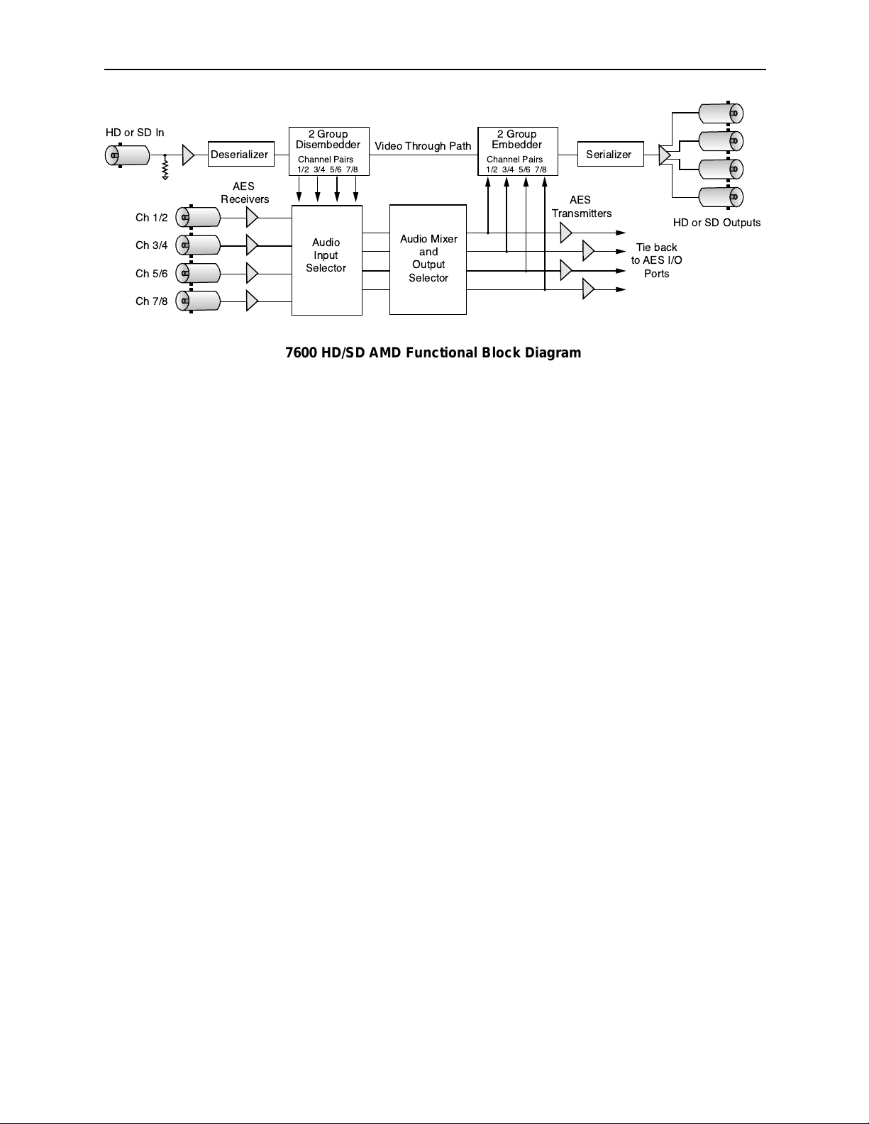
As shown in the block diagram on the following page, an HD or SD signal is fed to the
module for embedding of audio or audio extraction, depending on the mode chosen by the
user.
The module provides eight channels of digital audio processing. Digital audio inputs can
come from four AES ports and/or be disembedded from the HD or SD SDI input stream.
After processing, digital outputs in both AES and embedded form are possible.
There are four AES ports, consisting of the four AES BNC connectors on the rear of the
chassis. These BNCs become bi-directional ports. Each of them can either be an AES input
or an AES output. These four AES ports are associated with pairs of channels: Ch 1/2,
Ch 3/4, Ch 5/6, and Ch 7/8. A port will become an output if it has not been chosen as an
AES input in the Aud In A and B menus.
There are two disembedders on the input side referred to as A and B. These disembedders
are being fed the SDI video input stream in parallel and each of them can be independently targeted to any of the four possible groups. The A disembedder will produce two pairs of
audio signals, referred to as SDI 1/2 and SDI 3/4.
Model 7600 HD/SD AMD
7600-2
Page 3
Model 7600 HD/SD AMD
7600-3
The B disembedder will also produce two pairs of audio signals referred to as SDI 5/6 and
SDI 7/8. In the B disembedder, the SDI 5/6 pair corresponds to the first and second
channels in the selected group and SDI 7/8 is taken from the third and fourth channels in
that same group.
The disembedded audio can be processed with level adjustment and channel mixing, and
shuffling. It can then be embedded into the video output stream.
There are two embedders referred to as A and B to support the eight channels of audio,
one for each group. The embedders are placed in series with the A embedder first and the
B embedder second. Each embedder must be configured for operating mode and the
desired group (1 – 4) in which to embed the audio.
The configuration parameters for the embedders in the Audio Out menu are not identical.
There is no Replace All function for the B embedder as this function occurs in the
upstream embedder A.
Power for the module is derived from the ± 12 volt frame power. It is regulated to the
required +5 volts for the digital circuitry by on-board regulators. The required +3 volts for
the multiplexer circuitry is developed in a linear regulator running off the +5 volt supply.
The module is fused with a resettable fuse device. If the fuse opens due to an overcurrent
condition, the module will lose power. After pulling the module, the fuse will reset automatically requiring no replacement fuse.
The on-board CPU can monitor and report module ID information (slot location, software
version and board revision), and power status (+5 volts or +3 volts) to the optional frame
System Control module. This information can be accessed by the user or set to register an
alarm if desired using the remote control options available.
Module parameters can be adjusted through the control system with Avenue Touch
Screens, Express Control Panels, or the Avenue PC Application. Individual level controls
are available for all 8 channels. Memory registers can be used to save the complete configuration of the module, making it easy to change instantly between different configurations.
7600 HD/SD AMD Functional Block Diagram
HD or SD In
Ch 1/2
Ch 3/4
Ch 5/6
Ch 7/8
2 Group
Deserializer Serializer
AES
Receivers
Disembedder
Channel Pairs
1/2 3/4 5/6 7/8
Audio
Input
Selector
Video Through Path
Audio Mixer
and
Output
Selector
2 Group
Embedder
Channel Pairs
1/2 3/4 5/6 7/8
AES
Transmitters
HD or SD Outputs
Tie back
to AES I/O
Ports
Page 4
Model 7600 HD/SD AMD
7600-4
APPLICATIONS
There are four basic modes for using the 7600 module. Each of the modes is described
here.
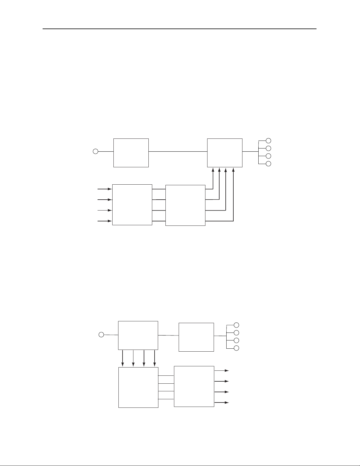
8 Channels AES Audio in, Embedded HD or SD Out
As shown in the block diagram below, the four AES audio input BNCs on the rear of the
frame can be used to input external audio which is then multiplexed into the HD or SD
output stream. To configure this mode, set the In 1/2, In 3/4, In 5/6, and In 7/8 controls in
the Aud In A and Aud In B menus to AES inputs. Inputs can be shuffled if desired using
the Aud Mix A and Aud Mix B menu. Inputs must be embedded into the output stream by
selecting the type of embedding and the audio group number in the Aud Out menu.
Embedded HD or SD Out, 8 Channels AES Audio Out
As shown in the block diagram below, the four AES audio input BNCs on the rear of the
frame can be used to output AES audio which has been disembedded from the HD or SD
input stream. To configure this mode, set the In 1/2, In 3/4, In 5/6, and In 7/8 controls in
the Aud In A and Aud In B menus to SDI inputs. Inputs can be shuffled if desired using
the Aud Mix A and Aud Mix B menus. Muxing must be set to Off in the Aud Out menu.
8 Channels AES Audio In, Embedded HD or SD Out
Embedded HD or SD Out, 8 Channels AES Audio Out
HD or SD
Video in
Rear
AES
BNCs
Ch 1/2
Ch 3/4
Ch 5/6
Ch 7/8
2 Group
Disembedder
Audio Input
Selector
Audio Mixer
and
Output
Selector
2 Group
Embedder
HD or SD
Video Out
HD or SD
Video in
2 Group
Disembedder
Audio Input
Selector
2 Group
Embedder
Audio Mixer
and
Output
Selector
Ch 1/2
Ch 3/4
Ch 5/6
Ch 7/8
HD or SD
Video Out
Rear
BNCs
AES
Page 5
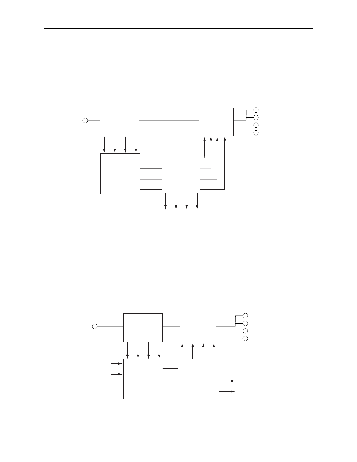
Embedded HD or SD In, Embedded HD or SD Out
In this mode, embedded audio from the HD or SD input stream is disembedded, shuffled
in the Audio Input Selector with the Aud Mix A and Aud Mix B menus if desired then reembedded into the output video stream as shown in the block diagram below. To configure
this mode, set the In 1/2, In 3/4, In 5/6, and In 7/8 controls in the Aud In A and Aud In B
menus to SDI inputs. Inputs can be shuffled if desired using the Aud Mix A and Aud Mix
B menus. Inputs must then be re-embedded by using the Mux controls in the Aud Output
menu.
4 Channels AES In, 4 Channels AES Out
In this mode, 2 external AES BNCs input 4 channels of AES audio into the Audio Input
Selector as shown below. The 4 channels can be shuffled in the Audio Input Selector with
the Aud Mix A and Aud Mix B menus if desired then sent to the other 2 external AES
BNCs as outputs. To configure this mode, set the In 1/2 and In 3/4 controls to AES inputs
and the In 5/6 and In 7/8 controls to SDI inputs in the Aud In A and Aud In B menus. In
the Aud Output menu, turn Muxing Off.
Model 7600 HD/SD AMD
7600-5
Embedded HD or SD In, Embedded HD or SD Out
4 Channel AES In, 4 Channels AES Out
HD or SD
Video in
2 Group
Disembedder
Audio Input
Selector
Ch 1/2
Ch 3/4
Ch 5/6
Ch 7/8
Audio Mixer
and
Output
Selector
Rear AES BNCs
Also Available
2 Group
Embedder
HD or SD
Video Out
HD or SD
Video in
Rear AES
BNCs
Ch 1/2
Ch 3/4
2 Group
Disembedder
Audio Input
Selector
2 Group
Embedder
(Embed Also)
Audio Mixer
and
Output
Selector
HD or SD
Video Out
Ch 5/6
Ch 7/8
Page 6

INSTALLATION
Plug the 7600 module into any slot in the 1 RU or 3 RU frame and install the plastic
overlay provided onto the corresponding group of rear BNC connectors associated with the
module location. Note that the plastic overlay has an optional adhesive backing for
securing it to the frame. Use of the adhesive backing is only necessary if you would like
the location to be permanent and is not recommended if you need to change module
locations.
This module may be hot-swapped (inserted or removed) without powering down or disturbing performance of the other modules in the system.
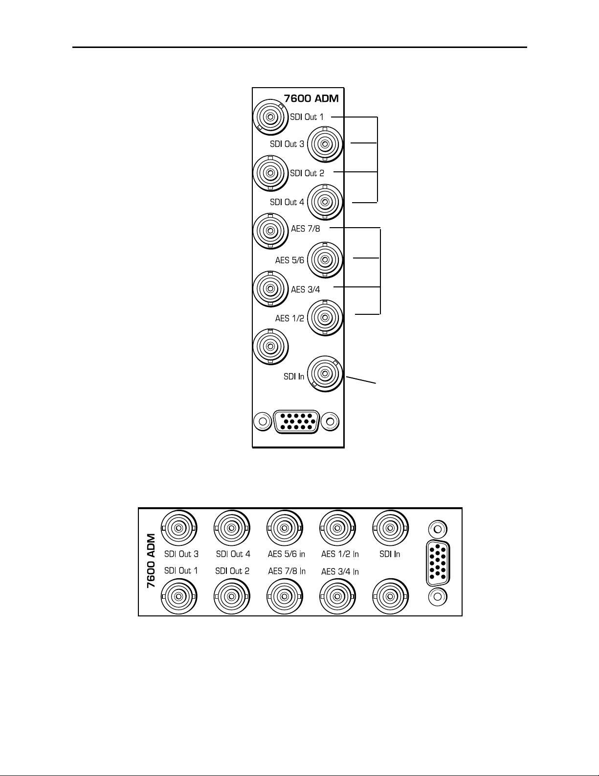
CABLING
Refer to the 3 RU and 1 RU backplane diagrams of the module on the following page for
cabling instructions. Note that unless stated otherwise, the 1 RU cabling explanations are
identical to those given in the 3 RU diagram.
Model 7600 HD/SD AMD
7600-6
Page 7
Model 7600 HD/SD AMD
7600-7
Connect an HD or SD video
signal to the SDI In BNC.
3 RU Backplane
1 RU Backplane
Connect the SDI Out 1-4
BNCs to the desired HD or
SD destinations.
Connect the AES A Out and
AES B Out BNCs to the
desired audio destinations,
if using as demux.
Page 8

MODULE CONFIGURATION AND CONTROL
The configuration parameters for each Avenue module must be selected after installation.
This can be done remotely using one of the Avenue remote control options or locally using
the module front panel controls. Each module has a REMOTE/LOCAL switch on the
front edge of the circuit board which must first be set to the control mode you will be
using.
The configuration parameter choices for the module will differ between Remote and
Local modes. In Remote mode, the choices are made through software and allow more
selections. The 7600 Parameter Table on the following page summarizes and compares
the various configuration parameters that can be set remotely or locally and the
default/factory settings. It also provides the default User Levels for each control. These
levels can be changed using the Avenue PC application.
If you are not using an remote control option, the module parameters must be configured
from the front panel switches. Parameters that have no front panel control will be set to a
default value. The Local switches are illustrated in the Front Panel Controls and
Indicators section following the 7600 Parameter Table.
Avenue module parameters can be configured and controlled remotely from one of the
remote control options, the Avenue Touch Screens, Express Control Panels, or the Avenue
PC Application. Once the module parameters have been set remotely, the information is
stored on the module CPU. This allows the module be moved to a different cell in the
frame at your discretion without losing the stored information. Remote configuration will
override whatever the switch settings are on the front edge of the module.
For setting the parameters remotely using the Avenue PC option, refer to the Avenue PC
Remote Configuration section of this document.
For setting the parameters remotely using the Avenue Touch Screen option, refer to the
Avenue Touch Screen Remote Configuration section of this data pack following
Avenue PC.
For setting the parameters remotely using the Avenue Express Control Panel option, refer
to the Avenue Express Control Panel data pack that comes with the panel option.
Model 7600 HD/SD AMD
7600-8
Page 9

Model 7600 HD/SD AMD
7600-9
7600 Parameter Table
CONTROL LOCAL REMOTE DEFAULT
DEFAULT
USER LEVEL
Strip Audio
Off
On
Off
Off Admin
Ch 1-8 In (level)
0 dB –70 to +12 dB 0 dB Level 1
Ch 1-8 Output Bus
Ch 1 – Output 1
Ch 2 – Output 2
Ch 3 – Output 3
Ch 4 – Output 4
Ch 5 – Output 5
Ch 6 – Output 6
Ch 7 – Output 7
Ch 8 – Output 8
Output Bus 1 – 8
Tie
Default
Invert
Ch 1 – Output 1
Ch 2 – Output 2
Ch 3 – Output 3
Ch 4 – Output 4
Ch 5 – Output 5
Ch 6 – Output 6
Ch 7 – Output 7
Ch 8 – Output 8
Level 1
Bulk Delay 0 msec 0 – 1000 msec 0 msec Level 1
1/2 Input
Switch 1:
AES (left)
SDI (right)
AES 1/2
AES 3/4
AES 5/6
AES 7/8
SDI 1/2
SDI 3/4
SDI 5/6
SDI 7/8
AES 1/2
Level 1
3/4 Input
AES 3/4
Level 1
5/6 Input
AES 5/6
Level 1
7/8 Input
AES 7/8
Level 1
1/2, 3/4, 5/6, 7/8
Mode
Auto
Audio
Data
Auto
Auto Level 1
Audio A and B
DeMux Group
Group 1
Group 1
Group 2
Group 3
Group 4
Group 1 Level 1
Mux Disable or
Position
Switch 2:
Mux On (left)
Mux Off (right)
Off
Replace
Cascade
Replace All
Replace All Level 1
Group Select
A and B
Switch 3 and 4:
GP0
GP1
Group 1
Group 2
Group 3
Group 4
Group 1 Level 1
Dig Ref Level
-20dBFS
-20 dBFS
-18 dBFS
-20 dBFS
Level 1
Memory Registers
N/A 1 – 5 Last Saved Level 1
Page 10

Remote/Local switch:
Set to the mode you will be using.
SDI In:
Video green LED:
ON indicates module is locked to a
valid input signal.
OFF indicates no valid video input
is present
.
Audio green LED:
ON indicates module detects
embedded audio.
OFF indicates no embedded audio
detected
.
Pwr green LED:
Indicates the presence (ON) or
(OFF) of power (+5V or -12V).
Run green LED:
OFF:
A power fault or halted CPU
ON:
A halted CPU
FAST BLINK:
CPU Run error
SLOW BLINK:
System OK. (If SPI control is
active from the main frame
System Control Module, all
Run indicators will be synchronized.).
AES Audio:
1/2, 3/4, 5/6, 7/8 In green LEDs:
ON when AES audio is detected
on channels.
OFF when no AES audio is
detected on channels.
AES/SDI In:
Set to AES (left) for external AES
audio or SDI (right) for demuliplexed
audio from the input SDI stream.
Mux On
:
Set multiplexing On (left) or Off (right)
Audio Group A:
Set to GP0 (left) or GP1 (right).
Audio Group B:
Set to GP0 (left) or GP1 (right).
Front Panel Controls and Indicators
Each front edge indicator and switch setting is shown in the diagram below:
Model 7600 HD/SD AMD
7600-10
Page 11

Avenue PC Remote Configuration
The Avenue PC remote control menus for this module are illustrated and explained below.
Refer to the 7600 Parameter Table shown earlier for a summary of available parameters
that can be set remotely through the menus illustrated. For more information on using
Avenue PC, refer to the Avenue PC Control Application Software data pack that came with
the option.
Parameter fields that are grayed out can indicate one of the following conditions:
• An option is not installed.
• The function is not active.
• The module is locked.
• The User Level set with Avenue PC is not accessible from the current User Level.
7600 Avenue PC Menus
The Vid In menu below provides the following read-only status reports on the input video:
• Input – reports the type of video input to the module as one of the following:
• No Input
• 720p/50
• 720p/59.94
• 1080i/50
• 1080i/59.94
• 1080p/25
• 1080p/23.98
• 1080sF/25
• 1080sf/23.98
• SD 525
• SD 625
• Unknown Std
• Input Error – reports any input errors to the module as one of the following:
• No Error
• No Lock
• EDH/CRC
• TRS Error
• Error Seconds – reports how long the input error has been occurring.
The Vid In menu below provides the controls for setting parameters on the video input:
• Strip Audio – check the Strip checkbox to strip audio off so it is not fed through
to the SDI output.
Model 7600 HD/SD AMD
7600-11
Page 12

Use the Aud Mix A menu below to control the audio mixing and shuffling of Input
Channels 1 through 4. Each output bus assignment will be indicated by a green box.
• Input Ch 1 – assign Input Channel 1 to the desired output bus or tie to Channel 2
and set the input level using the slider control or by entering a number
(-70 to +12 dB) in the window and pressing the Enter key.
• Input Ch 2 – assign Input Channel 2 to the desired output bus or tie to Channel 1
and set the input level using the slider control or by entering a number
(-70 to +12 dB) in the window and pressing the Enter key on your PC.
• Input Ch 3 – assign Input Channel 3 to the desired output bus or tie to Channel 4
and set the input level using the slider control or by entering a number
(-70 to +12 dB) in the window and pressing the Enter key on your PC.
• Input Ch 4 – assign Input Channel 4 to the desired output bus or tie to Channel 3
and set the input level using the slider control or by entering a number
(-70 to +12 dB) in the window and pressing the Enter key on your PC.
Selecting the Tie button in Input Ch 1 or Input Ch 2 will tie the two controls together.
Selecting the Tie button in Input Ch 3 or Input Ch 4 will tie the controls for these
channels together.
Select the Default button to return to the default value.
Select the Invert button to invert the phase of the audio input.
Model 7600 HD/SD AMD
7600-12
Page 13

For Channels 5 –8, use the Audio Mix B menu shown below to set the following
• Input Ch 5 – assign Input Channel 5 to the desired output bus or tie to
Channel 6. Set the input level using the slider control or by entering a number
(-70 to + 12 dB) in the window and pressing the Enter key on your PC.
• Input Ch 6 – assign Input Channel 6 to the desired output bus or tie to
Channel 5. Set the input level using the slider control or by entering a number
(-70 to + 12 dB) in the window and pressing the Enter key on your PC.
• Input Ch 7 – assign Input Channel 7 to the desired output bus or tie to
Channel 8. Set the input level using the slider control or by entering a number
(-70 to + 12 dB) in the window and pressing the Enter key on your PC.
• Input Ch 8 – assign Input Channel 8 to the desired output bus or tie to
Channel 7. Set the input level using the slider control or by entering a number
(-70 to + 12 dB) in the window and pressing the Enter key on your PC.
Selecting the Tie button in Input Ch 5 or Input Ch 6 will tie the two controls together.
Selecting the Tie button in Input Ch 7 or Input Ch 8 will tie the controls for these
channels together.
Select the Default button to return to the default value.
Select the Invert button to invert the phase of the audio input.
Model 7600 HD/SD AMD
7600-13
Page 14

Use the Aud Delay menu shown below to adjust the amount of audio delay on the output:
• Bulk Delay – set the amount of bulk delay using the left and right arrows or enter
a value in the msec field and press the Enter key on your PC.
The amount of total delay will be reported in nsec in the Total Delay window.
Model 7600 HD/SD AMD
7600-14
Page 15

Use the Aud In A menu shown on the next page adjust the following parameters:
• 1/2 Input – select the input audio source for Input 1/2.
• 3/4 Input – select the input audio source for Input 3/4.
When an AES input pair is selected as an input, the corresponding AES BNC on
the rear of the module will become an input. If an AES input is not selected, the
corresponding BNC on the rear of the module will automatically become an output.
Refer to the Applications section for an illustration of configuring the input/output
BNCs.
• 1/2 Mode – for a Serial input with embedded audio, select the type of audio in the
stream:
• Audio – the embedded stream is standard audio.
• Data – the embedded stream is a non-audio signal.
• Auto – the module will detect the type of signal embedded in the stream,
audio or data.
• 3/4 Mode – select the type of audio in the serial stream as described above.
• DeMux Group – select the embedded audio group to demultiplex from the selections. The status of embedded audio is shown in the Embed In view.
The status of the corresponding audio inputs are shown next to the control. Status is
reported as one of the following:
• No Input – no serial digital embedded audio is detected.
• Audio Sync – the audio embedded in the stream is synchronous with the timing
reference.
• Data Sync – the data embedded in the stream is synchronous with the timing
reference.
• Audio Async – the audio embedded in the stream is non-synchronous with the
timing reference.
Model 7600 HD/SD AMD
7600-15
Page 16

Use the Aud In B menu shown below to adjust the following parameters:
• 5/6 Input – select the input audio source for Input 5/6.
• 7/8 Input – select the input audio source for Input 7/8.
When an AES input pair is selected as an input, the corresponding AES BNC on
the rear of the module will become an input. If an AES input is not selected, the
corresponding BNC on the rear of the module will automatically become an output.
Refer to the block diagram on page 4 for an illustration of the input/output BNCs.
• 5/6 Mode – for a Serial input with embedded audio, select the type of audio in the
stream:
• Audio – the embedded stream is standard audio.
• Data – the embedded stream is a non-audio signal.
• Auto – the module will detect the type of signal embedded in the stream,
audio or data.
• 7/8 Mode – select the type of audio in the serial stream as described above.
• DeMux Group – select the embedded audio group to demultiplex from the selections. The status of embedded audio is shown in the Embed In view.
The status of the corresponding audio inputs are shown next to the control. Status is
reported as one of the following:
• No Input – no serial digital embedded audio is detected.
• Audio Sync – the audio embedded in the stream is synchronous with the timing
reference.
• Data Sync – the data embedded in the stream is synchronous with the timing
reference.
• Audio Async – the audio embedded in the stream is non-synchronous with the
timing reference.
Model 7600 HD/SD AMD
7600-16
Page 17

Use the Aud Out menu shown below to adjust the following audio output parameters:
• Audio Embed A – turn embedding Off for no embedding to take place in the
output signal. Select Replace to replace the targeted group in the stream with new
content. If there is no such group already present, the new content will be placed in
the horizontal interval in normal cascade, following any other content already
there. When Cascade is selected, the audio channels are placed after any existing
content. Replace All will strip all of the original content and the new content is
placed at the beginning of the horizontal interval.
• Audio Embed B – identical to Audio Embed A but no Replace All function is
required as this will occur upstream in the A embedder.
• Mux Group A – select the multiplexed group to be embedded in embedder A in the
output.
• Mux Group B – select the multiplexed group to be embedded in embedder B in the
output.
• Dig Ref Level – set the digital reference level for the audio output.
The Memory menu shown below allows you to save overall module setups to five memory
registers as follows:
• Select Save, then one of the five memory registers Reg 1 – 5. The box will turn
green. The entire module setup is now saved in the selected register.
• To recall a register, select the register box. If there is information saved, the box
will turn green. The saved setup will now be loaded to the module. Up to five
different module setups can be saved and recalled using the individual registers.
Model 7600 HD/SD AMD
7600-17
Page 18

AVENUE TOUCH SCREEN REMOTE CONFIGURATION
Avenue Touch Screen remote control menus for this module are illustrated and explained
below. Refer to the 7600 Parameter Table earlier in this section for a summary of
available parameters that can be set remotely through the menus illustrated. For more
information on using Avenue Touch Screen, refer to the Avenue System Overview that is
included in the Avenue manual.
Parameter fields that are grayed out can indicate one of the following conditions:
• An option is not installed.
• The function is not active.
• The module is locked.
• The User Level set with Avenue PC is not accessible from the current User Level.
Model 7600 HD/SD AMD
7600-18
Page 19

7600 Avenue Touch Screen Menus
The Vid In menu below provides the following read-only status reports for the input
video:
• Input – reports the type of video input to the module as one of the following:
• No Input
• 720p/50
• 720p/59.94
• 1080i/50
• 1080i/59.94
• 1080p/25
• 1080p/23.98
• 1080sF/25
• 1080sf/23.98
• SD 525
• SD 625
• Unknown Std
• Input Error – reports any input errors to the module as one of the following:
• No Error
• No Lock
• EDH/CRC
• TRS Error
• Error Seconds – reports how long the input error has been occurring.
The Vid In menu below provides the controls for setting parameters on the video input:
• Strip Audio – check the Strip checkbox to strip audio off so it is not fed through
to the SDI output.
Model 7600 HD/SD AMD
7600-19
Page 20

Use the Aud Mix A menu below to control the audio mixing and shuffling of Input
Channels 1 through 4. Each output bus assignment will be indicated by a green box.
• Input Ch 1 – assign Input Channel 1 to the desired output bus or tie to Channel 2
and set the input level using the slider control or by entering a number
(-70 to +12 dB) using the pop-up key pad and pressing Enter.
• Input Ch 2 – assign Input Channel 2 to the desired output bus or tie to Channel 1
and set the input level using the slider control or by entering a number
(-70 to +12 dB) using the pop-up key pad and pressing Enter.
• Input Ch 3 – assign Input Channel 3 to the desired output bus or tie to Channel 4
and set the input level using the slider control or by entering a number
(-70 to +12 dB) using the pop-up key pad and pressing Enter.
• Input Ch 4 – assign Input Channel 4 to the desired output bus or tie to Channel 3
and set the input level using the slider control or by entering a number
(-70 to +12 dB) using the pop-up key pad and pressing Enter.
Selecting the Tie button in Input Ch 1 or Input Ch 2 will tie the two controls together.
Selecting the Tie button in Input Ch 3 or Input Ch 4 will tie the controls for these
channels together.
Select the Default button to return to the default value.
Select the Invert button to invert the phase of the audio input.
Model 7600 HD/SD AMD
7600-20
Page 21

For Channels 5 –8, use the Audio Mix B menu shown below to set the following
• Input Ch 5 – assign Input Channel 5 to the desired output bus or tie to
Channel 6. Set the input level using the slider control or by entering a number
(-70 to + 12 dB) using the pop-up key pad and pressing Enter.
• Input Ch 6 – assign Input Channel 6 to the desired output bus or tie to
Channel 5. Set the input level using the slider control or by entering a number
(-70 to + 12 dB) using the pop-up key pad and pressing Enter.
• Input Ch 7 – assign Input Channel 7 to the desired output bus or tie to
Channel 8. Set the input level using the slider control or by entering a number
(-70 to + 12 dB) using the pop-up key pad and pressing Enter.
• Input Ch 8 – assign Input Channel 8 to the desired output bus or tie to
Channel 7. Set the input level using the slider control or by entering a number
(-70 to + 12 dB) using the pop-up key pad and pressing Enter.
Selecting the Tie button in Input Ch 5 or Input Ch 6 will tie the two controls together.
Selecting the Tie button in Input Ch 7 or Input Ch 8 will tie the controls for these
channels together.
Select the Default button to return to the default value.
Select the Invert button to invert the phase of the audio input.
Model 7600 HD/SD AMD
7600-21
Page 22

Use the Aud Delay menu shown below to adjust the amount of audio delay on the output:
• Bulk Delay – set the amount of bulk delay using the left and right arrows or enter
a value in the msec field and press the Enter key on your PC.
The amount of total delay will be reported in nsec in the Total Delay window.
Model 7600 HD/SD AMD
7600-22
Page 23

Use the Aud In A menu shown on the next page adjust the following parameters:
• 1/2 Input – select the input audio source for Input 1/2.
• 3/4 Input – select the input audio source for Input 3/4.
When an AES input pair is selected as an input, the corresponding AES BNC on
the rear of the module will become an input. If an AES input is not selected, the
corresponding BNC on the rear of the module will automatically become an output.
Refer to the block diagram on page 4 for an illustration of the input/output BNCs.
• 1/2 Mode – for a Serial input with embedded audio, select the type of audio in the
stream:
• Audio – the embedded stream is standard audio.
• Data – the embedded stream is a non-audio signal.
• Auto – the module will detect the type of signal embedded in the stream,
audio or data.
• 3/4 Mode – select the type of audio in the serial stream as described above.
• DeMux Group – select the embedded audio group to demultiplex from the selections. The status of embedded audio is shown in the Embed In view.
The status of the corresponding audio inputs are shown next to the control. Status is
reported as one of the following:
• No Input – no serial digital embedded audio is detected.
• Audio Sync – the audio embedded in the stream is synchronous with the timing
reference.
• Data Sync – the data embedded in the stream is synchronous with the timing
reference.
• Audio Async – the audio embedded in the stream is non-synchronous with the
timing reference.
Model 7600 HD/SD AMD
7600-23
Page 24

Use the Aud In B menu shown below to adjust the following parameters:
• 5/6 Input – select the input audio source for Input 5/6.
• 7/8 Input – select the input audio source for Input 7/8.
When an AES input pair is selected as an input, the corresponding AES BNC on
the rear of the module will become an input. If an AES input is not selected, the
corresponding BNC on the rear of the module will automatically become an output.
Refer to the block diagram on page 4 for an illustration of the input/output BNCs.
• 5/6 Mode – for a Serial input with embedded audio, select the type of audio in the
stream:
• Audio – the embedded stream is standard audio.
• Data – the embedded stream is a non-audio signal.
• Auto – the module will detect the type of signal embedded in the stream,
audio or data.
• 7/8 Mode – select the type of audio in the serial stream as described above.
• DeMux Group – select the embedded audio group to demultiplex from the selections. The status of embedded audio is shown in the Embed In view.
The status of the corresponding audio inputs are shown next to the control. Status is
reported as one of the following:
• No Input – no serial digital embedded audio is detected.
• Audio Sync – the audio embedded in the stream is synchronous with the timing
reference.
• Data Sync – the data embedded in the stream is synchronous with the timing
reference.
• Audio Async – the audio embedded in the stream is non-synchronous with the
timing reference.
7600-24
Model 7600 HD/SD AMD
Page 25

Use the Aud Out menu shown below to adjust the following audio output parameters:
• Audio Embed A – turn embedding Off for no embedding to take place in the
output signal. Select Replace to replace the targeted group in the stream with new
content. If there is no such group already present, the new content will be placed in
the horizontal interval in normal cascade, following any other content already
there. When Cascade is selected, the audio channels are placed after any existing
content. Replace All will strip all of the original content and the new content is
placed at the beginning of the horizontal interval.
• Audio Embed B – identical to Audio Embed A but no Replace All function is
required as this will occur upstream in the A embedder.
• Mux Group A – select the multiplexed group to be embedded in embedder A in the
output.
• Mux Group B – select the multiplexed group to be embedded in embedder B in
the output.
• Dig Ref Level – set the digital reference level for the audio output.
7600-25
Model 7600 HD/SD AMD
Page 26

The Memory menu allows you to save overall module setups to five memory registers as
follows:
• Select Save (it will light red), then select one of the five memory registers
Reg 1 – 5. The selected box will turn green. The entire module setup is now saved
in the selected register.
• To recall a register, select the register box. If there is information saved, the box
will turn green. The saved setup will now be loaded to the module. Up to five
different module setups can be saved and recalled using the individual registers.
7600-26
Model 7600 HD/SD AMD
Page 27

TROUBLESHOOTING
To aid in troubleshooting, the LED indicators can be easily monitored from the front
panel of this module to show module status.
If using the Remote mode, status items can also be monitored using the Avenue Touch
Screen Control Panel or PC Application:
Refer to the overall troubleshooting tips given below for the module:
No status lights are lit on front panel:
• Check that frame power is present (green LED{s} on frame power supplies).
• Check that module is firmly seated in frame. Try removing it and plugging
it in again.
Can’t control module:
• Check status of CPU Run green LED. Should be blinking slowly and in
unison with other modules if System module is present. If not, try removing
it and plugging it in again.
• System module may not be working properly if installed.
Module controls are grayed out:
• Module is locked or access to module controls is restricted by User Level.
• Local/Remote switch on module is in the Local position.
No signal out of module:
• Check status of Video and AES 1/2, 3/4. 5/6, 7/8 green LEDs. Should be lit.
If not, check the input signal for presence and quality.
• Check correct mode (Mux or Demux) assignment has been made using
Audio In menus.
• Check cabling to input of module.
You may also refer to the technical support section of the Ensemble web site for the latest
information on your equipment at the URL below:
http://www
.ensembledesigns.com/support
SOFTWARE UPDATING
Software upgrades for each module can be downloaded remotely if the optional System
Control module is installed. These can be downloaded onto your PC and then Avenue PC
will distribute the update to the individual module. (Refer to the Avenue PC documentation for more information) Periodically updates will be posted on our web site. If you do
not have the required System Control Module and Avenue PC, modules can be sent back
to the factory for software upgrades.
Model 7600 HD/SD AMD
7600-27
Page 28

7600-28
Model 7600 HD/SD AMD
WARRANTYAND FACTORY SERVICE
Warranty
This Module is covered by a five year limited warranty, as stated in the main Preface of
this manual. If you require service (under warranty or not), please contact Ensemble
Designs and ask for customer service before you return the unit. This will allow the
service technician to provide any other suggestions for identifying the problem and
recommend possible solutions.
Factory Service
If you return equipment for repair, please get a Return Material Authorization Number
(RMA) from the factory first.
Ship the product and a written description of the problem to:
Ensemble Designs, Inc.
Attention: Customer Service RMA #####
870 Gold Flat Rd.
Nevada City, CA. 95959 USA
(530) 478-1830
Fax: (530) 478-1832
service@ensembledesigns.com
http://www.ensembledesigns.com
Be sure to put your RMA number on the outside of the box.
Page 29

SPECIFICATIONS
7600 HD/SD AMD
SD Video Input Signal
Number One
Signal Type: Serial Digital (SMPTE 259M)
Impedance: 75 Ω BNC
Return Loss: >15 dB
Maximum
Cable Length: 300 meters
HD Video Input Signal
Number One
Signal Type: HD Serial Digital 1.485 Gb/s (SMPTE 274M or 296M)
Impedance: 75 Ω BNC
Return Loss: >15 dB
Maximum
Cable Length: 100 meters (Belden 1694A or equivalent)
HD Standards Supported:
1080i (SMPTE 274M-4, 5, 6) 50, 59.94 or 60 Hz
720p (SMPTE 296M-1,2,3) 59.94 or 60 Hz
1080p (SMPTE 274M-9, 10, 11) 23.98 24, 25 Hz
1080sF (RP 211 -14, 15, 16) 23.98, 24, 25 Hz
Serial Digital Output
Number: Four
Signal Type: Same as input, Serial Digital (SMPTE 259M) or
HD Serial Digital 1.485 Gb/s (SMPTE 274M or 296M)
Impedance: 75 Ω BNC
Return Loss: >15 dB
Output DC: None (ac coupled)
AES/EBU Digital Inputs
Number Four (total of eight channels)
Type: AES3id
Connectorization Coaxial, 75 Ω BNC
Bit Depth 20 or 24 bit
Sample Rate 30 kHz to 100 kHz (sample rate converted internally to 48 kHz)
Crosstalk <144 dB
Dynamic Range >144 dB
Reference Level -18 or -20 dBFS (selectable)
AC-3, Dolby-E Supported when inputs are synchronous
Model 7600 HD/SD AMD
7600-29
Page 30

Embedded Inputs
Number Four AES Streams (from video input)
Eight channels from any two of four groups
Channels: Eight
Bit Depth: 20 or 24 bit
AES/EBU Digital Outputs
Number Four (total of 8 channels)
Type: AES3id
Connectorization Coaxial, 75 Ω BNC
Bit Depth 20 or 24 bit
Sample Rate 48 kHz
Synchronous to video input
Crosstalk >144 dB
Dynamic Range >144 dB
Reference Level -18 or -20 dBFS (selectable)
Embedded Outputs
Group Assign: Cascade or Replace any two of four groups
Channels: Eight
Bit Depth: 24 bit
General Specifications
Power Consumption: 10.0 watts
Temperature Range: 0 to 40 degrees C ambient (all specs met)
Relative Humidity: 0 to 95% noncondensing
Altitude: 0 to 10,000 ft
Due to ongoing product development, all specifications subject to change.
Model 7600 HD/SD AMD
7600-30
 Loading...