

Page 1
Model 7555 HD/SD,
Model 9550 3G/HD/SD,
Model 9550-XA 3G/HD/SD
Video Processing Frame Synchronizer
User Guide
Revision 1.1 SW v2.2.10
Page 2
Clearly, Ensemble wants to be in the broadcast equipment business. It’s so rare anymore to nd a company of this
caliber that has not been gobbled up by a large corporation. They are privately held so they don’t have to please the
money people. They really put their eorts into building products and working with customers.
I’m really happy with the Avenue products and Ensemble’s service, and even more important my engineers are happy.
We’ve continued to upgrade the product and add more cards. We will be rebuilding our production control room and
we will use Avenue again.
~ Don McKay, Vice President Engineering, Oregon Public Broadcasting
Who is Ensemble Designs?
By Engineers, For Engineers
In 1989, a former television station engineer who loved
designing and building video equipment, decided to
start a new company. He relished the idea of taking
an existing group of equipment and adding a few
special pieces in order to create an even more elegant
Avenue frames handle 270 Mb/s,
1.5 Gb/s and 3 Gb/s signals,
audio and MPEG signals. Used
worldwide in broadcast, mobile,
production, and post.
ensemble. So, he designed and built his first product and
the company was born.
Focused On What You Need
As the company has grown, more former TV station
engineers have joined Ensemble Designs and this wealth
of practical experience fuels the company’s innovation.
Everyone at the company is focused on providing the
We’re focused on
processing gear–
3G/HD/SD/ASI video,
audio and optical modules.
very equipment you need to complete your ensemble
of video and audio gear. We offer those special pieces
that tie everything together so that when combined, the
whole ensemble is exactly what you need.
Notably Great Service for You
We listen to you – just tell us what you need and we’ll
do our best to build it. We are completely focused on
you and the equipment you need. Being privately held
means we don’t have to worry about a big board of
directors or anything else that might take attention away
from real business. And, you can be sure that when you
call a real person will answer the phone. We love this
business and we’re here to stay.
Bricks and Mortar of Your Facility
The bricks and mortar of a facility include pieces like
up/downconverters, audio embedders, video converters,
routers, protection switches and SPGs for SD, HD and
3Gb/s. That’s what we’re focused on, that’s all we do
– we make proven and reliable signal processing and
infrastructure gear for broadcasters worldwide, for you.
Come on by and visit us.
Drop in for lunch and a tour!
Shipped with care to
television broadcasters
and video facilities all
over the world.
Page 3

7555 HD/SD, 9550 3G/HD/SD, and 9550-XA 3G/HD/SD Video Processing Frame Synchronizers
Contents
Video Processing Frame Sync Modules Overview 7
Shared Functionality 7
Shared Options 7
Key Differences 7
Flexible Synchronization 7
Uncompressed Bandwidth 7
Complete Proc Amp Functions 8
Audio Support 8
Dolby Decoding and Encoding 8
LevelTrack Audio Loudness Control AGC and Compliance Options 8
Configurable Mux or Demux 8
In-Line Processing 9
Software Requirements 9
Avenue System Control Modules 9
Download Link for Avenue System Control Software Version 2.2.12 9
Avenue PC Control Application 9
Download Link for Avenue PC Software Version 2.0.15 9
Installation and Cabling 10
Configuring the Analog Audio and Balanced Digital Data Jumper Connectors 10
The 15-Pin D Connector and Digital Data (Dolby Metadata) 10
Frame Slot Placement 11
Cabling for the Avenue 7555 12
Cabling for the Avenue 9550 13
Cabling for the Avenue 9550-XA 14
Functional Block Diagrams 15
For the Avenue 7555 15
For the Avenue 9550 16
For the Avenue 9550-XA 17
Applications 18
Timing of an Asynchronous Input 18
Embedding AES Audio and Adjusting Video with Internal Proc Amp 18
www.ensembledesigns.com Avenue 7555, 9550, 9550-XA - Page 3
Page 4

7555 HD/SD, 9550 3G/HD/SD, and 9550-XA 3G/HD/SD Video Processing Frame Synchronizers
Three Use Cases for the 9615 AES, Analog Audio, and Data I/O Software Key Option 19
Embedding 19
Disembedding 20
In-Line Processing 20
Module Configuration and Control 21
Avenue PC Option 21
Avenue Touch Screen Option 21
Front Panel Controls and Indicators 21
For the Avenue 7555 21
For the Avenue 9550 22
For the Avenue 9550-XA 23
Avenue PC Remote Configuration 24
Avenue PC and Avenue Touch Screen Menus 24
Input Menu 24
Signal Types Accepted by 7555 24
Signal Types Accepted by 9550 and 9550-XA 24
Incoming Video Signal Reporting 24
Reference Menu 27
Setting the Reference Input Source 27
Timing Menu 28
Conguring the Frame Synchronizer 28
Proc Menu 30
Adjusting Video Processing Parameters 30
Aud Stat Menu 32
Reporting Audio Input Sync Status 32
Aud Cfg Menu 33
Conguring Analog Audio Outputs and LevelTrack Audio Loudness Control
AGC Software Option 33
Meter Mode 33
Meter Position 33
LKFS Average Time 34
Mux Out Menu 35
Selecting the Audio Channels to Embed into the Outgoing SDI Signal 35
Placing the Encoder Output 35
www.ensembledesigns.com Avenue 7555, 9550, 9550-XA - Page 4
Page 5

7555 HD/SD, 9550 3G/HD/SD, and 9550-XA 3G/HD/SD Video Processing Frame Synchronizers
Aud AGC Menu 37
LevelTrack Conguration 37
AGC Master 37
Final Gain 37
Silence Limit 37
Target Level 37
Spread 38
Transition Time 38
Max Atten 38
Max Gain 38
Chart 40
Mix 1:4, Mix 5:8, Mix 9:12, Mix 13:16 Menus 41
Combinations of Input Channels 41
Out Bus Assignments 42
Automatic Gain Control (AGC) (Optional) 43
Conguring Audio Output (9615 Software Key Option Required) 43
Conguring Digital Audio Outputs (9615 Software Key Option Required) 43
In 1:4, In 5:8, In 9:12, In 13:16 Menus 44
Selecting Audio Input Type and Routing to Mixer Input Channels 44
Using the In 1:4, In 5:8, In 9:12, In 13:16 Menus for Embedding 45
Using the In 1:4, In 5:8, In 9:12, In 13:16 Menus for Disembedding 46
Using the In 1:4, In 5:8, In 9:12, In 13:16 Menus for Disembedding (Cont’d) 47
Using the In 1:4, In 5:8, In 9:12, In 13:16 Menus for In-line Processing 48
Using the In 1:4, In 5:8, In 9:12, In 13:16 Menus for In-line Processing (Cont’d) 49
Audio Mode, Data Mode, Auto Mode 50
Decoder Menu 51
Decoding Dolby E, Dolby D/AC-3 (7615 Software Key Option Required) 51
Encoder Menu 53
Encoding Dolby E, Dolby D/AC-3 (7630, 7635 Software Key Option Required) 53
BNC Status Menu 55
Verifying BNC Directional Status 55
License Menu 56
Entering the Key and Activating AGC 56
Memory Menu 57
Saving and Recalling Conguration Settings 57
www.ensembledesigns.com Avenue 7555, 9550, 9550-XA - Page 5
Page 6

7555 HD/SD, 9550 3G/HD/SD, and 9550-XA 3G/HD/SD Video Processing Frame Synchronizers
Software Updating 58
Warranty and Factory Service 58
Specifications 59
Glossary 61
www.ensembledesigns.com Avenue 7555, 9550, 9550-XA - Page 6
Page 7

7555 HD/SD, 9550 3G/HD/SD, and 9550-XA 3G/HD/SD Video Processing Frame Synchronizers
Video Processing Frame Sync Modules Overview
The 7555 HD/SD, 9550 3G/HD/SD, and 9550-XA 3G/HD/SD video processing frame sync modules are
used for processing, synchronizing and timing 3 Gb/s or 1.5 Gb/s high definition video or standard
definition video signals. They share the same essential functions, with a couple of key differences.
These differences have to do with the type of video signal accepted (HD versus 3G), the number
of BNC ports available for digital audio, and the number of BNC ports available for SDI video signal
output.
Shared Functionality
All three modules can do video processing. All three have frame synchronizing functionality. Both the
7555 and 9550 have one SDI input, one reference input, four SDI outputs, and four AES I/O ports.
Shared Options
All three modules share the following set of options that extend their capabilities with software keys:
• 7615 Dolby™ E, Dolby D/AC-3 Decoder sub module and software key option
• 7630 Dolby E Encoder sub module and software key option
• 7635 Dolby D/AC-3 Encoder sub module and software key option
• 9615 AES, analog audio, and data I/O software key option
• 9670 LevelTrack™ Audio Loudness Control AGC software key option
• 9690 Audio Compliance and Monitoring software key option
Key Differences
The 7555 accepts a 1.5 Gb/s high definition or standard definition video signal. The 9550 has the
additional capability of accepting a 3 Gb/s high definition video signal.
The 9550-XA option adds two AES I/O ports (for a total of six rather than four), and removes two SDI
outputs (for a total of two rather than four).
Flexible Synchronization
An adjustable timing system genlocks to house reference. The modules genlock to either composite
video (PAL or NTSC) or to HD Tri-Level Sync. The modules can lock to the frame’s master reference or
reference can be connected directly to the modules’ external reference BNC. The serial output timing
can be set anywhere within a frame of the selected input reference.
Upon loss of signal, the modules provide freeze frame or black until the signal is recovered. In freeze
mode, audio can be muted or passed.
Uncompressed Bandwidth
The 3G, HD or SD SDI input is carried at full, uncompressed bandwidth throughout the entire module.
www.ensembledesigns.com Avenue 7555, 9550, 9550-XA - Page 7
Page 8

7555 HD/SD, 9550 3G/HD/SD, and 9550-XA 3G/HD/SD Video Processing Frame Synchronizers
Complete Proc Amp Functions
The modules have a full-featured Proc Amp capability for adjustment of every signal parameter. Proc
controls include Gain, Chroma, Pedestal and Hue.
Audio Support
All three modules include a full-featured, sixteen-channel audio mixer. The channel swap and shuffle
capability allows you to completely rearrange and remix audio channels. It provides precise control
over audio level, with up to 12 dB of gain to compensate for low level sources. Delay is adjustable up
to one second. The audio mixer can be used for embedded audio and for audio sourced from the AES
or analog inputs.
The 9615 AES and analog audio I/O software key option is required if you want to use the AES or
analog inputs and outputs. For the 7555 and 9550 modules, the 9615 option provides four AES input/
output ports for eight channels of I/O and also provides four channels of analog audio I/O. For the
9550-XA module, the 9615 option provides six AES input/output ports for twelve channels of I/O,
along with four channels of analog audio I/O.
Dolby Decoding and Encoding
Any of the three modules can be fitted with Dolby encoding and decoding options. The 7615 Dolby
decoding option can be fed from either an AES input or an AES stream disembedded from the
incoming SDI signal. The resulting discrete surround signals are then selectable as inputs to the sixteen
channel mixer/shuffler.
The 7630 Dolby E encoder and 7635 Dolby D/AC-3 encoder are fed from selected outputs of the
sixteen channel mixer/shuffler. The resulting encoded bitstream can be output both on an AES output
and embedded into the SDI outputs.
Additionally, the 7555, 9550 and 9550-XA fully support embedding and disembedding of encoded
multi-channel bitstreams such as Dolby E and Dolby D/AC-3.
LevelTrack Audio Loudness Control AGC and Compliance Options
The 9670 LevelTrack Audio Loudness Control AGC software key can be added as an option. LevelTrack
provides control for keeping audio levels consistent in program material. The 9690 Audio Compliance
and Monitoring Software can be added for compliance verification and archiving.
Configurable Mux or Demux
When configured as a multiplexer, the 7555 and 9550 have one serial digital video input and four AES
audio inputs. These four AES streams are embedded into the video stream. AES inputs are sample rate
converted, allowing the use of asynchronous audio. The output of the module is a digital stream that
contains the original video signal and four AES pairs, or eight channels.
The 9550-XA has one serial digital video input and six AES audio inputs, supporting six AES pairs, or
twelve channels.
When configured as a demultiplexer, audio signals present in the incoming video signal are extracted
and delivered as standard AES digital audio streams.
www.ensembledesigns.com Avenue 7555, 9550, 9550-XA - Page 8
Page 9

7555 HD/SD, 9550 3G/HD/SD, and 9550-XA 3G/HD/SD Video Processing Frame Synchronizers
All three modules include a sixteen-channel audio mixer. The channel swap and shuffle capability
allows you to completely rearrange and remix audio channels. It provides precise control over audio
level, with up to 12 dB of gain to compensate for low level sources. Delay is adjustable up to one
second.
In-Line Processing
Because the 7555, 9550 and 9550-XA have simultaneous disembedding and embedding, they are
in-line processors for embedded audio. They can take embedded content, adjust levels and remap
channels, and deliver it to the output as an embedded signal.
Software Requirements
The Avenue System Control Modules and the Avenue PC Control Software require the latest software
versions in order to work properly with the 7555, 9550 and 9550-XA modules.
Avenue System Control Modules
The Avenue System Control Modules provide the Serial, Ethernet and AveNet interface connections to
an Avenue frame, whether you are using the 5030 3RU System Control Module, the 5035 1RU System
Control Module, or the Tabletop Touch Screen Control Panel.
Download Link for Avenue System Control Software Version 2.2.12
Download and install Avenue System Control software version 2.2.12 from the Ensemble Designs web
site at the following link:
http://www.ensembledesigns.com/support/avenue-support/avenue-software
Avenue PC Control Application
Every function and parameter on the 7555, 9550 and 9550-XA can be controlled from the Avenue PC
Control Application.
Download Link for Avenue PC Software Version 2.0.15
Download and install Avenue PC software version 2.0.15 from the Ensemble Designs web site at the
following link:
http://www.ensembledesigns.com/support/avenue-support/avenue-pc-software
www.ensembledesigns.com Avenue 7555, 9550, 9550-XA - Page 9
Page 10
7555 HD/SD, 9550 3G/HD/SD, and 9550-XA 3G/HD/SD Video Processing Frame Synchronizers
Installation and Cabling
Configuring the Analog Audio and Balanced Digital Data Jumper
Connectors
Note: This functionality requires the 9615 AES, analog audio, and data I/O software key
option.
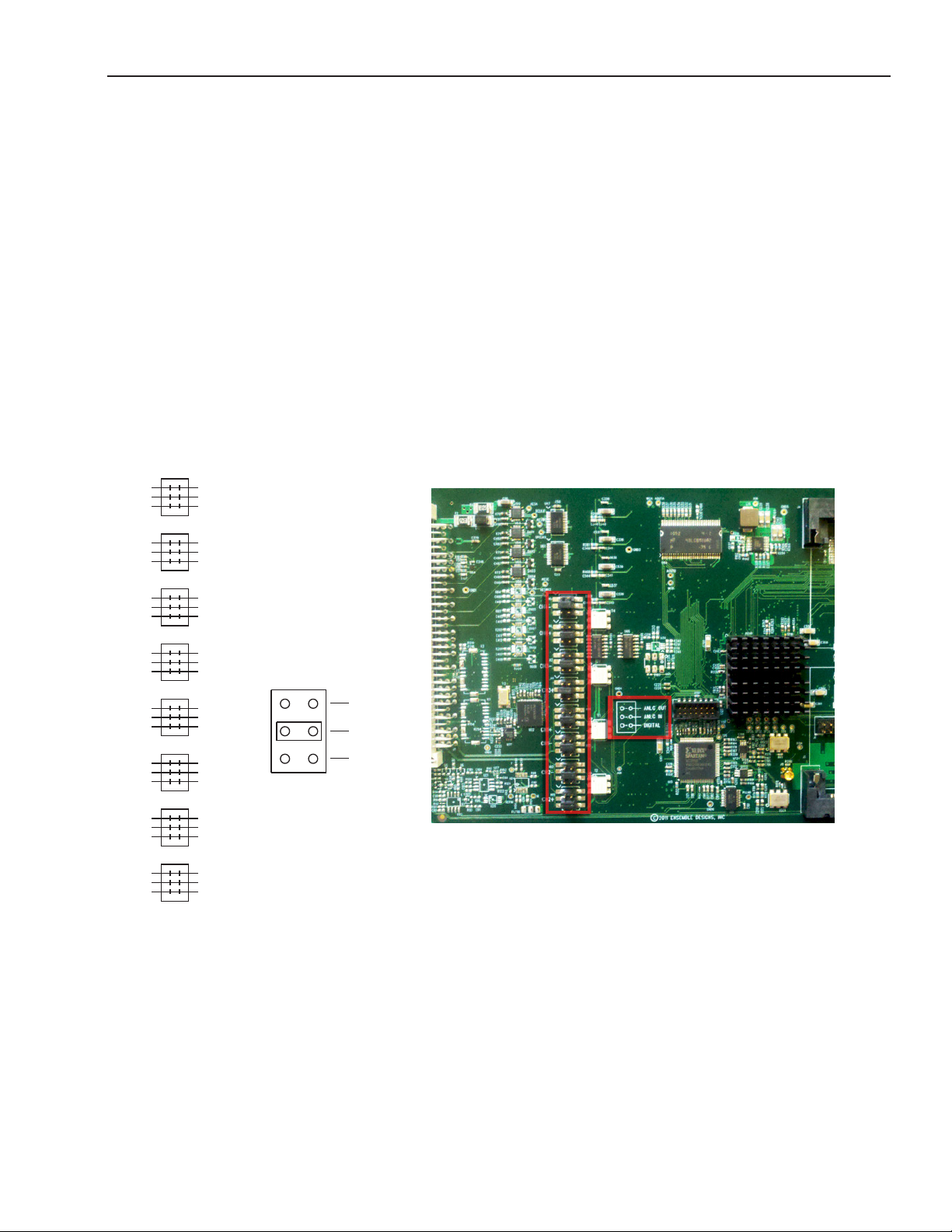
Before you can use the 15-pin D connector for analog audio out, analog audio in or digital, you must
first install analog audio and balanced digital data jumper connectors onto the module’s board.
There are eight connectors (four pairs) that map to the 15-pin D connector. Each connector has three
possible configurations—analog out, analog in, and digital data.
The 15-Pin D Connector and Digital Data (Dolby Metadata)
Unlike some other Avenue modules, the only purpose for the digital data capability of the 15-pin D
connector is for Dolby metadata; it cannot be used for serial control.
CH4-
CH4+
CH3-
CH3+
CH1+
CH1-
CH2-
ANLG OUT
ANLG IN
DIGITAL
DATA
Note the portion of the board pictured above (outlined in
red) that resembles the illustration to the left.
CH2+
The illustration to the left of the above photo reflects the placement of the connectors on the 7555,
9550 and 9550-XA boards (shown in the photograph on the right) for channels 1 through 4. The
positive and negative connectors for each channel are indicated on the board.
For each of the eight connectors, use the jumper to connect the top pair for analog audio out, the
middle pair for analog audio in, and the lower pair for digital data.
www.ensembledesigns.com Avenue 7555, 9550, 9550-XA - Page 10
Page 11

7555 HD/SD, 9550 3G/HD/SD, and 9550-XA 3G/HD/SD Video Processing Frame Synchronizers
Frame Slot Placement
Plug the 7555, 9550 or 9550-XA module into any one of the slots (except slot 1) in the 3RU frame or
any slot (except slot 3) in the 1RU frame. Install the plastic overlay provided onto the corresponding
group of rear BNC connectors associated with the module location. Note that the plastic overlay
has an optional adhesive backing for securing it to the frame. Use of the adhesive backing is only
necessary if you would like the location to be permanent and is not recommended if you need to
change module locations. This module may be hot-swapped (inserted or removed) without powering
down or disturbing performance of the other modules in the system.
Note: We recommend installing the 7555, 9550 or 9550-XA in slots 2 through 10 rather
than slot 1 for the 3RU frame.
www.ensembledesigns.com Avenue 7555, 9550, 9550-XA - Page 11
Page 12
7555 HD/SD, 9550 3G/HD/SD, and 9550-XA 3G/HD/SD Video Processing Frame Synchronizers
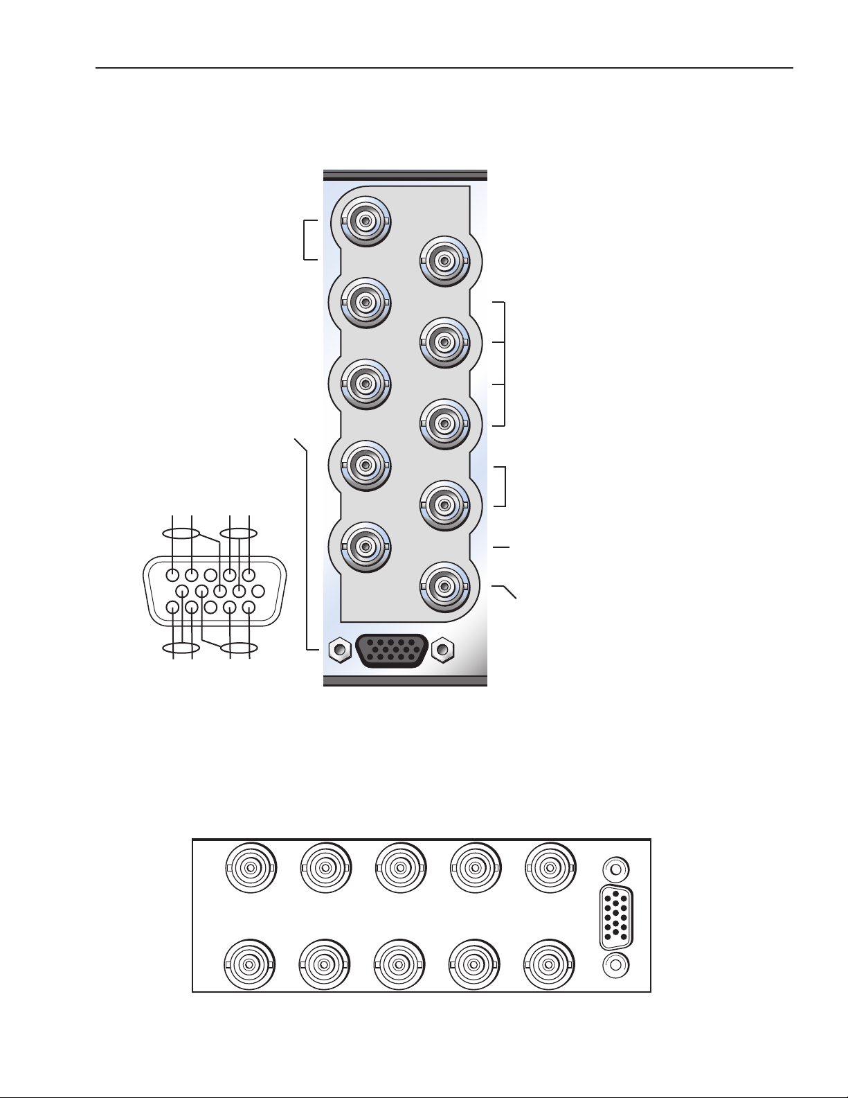
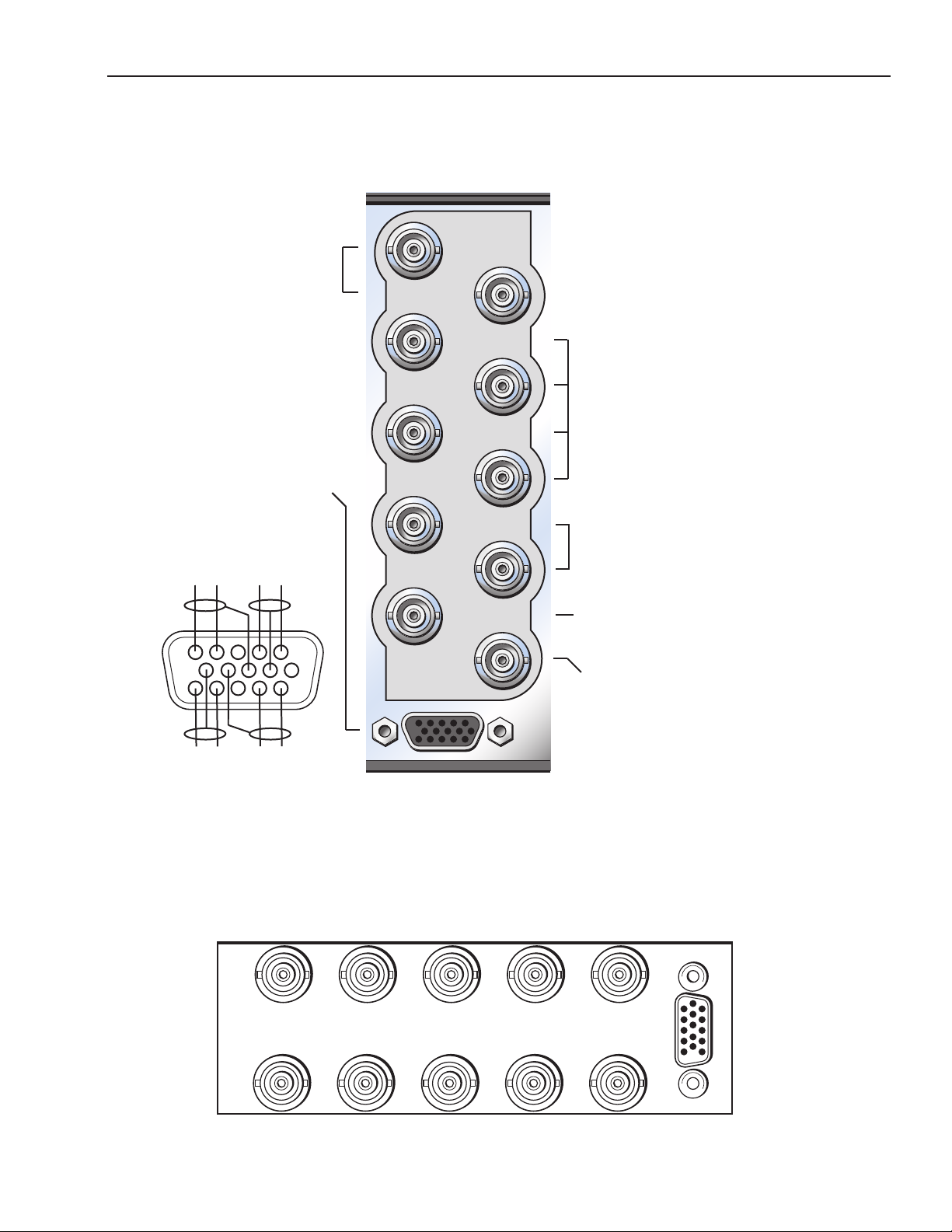
Cabling for the Avenue 7555
Refer to the 3RU and 1RU backplane diagrams of the module below for cabling instructions. Note that
unless stated otherwise, the 1RU cabling explanations are identical to those given in the 3RU diagram.
Four independent AES ports
SDI Out 3 and 4: Serial
digital video output
supporting 1.5 Gb/s HD
or 270 Mb/s SD video
signals.
15-pin D connector
supports up to four
channels of analog
audio selectable as
inputs or outputs. For
decoding and encoding,
it also supports Dolby
metadata. The D
connector does not
support serial control.
-
AUD 1
-
+
AUD 2
+
7555 VAP
SDI Out 4
SDI Out 3
AES 1/2
AES 3/4
AES 5/6
AES 7/8
SDI Out 2
SDI Out 1
Fail-safe
(supporting four AES pairs or
eight channels), each
configurable as input or
output. Embedding and
disembedding may be
performed simultaneously.
AES ports also serve as inputs
or outputs for decoding or
encoding Dolby E and AC-3
multichannel bitstreams, and
for non-audio PCM data
packaged into AES audio
format per SMPTE 337M.
SDI Out 1 and 2: Serial
digital video output
supporting 1.5 Gb/s HD
or 270 Mb/s SD video
signals.
Ref In
1
6
11
HD/SD In
Serial/Analog Audio
Ref In: Accepts PAL or NTSC
composite video or
HD Tri-Level Sync.
SDI In: Serial digital video
input. Supports 1.5 Gb/s HD
or 270 Mb/s SD video signals.
+
AUD 4
-
+
AUD 3
-
AUD 1 is on pins 1 and 2 and the associated ground is pin 7. Pin 1 is positive. AUD 2 is on pins 4 and
5 and the associated ground is pin 8. Pin 5 is positive. AUD 3 is on pins 11 and 12 and the associated
ground is pin 9. Pin 11 is positive. AUD 4 is on pins 14 and 15 and the associated ground is pin 10. Pin
15 is positive.
Dolby metadata can be connected in place of audio on any of the audio pairs.
SDI Out 3
SDI Out 4
7555 VAP
AES 3/4
AES 1/2 AES 5/6
AES 7/8
SDI Out 1
Fail-safe
SDI Out 2
HD/SD In
Ref In
Serial/Analog Audio
www.ensembledesigns.com Avenue 7555, 9550, 9550-XA - Page 12
Page 13
7555 HD/SD, 9550 3G/HD/SD, and 9550-XA 3G/HD/SD Video Processing Frame Synchronizers
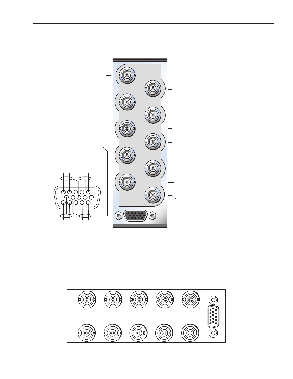
Cabling for the Avenue 9550
Refer to the 3RU and 1RU backplane diagrams of the module below for cabling instructions. Note that
unless stated otherwise, the 1RU cabling explanations are identical to those given in the 3RU diagram.
Four independent AES ports
SDI Out 3 and 4: Serial
digital video output
supporting 3 Gb/s,
1.5 Gb/s HD or 270 Mb/s
SD video signals.
15-pin D connector
supports up to four
channels of analog
audio selectable as
inputs or outputs. For
decoding and encoding,
it also supports Dolby
metadata. The D
connector does not
support serial control.
-
AUD 1
-
+
AUD 2
+
9550 VAP
SDI Out 4
SDI Out 3
AES 1/2
AES 3/4
AES 5/6
AES 7/8
SDI Out 2
SDI Out 1
Fail-safe
(supporting four AES pairs or
eight channels), each
configurable as input or
output. Embedding and
disembedding may be
performed simultaneously.
AES ports also serve as inputs
or outputs for decoding or
encoding Dolby E and AC-3
multichannel bitstreams, and
for non-audio PCM data
packaged into AES audio
format per SMPTE 337M.
SDI Out 1 and 2: Serial
digital video output
supporting 3 Gb/s,
1.5 Gb/s HD or 270 Mb/s
SD video signals.
Ref In
1
6
11
3G/HD/SD In
Serial/Analog Audio
Ref In: Accepts PAL or NTSC
composite video or
HD Tri-Level Sync.
SDI In: Serial digital video
input. Supports 3 Gb/s,
1.5 Gb/s HD or 270 Mb/s SD
+
AUD 4
-
-
AUD 3
+
video signals.
AUD 1 is on pins 1 and 2 and the associated ground is pin 7. Pin 1 is positive. AUD 2 is on pins 4 and
5 and the associated ground is pin 8. Pin 5 is positive. AUD 3 is on pins 11 and 12 and the associated
ground is pin 9. Pin 11 is positive. AUD 4 is on pins 14 and 15 and the associated ground is pin 10. Pin
15 is positive.
Dolby metadata can be connected in place of audio on any of the audio pairs.
SDI Out 3
SDI Out 4
9550 VAP
AES 3/4
AES 1/2 AES 5/6
AES 7/8
SDI Out 1
Fail-safe
SDI Out 2
3G/HD/SD In
Ref In
Serial/Analog Audio
www.ensembledesigns.com Avenue 7555, 9550, 9550-XA - Page 13
Page 14
7555 HD/SD, 9550 3G/HD/SD, and 9550-XA 3G/HD/SD Video Processing Frame Synchronizers
Cabling for the Avenue 9550-XA
Refer to the 3RU and 1RU backplane diagrams of the module below for cabling instructions. Note that
unless stated otherwise, the 1RU cabling explanations are identical to those given in the 3RU diagram.
SDI Out 2: Serial digital
video output supporting
3 Gb/s, 1.5 Gb/s HD or 270
Mb/s SD video signals.
15-pin D connector
supports up to four
channels of analog
audio selectable as
inputs or outputs. For
decoding and encoding,
it also supports Dolby
metadata. The D
connector does not
support serial control.
-
-
AUD 1
-
-
AUD 3
+
1
6
11
+
AUD 2
+
+
AUD 4
9550-XA VAP
SDI Out 2
AES 1/2
AES 3/4
AES 5/6
AES 7/8
AES 9/10
AES 11/12
SDI Out 1
Fail-safe
Ref In
3G/HD/SD In
Audio
Six independent AES ports
(supporting six AES pairs or
twelve channels), each
configurable as input or
output. Embedding and
disembedding may be
performed simultaneously.
AES ports also serve as inputs
or outputs for decoding or
encoding Dolby E and AC-3
multichannel bitstreams, and
for non-audio PCM data
packaged into AES audio
format per SMPTE 337M.
SDI Out 1: Serial digital video
output supporting 3 Gb/s, 1.5 Gb/s
HD or 270 Mb/s SD video signals.
Ref In: Accepts PAL or NTSC
composite video or
HD Tri-Level Sync.
SDI In: Serial digital video
input. Supports 3 Gb/s,
1.5 Gb/s HD or 270 Mb/s SD
video signals.
AUD 1 is on pins 1 and 2 and the associated ground is pin 7. Pin 1 is positive. AUD 2 is on pins 4 and
5 and the associated ground is pin 8. Pin 5 is positive. AUD 3 is on pins 11 and 12 and the associated
ground is pin 9. Pin 11 is positive. AUD 4 is on pins 14 and 15 and the associated ground is pin 10. Pin
15 is positive.
Dolby metadata can be connected in place of audio on any of the audio pairs.
AES 1/2 AES 5/6
SDI Out 2
9550 VAP
AES 3/4
AES 9/10
AES 7/8
SDI Out 1
Fail-safe
AES 11/12
SDI In
Ref In
Serial/Analog Audio
www.ensembledesigns.com Avenue 7555, 9550, 9550-XA - Page 14
Page 15
7555 HD/SD, 9550 3G/HD/SD, and 9550-XA 3G/HD/SD Video Processing Frame Synchronizers
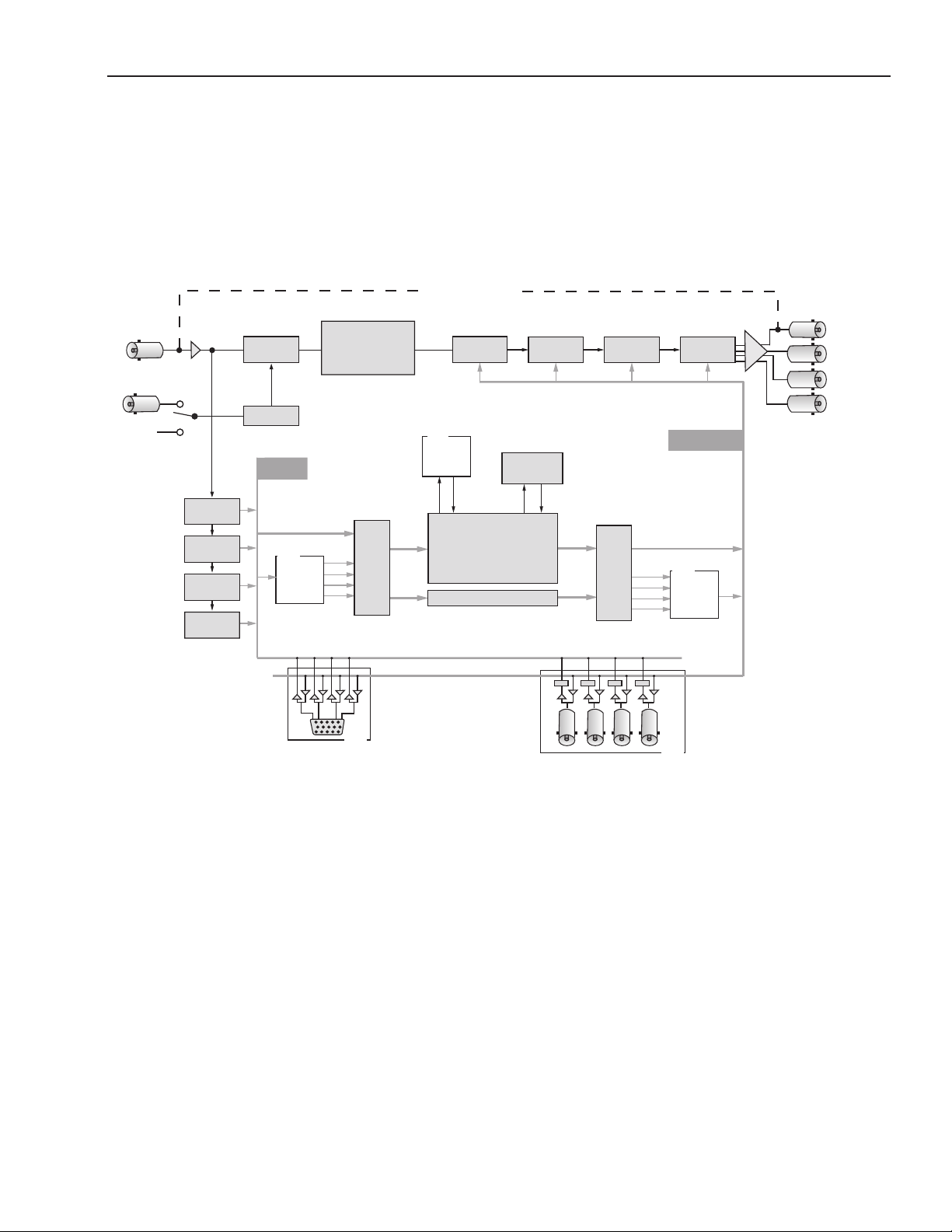
Functional Block Diagrams
For the Avenue 7555
Shown below is the functional block diagram for the Avenue 7555. The following two pages show the
functional block diagrams for the Avenue 9550 and 9550-XA.
HD/SD
SDI Input
Ref
Master
Ref
Group 1
Disembedder
Ch 1:4
Group 2
Disembedder
Ch 5:8
Group 3
Disembedder
Ch 9:12
Group 4
Disembedder
Ch 13:16
Frame
Store
Memory
Genlock
Input Bus
32 Sources
Option
7615
AC-3
Dolby D/E
Decoding
Video Processing
Gains
Pedestal
Legalizer
Input
Audio
Routing
Fail-safe Bypass
Group 1
Embedder
Ch 1:4
Option
9670
LevelTrack™
Audio AGC
16 x 16 Channel
Mixer / Combiner
Data Bypass
Group 2
Embedder
Ch 5:8
Memory Buffer
for Audio Delay
Group 3
Embedder
Ch 9:12
Output
Audio
Routing
SRC SRC SRC SRC
Group 4
Embedder
Ch 13:16
Output Bus
32 Destinations
Option
7630
AC-3
Dolby D/E
Encoding
Fail-safe
Output
HD/SD
SDI Outputs
9615 Audio Option Software Key Enables
4 Balanced Audio In/Out
Supports Dolby Metadata
Option
9615 Audio Option Software Key Enables
4 Independent AES3id Input/Output Ports
Option
Functional Block Diagram of the Avenue 7555
www.ensembledesigns.com Avenue 7555, 9550, 9550-XA - Page 15
Page 16
7555 HD/SD, 9550 3G/HD/SD, and 9550-XA 3G/HD/SD Video Processing Frame Synchronizers
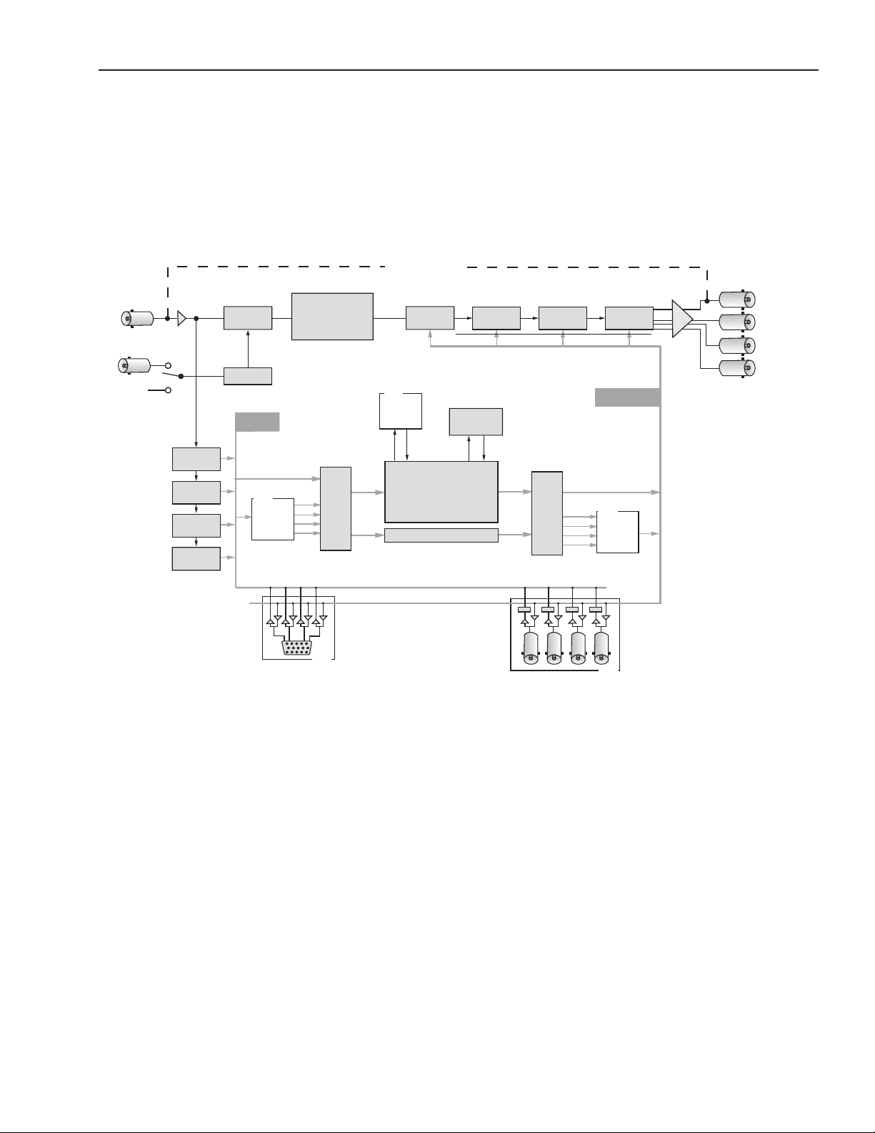
For the Avenue 9550
Shown below is the functional block diagram for the Avenue 9550. The 9550 is identical to the 7555
except for the 9550’s ability to accept 3G.
3G/HD/SD
SDI Input
Ref
Master
Ref
Group 1
Disembedder
Ch 1:4
Group 2
Disembedder
Ch 5:8
Group 3
Disembedder
Ch 9:12
Group 4
Disembedder
Ch 13:16
7615
AC-3
Video Processing
Gains
Pedestal
Legalizer
Input
Audio
Routing
Option
Frame
Store
Memory
Genlock
Input Bus
32 Sources
Option
Dolby D/E
Decoding
9615 Audio Option Software Key Enables
4 Balanced Audio In/Out
Supports Dolby Metadata
Fail-safe Bypass
Group 1
Embedder
Ch 1:4
Option
9670
LevelTrack™
Audio AGC
16 x 16 Channel
Mixer / Combiner
Data Bypass
Group 2
Embedder
Ch 5:8
Memory Buffer
for Audio Delay
Group 3
Embedder
Ch 9:12
Output
Audio
Routing
SRC SRC SRC SRC
9615 Audio Option Software Key Enables
4 Independent AES3id Input/Output Ports
Group 4
Embedder
Ch 13:16
Output Bus
32 Destinations
Option
7630
AC-3
Dolby D/E
Encoding
Option
Fail-safe
Output
3G/HD/SD
SDI Outputs
Functional Block Diagram of the Avenue 9550
www.ensembledesigns.com Avenue 7555, 9550, 9550-XA - Page 16
Page 17

7555 HD/SD, 9550 3G/HD/SD, and 9550-XA 3G/HD/SD Video Processing Frame Synchronizers
For the Avenue 9550-XA
Shown below is the functional block diagram for the Avenue 9550-XA. Relative to the 9550, the
9550-XA option adds two AES I/O ports and removes two SDI outputs. The 9550-XA option provides 12
channels of AES I/O and 2 SDI outputs.
3G/HD/SD
SDI Input
Ref
Master
Ref
Group 1
Disembedder
Ch 1:4
Group 2
Disembedder
Ch 5:8
Group 3
Disembedder
Ch 9:12
Group 4
Disembedder
Ch 13:16
Frame
Store
Memory
Genlock
Input Bus
32 Sources
Option
Dolby D/E
Decoding
9615 Audio Option Software Key Enables
Video Processing
Gains
Pedestal
Legalizer
Option
Input
Audio
Routing
7615
AC-3
4 Balanced Audio In/Out
Supports Dolby Metadata
Fail-safe Bypass
Group 1
Embedder
Ch 1:4
Option
9670
LevelTrack™
Audio AGC
16 x 16 Channel
Mixer / Combiner
Data Bypass
Group 2
Embedder
Ch 5:8
Memory Buffer
for Audio Delay
Output
Routing
SRC SRC
SRC SRC SRC SRC
9615 Audio Option Software Key Enables
6 Independent AES3id Input/Output Ports
Embedder
Audio
Group 3
Ch 9:12
Group 4
Embedder
Ch 13:16
Output Bus
32 Destinations
Option
7630
AC-3
Dolby D/E
Encoding
Option
Fail-safe
Output
3G/HD/SD
SDI Outputs
Functional Block Diagram of the Avenue 9550-XA
www.ensembledesigns.com Avenue 7555, 9550, 9550-XA - Page 17
Page 18
7555 HD/SD, 9550 3G/HD/SD, and 9550-XA 3G/HD/SD Video Processing Frame Synchronizers
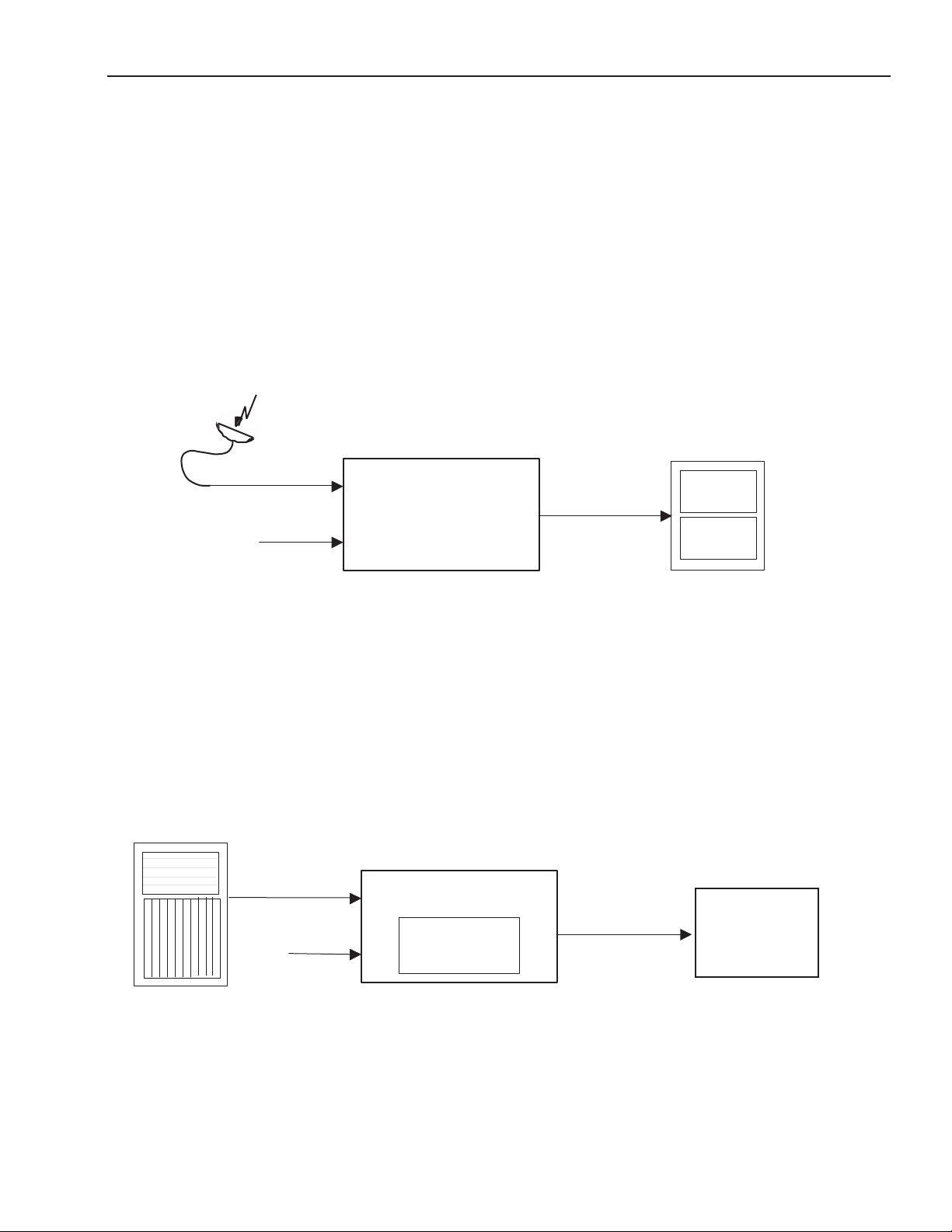
Applications
This section provides two typical applications for utilizing the versatility of the 7555, 9550 and 9550-XA
Video Processing and Frame Synchronizer modules.
Timing of an Asynchronous Input
As shown in the illustration below, the 7555 module can accept an asynchronous video input such
as the feed from a satellite receiver. The module can time the signal to a house reference, preserving
audio lip sync, and send the timed output to a router for distribution throughout the facility.
Satellite
Feed
Router
7555
House
Ref. In
HD or SD
Video with
Embedded Audio
7555 Module Timing an Asynchronous Satellite Input Signal
Embedding AES Audio and Adjusting Video with Internal Proc Amp
In the example shown below, the 9550 module is embedding AES audio into the SDI output of a
production switcher (requiring the 7630 and 9615 software key options). The Proc Amp function on
the 9550 is used to make final adjustments to the video which is then output to a video server.
3G, HD or SD
Production
Switcher
AES
Audio
9550
7630 and 9615
software key options
3G, HD or SD
Video with
Embedded Audio
Video
Server
9550 Module Embedding AES Audio into SDI and Making Proc Amp Adjustments
www.ensembledesigns.com Avenue 7555, 9550, 9550-XA - Page 18
Page 19

7555 HD/SD, 9550 3G/HD/SD, and 9550-XA 3G/HD/SD Video Processing Frame Synchronizers
Three Use Cases for the 9615 AES, Analog Audio, and Data I/O Software Key Option
The primary functions relating to the 9615 AES, analog audio, and data I/O software key option are
addressed in the following three use cases:
• Embedding (using the module as a multiplexer)
• Disembedding (using the module as a demultiplexer)
• In-line processing
Each use case is presented as a list of sequential steps. For further details about a specific process,
see the corresponding menu discussion. The menu references in each use case are linked to their
respective menu discussion pages. The overall menu discussion begins on page 24.
Embedding
These are the sequential steps to embedding:
1. Connect the video signal to the SDI In BNC input (page 12).
2. Route digital audio into the module through the AES BNC inputs; route analog audio through
the 15-pin D connector (page 12).
3. Select and configure the pathways of the incoming audio signals to go to the desired mixer
input channels by using the In 1:4, In 5:8, In 9:12, and In 13:16 menus (page 45).
4. If you are encoding audio signals into Dolby E or Dolby D/AC-3, select which mixer channels
you want to send to the encoder (up to four pairs) by using the Encoder menu (page 53).
5. Work with the mixer to configure gain levels, output bus assignments, Mix Mode selections,
and the LevelTrack Audio Loudness Control AGC software (optional) by using the Mix 1:4, Mix
5:8, Mix 9:12, and Mix 13:16 menus (page 41).
6. Determine which channel groups to embed into the outgoing SDI signal by using the Mux
Out menu (page 35).
7. If you are encoding audio signals into Dolby E or Dolby D/AC-3, use the Encoder Insert control
on the Mux Out menu to place the encoder output onto a pair of audio channels on the
outgoing SDI signal (page 35).
www.ensembledesigns.com Avenue 7555, 9550, 9550-XA - Page 19
Page 20

7555 HD/SD, 9550 3G/HD/SD, and 9550-XA 3G/HD/SD Video Processing Frame Synchronizers
Disembedding
These are the sequential steps to disembedding:
1. Connect the video signal with embedded audio to the SDI In BNC input (page 12).
2. If you are decoding a Dolby E or Dolby D/AC-3 audio signal, indicate which pair of channels
you want to decode by using the Decoder menu (page 51).
3. Route the decoded signal to the mixer by using the In 1:4, In 5:8, In 9:12, and In 13:16 menus
(page 44).
4. Route the disembedded audio to the mixer input channels by using the In 1:4, In 5:8, In 9:12,
and In 13:16 menus (page 44).
5. Work with the mixer to configure gain levels, Mix Mode selections, and LevelTrack Audio
Loudness Control AGC software (optional) by using the Mix 1:4, Mix 5:8, Mix 9:12, and Mix
13:16 menus (page 41).
6. Configure audio output using a combination of the mixer output bus assignments (page 42)
for digital audio output and the Aud Cfg menu (page 33) for analog audio output.
In-Line Processing
These are the sequential steps to in-line processing:
1. Connect the video signal with embedded audio to the SDI In BNC input (page 12).
2. If you are decoding a Dolby E or Dolby D/AC-3 audio signal:
• Indicate which pair of channels you want to decode by using the Decoder menu
(page 51).
• Route the decoded signal to the mixer by using the In 1:4, In 5:8, In 9:12 and In 13:16
menus (page 47).
3. Route the disembedded audio to the mixer input channels by using the In 1:4, In 5:8, In 9:12,
and In 13:16 menus (page 46).
4. Work with the mixer to configure gain levels, output bus assignments, Mix Mode selections,
and LevelTrack Audio Loudness Control AGC software (optional) by using the Mix 1:4, Mix 5:8,
Mix 9:12, and Mix 13:16 menus (page 41).
5. Determine which channel groups to embed into the outgoing SDI signal using the Mux Out
menu (page 35).
6. If you are encoding audio signals into Dolby E or Dolby D/AC-3, place the encoder output onto
a pair of audio channels on the outgoing SDI signal by using the Encoder Insert control on
the Mux Out menu (page 35).
www.ensembledesigns.com Avenue 7555, 9550, 9550-XA - Page 20
Page 21
7555 HD/SD, 9550 3G/HD/SD, and 9550-XA 3G/HD/SD Video Processing Frame Synchronizers
Module Configuration and Control
Avenue module parameters can be configured and controlled remotely from one or both of the
remote control options: the Avenue Touch Screen or the Avenue PC Application. Once the module
parameters have been set remotely, the information is stored on the module CPU. This allows
the module be moved to a different slot in the frame at your discretion without losing the stored
information.
Avenue PC Option
For setting the parameters remotely using the Avenue PC option, refer to the Avenue PC Remote
Configuration section of this document starting on page 24.
Avenue Touch Screen Option
The Avenue Touch Screen option works with the same menus and controls as the Avenue PC option.
Note: At this time, the mixer menus (Mix 1:4, Mix 5:8, Mix 9:12, Mix 13:16) do not
function with the Touch Screen interface. A pending software update will fix this
issue. However, all the mixer functionality is currently available through the Avenue
PC interface.
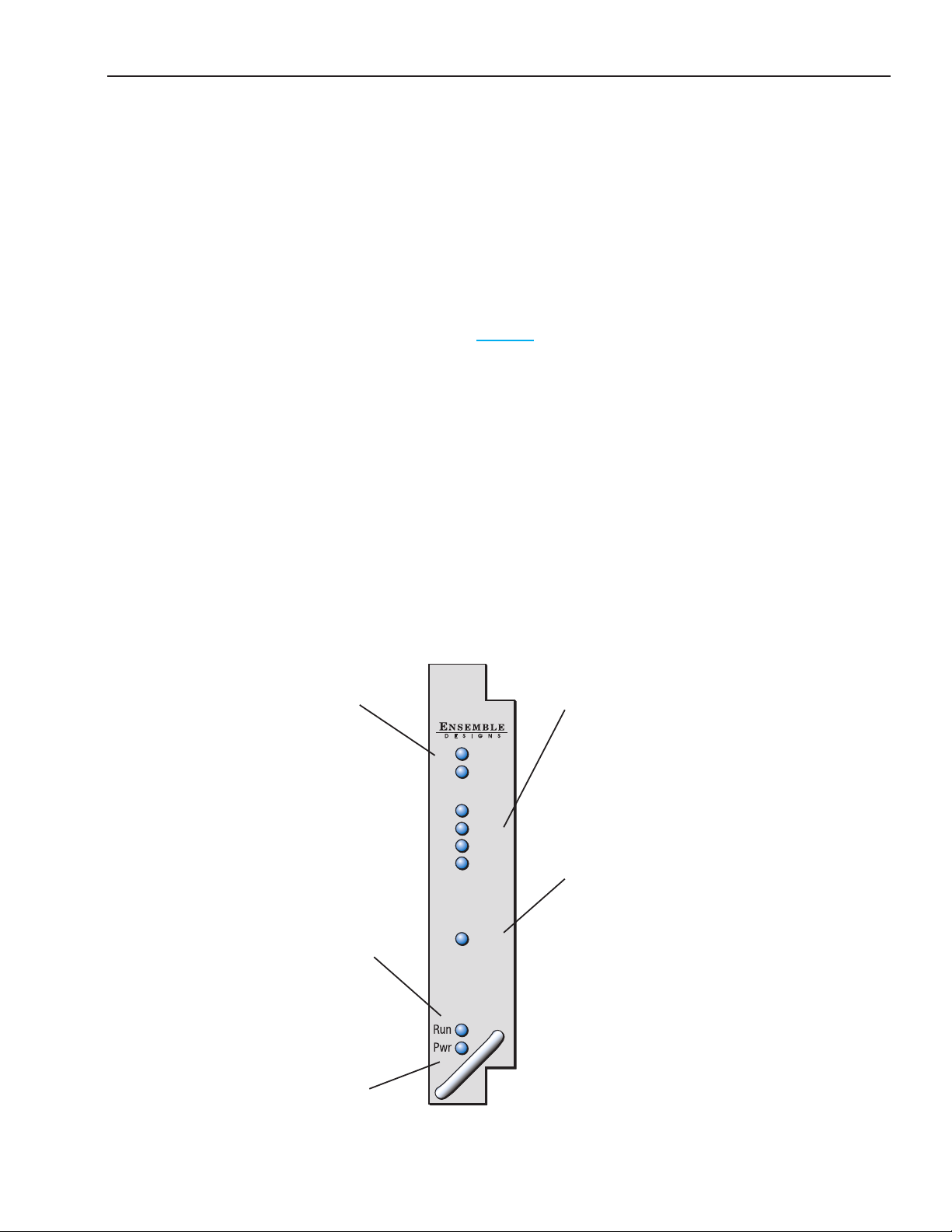
Front Panel Controls and Indicators
For the Avenue 7555
Each front edge indicator and switch setting is shown in the diagram below:
SDI In Video and Audio green
LEDs: One or both LEDs will light
to indicate which type of
signal is currently being detected.
OFF when a signal is not
detected.
Run green LED:
OFF: A power fault or halted CPU
ON: A halted CPU
FAST BLINK: CPU Run error
SLOW BLINK: System OK. (If
SPI control is active from the
main frame System Control
Module, all Run indicators will be
synchronized.)
7555
HD/SD
Video Audio
Processor
SDI InAES Audio
Video
Audio
1/2 In
3/4 In
5/6 In
7/8 In
Ref In
AES Audio green LEDs:
For each pair of AES audio
channels, the LED will light when
there is a valid AES input on the
corresponding BNC rear
connector and that AES signal
has been selected as an input to
the mixer or to the decoder.
OFF if a pair of AES audio
channels has no input or if it is
being used as an output.
Ref green LED:
ON when Reference input is
detected and locked.
OFF when no Reference input is
detected.
Pwr green LED:
Indicates the presence (ON) or
absence (OFF) of power (+5V).
www.ensembledesigns.com Avenue 7555, 9550, 9550-XA - Page 21
Page 22

7555 HD/SD, 9550 3G/HD/SD, and 9550-XA 3G/HD/SD Video Processing Frame Synchronizers
For the Avenue 9550
Each front edge indicator and switch setting is shown in the diagram below:
SDI In Video and Audio green
LEDs: One or both LEDs will light
to indicate which type of
signal is currently being detected.
OFF when a signal is not
detected.
Run green LED:
OFF: A power fault or halted CPU
ON: A halted CPU
FAST BLINK: CPU Run error
SLOW BLINK: System OK. (If
SPI control is active from the
main frame System Control
Module, all Run indicators will be
synchronized.)
9550
3G/HD/SD
Video Audio
Processor
Video
Audio
SDI InAES Audio
1/2 In
3/4 In
5/6 In
7/8 In
Ref In
AES Audio green LEDs:
For each pair of AES audio
channels, the LED will light when
there is a valid AES input on the
corresponding BNC rear
connector and that AES signal
has been selected as an input to
the mixer or to the decoder.
OFF if a pair of AES audio
channels has no input or if it is
being used as an output.
Ref green LED:
ON when Reference input is
detected and locked.
OFF when no Reference input is
detected.
Pwr green LED:
Indicates the presence (ON) or
absence (OFF) of power (+5V).
www.ensembledesigns.com Avenue 7555, 9550, 9550-XA - Page 22
Page 23

7555 HD/SD, 9550 3G/HD/SD, and 9550-XA 3G/HD/SD Video Processing Frame Synchronizers
For the Avenue 9550-XA
Each front edge indicator and switch setting is shown in the diagram below:
SDI In Video and Audio green
LEDs: One or both LEDs will light
to indicate which type of
signal is currently being detected.
OFF when a signal is not
detected.
Run green LED:
OFF: A power fault or halted CPU
ON: A halted CPU
FAST BLINK: CPU Run error
SLOW BLINK: System OK. (If
SPI control is active from the
main frame System Control
Module, all Run indicators will be
synchronized.)
9550-XA
3G/HD/SD
Video Audio
Processor
Video
Audio
SDI InAES Audio
1:2 In
3:4 In
5:6 In
7:8 In
9:10 In
11:12 In
Ref In
AES Audio green LEDs:
For each pair of AES audio
channels, the LED will light when
there is a valid AES input on the
corresponding BNC rear
connector and that AES signal
has been selected as an input to
the mixer or to the decoder.
OFF if a pair of AES audio
channels has no input or if it is
being used as an output.
Ref green LED:
ON when Reference input is
detected and locked.
OFF when no Reference input is
detected.
Pwr green LED:
Indicates the presence (ON) or
absence (OFF) of power (+5V).
www.ensembledesigns.com Avenue 7555, 9550, 9550-XA - Page 23
Page 24

7555 HD/SD, 9550 3G/HD/SD, and 9550-XA 3G/HD/SD Video Processing Frame Synchronizers
Avenue PC Remote Configuration
The Avenue PC remote control status menu for this module is illustrated and explained below. Refer
to each menu’s description in the following pages for a summary of available parameters that can be
set remotely through the menus illustrated. For more information on using Avenue PC, refer to the
Avenue PC Control Application Software data pack that came with the option.
Parameter fields that are grayed out can indicate one of the following conditions:
• An option is not installed.
• The function is not active.
• The module is locked.
• The User Level set with Avenue PC does not permit access.
Avenue PC and Avenue Touch Screen Menus
Input Menu
Signal Types Accepted by 7555
The 7555 module accepts these signal types:
HD Serial Digital 1.485 Gb/s, SMPTE 274M, 292M or 296M
SD Serial Digital 270 Mb/s, SMPTE 259M
Data as per SMPTE 337M
Signal Types Accepted by 9550 and 9550-XA
In addition to accepting the same signal types as the 7555, the 9550 and 9550-XA modules also
accept:
HD Serial Digital 2.97 Gb/s, SMPTE 424M, 425M
Incoming Video Signal Reporting
Connect the video signal with or without embedded audio to the SDI In BNC input. The Input menu
reports the video format and frame rate detected. The Input menu example shown on the next page
indicates that there is video coming in with a video format of 1080i and a frame rate of 59.94.
The Input menu provides essential reference information regarding what is going on with the
incoming video signal with respect to the groups and channels. The module detects and reports the
presence or absence of embedded data and/or audio through the Input menu’s Grp 1 Status, Grp
2 Status, Grp 3 Status and Grp 4 Status reporting fields. “D” designates data; “A” designates audio; a
dash means that there is no embedded content.
www.ensembledesigns.com Avenue 7555, 9550, 9550-XA - Page 24
Page 25

7555 HD/SD, 9550 3G/HD/SD, and 9550-XA 3G/HD/SD Video Processing Frame Synchronizers
For example, in the Input menu shown below, the Grp 1 Status shows “1/2:A 3/4:A” indicating
that channels 1 through 4 contain embedded audio. Grp 2 Status and Grp 3 Status also show the
presence of embedded audio in channels 5 through 8 and 9 through 12. Grp 4 Status, displaying
“13/14:- 15/16:-” indicates that channels 13 through 16 do not contain embedded content.
Strip Audio Checkbox
When disembedding, you can use the Strip Audio checkbox to remove all embedded audio from the
incoming video signal.
For embedding, the Strip Audio checkbox is a tool to prevent accidental group conflicts. The safest
method of embedding is to first strip any embedded audio that is already present in the incoming
signal by clicking the Strip Audio checkbox. Following that, you can re-embed the channels you want
to keep.
Although it is recommended to use the Strip Audio checkbox, it is not strictly necessary if you are
certain that you do not have any conflicting groups. For example, if only group 1 is present on the
input, you could embed groups 2, 3 and 4 without first stripping group 1. However, if you embed
group 1 when group 1 is already present, the result will be problematic.
Input Avenue PC Menu showing the presence of video and embedded audio. This
example also shows that Group 4 (channels 13 through 16) does not have embedded
content.
www.ensembledesigns.com Avenue 7555, 9550, 9550-XA - Page 25
Page 26

7555 HD/SD, 9550 3G/HD/SD, and 9550-XA 3G/HD/SD Video Processing Frame Synchronizers
Input Touch Screen Menu showing the presence of video and embedded
audio. This example also shows that Group 4 (channels 13 through 16)
does not have embedded content.
www.ensembledesigns.com Avenue 7555, 9550, 9550-XA - Page 26
Page 27

7555 HD/SD, 9550 3G/HD/SD, and 9550-XA 3G/HD/SD Video Processing Frame Synchronizers
Reference Menu
Setting the Reference Input Source
The module genlocks to either composite video (PAL or NTSC) or to HD Tri-Level Sync. The module can
lock to the frame’s master reference or reference can be connected directly to the module’s external
Ref In BNC.
• Ref Source – Use the Ref Source control to set the reference input source. Select from one of
the following: Master Ref, Ext Ref, Self Ref.
• Reference – Reports the status of the reference input as either No Reference, Ref 525, Ref 625,
or Ref 1080i/60 TLS.
Reference Avenue PC Menu showing Master Ref selected. The Reference eld
displays Ref 525.
Reference Avenue Touch Screen Menu showing Self Ref selected as the
Reference Source. The Reference eld displays Ref 1080i/60 TLS.
www.ensembledesigns.com Avenue 7555, 9550, 9550-XA - Page 27
Page 28

7555 HD/SD, 9550 3G/HD/SD, and 9550-XA 3G/HD/SD Video Processing Frame Synchronizers
Timing Menu
Configuring the Frame Synchronizer
A Frame Synchronizer is used to synchronize the timing of a video signal to coincide with a timing
reference, such as a color black signal that is distributed throughout a facility. The synchronizer
accomplishes this by writing the incoming video into a frame memory buffer under the timing
direction of the sync information contained in the reference video. Simultaneously, the synchronizer’s
timing system reads back the memory that is genlocked to a house reference.
As a result, the timing or alignment of the video frame can be adjusted so that the scan of the upper
left corner of the image is happening simultaneously on all sources. This is a requirement for both
analog and digital systems in order to perform video effects or switch glitch-free in a router.
Use the Timing Menu shown on the next page to adjust the following parameters:
• Frame Sync – Turn the Frame Sync function on or off.
• Frame Delay – For asynchronous inputs, set the amount of frame delay desired up to one
second.
The Vertical and Horizontal Timing controls adjust the timing of the video signal relative to the timing
reference. Setting the Vertical and Horizontal parameters to 0 (the default setting) will “zero” time the
video signal to the reference. Negative values will cause the video signal to be early with respect to the
reference. Positive values will make the video signal later in time with respect to the reference.
• Vertical Timing – When the Frame Sync is on, adjust the vertical timing of the output signal to
place the leading edge of sync to coincide with other sources.
• Horizontal Timing – When the Frame Sync is on, adjust the horizontal timing of the output
signal to place the leading edge of sync to coincide with other sources.
www.ensembledesigns.com Avenue 7555, 9550, 9550-XA - Page 28
Page 29

7555 HD/SD, 9550 3G/HD/SD, and 9550-XA 3G/HD/SD Video Processing Frame Synchronizers
Timing Avenue PC Menu
Timing Avenue Touch Screen Menu
www.ensembledesigns.com Avenue 7555, 9550, 9550-XA - Page 29
Page 30

7555 HD/SD, 9550 3G/HD/SD, and 9550-XA 3G/HD/SD Video Processing Frame Synchronizers
Proc Menu
Adjusting Video Processing Parameters
Video Gain, Chroma, Pedestal and Hue are standard Proc Amp controls affecting the entire video
signal. Use the Proc Menu shown on the next page to adjust these video processing parameters for
the signal:
• Gain – Adjust the percentage of overall gain (luminance and chrominance).
• Chroma – Adjust the percentage of chroma amplitude, which is the color or chroma content
of a signal, consisting of the hue and saturation of the image.
• Pedestal – Adjust the pedestal (black) level of the signal in IRE. The IRE scale is used to
measure the video level, where 0 IRE is black and 100 IRE is full white. The actual voltages that
these levels correspond to can vary between formats.
• Hue – Adjust the hue of the signal ± 180 degrees. The Hue control gives phase rotation of the
color vectors in the manner of an NTSC composite Proc Amp.
www.ensembledesigns.com Avenue 7555, 9550, 9550-XA - Page 30
Page 31

7555 HD/SD, 9550 3G/HD/SD, and 9550-XA 3G/HD/SD Video Processing Frame Synchronizers
Proc Avenue PC Menu
Proc Avenue Touch Screen Menu
www.ensembledesigns.com Avenue 7555, 9550, 9550-XA - Page 31
Page 32

7555 HD/SD, 9550 3G/HD/SD, and 9550-XA 3G/HD/SD Video Processing Frame Synchronizers
Aud Stat Menu
Reporting Audio Input Sync Status
The Aud Stat menu reports the status of audio input for each pair of channels.
In the Avenue PC example below, channels 1/2 and 9/10 show a status of “Data Sync,” meaning
that these two pairs of audio channels containing embedded data are synchronous with the video.
Channels 3/4, 5/6, 7/8, 11/12 show a status of “Audio Sync,” meaning that these four pairs of audio
channels are synchronous with the video. Channels 13/14 and 15/16 indicate that there is not any
input.
The Avenue Touch Screen example below shows that all of the audio channels are synchronous with
the video.
Aud Stat Avenue PC Menu
Aud Stat Avenue Touch Screen Menu
www.ensembledesigns.com Avenue 7555, 9550, 9550-XA - Page 32
Page 33

7555 HD/SD, 9550 3G/HD/SD, and 9550-XA 3G/HD/SD Video Processing Frame Synchronizers
Aud Cfg Menu
Configuring Analog Audio Outputs and LevelTrack Audio Loudness Control AGC
Software Option
Use the Aud Cfg menu to configure up to four channels of analog audio output. Analog audio goes
out through the 15-pin D connector. Digital and analog audio paths may be used simultaneously.
Important! Before you can use the 15-pin D connector for analog audio, you must first install
jumper connectors onto the 7555 board. See “Configuring the Analog Audio and Balanced Digital
Data Jumper Connectors” on page 10 for details.
For configuring digital audio output, see “Configuring Digital Audio Outputs (9615 Software Key
Option Required)” on page 43.
From the Anlg Out 1/2 drop-down control, select the pair of mixer channels that you want to send
out through analog channels 1/2. Select the pair of mixer channels that you want to send out through
analog channels 3/4 from the Anlg Out 3/4 drop-down control.
• Anlg Ref Level – Set the Analog Reference Level from -10 dB to +4 dB for the analog audio
output.
• Dig Ref Level – Digital Audio Reference Level. Applies to AES digital. -20dBFS or -18dBFS.
• Audio Delay – Audio Delay can be adjusted from 0 to 1000 milliseconds (mSec).
Meter Mode
Select between LKFS and dBFS. This selection determines the method by which the audio is analyzed
and measured, and will impact how Audio AGC behaves.
• LKFS – LKFS (Loudness K-weighted relative to Full Scale) is a loudness amplitude level based on
the ITU-R BS.1770 Loudness Measurement Method. It is a scale for audio measurement similar to
VU or Peak, but rather than measuring gain, it measures perceived loudness. Based on a complex
algorithm, this method takes into account audio processing that increases perceived loudness
without increasing gain. LKFS is the measurement method required to comply with the
Calm Act.
• dBFS – dBFS (Decibels relative to Full Scale) is a more traditional method used for measuring audio
volume. For more information on decibels and dBFS, please refer to the “Glossary” on page 61.
Meter Position
The Meter Position effects both the Final Average (yellow line) on the AGC chart and the audio input
level for the 9690 Audio Compliance and Monitoring Software. The Meter Position is factory set to
Post.
• Pre (pre-fader) – When Pre is selected, the Final Average (yellow line) on the AGC chart will
not reflect any manual adjustments made in the mixer to the gain level of the channel being
monitored. Similarly, the chart and recording in the 9690 Audio Compliance and Monitoring
Software will reflect the audio input level coming from your source prior to any gain or
attenuation being applied in the mixer.
• Post (post-fader) – When Post is selected, the Final Average (yellow line) on the AGC chart
reflects manual adjustments made in the mixer to the gain level of the channel being monitored.
Similarly, the chart and recording in the 9690 Audio Compliance and Monitoring Software
www.ensembledesigns.com Avenue 7555, 9550, 9550-XA - Page 33
Page 34

7555 HD/SD, 9550 3G/HD/SD, and 9550-XA 3G/HD/SD Video Processing Frame Synchronizers
reflect the audio input level coming from your source after any gain or attenuation is applied in
the mixer.
LKFS Average Time
Use this control to set the amount of time used to determine the LKFS or dBFS average. 10 seconds is a
typical setting.
Note: Although the control is labeled ”LKFS Avg Time,” if you have selected dBFS as your
meter mode, the LKFS Avg time control will actually be reflecting dBFS Avg time.
Aud Cfg Avenue PC Menu
Aud Cfg Avenue Touch Screen Menu
www.ensembledesigns.com Avenue 7555, 9550, 9550-XA - Page 34
Page 35

7555 HD/SD, 9550 3G/HD/SD, and 9550-XA 3G/HD/SD Video Processing Frame Synchronizers
Mux Out Menu
Selecting the Audio Channels to Embed into the Outgoing SDI Signal
From the Mux Out menu, you can determine which mixer channels are embedded back into the
outgoing SDI signal.
In the drop-down controls shown below, Embed Grp 1 represents embedded channels 1 through
4 and is associated with mixer outputs 1 through 4. Similarly, Embed Grp 2 represents embedded
channels 5 through 8, and is associated with mixer outputs 5 through 8; Embed Grp 3 represents
embedded channels 9 through 12, fed by mixer outputs 9 through 12; Embed Grp 4 represents
embedded channels 13 through 16, fed by mixer outputs 13 through 16. Select On for each group of
audio channels that you want to embed.
Embedded audio channels may go out of the module through as many as three paths—through the
SDI signal, through the AES outputs and through the analog audio outputs.
The 9615 AES and analog audio I/O software key option is required if you want to use the AES or
analog inputs and outputs.
Note: If an AES port is configured as an input, it cannot simultaneously function as an
output; that would create a conflict.
Mux Out Avenue PC Menu showing Embed Groups 1 - 4 turned on.
Placing the Encoder Output
The Encoder output stream occupies two channels on the outgoing SDI signal. Use the Encoder Insert
control on the Mux Out menu to tell the Encoder on which pair of audio channels you want to place
the encoded audio for the outgoing SDI. Available selections are:
Channels 1/2, 3/4, 5/6, 7/8, 9/10, 11/12, 13/14, 15/16.
www.ensembledesigns.com Avenue 7555, 9550, 9550-XA - Page 35
Page 36

7555 HD/SD, 9550 3G/HD/SD, and 9550-XA 3G/HD/SD Video Processing Frame Synchronizers
For example, the Encoder output stream will occupy channels 1/2 when 1/2 is selected from the
Encoder Insert control. The Encoder output stream may also go out through an AES port as long as
that AES port is not already being used as an input to the module.
The 7615, 7630 and 7635 sub modules and software key options are required for Dolby decoding and
encoding.
Mux Out Avenue PC Menu showing Embed Groups 1 - 4 turned on; also showing the
selections available from the Encoder Insert drop-down control.
Mux Out Avenue Touch Screen Menu
www.ensembledesigns.com Avenue 7555, 9550, 9550-XA - Page 36
Page 37

7555 HD/SD, 9550 3G/HD/SD, and 9550-XA 3G/HD/SD Video Processing Frame Synchronizers
Aud AGC Menu
The LevelTrack Audio Loudness Control AGC option adds an operator configurable audio level
management system to Avenue signal processing modules. LevelTrack will correct mismatched
audio levels between different program sources or segments within a program. Errors of this type are
regrettably common due to inconsistencies between different providers and program elements.
LevelTrack will automatically monitor the levels in up to 16 audio channels. Based upon the history
in each channel, LevelTrack applies gradual changes to prevent the audio level from dropping below
or exceeding user-programmable thresholds. The operator can apply this automatic level control to
an individual channel, a stereo pair, or surround channels. By adjusting the overall level of the signal
rather than masking the errors with compression, LevelTrack will not upset the internal dynamics of
the program material.
LevelTrack Configuration
Operators can perform all of the configuration for LevelTrack Audio Loudness Control AGC from the
Aud AGC menu. The following is a detailed description of the LevelTrack Audio Loudness Control AGC
controls and how they are used:
AGC Master
• Off – When set to Off the LevelTrack Loudness Control AGC functions are turned off. At the
moment that LevelTrack Loudness Control is switched off it will smoothly reduce the gain or
attenuation (if any) that it had been applying.
• On – When set to On, the LevelTrack Loudness Control system engages. It will use the measured
dBFS or LKFS of the incoming signal to determine how much gain or attenuation should be
applied.
Final Gain
This status indicator shows how much correction, either gain or attenuation, the LevelTrack Loudness
Control system is applying.
Silence Limit
0 to -70, factory set to -40 LKFS.
Use this control to establish the value for what is considered to be silence. For example, when set to
the value of -40 LKFS, levels that are at and below that value are treated as silence.
Target Level
0 to -50, factory set to -24 LKFS.
The Target Level setting establishes the target output audio level. The LevelTrack Loudness Control
AGC function will automatically apply gain or attenuation to the signal to bring it within the range
defined by the Target Level and the Spread.
Note: LKFS is interpreted as the inverse of Dialnorm. For example, if your goal is to output
Dialnorm 24, set your Target Level at -24.
www.ensembledesigns.com Avenue 7555, 9550, 9550-XA - Page 37
Page 38

7555 HD/SD, 9550 3G/HD/SD, and 9550-XA 3G/HD/SD Video Processing Frame Synchronizers
Spread
0 to 50, factory set to 1 LKFS.
Set the Spread from x to x. The Spread indicates how far above and below the Target Level you want
to allow the AGC to go. A typical setting is 1. If, for example, the Target Level is set at -24 LKFS, and the
Spread is set at 1, the AGC will aim to keep the output signal between -25 and -23 LKFS.
Transition Time
0.5 sec to 30 sec, factory set to 3 seconds.
This setting controls how rapidly LevelTrack Loudness Control will make adjustments once it
determines that a change is needed.
Max Atten
0 dB to -12 dB, factory set to -12 bB.
This control sets the maximum amount of attenuation that LevelTrack Loudness Control can use to
reduce audio levels.
Max Gain
0 dB to +12 dB, factory set to 12 bB.
This control sets the maximum amount of gain that LevelTrack Loudness Control can apply to the
input in order to raise audio levels.
Taken as a whole, these controls provide tremendous flexibility in both how LevelTrack Loudness
Control AGC is configured and in how audio is perceived by the listener.
www.ensembledesigns.com Avenue 7555, 9550, 9550-XA - Page 38
Page 39

7555 HD/SD, 9550 3G/HD/SD, and 9550-XA 3G/HD/SD Video Processing Frame Synchronizers
Aud AGC Avenue PC Menu
Aud AGC Avenue Touch Screen Menu
www.ensembledesigns.com Avenue 7555, 9550, 9550-XA - Page 39
Page 40

7555 HD/SD, 9550 3G/HD/SD, and 9550-XA 3G/HD/SD Video Processing Frame Synchronizers
Chart
Click the Chart button to view a visual representation of AGC behavior on a channel-by-channel basis.
The chart represents the most recent two-minute span of time for analysis performed on the channel
selected in the CH Sel drop-down menu.
• In Audio Level (red line): The red line represents the level of the audio signal as it enters the
Avenue module, prior to being processed by AGC.
• Average Level (green line): The green line represents an averaging of the incoming audio signal
level.
• Final Gain (blue line): The blue line represents the Final Gain expressed in terms of decibels (dB).
This shows how much the AGC is adjusting the level of the audio signal based on the configuration
parameters specified in the Aud AGC menu.
• Final Average (yellow line): The yellow line represents the final corrected output, calculated from
the Average Level and the Final Gain. The yellow line reflects manual adjustments made to the
gain level on the mixer for the channel being charted, provided that the Meter Position is set to
Post on the Aud Cfg menu.
• CH Sel drop-down menu: LevelTrack Loudness Control automatically monitors the levels in up to
16 audio channels. From the drop-down menu, select the channel for which you want to view the
LevelTrack Loudness Control AGC behavior.
Note: The Chart’s graph lines remain active as long as you are looking at the corresponding
module on Avenue PC. However, if you keep the chart window open, and then select
a different Avenue module through Avenue PC, the chart’s graph lines will go flat.
AGC is still active, however, until it is turned off in the AGC Master drop-down menu.
Aud AGC Chart
www.ensembledesigns.com Avenue 7555, 9550, 9550-XA - Page 40
Page 41

7555 HD/SD, 9550 3G/HD/SD, and 9550-XA 3G/HD/SD Video Processing Frame Synchronizers
Mix 1:4, Mix 5:8, Mix 9:12, Mix 13:16 Menus
Note: At this time, the mixer menus (Mix 1:4, Mix 5:8, Mix 9:12, Mix 13:16) do not
function with the Touch Screen interface. A pending software update will fix this
issue. However, all the mixer functionality is currently available through the Avenue
PC interface.
Mix 1:4 Avenue PC Menu
One common method of working with the mixer is to put the signals through unchanged, using
the mixer only to indicate out bus assignments. However, you can also associate channels with one
another.
Combinations of Input Channels
Any particular channel can be independent or it can be tied to other channels. When multiple
channels are associated together, it affects their behavior with respect to gain control, loudness
measurement, and the LevelTrack Audio Loudness Control AGC option.
www.ensembledesigns.com Avenue 7555, 9550, 9550-XA - Page 41
Page 42

7555 HD/SD, 9550 3G/HD/SD, and 9550-XA 3G/HD/SD Video Processing Frame Synchronizers
The Mix Mode drop-down control provides the following four approaches for working with the
channels:
Mix Mode Mixer Behavior
1. Normal Working with mixer channels independently is the default or “Normal’
mix mode.
2. Paired If you want two channels to be paired so that altering the gain of one
will automatically alter the gain of the other, choose Paired from the Mix
Mode drop-down control for one of the channels you want to pair; for
example, channel 9 and 10 will be paired with each other if you select
Paired for one of those channels.
3. Surround Sound 5.1 For surround sound 5.1, which uses 6 channels, specify for each channel
one of these 6 selections from the Mix Mode drop-down control.
For example:
Input Ch 1 = Multi Left
Input Ch 2 = Multi Right
Input Ch 3 = Multi Center
Input Ch 4 = Multi L Surr
Input Ch 5 = Multi R Surr
Input Ch 6 = Multi Bass
4. Surround Sound 7.1 For surround sound 7.1, which uses 8 channels, specify for each channel
one of the above 6 selections plus two additional Mix Mode selections.
For example:
Input Ch 7 = Multi L Rear
Input Ch 8 = Multi R Rear
Once you have established a pairing or surround sound grouping, changing the gain on one channel
affects all of the associated channels. Also, AGC processing (if enabled) will take into account any
channel pairs or surroud sound groupings.
Any 8 channels may take the input from the Dolby E decoder, leaving 8 remaining input channels to
assign.
Out Bus Assignments
The mixer has 16 input channels and 16 output busses. Initially, each channel is assigned a separate
output bus. For example, by default, mixer input channel 1 is assigned to mixer output bus 1, indicated
by the green button in the Input Ch 1 control. However, you can assign multiple input channels to go
to the same output bus. Or you can have each input channel going to multiple output busses (from 0
to 16).
Each mixer channel has a level control on its input. There is not a separate output gain level control.
www.ensembledesigns.com Avenue 7555, 9550, 9550-XA - Page 42
Page 43

7555 HD/SD, 9550 3G/HD/SD, and 9550-XA 3G/HD/SD Video Processing Frame Synchronizers
Automatic Gain Control (AGC) (Optional)
For any mixer channel, you can enable AGC by selecting the AGC Enabled box. When enabled, the AGC
Enabled box displays green. Note, however, that the AGC Enabled control will have no effect unless
AGC is first engaged. To turn on the AGC function, select Auto from the AGC Master control in the Aud
AGC menu (page 37).
Configuring Audio Output (9615 Software Key Option Required)
From the output of the mixer, you can send digital audio out through the 4 AES connectors (6 AES
connectors for the 9550-XA module). Analog audio goes out through the 15-pin D connector. The
digital and analog audio paths may be used simultaneously. You may also re-embed the audio.
Configuring Digital Audio Outputs (9615 Software Key Option Required)
Use the Out Bus Assign controls from the Mix 1:4, Mix 5:8, Mix 9:12 and Mix 13:16 menus to route
mixer inputs to mixer outputs. For digital audio, mixer output pair 1/2 feeds SDI out 1/2 and/or AES out
1/2. Mixer output pair 3/4 feeds SDI out 3/4 and/or AES out 3/4, and so on.
Note: If an AES connector is selected as an input, it cannot simultaneously be used as an
output.
www.ensembledesigns.com Avenue 7555, 9550, 9550-XA - Page 43
Page 44

7555 HD/SD, 9550 3G/HD/SD, and 9550-XA 3G/HD/SD Video Processing Frame Synchronizers
In 1:4, In 5:8, In 9:12, In 13:16 Menus
Selecting Audio Input Type and Routing to Mixer Input Channels
Use the In 1:4, In 5:8, In 9:12, and In 13:16 menus to select the type of audio input (SDI, AES, Analog,
or Decode) for each pair of input channels, and to direct them to a specific pair if mixer inputs. The
menus In 1:4, In 5:8, In 9:12 and In 13:16 correspond to mixer input channels 1 through 4, 5 through
8, 9 through 12 and 13 through 16, respectively. These four menus work in the same manner.
Using the In 1:4 menu as an example, when SDI is selected from the 1/2 Input drop-down control,
the following eight pairs of SDI channel selections are available in the control to its right: 1/2, 3/4, 5/6,
7/8, 9/10, 11/12, 13/14, 15/16. This reflects the 16 channels of audio that an SDI signal is capable of
carrying.
When AES is selected from the 1/2 input drop-down control, the following four pairs of AES channel
selections are available in the control to its right: 1/2, 3/4, 5/6, 7/8. This reflects the four AES connectors
available. Each AES connector can carry one pair of channels. (The 9550-XA has two additional AES
connectors, providing a total of six pairs of AES channels: 1/2, 3/4, 5/6, 7/8, 9/10, 11/12.)
When Analog is chosen, two pairs of channel choices are available: 1/2 and 3/4. This reflects the
capacity of the module to carry up to four channels of analog audio through the 15-pin D connector.
When Decode is selected, the following four choices are available: 1/2, 3/4, 5/6 and 7/8. When
decoding a Dolby D/AC-3 stream, a maximum of six channels are decoded. When decoding a Dolby E
stream, a maximum of eight channels are decoded.
Digital audio enters the module through either the SDI In connector or through the four AES inputs
(six AES inputs for the 9550-XA). Up to two pairs or four channels of analog audio enter the module
through the 15-pin D connector. A pair of wires carries one analog audio channel.
In 1:4 Avenue PC Menu
www.ensembledesigns.com Avenue 7555, 9550, 9550-XA - Page 44
Page 45

7555 HD/SD, 9550 3G/HD/SD, and 9550-XA 3G/HD/SD Video Processing Frame Synchronizers
Using the In 1:4, In 5:8, In 9:12, In 13:16 Menus for Embedding
Routing the Audio into the Module
Route the audio into the module through the AES BNC inputs (for digital audio) and/or through the
15-pin D connector (for analog audio).
Important! Before you can use the 15-pin D connector for analog audio, you must first install
jumper connectors onto the board. See Conguring the Analog Audio and Balanced Digital Data
Jumper Connectors on page 10 for details.
Selecting and Configuring Incoming Audio Pathways to the Mixer
Use the In 1:4, In 5:8, In 9:12 and In 13:16 menus to tell the module to which mixer channels you
want to direct each pair of audio channels. In this example, we are referencing the In 1:4 menu.
However, the same principles apply to the In 5:8, In 9:12 and In 13:16 menus.
For embedding, select AES or Analog for the 1/2 Input and 3/4 Input controls. With the corresponding
drop-down controls to the right, select the pair of audio channels that you want to send to mixer input
channels 1/2 and 3/4. In the example shown below, audio channels 5/6 from the incoming AES signal
will go to mixer input channels 1/2. Similarly, audio channels 7/8 from the incoming AES signal will go
to mixer input channels 3/4.
In 1:4 Avenue PC Menu from the 7555 and 9550 modules showing audio being directed
from AES connectors 5/6 and 7/8 to mixer input channels 1/2 and 3/4. The 9550-XA
module oers two additional pairs (9/10, 11/12) of AES channels.
www.ensembledesigns.com Avenue 7555, 9550, 9550-XA - Page 45
Page 46

7555 HD/SD, 9550 3G/HD/SD, and 9550-XA 3G/HD/SD Video Processing Frame Synchronizers
Using the In 1:4, In 5:8, In 9:12, In 13:16 Menus for Disembedding
Routing Disembedded Audio to Mixer Input Channels
The 7555, 9550 and 9550-XA modules provide both digital and analog pathways for the audio signal.
In a disembedding process, digital audio enters the module as embedded audio in the incoming SDI
video signal.
For the In 1:4 menu shown below, the pair of 1/2 Input drop-down controls work together to control
what is being sent to mixer input channels 1 and 2. The same is true for the pair of 3/4 Input dropdown controls. The choices available in the control to the right depend on the selection you make
from the control on the left. In this example, when SDI is selected from the control on the left, the
choices available from the control on the right are eight pairs of channels (1/2, 3/4, 5/6, 7/8, 9/10,
11/12, 13/14, 15/16), since there are up to 16 channels of embedded audio that may be available in an
incoming SDI video signal.
For disembedding, select SDI from the drop-down menus on the left side under 1/2 Input and 3/4
Input. With the corresponding drop-down controls to the right, specify which pair of embedded audio
channels from the SDI signal that you want to send to mixer input channels 1/2 and 3/4.
For example, in the instance shown below, channels 5 and 6 of the SDI embedded audio are being
directed to mixer input channels 1 and 2, while channels 7 and 8 of the SDI embedded audio are being
directed to mixer input channels 3 and 4.
In 1:4 Avenue Touch Screen Menu showing selected SDI embedded
audio channels that are being disembedded and directed to mixer
input channels 1/2 and 3/4.
www.ensembledesigns.com Avenue 7555, 9550, 9550-XA - Page 46
Page 47

7555 HD/SD, 9550 3G/HD/SD, and 9550-XA 3G/HD/SD Video Processing Frame Synchronizers
Using the In 1:4, In 5:8, In 9:12, In 13:16 Menus for Disembedding (Cont’d)
Routing the Decoded Signal to the Mixer (Applicable Only When Decoding)
To route the output path for the decoded signal, or, to put it another way, to choose the output
channels of the decoder as inputs to the mixer, make a selection from one or more of the menus
In 1:4, In 5:8, In 9:12, and In 13:16.
To Send a Decoded Signal to Mixer Channels 1/2
1. Navigate to the In 1:4 menu. From this menu, you can determine what is being sent to mixer
channels 1 through 4.
Use the 1/2 Input control to configure what is being sent to mixer input channels 1/2. Note
that the 1/2 Input control consists of a pair of drop-down menus that together determine
what is being sent to mixer input channels 1 and 2. The 3/4 Input control works in the same
manner.
2. From the 1/2 Input control, select Decode from the left drop-down menu.
3. From the corresponding right drop-down menu, select the pair of channels from the decoder that
you want to send to mixer input channels 1/2.
In the example shown below, channels 5/6 from the decoder are being sent to mixer input channels
1/2. Additionally, channels 7/8 from the SDI signal are being sent to mixer input channels 3/4.
In 1:4 Avenue Touch Screen Menu showing channels 5/6 from the
decoded signal going to mixer input channels 1/2, while channels 7/8
from the SDI signal are going to mixer input channels 3/4.
www.ensembledesigns.com Avenue 7555, 9550, 9550-XA - Page 47
Page 48

7555 HD/SD, 9550 3G/HD/SD, and 9550-XA 3G/HD/SD Video Processing Frame Synchronizers
Using the In 1:4, In 5:8, In 9:12, In 13:16 Menus for In-line Processing
Because the modules can perform simultaneous disembedding and embedding, they are in-line
processors for embedded audio. They can take embedded content, adjust levels, remap channels, and
deliver to the outputs as an embedded signal.
Routing Disembedded Audio to Mixer Input Channels
The modules provide both digital and analog pathways for the audio signal. In a disembedding
process, digital audio enters the module as embedded audio in the incoming SDI video signal.
In 1:4, In 5:8, In 9:12, In 13:16 Menus
For disembedding, select SDI from the drop-down menus on the left side under 1/2 Input and 3/4
Input. With the corresponding drop-down controls to the right, specify which pair of embedded audio
channels from the SDI signal that you want to send to mixer input channels 1/2 and 3/4.
For example, in the instance shown below, channels 5 and 6 of the SDI embedded audio are being
directed to mixer input channels 1 and 2, while channels 7 and 8 of the SDI embedded audio are being
directed to mixer input channels 3 and 4.
In 1:4 Avenue PC Menu showing selected SDI embedded audio channels that are
being directed to mixer input channels 1/2 and 3/4.
www.ensembledesigns.com Avenue 7555, 9550, 9550-XA - Page 48
Page 49

7555 HD/SD, 9550 3G/HD/SD, and 9550-XA 3G/HD/SD Video Processing Frame Synchronizers
Using the In 1:4, In 5:8, In 9:12, In 13:16 Menus for In-line Processing (Cont’d)
Routing the Decoded Signal to the Mixer (Applicable Only When Decoding)
When decoding, you will route the decoded signal to specific mixer input channels. This process
involves choosing output channels of the decoder as inputs to the mixer.
To Send a Decoded Signal to Mixer Channels 1/2
1. From the 1/2 Input control, select Decode from the left drop-down menu.
2. From the corresponding right drop-down menu, select the pair of output channels from the
decoder that you want to send to mixer input channels 1/2.
In the example shown below, channels 5/6 from the decoder are being sent to mixer input channels
1/2. In contrast, channels 7/8 from the SDI signal (rather than from the decoder) are being sent to
mixer input channels 3/4. In this case, only two channels are being directed from the decoder to the
mixer.
In 1:4 Avenue Touch Screen Menu showing channels 5/6 from the
decoded signal going to mixer input channels 1/2, while channels 7/8
from the SDI signal are going to mixer input channels 3/4.
www.ensembledesigns.com Avenue 7555, 9550, 9550-XA - Page 49
Page 50

7555 HD/SD, 9550 3G/HD/SD, and 9550-XA 3G/HD/SD Video Processing Frame Synchronizers
Audio Mode, Data Mode, Auto Mode
Another important configuration setting from the In 1:4, In 5:8, In 9:12 and In 13:16 menus is setting
the type of audio functionality according to your intended use for each pair of mixer input channels.
Use the 1/2 Mode and 3/4 Mode drop-down controls (and their equivalents on the In 5:8 menu, In
9:12 menu, and 13:16 menu) to select one of these modes: Audio Mode, Data Mode, or Auto Mode.
Audio Mode Select Audio Mode when you are using the AES-3 standard
(audio encoded as PCM data), the common digital audio format
that carries two channels in one stream.
Data Mode Select Data Mode when you want to bypass the mixer to avoid
the possibility of unintentionally changing the data. This is
appropriate when using Dolby-encoded data, because Dolby
sets the bit to Audio. Therefore, you will need to tag Dolby
streams as Data so that they do not become damaged in the
mixer.
Data Mode is also appropriate for non-audio PCM data
packaged into AES audio format according to the SMPTE 337M
specification.
Auto Mode There is a bit in the AES packet that identifies it as Audio or Data
when the packet is generated. If that bit is set correctly, Auto
Mode will detect whether the packet is Audio or Data.
Audio Mode Avenue PC Menu
www.ensembledesigns.com Avenue 7555, 9550, 9550-XA - Page 50
Page 51

7555 HD/SD, 9550 3G/HD/SD, and 9550-XA 3G/HD/SD Video Processing Frame Synchronizers
Decoder Menu
Decoding Dolby E, Dolby D/AC-3 (7615 Software Key Option Required)
If you have purchased the 7615 Dolby E, Dolby D/AC-3 Decoder sub module and software key option,
you can decode one encoded stream. Signals going into the decoder are compressed.
Specifying the Input Signal to be Decoded
To specify the input signal to be decoded, make a selection from the Input Sel drop-down control on
the Decoder menu. You can choose a pair of SDI or AES channels (9615 software key option required)
for input from one of the following selections:
7555 and 9550 selections:
SDI 1/2, SDI 3/4, SDI 5/6, SDI 7/8, SDI 9/10, SDI 11/12, SDI 13/14, SDI 15/16,
AES 1/2, AES 3/4, AES 5/6, AES 7/8.
9550-XA selections:
SDI 1/2, SDI 3/4, SDI 5/6, SDI 7/8, SDI 9/10, SDI 11/12, SDI 13/14, SDI 15/16,
AES 1/2, AES 3/4, AES 5/6, AES 7/8, AES 9/10, AES 11/12.
Input Format is a reporting field showing what the decoder is receiving. In the example shown below,
the Input Format is “Dolby E.” Other possible values for this field are AC-3, PCM, No Input, and Unkown.
When decoding a Dolby D/AC-3 stream, a maximum of 6 channels are decoded. When decoding a
Dolby E stream, a maximum of 8 channels are decoded.
Meta Data Dest: Use this control to select Serial 1, Serial 2, Serial 3, or Serial 4 as the destination of
the Dolby metadata coming from the signal being decoded. The serial ports go through the 15-pin
D connector. Note that you must first configure the jumper connectors to work with data before you
can use the serial ports in this manner. See “Configuring the Analog Audio and Balanced Digital Data
Jumper Connectors” on page 10 for details.
Dialnorm Value: This is a value that comes from the metadata in a decoded signal. It is determined by
the content provider.
www.ensembledesigns.com Avenue 7555, 9550, 9550-XA - Page 51
Page 52

7555 HD/SD, 9550 3G/HD/SD, and 9550-XA 3G/HD/SD Video Processing Frame Synchronizers
Decoder Avenue PC Menu showing that channels 1 and 2 of the incoming SDI signal
are being sent to the Decoder.
Decoder Avenue Touch Screen Menu
Decoder Input Sel drop-down control selections
for modules 7555 and 9550. The 9550-XA module
has two more AES channels (9/10, 11/12).
www.ensembledesigns.com Avenue 7555, 9550, 9550-XA - Page 52
Page 53

7555 HD/SD, 9550 3G/HD/SD, and 9550-XA 3G/HD/SD Video Processing Frame Synchronizers
Encoder Menu
Encoding Dolby E, Dolby D/AC-3 (7630, 7635 Software Key Option Required)
If you have purchased the 7630 Dolby E Encoder sub module and software key option, or the 7635
Dolby D/AC-3 Encoder sub module and software key option, you can encode up to four pairs, or one
stream. Select which mixer channels you want to send to the encoder by using the Encoder menu.
Signals going out of the encoder are compressed.
Specifying the Mixer Channels to be Encoded
To specify the mixer channels to be encoded, make a selection from one or more of the Encoder In
Sel drop-down controls on the Encoder menu. From each control, you can choose from the following
pairs of mixer channels:
Mixer 1/2, Mixer 3/4, Mixer 5/6, Mixer 7/8, Mixer 9/10, Mixer 11/12, Mixer 13/14, Mixer 15/16
When encoding a Dolby D/AC-3 stream, a maximum of 6 channels are encoded. When encoding a
Dolby E stream, a maximum of 8 channels are encoded.
The Encoder Type field reports which type of encoder is installed.
Meta Data Src: Use this control to select Serial 1, Serial 2, Serial 3, Serial 4 or Decoder as the source
of the Dolby metadata going into the signal being encoded. The serial ports go through the 15-pin
D connector. Note that you must first configure the jumper connectors to work with data before you
can use the serial ports in this manner. See Configuring the Analog Audio and Balanced Digital Data
Jumper Connectors on page 10 for details. The encoder will always have access to the decoder as
the source of metadata even when the decoder is configured to send metadata out through one of
the serial ports.
Encoder Avenue PC Menu showing that mixer output channels 1/2, 3/4, 5/6 and 7/8
are being sent to the Encoder. In this example, the encoder type is Dolby E.
www.ensembledesigns.com Avenue 7555, 9550, 9550-XA - Page 53
Page 54

7555 HD/SD, 9550 3G/HD/SD, and 9550-XA 3G/HD/SD Video Processing Frame Synchronizers
Avenue PC Encoder In1 Sel drop-down control selections
Avenue Touch Screen Encoder Menu
www.ensembledesigns.com Avenue 7555, 9550, 9550-XA - Page 54
Page 55

7555 HD/SD, 9550 3G/HD/SD, and 9550-XA 3G/HD/SD Video Processing Frame Synchronizers
BNC Status Menu
Verifying BNC Directional Status
Each AES connector carries one stream of audio (two channels). In the case of a Dolby E or
Dolby D/AC-3 encoded stream, the stream may carry 6 to 8 channels.
The BNC Status menu reports the directionality of the AES BNC ports. Each BNC port can function
as either an input or an output. In the example shown below, AES BNCs 1/2, 3/4, 5/6, and 7/8 are
functioning as outputs, while AES BNCs 9/10 and 11/12 are functioning as inputs.
The 9615 AES and analog audio I/O software key option is required if you want to use the AES BNC
ports.
BNC Status Avenue PC Menu from the 9550-XA module. The 7555 and 9550 have four
AES BNC ports rather than six.
BNC Status Avenue Touch Screen Menu for the 9550-XA. In this example,
all AES BNC ports are functioning as outputs.
www.ensembledesigns.com Avenue 7555, 9550, 9550-XA - Page 55
Page 56

7555 HD/SD, 9550 3G/HD/SD, and 9550-XA 3G/HD/SD Video Processing Frame Synchronizers
License Menu
Entering the Key and Activating AGC
Use the License Menu to enter the Key and activate the LevelTrack Audio Loudness Control AGC
Option.
To enter the key, enter the key provided by Ensemble Designs into the Key field, then press Enter
on your keyboard. If the key you entered is valid, the Status field will display “Good,” as shown in the
Avenue PC example below. If it is invalid, the Status field will display “Invalid.” If you do not enter a key
and press Enter, the Status field will display “None,” as shown in the Avenue Touch Screen example.
License Avenue PC Menu
License Avenue Touch Screen Menu
www.ensembledesigns.com Avenue 7555, 9550, 9550-XA - Page 56
Page 57

7555 HD/SD, 9550 3G/HD/SD, and 9550-XA 3G/HD/SD Video Processing Frame Synchronizers
Memory Menu
Saving and Recalling Configuration Settings
With the Memory Menu, you can save and recall up to five different module configurations by using
the individual registers.
To Save the Current Configuration Settings to a Memory Register
1. Select Save.
2. Select one of the five memory registers. The memory register you select turns green, indicating
that the current module configuration is now saved to that register.
To Recall and Load Previously Saved Module Configuration Settings
1. Select the memory register that holds the configuration settings you want to load.
2. The memory register box turns green indicating that it contains stored settings and that those
settings have loaded into the module.
Memory Avenue PC Menu
Memory Avenue Touch Screen Menu
www.ensembledesigns.com Avenue 7555, 9550, 9550-XA - Page 57
Page 58

7555 HD/SD, 9550 3G/HD/SD, and 9550-XA 3G/HD/SD Video Processing Frame Synchronizers
Software Updating
Software upgrades for each Avenue module are available for free at the following link:
http://www.ensembledesigns.com/support/avenue-support/avenue-software
Use the Avenue PC software to install the software update to your Avenue module. If you do not have
the required System Control Module and Avenue PC software, you can send modules back to the
factory for software upgrades.
Warranty and Factory Service
This module is covered by a five year limited warranty. If you require service (under warranty or not),
please contact Ensemble Designs and ask for customer service before you return the unit. This will
allow the service technician an opportunity to provide any other suggestions for identifying the
problem and to recommend possible solutions.
If you return equipment for repair, please get a Return Material Authorization Number (RMA) from the
factory first.
tel +1 530.478.1830
fax +1 530.478.1832
service@ensembledesigns.com
www.ensembledesigns.com
Ship the product and a written description of the problem to:
Ensemble Designs, Inc.
Attention: Customer Service RMA #####
870 Gold Flat Rd.
Nevada City, CA 95959 USA
Be sure to put your RMA number on the outside of the box.
www.ensembledesigns.com Avenue 7555, 9550, 9550-XA - Page 58
Page 59

7555 HD/SD, 9550 3G/HD/SD, and 9550-XA 3G/HD/SD Video Processing Frame Synchronizers
Specifications
Input
Number One
Signal Type HD Serial Digital 2.97 Gb/s
SMPTE 424M, 425M [9550 and 9550-XA only]
HD Serial Digital 1.485 Gb/s
SMPTE 274M, 292M or 296M
SD Serial Digital 270 Mb/s
SMPTE 259M
Impedance 75 Ω
Return Loss >15 dB DC to 1.5 GHz
Max Cable Length
270 Mb/s 300 meters Belden 1694A
1.485 Gb/s 100 meters Belden 1694A
Automatic Cable Input Equalization
Standards Supported
1080i 50, 59.94 or 60 Hz, SMPTE 274M -4,5,6
720p 50, 59.94 or 60 Hz, SMPTE 296M -1,2,3
1080p 50, 59.94 Hz, SMPTE 424M, 425M Level A [9550 and 9550-XA only]
625i 50
525i 59.94
Data, SMPTE 337M
SDI Outputs
Number Four [Two for 9550-XA Option]
Signal Type HD or SD Serial Digital, follows input
Impedance 75 Ω
Return Loss >15 dB DC to 1.5 GHz
AES/EBU Digital Inputs (requires 9615 option)
Number Four (total of eight channels) selectable as inputs or outputs
[Six for 9550-XA Option]
Type AES3id or data, SMPTE 337
Connector Coaxial, 75 Ω
Bit Depth 20 and 24 bit
Sample Rate 30 kHz to 100 kHz (sample rate converted internally to 48 kHz)
Crosstalk <144 dB
Dynamic Range >144 dB
Reference Level -18 or -20 dBFS (selectable)
AES/EBU Digital Outputs (requires 9615 option)
Number Four (total of eight channels) selectable as inputs or outputs
[Six for 9550-XA Option]
Type AES3id or data, SMPTE 337
Connector Coaxial, 75 Ω
Bit Depth 20 and 24 bit
www.ensembledesigns.com Avenue 7555, 9550, 9550-XA - Page 59
Page 60

7555 HD/SD, 9550 3G/HD/SD, and 9550-XA 3G/HD/SD Video Processing Frame Synchronizers
Sample Rate 48 kHz Synchronous to Video output
Reference Level -18 or -20 dBFS (selectable)
Analog Audio Inputs (requires 9615 option)
Number Four (selectable as inputs or outputs)
Type Balanced
Connector 15-pin D
Impedance >15K Ω
Maximum Input Level 24 dBu
CMRR >60 dB, 20 Hz to 10 KHz
Quantization 24 bits, 128 x oversampled
Sample Rate 48 KHz
Reference Level -10 dBu or +4 dBu
Frequency Response ±0.1 dB, 20 Hz to 20 KHz
Crosstalk <106 dB
Dynamic Range >106 dB
Analog Audio Outputs (requires 9615 option)
Number Four (selectable as inputs or outputs)
Type Balanced, transformerless
Connector 15-pin D
Impedance 30 Ω
Maximum Output Level 24 dBu
Resolution 24 bits, 128 x oversampled
Reference Level -10 dBu or +4 dBu
Frequency Response ± 0.1 dB, 20 Hz to 20 KHz
Crosstalk <106 dB
Dynamic Range >106 dB
Dolby Metadata Inputs/Outputs (requires 9615 option)
Number Four (selectable as inputs or outputs, shared with Analog
Audio I/O)
Type Dolby Metadata, RS-422, RS-485
Connector HD-15, balanced
Embedded Output (In SDI Outputs)
Group Assign Cascade or Replace
Channels Sixteen
Bit Depth 24 Bit
General Specifications
Power Consumption 10 watts
Temperature Range 0 to 40°C ambient (all specs met)
Relative Humidity 0 to 95%, noncondensing
Altitude 0 to 10,000 ft
www.ensembledesigns.com Avenue 7555, 9550, 9550-XA - Page 60
Page 61

7555 HD/SD, 9550 3G/HD/SD, and 9550-XA 3G/HD/SD Video Processing Frame Synchronizers
Glossary
AES/EBU
The digital audio standard defined as a joint effort of the Audio Engineering Society and the European
Broadcast Union. AES/EBU or AES3 describes a serial bitstream that carries two audio channels,
thus an AES stream is a stereo pair. The AES/EBU standard covers a wide range of sample rates and
quantizations (bit depths). In television systems, these will generally be 48 KHz and either 20 or 24 bits.
AFD
Active Format Description is a method to carry information regarding the aspect ratio of the video
content. The specification of AFD was standardized by SMPTE in 2007 and is now beginning to appear
in the marketplace. AFD can be included in both SD and HD SDI transport systems. There is no legacy
analog implementation. (See WSS).
ASI
A commonly used transport method for MPEG video streams, ASI or Asynchronous Serial Interface,
operates at the same 270 Mb/s data rate as SD SDI. This makes it easy to carry an ASI stream through
existing digital television infrastructure. Known more formally as DVB-ASI, this transport mechanism
can be used to carry multiple program channels.
Aspect Ratio
The ratio of the vertical and horizontal measurements of an image. 4:3 is the aspect ratio for standard
definition video formats and television and 16:9 for high definition. Converting formats of unequal
ratios is done by letterboxing (horizontal bars) or pillar boxing (vertical pillars) in order to keep the
original format’s aspect ratio.
Bandwidth
Strictly speaking, this refers to the range of frequencies (i.e. the width of the band of frequency) used
by a signal, or carried by a transmission channel. Generally, wider bandwidth will carry and reproduce
a signal with greater fidelity and accuracy.
Beta
Sony Beta SP video tape machines use an analog component format that is similar to SMPTE, but
differs in the amplitude of the color difference signals. It may also carry setup on the luminance
channel.
Bit
A binary digit, or bit, is the smallest amount of information that can be stored or transmitted digitally
by electrical, optical, magnetic, or other means. A single bit can take on one of two states: On/Off,
Low/High, Asserted/ Deasserted, etc. It is represented numerically by the numerals 1 (one) and 0
(zero). A byte, containing 8 bits, can represent 256 different states. The binary number 11010111, for
example, has the value of 215 in our base 10 numbering system. When a value is carried digitally, each
additional bit of resolution will double the number of different states that can be represented. Systems
that operate with a greater number of bits of resolution, or quantization, will be able to capture a
www.ensembledesigns.com Avenue 7555, 9550, 9550-XA - Page 61
Page 62

7555 HD/SD, 9550 3G/HD/SD, and 9550-XA 3G/HD/SD Video Processing Frame Synchronizers
signal with more detail or fidelity. Thus, a video digitizer with 12 bits of resolution will capture 4 times
as much detail as one with 10 bits.
Blanking
The Horizontal and Vertical blanking intervals of a television signal refer to the time periods between
lines and between fields. No picture information is transmitted during these times, which are required
in CRT displays to allow the electron beam to be repositioned for the start of the next line or field.
They are also used to carry synchronizing pulses which are used in transmission and recovery of the
image. Although some of these needs are disappearing, the intervals themselves are retained for
compatibility purposes. They have turned out to be very useful for the transmission of additional
content, such as teletext and embedded audio.
CAV
Component Analog Video. This is a convenient shorthand form, but it is subject to confusion. It is
sometimes used to mean ONLY color difference component formats (SMPTE or Beta), and other times
to include RGB format. In any case, a CAV signal will always require 3 connectors – either Y/R-Y/B-Y,
or R/G/B.
Checkfield
A Checkfield signal is a special test signal that stresses particular aspects of serial digital transmission.
The performance of the Phase Locked-Loops (PLLs) in an SDI receiver must be able to tolerate long
runs of 0’s and 1’s. Under normal conditions, only very short runs of these are produced due to a
scrambling algorithm that is used. The Checkfield, also referred to as the Pathological test signal, will
“undo” the scrambling and cause extremely long runs to occur. This test signal is very useful for testing
transmission paths.
Chroma
The color or chroma content of a signal, consisting of the hue and saturation of the image.
See also Color Difference.
Component
In a component video system, the totality of the image is carried by three separate but related
components. This method provides the best image fidelity with the fewest artifacts, but it requires
three independent transmission paths (cables). The commonly used component formats are
Luminance and Color Difference (Y/Pr/Pb), and RGB. It was far too unwieldy in the early days of color
television to even consider component transmission.
Composite
Composite television dates back to the early days of color transmission. This scheme encodes the
color difference information onto a color subcarrier. The instantaneous phase of the subcarrier is the
color’s hue, and the amplitude is the color’s saturation or intensity. This subcarrier is then added onto
the existing luminance video signal. This trick works because the subcarrier is set at a high enough
frequency to leave spectrum for the luminance information. But it is not a seamless matter to pull
the signal apart again at the destination in order to display it or process it. The resultant artifacts of
dot crawl (also referred to as chroma crawl) are only the most obvious result. Composite television is
www.ensembledesigns.com Avenue 7555, 9550, 9550-XA - Page 62
Page 63

7555 HD/SD, 9550 3G/HD/SD, and 9550-XA 3G/HD/SD Video Processing Frame Synchronizers
the most commonly used format throughout the world, either as PAL or NTSC. It is also referred to as
Encoded video.
Color Difference
Color Difference systems take advantage of the details of human vision. We have more acuity in our
black and white vision than we do in color. This means that we need only the luminance information to
be carried at full bandwidth, we can scrimp on the color channels. In order to do this, RGB information
is converted to carry all of the luminance (Y is the black and white of the scene) in a single channel.
The other two channels are used to carry the “color difference”. Noted as B-Y and R-Y, these two signals
describe how a particular pixel “differs” from being purely black and white. These channels typically
have only half the bandwidth of the luminance.
Decibel (dB)
The decibel is a unit of measure used to express the ratio in the amplitude or power of two signals. A
difference of 20 dB corresponds to a 10:1 ratio between two signals, 6 dB is approximately a 2:1 ratio.
Decibels add while the ratios multiply, so 26 dB is a 20:1 ratio, and 14 dB is a 5:1 ratio. There are several
special cases of the dB scale, where the reference is implied. Thus, dBm refers to power relative to 1
milliwatt, and dBu refers to voltage relative to .775V RMS. The original unit of measure was the Bel
(10 times bigger), named after Alexander Graham Bell.
dBFS
In Digital Audio systems, the largest numerical value that can be represented is referred to as Full
Scale. No values or audio levels greater than FS can be reproduced because they would be clipped.
The nominal operating point (roughly corresponding to 0 VU) must be set below FS in order to have
headroom for audio peaks. This operating point is described relative to FS, so a digital reference level
of -20 dBFS has 20 dB of headroom before hitting the FS clipping point.
DVI
Digital Visual Interface. DVI-I (integrated) provides both digital and analog connectivity. The larger
group of pins on the connector are digital while the four pins on the right are analog.
EDH
Error Detection and Handling is a method to verify proper reception of an SDI or HD-SDI signal at the
destination. The originating device inserts a data packet in the vertical interval of the SDI signal and
every line of the HD signal which contains a checksum of the entire video frame. This checksum is
formed by adding up the numerical values of all of the samples in the frame, using a complex formula.
At the destination this same formula is applied to the incoming video and the resulting value is
compared to the one included in the transmission. If they match, then the content has all arrived with
no errors. If they don’t, then an error has occurred.
Embedded Audio
Digital Audio can be carried along in the same bitstream as an SDI or HD-SDI signal by taking
advantage of the gaps in the transmission which correspond to the horizontal and vertical intervals
of the television waveform. This technique can be very cost effective in transmission and routing, but
www.ensembledesigns.com Avenue 7555, 9550, 9550-XA - Page 63
Page 64

7555 HD/SD, 9550 3G/HD/SD, and 9550-XA 3G/HD/SD Video Processing Frame Synchronizers
can also add complexity to signal handling issues because the audio content can no longer be treated
independently of the video.
Eye Pattern
To analyze a digital bitstream, the signal can be displayed visually on an oscilloscope by triggering the
horizontal timebase with a clock extracted from the stream. Since the bit positions in the stream form
a very regular cadence, the resulting display will look like an eye – an oval with slightly pointed left and
right ends. It is easy to see from this display if the eye is “open”, with a large central area that is free of
negative or positive transitions, or “closed” where those transitions are encroaching toward the center.
In the first case, the open eye indicates that recovery of data from the stream can be made reliably and
with few errors. But in the closed case data will be difficult to extract and bit errors will occur. Generally
it is jitter in the signal that is the enemy of the eye.
Frame Sync
A Frame Synchronizer is used to synchronize the timing of a video signal to coincide with a timing
reference (usually a color black signal that is distributed throughout a facility). The synchronizer
accomplishes this by writing the incoming video into a frame buffer memory under the timing
direction of the sync information contained in that video. Simultaneously the memory is being read
back by a timing system that is genlocked to a house reference. As a result, the timing or alignment of
the video frame can be adjusted so that the scan of the upper left corner of the image is happening
simultaneously on all sources. This is a requirement for both analog and digital systems in order to
perform video effects or switch glitch-free in a router. Frame synchronization can only be performed
within a single television line standard. A synchronizer will not convert an NTSC signal to a PAL signal,
it takes a standards converter to do that.
Frequency Response
A measurement of the accuracy of a system to carry or reproduce a range of signal frequencies. Similar
to Bandwidth.
H.264
The latest salvo in the compression wars is H.264 which is also known as MPEG-4 Part 10. MPEG-4
promises good results at just half the bit rate required by MPEG-2.
HD
High Definition. This two letter acronym has certainly become very popular. Here we thought it was all
about the pictures – and the radio industry stole it.
HDCP
HDCP (High-bandwidth Digital Content Protection) is a content encryption system for HDMI. It is
meant to prevent copyrighted content from being copied. Protected content, like a movie on a Blu-Ray
disc, is encrypted by its creator. Devices that want to display the protected content, like a television,
must have an authorized key in order to decode the signal and display it. The entity that controls
the HDCP standard strictly limits the kinds of devices that are allowed decryption keys. Devices that
decrypt the content and provide an unencrypted copy are not allowed.
www.ensembledesigns.com Avenue 7555, 9550, 9550-XA - Page 64
Page 65

7555 HD/SD, 9550 3G/HD/SD, and 9550-XA 3G/HD/SD Video Processing Frame Synchronizers
HDMI
The High Definition Multimedia Interface comes to us from the consumer marketplace where it is
becoming the de facto standard for the digital interconnect of display devices to audio and video
sources. It is an uncompressed, all-digital interface that transmits digital video and eight channels of
digital audio. HDMI is a bit serial interface that carries the video content in digital component form
over multiple twisted-pairs. HDMI is closely related to the DVI interface for desktop computers and
their displays.
IEC
The International Electrotechnical Commission provides a wide range of worldwide standards. They
have provided standardization of the AC power connection to products by means of an IEC line cord.
The connection point uses three flat contact blades in a triangular arrangement, set in a rectangular
connector. The IEC specification does not dictate line voltage or frequency. Therefore, the user must
take care to verify that a device either has a universal input (capable of 90 to 230 volts, either 50 or
60 Hz), or that a line voltage switch, if present, is set correctly.
Interlace
Human vision can be fooled to see motion by presenting a series of images, each with a small change
relative to the previous image. In order to eliminate the flicker, our eyes need to see more than 30
images per second. This is accomplished in television systems by dividing the lines that make up
each video frame (which run at 25 or 30 frames per second) into two fields. All of the odd-numbered
lines are transmitted in the first field, the even-numbered lines are in the second field. In this way, the
repetition rate is 50 or 60 Hz, without using more bandwidth. This trick has worked well for years, but
it introduces other temporal artifacts. Motion pictures use a slightly different technique to raise the
repetition rate from the original 24 frames that make up each second of film—they just project each
one twice.
IRE
Video level is measured on the IRE scale, where 0 IRE is black, and 100 IRE is full white. The actual
voltages that these levels correspond to can vary between formats.
ITU-R 601
This is the principal standard for standard definition component digital video. It defines the luminance
and color difference coding system that is also referred to as 4:2:2. The standard applies to both PAL
and NTSC derived signals. They both will result in an image that contains 720 pixels horizontally, with
486 vertical pixels in NTSC, and 576 vertically in PAL. Both systems use a sample clock rate of 27 MHz,
and are serialized at 270 Mb/s.
Jitter
Serial digital signals (either video or audio) are subject to the effects of jitter. This refers to the
instantaneous error that can occur from one bit to the next in the exact position of each digital
transition. Although the signal may be at the correct frequency on average, in the interim it varies.
Some bits come slightly early, others come slightly late. The measurement of this jitter is given
either as the amount of time uncertainty or as the fraction of a bit width. For 270 Mb/s SD video, the
www.ensembledesigns.com Avenue 7555, 9550, 9550-XA - Page 65
Page 66

7555 HD/SD, 9550 3G/HD/SD, and 9550-XA 3G/HD/SD Video Processing Frame Synchronizers
allowable jitter is 740 picoseconds, or 0.2 UI (Unit Interval – one bit width). For 1.485 Gb/s HD, the
same 0.2UI spec corresponds to just 135 pico seconds.
LKFS
LKFS (Loudness K-weighted relative to Full Scale) is a loudness amplitude level based on the ITU-R
BS.1770 Loudness Measurement Method. It is a scale for audio measurement similar to VU or Peak,
but rather than measuring gain, it measures perceived loudness. Based on a complex algorithm, this
method takes into account audio processing that increases perceived loudness without increasing
gain. LKFS is the measurement method required to comply with the Calm Act.
Luminance
The “black & white” content of the image. Human vision had more acuity in luminance, so television
systems generally devote more bandwidth to the luminance content. In component systems, the
luminance is referred to as Y.
MPEG
The Moving Picture Experts Group is an industry group that develops standards for the compression
of moving pictures for television. Their work is an on-going effort. The understanding of image
processing and information theory is constantly expanding. And the raw bandwidth of both the
hardware and software used for this work is ever increasing. Accordingly, the compression methods
available today are far superior to the algorithms that originally made the real-time compression and
decompression of television possible. Today, there are many variations of these techniques, and the
term MPEG has to some extent become a broad generic label.
Metadata
This word comes from the Greek, meta means ‘beyond’ or ‘after’. When used as a prefix to ‘data’, it can
be thought of as ‘data about the data’. In other words, the metadata in a data stream tells you about
that data – but it is not the data itself. In the television industry, this word is sometimes used correctly
when, for example, we label as metadata the timecode which accompanies a video signal. That
timecode tells you something about the video, i.e. when it was shot, but the timecode in and of itself
is of no interest. But in our industry’s usual slovenly way in matters linguistic, the term metadata has
also come to be used to describe data that is associated with the primary video in a datastream. So
embedded audio will (incorrectly) be called metadata when it tells us nothing at all about the pictures.
Multi-mode
Multi-mode fibers have a larger diameter core than single mode fibers (either 50 or 62.5 microns
compared to 9 microns), and a correspondingly larger aperture. It is much easier to couple light energy
into a multi-mode fiber, but internal reflections will cause multiple “modes” of the signal to propagate
down the fiber. This will degrade the ability of the fiber to be used over long distances.
See also Single Mode.
NTSC
The color television encoding system used in North America was originally defined by the National
Television Standards Committee. This American standard has also been adopted by Canada, Mexico,
Japan, Korea, and Taiwan. (This standard is referred to disparagingly as Never Twice Same Color.)
www.ensembledesigns.com Avenue 7555, 9550, 9550-XA - Page 66
Page 67

7555 HD/SD, 9550 3G/HD/SD, and 9550-XA 3G/HD/SD Video Processing Frame Synchronizers
Optical
An optical interface between two devices carries data by modulating a light source. This light source
is typically a laser or laser diode (similar to an LED) which is turned on and off at the bitrate of the
datastream. The light is carried from one device to another through a glass fiber. The fiber’s core acts
as a waveguide or lightpipe to carry the light energy from one end to another. Optical transmission
has two very significant advantages over metallic copper cables. Firstly, it does not require that the
two endpoint devices have any electrical connection to each other. This can be very advantageous
in large facilities where problems with ground loops appear. And secondly, and most importantly, an
optical interface can carry a signal for many kilometers or miles without any degradation or loss in the
recovered signal. Copper is barely useful at distances of just 1000 feet.
Oversampling
A technique to perform digital sampling at a multiple of the required sample rate. This has the
advantage of raising the Nyquist Rate (the maximum frequency which can be reproduced by a given
sample rate) much higher than the desired passband. This allows more easily realized anti-aliasing
filters.
PAL
During the early days of color television in North America, European broadcasters developed a
competing system called Phase Alternation by Line. This slightly more complex system is better able
to withstand the differential gain and phase errors that appear in amplifiers and transmission systems.
Engineers at the BBC claim that it stands for Perfection At Last.
Pathological Test Pattern – see Checkfield
Progressive
An image scanning technique which progresses through all of the lines in a frame in a single pass.
Computer monitors all use progressive displays. This contrasts to the interlace technique common to
television systems.
Return Loss
An idealized input or output circuit will exactly match its desired impedance (generally 75 ohms) as a
purely resistive element, with no reactive (capacitive or inductive) elements. In the real world, we can
only approach the ideal. So, our real inputs and outputs will have some capacitance and inductance.
This will create impedance matching errors, especially at higher frequencies. The Return Loss of
an input or output measures how much energy is returned (reflected back due to the impedance
mismatch). For digital circuits, a return loss of 15 dB is typical. This means that the energy returned is
15 dB less than the original signal. In analog circuits, a 40 dB figure is expected.
RGB
RGB systems carry the totality of the picture information as independent Red, Green, and Blue signals.
Television is an additive color system, where all three components add to produce white. Because the
luminance (or detail) information is carried partially in each of the RGB channels, all three must be
carried at full bandwidth in order to faithfully reproduce an image.
www.ensembledesigns.com Avenue 7555, 9550, 9550-XA - Page 67
Page 68

7555 HD/SD, 9550 3G/HD/SD, and 9550-XA 3G/HD/SD Video Processing Frame Synchronizers
ScH Phase
Used in composite systems, ScH Phase measures the relative phase between the leading edge of sync
on line 1 of field 1 and a continuous subcarrier sinewave. Due to the arithmetic details of both PAL and
NTSC, this relationship is not the same at the beginning of each frame. In PAL, the pattern repeats ever
4 frames (8 fields) which is also known as the Bruch Blanking sequence. In NTSC, the repeat is every 2
frames (4 fields). This creates enormous headaches in editing systems and the system timing of analog
composite facilities.
Setup
In the NTSC Analog Composite standard, the term Setup refers to the addition of an artificial offset
or pedestal to the luminance content. This places the Black Level of the analog signal 54 mV (7.5 IRE)
positive with respect to ground. The use of Setup is a legacy from the early development of television
receivers in the vacuum tube era. This positive offset helped to prevent the horizontal retrace of the
electron beam from being visible on the CRT, even if Brightness and Contrast were mis-adjusted.
While the use of Setup did help to prevent retrace artifacts, it did so at the expense of dynamic range
(contrast) in the signal because the White Level of the signal was not changed.
Setup is optional in NTSC systems, but is never used in PAL systems (see ‘Perfection’ characteristic of
PAL). This legacy of Setup continues to persist in North American NTSC systems, while it has been
abandoned in Japan.
In the digital component world (SD and HD SDI) there is obviously no need for, and certainly every
reason to avoid, Setup. In order for the interfaces between analog and digital systems to operate
as transparently as possible, Setup must be carefully accounted for in conversion products. When
performing analog to digital conversion, Setup (if present) must be removed and the signal range
gained up to account for the 7.5% reduction in dynamic range. And when a digital signal is converted
back to analog form, Setup (if desired on the output) must be created by reducing the dynamic range
by 7.5% and adding the 54 mV positive offset. Unfortunately, there is no truly foolproof algorithm to
detect the presence of Setup automatically, so it’s definitely a case of installer beware.
SDI
Serial Digital Interface. This term refers to inputs and outputs of devices that support serial digital
component video. This could refer to standard definition at 270 Mb/s, HD SDI or High Definition Serial
Digital video at 1.485 Gb/s, or to the newer 3G standard of High Definition video at 2.97 Gb/s.
SMPTE
The Society of Motion Picture and Television Engineers is a professional organization which has done
tremendous work in setting standards for both the film and television industries. The term “SMPTE’” is
also shorthand for one particular component video format - luminance and color difference.
Single Mode
A Single mode (or mono mode) optical fiber carries an optical signal on a very small diameter (9
micron) core surrounded with cladding. The small diameter means that no internally reflected
lightwaves will be propagated. Thus only the original “mode” of the signal passes down the fiber.
A single mode fiber used in an optical SDI system can carry a signal for up to 20 kilometers. Single
www.ensembledesigns.com Avenue 7555, 9550, 9550-XA - Page 68
Page 69

7555 HD/SD, 9550 3G/HD/SD, and 9550-XA 3G/HD/SD Video Processing Frame Synchronizers
mode fibers require particular care in their installation due to the extremely small optical aperture that
they present at splice and connection points. See also Multi-mode.
TBC
A Time Base Corrector is a system to reduce the Time Base Error in a signal to acceptable levels. It
accomplishes this by using a FIFO (First In, First Out) memory. The incoming video is written into the
memory using its own jittery timing. This operation is closely associated with the actual digitization of
the analog signal because the varying position of the sync timing must be mimicked by the sampling
function of the analog to digital converter. A second timing system, genlocked to a stable reference,
is used to read the video back out of the memory. The memory acts as a dynamically adjusting delay
to smooth out the imperfections in the original signal’s timing. Very often a TBC will also function as a
Frame Synchronizer. See also Frame Sync.
Time Base Error
Time base error is present when there is excessive jitter or uncertainty in the line to line output
timing of a video signal. This is commonly associated with playback from video tape recorders, and
is particularly severe with consumer type heterodyne systems like VHS. Time base error will render a
signal unusable for broadcast or editing purposes.
Timecode
Timecode, a method to uniquely identify and label every frame in a video stream, has become one of
the most recognized standards ever developed by SMPTE. It uses a 24 hour clock, consisting of hours,
minutes, seconds, and television frames. Originally recorded on a spare audio track, this 2400 baud
signal was a significant contributor to the development of video tape editing. We now refer to this as
LTC or Longitudinal Time Code because it was carried along the edge of the tape. This allowed it to
be recovered in rewind and fast forward when the picture itself could not. Timecode continues to be
useful today and is carried in the vertical interval as VITC, and as a digital packet as DVITC. Timecode is
the true metadata.
Tri-Level Sync
For many, many years, television systems used composite black as a genlock reference source. This
was a natural evolution from analog systems to digital implementations. With the advent of High
Definition television, with even higher data rates and tighter jitter requirements, problems with this
legacy genlock signal surfaced. Further, a reference signal with a 50 or 60 Hz frame rate was useless
with 24 Hz HD systems running at film rates. Today we can think of composite black as a bi-level sync
signal – it has two levels, one at sync tip and one at blanking. For HD systems, Tri-Level Sync, which has
the same blanking level (at ground) of bi-level sync, but the sync pulse now has both a negative and
a positive element. This keeps the signal symmetrically balanced so that its DC content is zero. And it
also means that the timing pickoff point is now at the point where the signal crosses blanking and is
no longer subject to variation with amplitude. This makes Tri-Level Sync a much more robust signal
and one which can be delivered with less jitter.
USB
The Universal Serial Bus, developed in the computer industry to replace the previously ubiquitous
RS-232 serial interface, now appears in many different forms and with many different uses. It actually
www.ensembledesigns.com Avenue 7555, 9550, 9550-XA - Page 69
Page 70

7555 HD/SD, 9550 3G/HD/SD, and 9550-XA 3G/HD/SD Video Processing Frame Synchronizers
forms a small local area network, allowing multiple devices to coexist on a single bus where they can
be individually addressed and accessed.
VGA
Video Graphics Array. Traditional 15-pin, analog interface between a PC and monitor.
Word Clock
Use of Word Clock to genlock digital audio devices developed in the audio recording industry. Early
digital audio products were interconnected with a massive parallel connector carrying a twisted pair
for every bit in the digital audio word. A clock signal, which is a square wave at the audio sampling
frequency, is carried on a 75 ohm coaxial cable. Early systems would daisychain this 44.1 or 48 kilohertz
clock from one device to another with coax cable and Tee connectors. On the rising edge of this Work
Clock these twisted pairs would carry the left channel, while on the falling edge, they would carry the
right channel. In most television systems using digital audio, the audio sample clock frequency (and
hence the ‘genlock’ between the audio and video worlds) is derived from the video genlock signal. But
products that are purely audio, with no video reference capability, may still require Word Clock.
WSS
Wide Screen Signaling is used in the PAL/625 video standards, both in analog and digital form, to
convey information about the aspect ratio and format of the transmitted signal. Carried in the vertical
interval, much like closed captioning, it can be used to signal a television receiver to adjust its vertical
or horizontal sizing to reflect incoming material. Although an NTSC specification for WSS exists, it
never achieved any traction in the marketplace.
YUV
Strictly speaking, YUV does not apply to component video. The letters refer to the Luminance (Y), and
the U and V encoding axes using in the PAL composite system. Since the U axis is very close to the B-Y
axis, and the V axis is very close to the R-Y axis, YUV is often used as a sort of shorthand for the more
long-winded “Y/R-Y/B-Y”.
Y/Cr/Cb
In digital component video, the luminance component is Y, and the two color difference signals are
Cr (R-Y) and Cb (B-Y).
Y/Pr/Pb
In analog component video, the image is carried in three components. The luminance is Y, the R-Y
color difference signal is Pr, and the B-Y color difference signal is Pb.
www.ensembledesigns.com Avenue 7555, 9550, 9550-XA - Page 70
 Loading...