

Page 1
This data pack provides detailed installation, configuration and operation information for
the 7550 High Definition (HD) / Standard Definition (SD) Video Processing
Frame Synchronizer module along with the 8415 Audio Processing submodule as
part of the Avenue Signal Integration System.
The module information in this data pack is organized into the following sections:
• 7550 Series Overview
• Applications
• Installation
• Cabling
• Module Configuration and Control
°
Front Panel Controls and Indicators
°
Avenue PC Remote Control
°
Avenue Touch Screen Remote Control
• Troubleshooting
• Software Updating
• Warranty and Factory Service
• Specifications
7550-1
Model 7550
HD/SD Video
Processing Frame
Synchronizer
Data Pack
ENSEMBLE
DESIGNS
Revision 2.1 SW v2.2.3
Page 2

7550 OVERVIEW
The 7550 Video Processing Frame Synchronizer accepts a high definition or standard definition video signal for processing, synchronization, and timing.
The module’s main features are summarized below:
• HD or SD SDI I/O (output follows input)
• Full-featured Frame Synchronizer
• Comprehensive Proc Amp Controls
• Pixel by pixel Legalizer for Y, Cr, Cb or RGB requirements
• External genlock reference signal
• EDH detection and insertion
• Internal Test Signal Generator
• Automatic Standard Detection
• Memory Registers
• Accepts the 8415 Audio Processor submodule option for tracking audio delay, audio
mixing, and shuffling
The 7550 modules provides flexible synchronization with an infinitely adjustable timing
system that genlocks to your house reference. The module will genlock to either composite
video (PAL or NTSC) or to HD Tri-level Sync. It can also lock to the frame’s master
reference or a reference can be connected directly to the module’s external reference BNC.
The serial output timing can be set anywhere within a frame of the selected input
reference. Frame delay for an asynchronous input can be set for up to 3 frames.
Upon loss of signal, the 7550 provides freeze frame or black on the output until the signal
is recovered. In freeze mode, audio can be muted or passed as desired.
The input is carried at full, uncompressed bandwidth throughout the entire module for
uncompromised picture quality. EDH monitoring of the digital input is provided to alert
the user to an incoming problem. EDH detection, monitoring and insertion are standard
on the 7550. Flags are reported through the Avenue PC application.
As shown in the block diagram on the following page, the 7550 has a full-featured Proc
Amp with adjustment for every signal parameter. Video Proc controls include video and
chroma gain, NTSC style hue rotation, black balance and pedestal.
A Legalizer can be enabled that will inhibit the picture on a pixel by pixel basis to be
within legal limits for RGB requirements. A Y, Cr, Cb legalizer provides clip controls for
adjusting the picture white and black clipping and chroma limiting as desired for your
application.
Model 7550 HD Video Proc Frame Sync
7550-2
Page 3
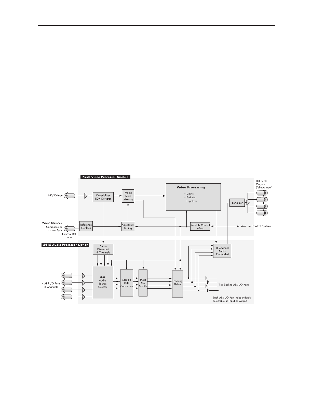
An 8415 Audio Processor submodule can be installed on the 7550 module. The 8415 is an
eight channel processor designed to provide superior handling of embedded audio. The disembedder on the input side follows the timing of the video input, even if that input is
asynchronous to the house reference. The embedder on the output side is synchronous to
house. This allows embedded audio to be safely bypassed around the video Framestore to
properly preserve re-synchronized embedded audio for correct lip sync. The Control
modules in the frame (5030 or 5035) must be running software version 2.0.5 or later for
proper operation of the 8415.
Every function and parameter on the 7550 and 8415 can be controlled from an Express
Panel, Avenue Touch Panel, or the Avenue PC Control Application. Memory registers can
be used to save the complete configuration of the module, making it easy to change
instantly between different configurations.
Ten 7550 Video Processors (including the 8415 Audio option) can be accommodated by the
Avenue 3 RU frame or four modules can be installed in the 1 RU frame.
Modules at software version 2.2.0 or later support SNMP (Simple Network Management
Protocol) monitoring. For each applicable signal processing module, module, signal, and
reference status are reported. For complete details on using SNMP monitoring, refer to
the Avenue System Overview in the manual that accompanies each frame.
7550 with 8415 Functional Block Diagram
Model 7550 HD Video Proc Frame Sync
7550-3
Page 4

Model 7550 HD Video Proc Frame Sync
APPLICATIONS
This section provides two typical applications for utilizing the full versatility of the 7550
Video Processor module and the optional 8415 submodule.
Timing of an Asynchronous Input
As shown in the illustration below, the 7550 module with an 8415 audio submodule can
accept an asynchronous video input such as the feed from a satellite receiver. The module
can time the signal to a house reference and send the timed output to a router for distribution throughout the facility. With the 8415 audio submodule installed, the audio lip
sync of the input signal is preserved.
Embedding AES Audio
In the example shown below, the 7550 module with an 8415 audio submodule is
embedding AES audio into the SDI output of a production switcher. The Proc Amp on the
7550 is used to make final adjustments to the video which is then output to a video server.
7550-4
7550 Module Timing an Asynchronous Satellite Input Signal
7550 Module Timing an Asynchronous Satellite Input Signal
Page 5
7550-5
INSTALLATION
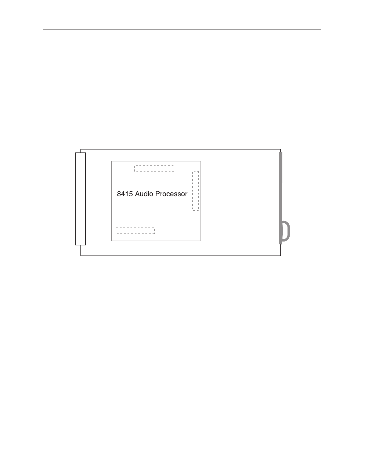
8415 Submodule Installation
The optional 8415 Series submodule installs on the component side of the 7550 Video
Processing module circuit board. If the option is ordered with the 7550 module, it will
come already installed.
To install the 8415 audio submodule, locate the three connectors on the left side of the
circuit board as shown below and line the connectors up, checking the alignment. Press
carefully into place to seat the submodule.
Note: Operation of the 8415 Audio submodule requires that the Control module
(5030/5035) in the frame be running version 2.0.5 software or later.
7550 Video Processing Module
Plug the 7550 module into any one of the slots in the 1 RU or 3 RU frame and install the
plastic overlay provided onto the corresponding group of rear BNC connectors associated
with the module location. Note that the plastic overlay has an optional adhesive backing
for securing it to the frame. Use of the adhesive backing is only necessary if you would
like the location to be permanent and is not recommended if you need to change module
locations. This module may be hot-swapped (inserted or removed) without powering down
or disturbing performance of the other modules in the system.
Model 7550 HD Video Proc Frame Sync
8415 Submodule Installation
Page 6
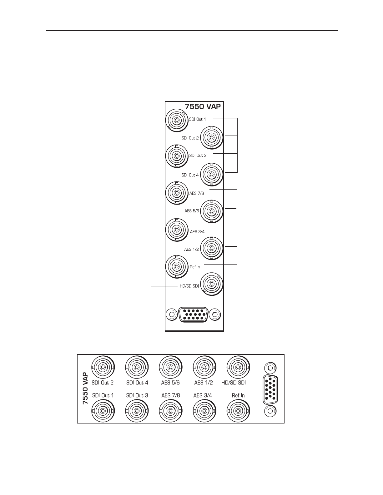
3 RU Backplane
1 RU Backplane
AES 1/2, 3/4, 5/6 and 7/8 –
Connect AES digital audio to
the AES 1/2 and AES 3/4
inputs.
SDI Out 1-4– Connect the
processed HD orSD video
outputs to the desired
destinations.
Model 7550 HD Video Proc Frame Sync
Ref In – Connect a composite
video input (PAL or NTSC) or
HD Tri-level sync signal as
required if you are using an
external reference.
HD/SD SDI – Connect an
HD SDI or SD SDI input
signal for processing.
CABLING
Refer to the 3 RU and 1 RU backplane diagrams of the module below for cabling instructions. Note that unless stated otherwise, the 1 RU cabling explanations are identical to
those given in the 3 RU diagram.
7550-6
Page 7

MODULE CONFIGURATION AND CONTROL
The configuration parameters for each Avenue module must be selected after installation.
This can be done remotely using one of the Avenue remote control options or locally using
the module front panel controls. Each module has a Remote/Local switch on the front
edge of the circuit board which must first be set to the desired control mode.
The configuration parameter choices for the module will differ between Remote and
Local modes. In Remote mode, the choices are made through software and allow more
selections. The 7550 Parameter Table later in this section summarizes and compares
the various configuration parameters that can be set remotely or locally and the
default/factory settings. It also provides the default User Levels for each control. These
levels can be changed using the Avenue PC application
If you are not using a remote control option, the module parameters must be configured
from the front panel switches. Parameters that have no front panel control will be set to a
default value. The Local switches are illustrated in the Front Panel Controls and
Indicators section following the 7550 Parameter Table. The Local switches are
inactive when the Remote/Local switch is in the Remote position.
In the Remote mode, Avenue module parameters can be configured and controlled from
one or both of the remote control options, the Avenue Touch Screen or the Avenue PC
Application. Once the module parameters have been set remotely, the information is
stored on the module CPU. This allows the module to be moved to a different cell in the
frame at your discretion without losing the stored information.
For setting the parameters remotely using the Avenue PC option, refer to the Avenue PC
Remote Configuration section of this document.
For setting the parameters remotely using the Avenue Touch Screen option, refer to the
Avenue Touch Screen Remote Configuration section of this document following
Avenue PC.
For setting the parameters remotely using the Avenue Express Control Panel option, refer
to the Avenue Express Control Panel data pack that comes with the panel option.
7550-7
Model 7550 HD Video Proc Frame Sync
Page 8

Configuration Summary
This section provides a general overview of the configuration for the 7550 module. The
controls available for configuration with remote control are summarized and tips and
examples are given for using particular controls to achieve the best results.
Video Processing
The 7550 has a full-featured Proc Amp for adjustment of every signal parameter. Proc
controls adjust the overall video signal. A Legalizer menu allows adjustment of black and
white clips to prevent excessive signal excursions or the output can be set to meet default
RGB values determined on a pixel by pixel basis.
The available video/color processing and video timing and output remote control menus
are summarized below:
• Proc: Video Gain, Chroma, Pedestal and Hue are standard Proc Amp controls
affecting the entire signal. The Hue control gives phase rotation of the color vectors
in the manner of an NTSC composite Proc Amp.
• Clip: The Clip menu provides enabling of a Legalizer which insures signal levels
will not exceed those permitted in the composite domain. Thus its use can insure a
television transmitter will not be presented illegal video input. If set to Off or set
for Legal RGB, adjustments are grayed out and may not be changed. When set to
Y, Cr, Cb, controls for black and white clipping and chroma limiting are provided.
• Timing: The 7550’s comprehensive range of timing allows complete flexibility in
placement of the output picture relative to the applied reference input. A Frame
Synchronizer can be enabled to allow timing the signal to an external house
reference. Frame Delay can be set for up to three frames of delay.
• Video Out: The Bypass selection takes the 7550 Proc Amp out of the video path by
routing the signal around it to the output. One of four internally generated test
signals may be selected to be sent to the output signal if needed. Embedded Audio
is removed from the SDI stream when Strip is selected in the Strip Audio window.
There are Wide, and Narrow vertical blanking choices. Wide gives blanking
through line 20 (NTSC) or line 22 (PAL), while narrow produces blanking through
line 9 (NTSC) or Line 6 (PAL) of both fields.
• Trims: Cb and Cr offsets allow black balance to be corrected while Cb and Cr
gains permit trimming of levels on these two axes. Y/C delay allows the operator to
correct inaccuracy of timing of color information relative to luminance. These trims
are functional regardless of the input or output formats in use.
• Memory: Up to five configurations of the 7550 may be saved into memory
registers for later recall. All parameters – gains, input format, filters, blanking,
etc. – and are saved in each memory. The 7550 can be used with the 8415
submodule for audio disembedding, channel swapping and re-embedding in a particular application. In another application other audio parameters can be adjusted
for a particular configuration. These two setups could be stored in memory
registers and one or the other recalled for instant restoration of the required configuration.
7550-8
Model 7550 HD Video Proc Frame Sync
Page 9

8415 Audio Processor Configuration
The 8415 Audio Processor accepts audio from the AES input connectors and can disembed
audio from the incoming HD or SD SDI video stream.
Between the input and output is a 8x8 mixer with tracking audio delay. Any incoming
audio can be mixed, level controlled and/or shuffled to another output channel by means
of the integrated audio router. The tracking audio delay allows synchronization and
timing to be maintained with time base corrected video passing through the video frame
synchronizer of the 7550.
A built in sample rate converter allows use of asynchronous AES input signals. The Audio
Processors also support encoded audio formats such as AC-3 and Dolby-E. Because these
data streams cannot tolerate sample rate conversion, they must be input to the Audio
Processors synchronous to the video. All audio processing is performed at the full 24 bit
resolution of the system. At the output side of the submodule the eight audio channels
may be simultaneously routed to AES output connectors while also being embedded on the
outgoing SDI video. An adapter is also available to allow the AES I/O to be converted from
BNC to 110 ohm balanced on the output.
The available audio processing remote control menus are summarized below:
• Audio Mix: This menu gives full access to the 8x8 audio mixer controls. Any input
channel can be routed to any or all output busses. Sliders in Avenue PC or rotary
knobs on a control panel permit levels to be adjusted from -70dB to +12dB.
Alternatively a value can be put in the numeric window, followed by the Enter key,
and this will become the new gain setting. Default buttons are provided for return
to zero level.
The Tie function is used for stereo operation where gain of a pair of channels is
usually desired to be the same. An invert selection allows inversion of a channel to
permit phase correction.
• Audio In: Status indicators show presence of AES and embedded (HD SDI or
SD SDI) audio inputs. The Audio In A and Audio In B menus allow selection of
inputs to the audio mixer. The choices for the 8415 are AES 1/2, AES 3/4, AES 5/6
and AES 7/8 and SDI 1/2, SDI 3/4, SDI 5/6, and SDI 7/8. Thus any pair of input
audio signals can be routed to either pair of input buses of the output audio mixer.
• Audio Mode: The Audio Mode control is provided to allow an SDI input with
embedded audio to operate in Audio (normal) or Data (non-audio). The 7550 can
handle both types of content present in AC-3 or Dolby E signals. Some synchronizing requirements are necessary for supporting these protocols.
Select the Audio mode when the input audio signal is a standard audio signal
carrying two channels of linear audio. No special timing requirements are needed
in this mode.
Use the Data mode when the serial digital audio is a non-audio, or data, signal.
Some special synchronizing requirements must be observed in this mode as
described in the following examples.
HD or SD SDI Signal with embedded data – For this case, if an SDI
signal with embedded data is applied to the input, the content will be
handled by passing through the 7550 frame store memory to the output of
the 7550. No audio submodule is required. The audio input signal in this
7550-9
Model 7550 HD Video Proc Frame Sync
Page 10

case is synchronous to the timing reference. This is normal operation of the
7550 and no special configuration is necessary.
Data mode signal to be disembedded and output as an AES stream –
This mode requires the use of an audio submodule to disembed the
de-serialized SDI input and route the channels to the correct path. If one
of the channels is normal audio, it can be mixed, swapped, shuffled, and
delayed by the audio submodule. If the other channel is non-audio data, it
bypasses the normal audio functions and is carried to the AES output
formatter and driver.
When in the Data mode, the AES formatter is driven by the output timing
of the 7550, the original SDI input must be synchronous to the reference
input or the 7550 must be configured to use the SDI signal as the timing
reference.
Data mode signal to be disembedded, output as AES, then reembedded – In this case the audio submodule is also required. This case is
similar to the one above, while the disembedded data is re-embedded in the
SDI output of the 7550. The same timing requirements apply.
Original embedded data to be left unchanged with an additional
embedded group to be added – The original embedding in the SDI input
passes through the 7550 processing path. At the same time, an audio
submodule is used to create a second embedded group which is placed in
cascade, following the original audio group which contains the data mode
signal.
A data mode signal in AES format is input to the audio submodule –
This example could be used when there is a need to embed the AES data
into the output of the 7550. In this case the AES data input must be synchronous. When being used in this manner, the audio submodule can embed
data mode AES into one pair of channels in an embedded group, while
embedding conventional audio into the other pair.
• Audio Delay: With the Auto Track switched On, audio will be delayed the same
amount as the video passing through the 7550 frame synchronizer thus preserving
lip sync. If incoming audio is early due to signals passing through an upstream
frame sync without a compensating audio delay, Bulk Delay can be used to correct
the problem. Up to 1000 mS of fixed delay can be added to compensate for
upstream timing errors.
7550-10
Model 7550 HD Video Proc Frame Sync
Page 11

Model 7550 HD Video Proc Frame Sync
CONTROL LOCAL REMOTE DEFAULT USER LEVEL
VIDEO AND COLOR PROCESSING
Ref Source
Ext Ref
Master Ref
Video In Ref
Ext Ref Admin
Proc Amp Gain 100% 0 to 150% 100% Admin
Proc Amp Chroma 100% 0 to 150% 100% Admin
Proc Amp Pedestal 0 IRE +/– 30 IRE 0 IRE Admin
Proc Amp Hue 0 degrees +/– 180 degrees 0 degrees Admin
Legalizer
Switch 2
Legalizer:
On or Off
Off
Y–Cr–Cb
Legal RGB
Off Admin
B/W Clip Off
Off
On
Off Admin
Black Clip – 8 IRE – 8 to 6.2 IRE – 8 IRE Admin
White Clip 110 IRE 95 to 110 IRE 110 IRE Admin
Chroma Limit 85% 85 to 125% 85% Admin
Frame Sync
Switch 1
Frame Sync:
On or Off
(Ext Ref only)
Off
On
On Admin
Frame Delay 0 frames 0 to 3 frames 0 frames Admin
Timing 0 lines +/– 1200 lines 0 lines Admin
7550-11
7550 Parameter Table
Page 12

Model 7550 HD Video Proc Frame Sync
7550-12
CONTROL LOCAL REMOTE DEFAULT USER LEVEL
VIDEO OUTPUT CONTROLS
Bypass Normal
Normal
Bypass
Normal Admin
Strip Audio Off
Off
On
Off Admin
Test Pattern Off
Off
Bars
Black
Pathological
Unit Circle
Off Admin
Signal Mute No Muting
No Muting
Mutes on Noise
Freeze on Noise
No Muting Level 1
BLANKING and TRIM CONTROLS
Vert Blanking Wide
Wide
(PAL Lines 1-22<
NTSC Lines 1-20)
Narrow
(PAL Lines 1-6<
NTSC Lines 1-9)
Wide Admin
Cb Offset 0 IRE +/– 100 IRE 0 IRE Admin
Cr Offset 0 IRE +/– 100 IRE 0 IRE Admin
Cb Gain 0 IRE +/– 20 IRE 0 IRE Admin
Cr Gain 0 IRE +/– 20 IRE 0 IRE Admin
7550 Parameter Table (Continued)
Page 13

CONTROL LOCAL REMOTE DEFAULT USER LEVEL
AUDIO CONTROLS (8415 Audio Submodule Installed)
Input Level
Ch 1 – Ch 8
0 dB -70 to +12 dB 0 dB Level 1
Ch 1-8 Output Bus
Ch 1 – Output 1
Ch 2 – Output 2
Ch 3 – Output 3
Ch 4 – Output 4
Ch 5 – Output 5
Ch 6 – Output 6
Ch 7 – Output 7
Ch 8 – Output 8
Output Bus 1 – 8
Ch 1 – Output 1
Ch 2 – Output 2
Ch 3 – Output 3
Ch 4 – Output 4
Ch 5 – Output 5
Ch 6 – Output 6
Ch 7 – Output 7
Ch 8 – Output 8
Tie
Level 1
1/2 Input
3/4 Input
5/6 Input
7/8 Input
Switch 8:
AES or Embed
AES 1/2
AES 3/4
AES 5/6
AES 7/8
SDI 1/2
SDI 3/4
SDI 5/6
SDI 7/8
AES 1/2 Level 1
1/2, 3/4, 5/6, 7/8
Mode
Auto
Audio
Data
Auto
Auto Level 1
Demux Group Group 1
Group 1
Group 2
Group 3
Group 4
Group 1 Level 1
Auto Track On
Off
On
On Level 1
Bulk Delay 0 msec 0 – 1000 msec 0 msec Level 1
Audio Embed Replace
Off
Replace
Cascade
Replace Level 1
Mux Group A and B Group 1
Group 1
Group 2
Group 3
Group 4
Group 1 Level 1
Dig Ref Level –20 dBFS
–20 dBFS
–18 dBFS
–20 dBFS Level 1
7550 Parameter Table (Continued)
Model 7550 HD Video Proc Frame Sync
7550-13
Page 14

Front Panel Controls and Indicators
Each front edge indicator and switch setting is shown in the diagram below:
Remote/Local switch:
Set to the mode you
will be using.
Pwr green LED:
Indicates the presence (ON) or
absence (OFF) of power (+5V).
Run green LED:
OFF:
A power fault or halted CPU
ON:
A halted CPU
FAST BLINK:
CPU Run error
SLOW BLINK:
System OK. (If SPI control
is active from the main
frame System Control
Module, all Run indicators
will be synchronized.)
HD/SD In green LED:
On indicates input video signal
is present and detected.
OFF no input video signal
detected on the input.
Ref green LED:
On when the selected reference
source is detected.
OFF when no reference signal is
detected.
Frame Sync switch:
Turn Frame Sync On or Off when
using an external reference.
Legalizer
switch:
Turn On to enable legalizer or OFF
to disable.
AES/Embed
switch:
Select AES or Embed to identify
what type of digital audio is being
input to the module.
EDH Err red LED:
On when EDH is present and
CRC errors are detected.
OFF when EDH is not present or
CRC errors are not detected.
AES In 1/2
green LED:
On when an AES input is
detected on the AES 1/2
audio input.
OFF when no audio is
detected on AES 1/2.
Embed
green LED:
On when an audio ancillary packet
is detected in the serial stream.
OFF when no audio ancillary
packet is detected.
AES 3/4 green LED:
On when an AES input is
detected on the AES 3/4
audio input.
OFF when no AES audio is
detected on AES 3/4.
Model 7550 HD Video Frame Sync
7550-14
AES 5/6 green LED:
On when an AES input is
detected on the AES 5/6
audio input.
OFF when no AES audio is
detected on AES 5/6.
AES 7/8
green LED:
On when an AES input is
detected on the AES 7/8
audio input.
OFF when no AES audio is
detected on AES 7/8.
Page 15

Avenue PC Remote Configuration
The Avenue PC remote control menus for this module are illustrated and explained below.
Refer to the 7550 Parameter Table for a summary of available parameters that can be
set remotely through the menus illustrated. The Configuration Summary gives tips
and general background information on setting the parameters. For more information on
using Avenue PC, refer to the Avenue PC Control Application Software data pack.
Parameter fields that are grayed out can indicate one of the following conditions:
• An option is not installed.
• The function is not active.
• The module is locked.
• The User Level set with Avenue PC is not accessible from the current User Level.
7550 Avenue PC Menus
The Vid In menu shown below allows you to configure the following input sources:
• Ref Source – use this control to set the reference input source.
Status reporting is provided for the following conditions:
• Input – reports the input status as No Input, 720p/50, 720p/59.94, 720p/60,
1080i/50, 1080i/59.94, 1080i/60, 1080p/25, 1080p/23.98, 1080p/24, 1080sF/25,
1080sF/24, 1080sF/23.98, SD 625, SD 525,orUnknown Std.
• Input Error – reports one of the following errors: No Error, No Input Lock,
EDH/CRC Error, and TRS Error.
• Error Seconds – displays the number of seconds that a detected EDH error has
been present in the serial data stream.
• Reference – reports the status of the reference input as either No Reference,
Ref Mismatch, Ref Unlocked, Ref 525 Lock, Ref 625 Lock, or TLS Lock.
7550-15
Model 7550 HD Video Proc Frame Sync
Page 16

Model 7550 HD Video Frame Sync
The Proc menu shown below allows you to adjust the following video processing parameters for the signal:
• Gain – adjust the percentage of overall gain (luminance and chrominance).
• Chroma – adjust the percentage of chroma amplitude.
• Pedestal – adjust the pedestal (black) level of the signal in IRE.
• Hue – adjust the hue of the signal ± 180 degrees.
7550-16
Page 17

Use the Clip menu shown below to enable or disable the Legalizer circuitry on the
module which allows adjustment of the following parameters:
• Off – for no Legalizer.
• Y–Cr–Cb – selecting this choice will enable the Black and White Clip, and
Chroma Limiting controls.
• Black Clip – set the threshold for the black clip level. (No content will be
allowed below the level set.)
• White Clip – set the threshold for the white clip. (No content will be
allowed above the level set.)
• Chroma Limit – adjust the percentage of chroma limiting desired for the
output.
• Legal RGB – selecting this choice will set the module to default legal RGB parameters set on a pixel by pixel basis and will gray out the clip and chroma limit
controls.
7550-17
Model 7550 HD Video Proc Frame Sync
Page 18

When an 8415 Audio Processor submodule is installed, use the Aud Mix A and B menus
shown to control the audio input levels and mixing and shuffling of the audio inputs to
output. Each output bus assignment will be indicated by a green box.
For Channels 1 –4, use the Audio Mix A menu to set the following
• Input Ch 1 – assign Input Channel 1 to the desired output bus or tie to
Channel 2. Set the input level using the slider control or by entering a number in
the window and pressing the Enter key on your PC.
• Input Ch 2 – assign Input Channel 2 to the desired output bus or tie to
Channel 1. Set the input level using the slider control or by entering a number in
the window and pressing the Enter key on your PC.
• Input Ch 3 – assign Input Channel 3 to the desired output bus or tie to
Channel 4. Set the input level using the slider control or by entering a number in
the window and pressing the Enter key on your PC..
• Input Ch 4 – assign Input Channel 4 to the desired output bus or tie to
Channel 3. Set the input level using the slider control or by entering a number in
the window and pressing the Enter key on your PC..
Selecting the Tie button in Input Ch 1 or Input Ch 2 will tie the two controls together.
Selecting the Tie button in Input Ch 3 or Input Ch 4 will tie the controls for these
channels together.
Select the Default button to return to the default value.
Select the Invert button to invert the phase of the audio content.
Model 7550 HD Video Frame Sync
7550-18
Page 19

For Channels 5 –8, use the Audio Mix B menu shown below to set the following
• Input Ch 5 – assign Input Channel 5 to the desired output bus or tie to
Channel 6. Set the input level using the slider control or by entering a number in
the window and pressing the Enter key on your PC.
• Input Ch 6 – assign Input Channel 6 to the desired output bus or tie to
Channel 5. Set the input level using the slider control or by entering a number in
the window and pressing the Enter key on your PC.
• Input Ch 7 – assign Input Channel 7 to the desired output bus or tie to
Channel 8. Set the input level using the slider control or by entering a number in
the window and pressing the Enter key on your PC..
• Input Ch 8 – assign Input Channel 8 to the desired output bus or tie to
Channel 7. Set the input level using the slider control or by entering a number in
the window and pressing the Enter key on your PC..
Selecting the Tie button in Input Ch 5 or Input Ch 6 will tie the two controls together.
Selecting the Tie button in Input Ch 7 or Input Ch 8 will tie the controls for these
channels together.
Select the Default button to return to the default value.
Select the Invert button to invert the phase of the audio content.
7550-19
Model 7550 HD Video Frame Sync
Page 20

Use the Aud In A menu shown below for the 8415 to adjust the following parameters:
• 1/2 Input – select the input audio source for Input 1/2.
• 3/4 Input – select the input audio source for Input 3/4.
When an AES input pair is selected as an input, the corresponding AES BNC on
the rear of the module will become an input. If an AES input is not selected, the
corresponding BNC on the rear of the module will automatically become an output.
Refer to the block diagram on page 3 for an illustration of the input/output BNCs.
• 1/2 Mode – for a Serial input with embedded audio, select the type of audio in the
stream:
• Audio – the embedded stream is standard audio.
• Data – the embedded stream is a non-audio signal.
• Auto – the module will detect the type of signal embedded in the stream,
audio or data.
• 3/4 Mode – select the type of audio in the serial stream as described above.
• Demux Group – select the embedded audio group to demultiplex from the selections. The status of embedded audio is shown in the Embed In A view. It will be
reported as None or Present.
The status of the corresponding audio inputs are shown next to the control. Status is
reported as one of the following:
• No Input – no serial digital embedded audio is detected.
• Audio Sync – the audio embedded in the stream is synchronous with the timing
reference.
• Data Sync – the data embedded in the stream is synchronous with the timing
reference.
• Audio Async – the audio embedded in the stream is non-synchronous with the
timing reference.
Model 7550 HD Video Frame Sync
7550-20
Page 21

Use the Aud In B menu shown below for the 8415 to adjust the following parameters:
• 5/6 Input – select the input audio source for Input 5/6.
• 7/8 Input – select the input audio source for Input 7/8.
When an AES input pair is selected as an input, the corresponding AES BNC on
the rear of the module will become an input. If an AES input is not selected, the
corresponding BNC on the rear of the module will automatically become an output.
Refer to the block diagram on page 4 for an illustration of the input/output BNCs.
• 5/6 Mode – for a Serial input with embedded audio, select the type of audio in the
stream:
• Audio – the embedded stream is standard audio.
• Data – the embedded stream is a non-audio signal.
• Auto – the module will detect the type of signal embedded in the stream,
audio or data.
• 7/8 Mode – select the type of audio in the serial stream as described above.
• Demux Group – select the embedded audio group to demultiplex from the selections. The status of embedded audio is shown in the Embed In B view. It will be
reported as None or Present.
The status of the corresponding audio inputs are shown next to the control. Status is
reported as one of the following:
• No Input – no serial digital embedded audio is detected.
• Audio Sync – the audio embedded in the stream is synchronous with the timing
reference.
• Data Sync – the data embedded in the stream is synchronous with the timing
reference.
• Audio Async – the audio embedded in the stream is non-synchronous with the
timing reference.
7550-21
Model 7550 HD Video Frame Sync
Page 22

Use the Aud Delay menu shown below to adjust the amount of audio delay on the
output:
• Auto Track – enable auto tracking by selecting On or Off.
• Bulk Delay – set the amount of bulk delay using the left and right arrows or
enter a value in the msec field and press the Enter key on your PC.
The amount of total delay will be reported in msec in the Total Delay window.
Use the Aud Out menu shown below to adjust the following audio output parameters:
• Audio Embed A – turn embedding Off for no embedding to take place in the
output signal. Select Replace to replace the targeted group in the stream with
new content. If there is no such group already present, the new content will be
placed in the horizontal interval in normal cascade, following any other content
already there. When Cascade is selected, the audio channels are placed after any
existing content. Replace All will strip all of the original content and the new
content is placed at the beginning of the horizontal interval.
• Audio Embed B – identical to Audio Embed A but no Replace All function is
required as this will occur upstream in the A embedder.
• Mux Group A – select the multiplexed group to be embedded in embedder A in
the output.
• Mux Group B – select the multiplexed group to be embedded in embedder B in
the output.
• Dig Ref Level – set the digital reference level for the audio output.
Model 7550 HD Video Frame Sync
7550-22
Page 23

Use the Timing menu shown below to adjust the following parameters:
• Frame Sync – turn the Frame Sync function on or off.
• Timing – when Frame Sync is on, adjust the horizontal timing of the output signal
to place the leading edge of sync coincident with other sources.
• Frame Delay – for asynchronous inputs, set the amount of frame delay desired.
This menu provides a Delay window at the bottom of the screen that will report the total
delay in lines of the module.
Model 7550 HD Video Frame Sync
7550-23
Page 24

Use the Vid Out menu shown below to adjust the following parameters:
• Bypass – set to Normal or Bypass to completely bypass any digital processing.
• Vert Blanking – set the vertical blanking for Wide or Narrow.
• Test Pattern – select a test pattern to be sent to the video output of the module.
• Signal Mute – set to either mute the output to black when noise is present, to
freeze to the last frame, or select no muting.
• Strip Audio – select the box to strip embedded audio from the output. Leave the
box unselected to pass embedded audio through to the output.
The Memory menu shown below allows you to save overall module setups to five memory
registers as follows:
• Select Save, then one of the five memory registers Reg 1 – 5. The box will turn
green. The entire module setup is now saved in the selected register.
• To recall a register, select the register box. If there is information saved, the box
will turn green. The saved setup will now be loaded to the module. Up to five
different module setups can be saved and recalled using the individual registers.
Model 7550 HD Video Frame Sync
7550-24
Page 25

The Trim menu allows you to correct subtle issues in the individual color difference
channels with offset and gain controls. The offset controls adjust the DC offsets above or
below the nominal points. This can be used to correct black balance errors. The gain
controls adjust the amplitude of each channel.
Use the controls described below to make the offset and gain corrections:
• Cb Offset – adjust the DC offset of the Cb channel to between ± 100 IRE.
• Cr Offset – adjust the DC offset of the Cr channel to between ± 100 IRE.
• Cb Gain – adjust the amplitude of the Cb channel to between ± 20 IRE.
• Cr Gain – adjust the amplitude of the Cr channel to between ± 20 IRE.
Model 7550 HD Video Frame Sync
7550-25
Page 26

Avenue Touch Screen Remote Configuration
The Avenue Touch Screen remote control status menu for this module is illustrated and
explained below. Refer to the 7550 Parameter Table for a summary of available parameters that can be set remotely through the menus illustrated. The Configuration
Summary gives tips and general background information on setting the parameters. For
more information on using Avenue Touch Screen, refer to the Avenue System Overview.
Parameter fields that are grayed out can indicate one of the following conditions:
• An option is not installed.
• The function is not active.
• The module is locked.
• The User Level set with Avenue PC is not accessible from the current User Level.
7550 Avenue Touch Screen Menus
The Vid In menu shown below allows you to configure the following input sources:
• Ref Source – use this control to set the reference input source.
Status reporting is provided for the following conditions:
• Input – reports the input status as No Input, 720p/50, 720p/59.94, 720p/60,
1080i/50, 1080i/59.94, 1080i/60, 1080p/25, 1080p/23.98, 1080p/24, 1080sF/25,
1080sF/24, 1080sF/23.98, SD 625, SD 525,orUnknown Std.
• Input Error – reports one of the following errors: No Error, No Input Lock,
EDH/CRC Error, and TRS Error.
• Error Seconds – displays the number of seconds that a detected EDH error has
been present in the serial data stream.
• Reference – reports the status of the reference input as either No Reference,
Ref Mismatch, Ref Unlocked, Ref 525 Lock, Ref 625 Lock, or TLS Lock.
7550-26
Model 7550 HD Video Frame Sync
Page 27

The Proc menu shown below allows you to adjust the following video processing parameters for the signal:
• Gain – adjust the percentage of overall gain (luminance and chrominance).
• Chroma – adjust the percentage of chroma amplitude.
• Pedestal – adjust the pedestal (black) level of the signal in IRE.
• Hue – adjust the hue of the signal ± 180 degrees.
Model 7550 HD Video Frame Sync
7550-27
Page 28

7550-28
Model 7550 HD Video Frame Sync
Use the Clip menu shown below to enable or disable the Legalizer circuitry on the
module which allows adjustment the following parameters:
• Off – for no Legalizer.
• Y–Cr–Cb – selecting this choice will enable the Black and White Clip, and
Chroma Limiting controls at the right of the menu.
• Black Clip – set the threshold for the black clip level. (No content will be
allowed below the level set.)
• White Clip – set the threshold for the white clip. (No content will be
allowed above the level set.)
• Chroma Limit – adjust the percentage of chroma limiting desired for the
output.
• Legal RGB –selecting this choice will set the module to default legal RGB parameters set on a pixel by pixel basis and will gray out the clip and chroma limit
controls.
Page 29

When an 8415 Audio Processor submodule is installed, use the Aud Mix A and B menus
shown to control the audio input levels and mixing and shuffling of the audio inputs to
output. Each output bus assignment will be indicated by a green box.
For Channels 1 –4, use the Audio Mix A menu to set the following
• Input Ch 1 – assign Input Channel 1 to the desired output bus or tie to
Channel 2. Set the input level using the slider control or by entering a number in
the pop-up window and pressing the Enter key.
• Input Ch 2 – assign Input Channel 2 to the desired output bus or tie to
Channel 1. Set the input level using the slider control or by entering a number in
the pop-up window and pressing the Enter key.
• Input Ch 3 – assign Input Channel 3 to the desired output bus or tie to
Channel 4. Set the input level using the slider control or by entering a number in
the pop-up window and pressing the Enter key.
• Input Ch 4 – assign Input Channel 4 to the desired output bus or tie to
Channel 3. Set the input level using the slider control or by entering a number in
the pop-up window and pressing the Enter key.
Selecting the Tie button in Input Ch 1 or Input Ch 2 will tie the two controls together.
Selecting the Tie button in Input Ch 3 or Input Ch 4 will tie the controls for these
channels together.
Select the Default button to return to the default value.
Select the Ø button to invert the phase of the audio content. reference.
Model 7550 HD Video Frame Sync
7550-29
Page 30

7550-30
Model 7550 HD Video Frame Sync
For Channels 5 –8, use the Audio Mix B menu shown below to set the following
• Input Ch 5 – assign Input Channel 5 to the desired output bus or tie to
Channel 6. Set the input level using the slider control or by entering a number in
the pop-up window and pressing the Enter key.
• Input Ch 6 – assign Input Channel 6 to the desired output bus or tie to
Channel 5. Set the input level using the slider control or by entering a number in
the pop-up window and pressing the Enter key.
• Input Ch 7 – assign Input Channel 7 to the desired output bus or tie to
Channel 8. Set the input level using the slider control or by entering a number in
the pop-up window and pressing the Enter key.
• Input Ch 8 – assign Input Channel 8 to the desired output bus or tie to
Channel 7. Set the input level using the slider control or by entering a number in
the pop-up window and pressing the Enter key.
Selecting the Tie button in Input Ch 5 or Input Ch 6 will tie the two controls together.
Selecting the Tie button in Input Ch 7 or Input Ch 8 will tie the controls for these
channels together.
Select the Default button to return to the default value.
Select the Ø button to invert the phase of the audio content.
Page 31

Use the Aud In A menu shown below for the 8415 to adjust the following parameters:
• 1/2 Input – select the input audio source for Input 1/2.
• 3/4 Input – select the input audio source for Input 3/4.
When an AES input pair is selected as an input, the corresponding AES BNC on
the rear of the module will become an input. If an AES input is not selected, the
corresponding BNC on the rear of the module will automatically become an output.
Refer to the block diagram on page 3 for an illustration of the input/output BNCs.
• 1/2 Mode – for a Serial input with embedded audio, select the type of audio in the
stream:
• Audio – the embedded stream is standard audio.
• Data – the embedded stream is a non-audio signal.
• Auto – the module will detect the type of signal embedded in the stream,
audio or data.
• 3/4 Mode – select the type of audio in the serial stream as described above.
• Demux Group – select the embedded audio group to demultiplex from the selections. The status of embedded audio is shown in the Embed In A view. It will be
reported as None or Present.
The status of the corresponding audio inputs are shown next to the control. Status is
reported as one of the following:
• No Input – no serial digital embedded audio is detected.
• Audio Sync – the audio embedded in the stream is synchronous with the timing
reference.
• Data Sync – the data embedded in the stream is synchronous with the timing
reference.
• Audio Async – the audio embedded in the stream is non-synchronous with the
timing reference.
Model 7550 HD Video Frame Sync
7550-31
Page 32

Use the Aud In B menu shown below for the 8415 to adjust the following parameters:
• 5/6 Input – select the input audio source for Input 5/6.
• 7/8 Input – select the input audio source for Input 7/8.
When an AES input pair is selected as an input, the corresponding AES BNC on
the rear of the module will become an input. If an AES input is not selected, the
corresponding BNC on the rear of the module will automatically become an output.
Refer to the block diagram on page 4 for an illustration of the input/output BNCs.
• 5/6 Mode – for a Serial input with embedded audio, select the type of audio in the
stream:
• Audio – the embedded stream is standard audio.
• Data – the embedded stream is a non-audio signal.
• Auto – the module will detect the type of signal embedded in the stream,
audio or data.
• 7/8 Mode – select the type of audio in the serial stream as described above.
• Demux Group – select the embedded audio group to demultiplex from the selections. The status of embedded audio is shown in the Embed In B view. It will be
reported as None or Present.
The status of the corresponding audio inputs are shown next to the control. Status is
reported as one of the following:
• No Input – no serial digital embedded audio is detected.
• Audio Sync – the audio embedded in the stream is synchronous with the timing
reference.
• Data Sync – the data embedded in the stream is synchronous with the timing
reference.
• Audio Async – the audio embedded in the stream is non-synchronous with the
timing reference.
7550-32
Model 7550 HD Video Frame Sync
Page 33

Use the Aud Delay menu shown below to adjust the amount of audio delay on the
output:
• Auto Track – enable auto tracking by selecting On or Off.
• Bulk Delay – set the amount of bulk delay using the left and right arrows or
enter a value in the msec pop-up window and press the Enter key.
The amount of total delay will be reported in msec in the Total Delay window.
Model 7550 HD Video Frame Sync
7550-33
Page 34

Use the Aud Out menu shown below to adjust the following audio output parameters:
• Audio Embed A – turn embedding Off for no embedding to take place in the
output signal. Select Replace to replace the targeted group in the stream with
new content. If there is no such group already present, the new content will be
placed in the horizontal interval in normal cascade, following any other content
already there. When Cascade is selected, the audio channels are placed after any
existing content. Replace All will strip all of the original content and the new
content is placed at the beginning of the horizontal interval.
• Audio Embed B – identical to Audio Embed A but no Replace All function is
required as this will occur upstream in the A embedder.
• Mux Group A – select the multiplexed group to be embedded in embedder A in
the output.
• Mux Group B – select the multiplexed group to be embedded in embedder B in
the output.
• Dig Ref Level – set the digital reference level for the audio output.
Model 7550 HD Video Frame Sync
7550-34
Page 35

Use the Timing menu shown below to adjust the following parameters:
• Frame Sync – turn the Frame Sync function on or off.
• Timing – when Frame Sync is on, adjust the horizontal timing of the output signal
to place the leading edge of sync coincident with other sources.
• Frame Delay – for asynchronous inputs, set the amount of frame delay desired.
This menu provides a Delay window at the bottom of the screen that will report the total
delay in lines of the module.
Model 7550 HD Video Frame Sync
7550-35
Page 36

Use the Vid Out menu shown below to adjust the following parameters:
• Bypass – set to Normal or Bypass to completely bypass any digital processing.
• Vert Blanking – set the vertical blanking for Wide or Narrow.
• Test Pattern – select a test pattern to be sent to the video output of the module.
• Signal Mute – set to either mute the output to black when noise is present, to
freeze to the last frame, or select no muting.
• Strip Audio – select the box to strip embedded audio from the output. Leave the
box unselected to pass embedded audio through to the output.
Model 7550 HD Video Frame Sync
7550-36
Page 37

The Memory menu shown below allows you to save overall module setups into up to five
memory registers as follows:
• Select Save, then one of the five memory registers Reg 1 – 5. The box will turn
green. The entire module setup is now saved in the selected register.
• To recall a register, select the register box. If there is information saved, the box
will turn green. The saved setup will now be loaded to the module. Up to five
different module setups can be saved and recalled using the individual registers.
Model 7550 HD Video Frame Sync
7550-37
Page 38

The Trim menu allows you to correct subtle issues in the individual color difference
channels with offset and gain controls. The offset controls adjust the DC offsets above or
below the nominal points. This can be used to correct black balance errors. The gain
controls adjust the amplitude of each channel.
Use the controls described below to make the offset and gain corrections:
• Cb Offset – adjust the DC offset of the Cb channel to between ± 100 IRE.
• Cr Offset – adjust the DC offset of the Cr channel to between ± 100 IRE.
• Cb Gain – adjust the amplitude of the Cb channel to between ± 20 IRE.
• Cr Gain – adjust the amplitude of the Cr channel to between ± 20 IRE.
7550-38
Model 7550 HD Video Frame Sync
Page 39

TROUBLESHOOTING
As a troubleshooting aid, the reference signal status and presence, power and CPU status
can be easily monitored from the front panel of this module using the front panel indicators.
Refer to the overall troubleshooting tips given below for the module:
Can’t control module:
• Check status of CPU Run green LED. Should be blinking slowly and in
unison with other modules if System module is present. If not, try removing
it and plugging it in again to be sure it is seated properly.
• System module may not be working properly if installed.
Module controls are grayed out:
• Module is locked or access to module controls is restricted by User Level.
• Local/Remote switch on module is in the Local position.
No signals out of module:
• Check status of Active LEDs. HD/SD In should be lit. If not, check the
input for presence and quality.
• Check cabling to inputs of module.
• Check inputs to destinations are terminated properly.
You may also refer to the technical support section of the Ensemble Designs web site for
the latest information on your equipment at the URL below:
http://www
.ensembledesigns.com/support
SOFTWARE UPDATING
Software upgrades for each module can be downloaded remotely if the optional System
Control module is installed. These can be downloaded onto your PC and then Avenue PC
will distribute the update to the individual module. (Refer to the Avenue PC documentation for more information). Periodically updates will be posted on our web site. If you do
not have the required System Control Module and Avenue PC, modules can be sent back
to the factory for software upgrades.
Model 7550 HD Video Frame Sync
7550-39
Page 40

Model 7550 HD Video Frame Sync
7550-40
WARRANTY AND FACTORY SERVICE
Warranty
This module is covered by a five year limited warranty, as stated in the main Preface of
this manual. If you require service (under warranty or not), please contact Ensemble
Designs and ask for customer service before you return the unit. This will allow the
service technician to provide any other suggestions for identifying the problem and
recommend possible solutions.
Factory Service
If you return equipment for repair, please get a Return Material Authorization Number
(RMA) from the factory first.
Ship the product and a written description of the problem to:
Ensemble Designs, Inc.
Attention: Customer Service RMA #####
870 Gold Flat Rd.
Nevada City, CA. 95959 USA
(530) 478-1830
Fax: (530) 478-1832
service@ensembledesigns.com
http://www.ensembledesigns.com
Be sure to put your RMA number on the outside of the box.
Page 41

SPECIFICATIONS
7550 HD Video Processor Frame Sync
Input
Number One
Type HD Serial Digital 1.485 Gb/s
SMPTE 274M,292M or 296M or
SD Serial Digital 270 Mb/s
SMPTE 259M
Impedance 75 ohm
Return Loss >15dB DC to 1.5GHz
HD Standards Supported
1080i (SMPTE 274M -4,5,6) 50, 59.94 or 60 Hz
720p (SMPTE 296M -1,2,3) 50, 59.94 or 60 Hz
1080p (SMPTE 274M -9,10,11) 23.98, 24, 25 Hz
1080sF (RP211 -14,15,16) 23.98, 24, 25Hz
Output
Number Four
Signal Type HD or SD Serial Digital,
follows input
Impedance 75 ohm
Return Loss >15 dB DC to 1.5 GHz
Reference Input
Number One external (module’s BNC)
One internal (frame master ref-BNC)
Signal Type PAL or NTSC composite video or HD Tri-Level Sync
Return Loss >40dB (applies to external ref input)
General Specifications
Power Consumption 10 watts (with audio option installed)
Temperature 0 to 40° C ambient (all specs met)
Relative Humidity 0 to 95%, non-condensing
Size Standard Avenue Module
Occupies one slot in 3RU or 1RU Frame
(including the 8415 Audio Processor
7550-41
Model 7550 HD Video Frame Sync
Page 42

8415 Audio Processor
AES/EBU Digital Inputs
Number 4 (Total of eight channels)
Type AES3id
Connectorization Coaxial, 75 Ω BNC
Bit Depth 20 or 24 Bit
Sample Rate 30KHz to 100KHz
(Sample Rate Converted internally to 48KHz)
Reference Level -18 or -20 dBFS (Selectable)
AC-3, Dolby-E Supported when inputs are synchronous
Embedded Inputs
Number 4 (from SDI video input)
8 channels from any 2 of 4 groups
Selectable to any of 4 groups
Type SMPTE 274M Compliant
Selectable to any of four groups
Channels Four
Bit Depth 20 or 24 Bit
AES/EBU Digital Outputs
Number 4 (Total of eight channels)
Type AES3id
Connectorization Coaxial, 75 Ω BNC
Bit Depth 20 or 24 Bit
Sample Rate 48 KHz
Synchronous to Video output
Reference Level -18 or -20 dBFS (Selectable)
Embedded Output
Number 4 or 2, depending on configuration
Type SMPTE 274M Compliant
Group Assign Cascade, or Replace any of 2 of four groups
Bit Depth 20 or 24 Bit
Model 7550 HD Video Frame Sync
7550-42
 Loading...