

Page 1

This data pack provides detailed installation, configuration and operation information for
the 7405 HD Test Signal Generator as part of the Avenue Signal Integration System.
The module information in this data pack is organized into the following sections:
• Module Overview
• Applications
• Installation
• Cabling
• Module Configuration and Control
°
Front Panel Controls and Indicators
°
Avenue PC Remote Control
°
Avenue Touch Screen Remote Control
• Troubleshooting
• Software Updating
• Warranty and Factory Service
• Specifications
7405-1
Model 7405
High Definition
Test Signal
Generator
Data Pack
ENSEMBLE
DESIGNS
Revision 1.1 SW v1.1.0
Page 2

MODULE OVERVIEW
The 7405 module is a high definition test signal generator that provides four identical HD
serial outputs and two identical black outputs, all synchronous to one another. In remote
mode, vertical and horizontal timing of the six outputs can be adjusted relative to the
reference signal. A wide range of HD test patterns are user-selectable, in addition to
dedicated black outputs. There are independent enables in the remote control menus for
each test signal component so that Y, Cr, and Cb can be controlled separately.
The module can genlock to either a composite video (525/NTSC or 625/PAL) or a HD Trilevel sync signal. The sync reference can be selected to come from the Avenue frame
master reference or the external reference BNC on the rear of the module.
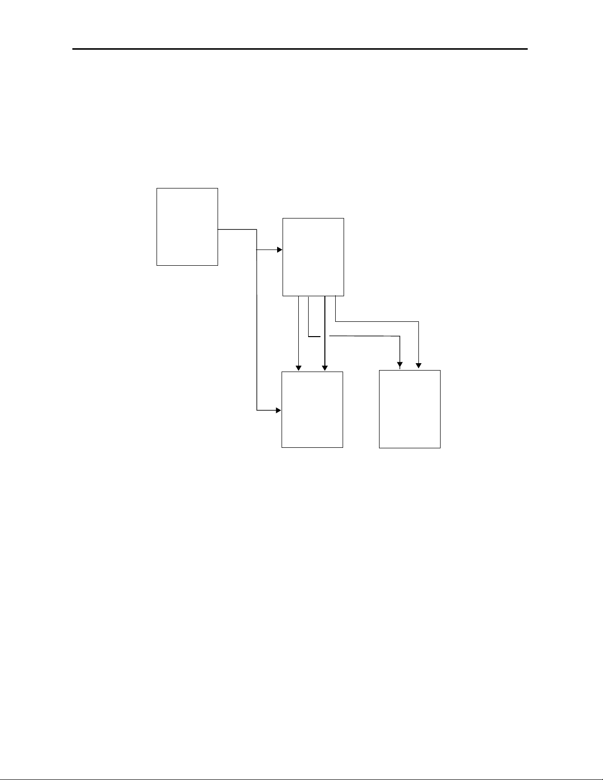
As shown in the block diagram below, the selected reference enters a sync detector circuit
where information is extracted to determine the format and create the correct synchonizing pulses for the timing generator. The timing generator is used by the test signal
generator to synchonize the black and pattern generators. The serializers convert the
parallel data stream to a serial differential pair which then passes to the output drivers.
The output drivers feed four identical copies of the selected test signal to BNCs on the
rear of the module. Two identical copies of the black signal are also available.
Power is derived from the ± 12 volt frame power. It is regulated to the required +5 volts
for the module by on-board regulator. The module is fused with a resettable fuse device. If
the fuse opens due to an overcurrent condition, the module will lose power. After pulling
the module, the fuse will reset automatically requiring no replacement fuse.
The on-board CPU can monitor and report module ID information (slot location, software
version and board revision), and power status to the optional frame System Control
module. This information can be accessed by the user or set to register an alarm if desired
using the remote control options available. The CPU also communicates with the remote
control system.
Model 7405 HD Test Signal Generator
7405-2
7405 HD TSG Block Diagram
External
Ref
Master
Ref
Sync
Detector
Timing
Gen
Black
Gen
Pattern
Gen
Pattern
Storage
Serializer
Serializer
HD Black Outputs
HD TSG Outputs
Avenue Control System
Module
controller
Page 3
Model 7405 HD Test Signal Generator
APPLICATIONS
Test Signal and Black Distribution
As shown in the application below, the 7405 module can provide stable HD test signals to
facility HD routers and HD production switchers. An Avenue 5400 Dual Sync Generator
can provide the Tri-level or SD composite sync reference for the 7405 and then be looped
to the HD production switcher and other destinations if required.
7405-3
7405 Providing HD Test Signals
5400
Sync
Generator
HD
TL Sync
7405
HD
TSG
HD Black
HD
Test
Siganal
HD
Production
Switcher
HD Test Siganal
HD Black
HD
Router
Page 4
INSTALLATION
Plug the 7405 module into any one of the slots in the 1 RU or 3 RU frame. Install the
plastic overlay provided onto the corresponding group of rear BNC connectors associated
with the module location. Note that the plastic overlay has an optional adhesive backing
for securing it to the frame. Use of the adhesive backing is only necessary if you would
like the location to be permanent and is not recommended if you need to change module
locations. This module may be hot-swapped (inserted or removed) without powering down
or disturbing performance of the other modules in the system.
CABLING
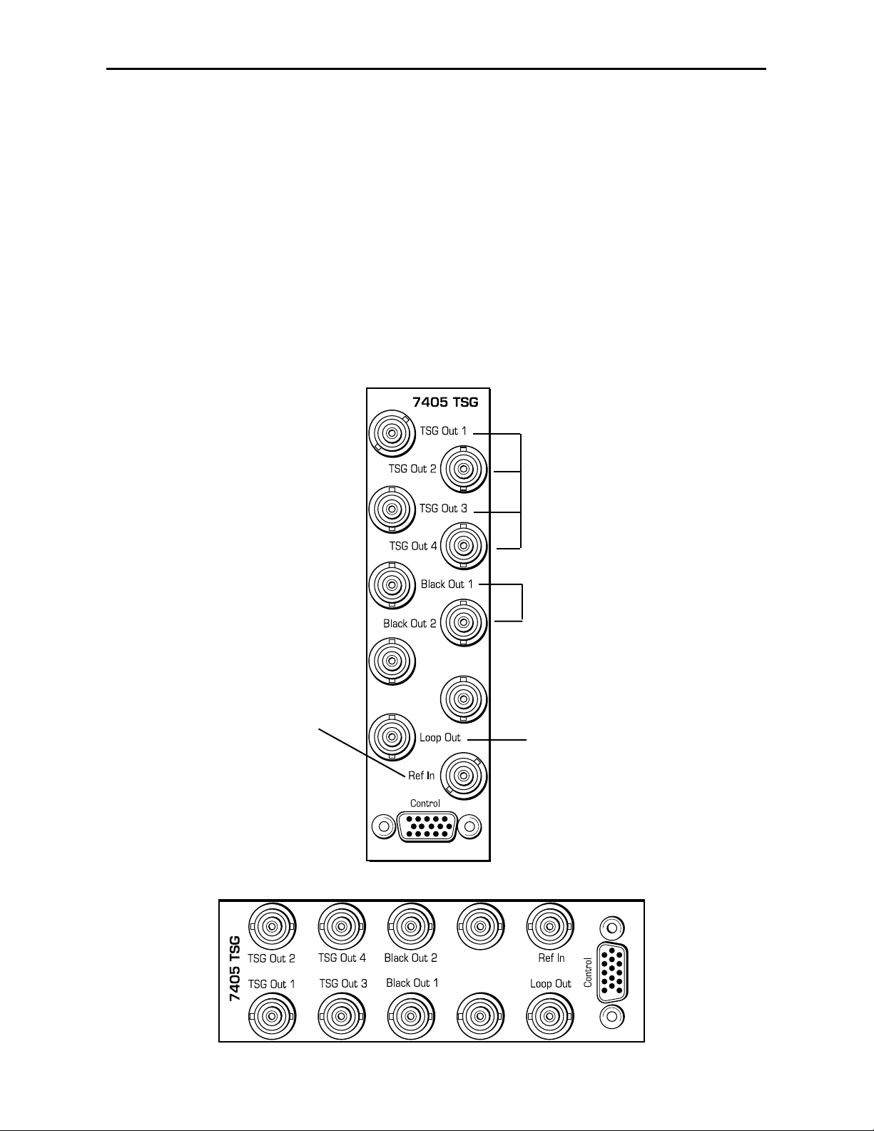
Refer to the 3 RU and 1 RU backplane diagrams of the module below for cabling instructions. Note that unless stated otherwise, the 1 RU cabling explanations are identical to
those given in the 3 RU diagram.
7405-4
Model 7405 HD Test Signal Generator
3 RU Backplane
Connect a Tri Level or
SD Composite (525 or
625) sync reference
signal to the Ref In BNC.
(This input is required
when the module is used
in Local mode.)
Connect the four copies of the
HD test signal on BNCs TSG
OUT 1 – 4 to high definition
destinations.
Connect the two copies of the
Black test signal output on
BNCs Black Out 1-2 to high
definition destinations.
Loop the reference signal
input to other destinations
from the Loop Out BNC.
1 RU Backplane
Page 5

MODULE CONFIGURATION AND CONTROL
The configuration parameters for each Avenue module must be selected after installation.
This can be done remotely using one of the Avenue remote control options or locally using
the module front panel controls. Each module has a REMOTE/LOCAL switch on the
front edge of the circuit board which must first be set to the desired control mode.
The configuration parameter choices for the module will differ between Remote and
Local modes. In Remote mode, the choices are made through software and allow more
selections. The 7405 Parameter Table on the following page summarizes and compares
the various configuration parameters that can be set remotely or locally and the
default/factory settings.
If you are not using a remote control option, the module parameters must be configured
from the front panel switches. Parameters that have no front panel control will be set to a
default value. The Local switches are illustrated in the Front Panel Controls and
Indicators section following the 7405 Parameter Table.
Avenue module parameters can be configured and controlled remotely from one or both of
the remote control options, the Avenue Touch Screen or the Avenue PC Application. Once
the module parameters have been set remotely, the information is stored on the module
CPU. This allows the module be moved to a different cell in the frame at your discretion
without losing the stored information. Remote configuration will override whatever the
switch settings are on the front edge of the module.
For setting the parameters remotely using the Avenue PC option, refer to the Avenue PC
Remote Configuration section of this document.
For setting the parameters remotely using the Avenue Touch Screen option, refer to the
Avenue Touch Screen Remote Configuration section of this data pack following
Avenue PC.
Model 7405 HD Test Signal Generator
7405-5
Page 6
Model 7405 HD Test Signal Generator
7405-6
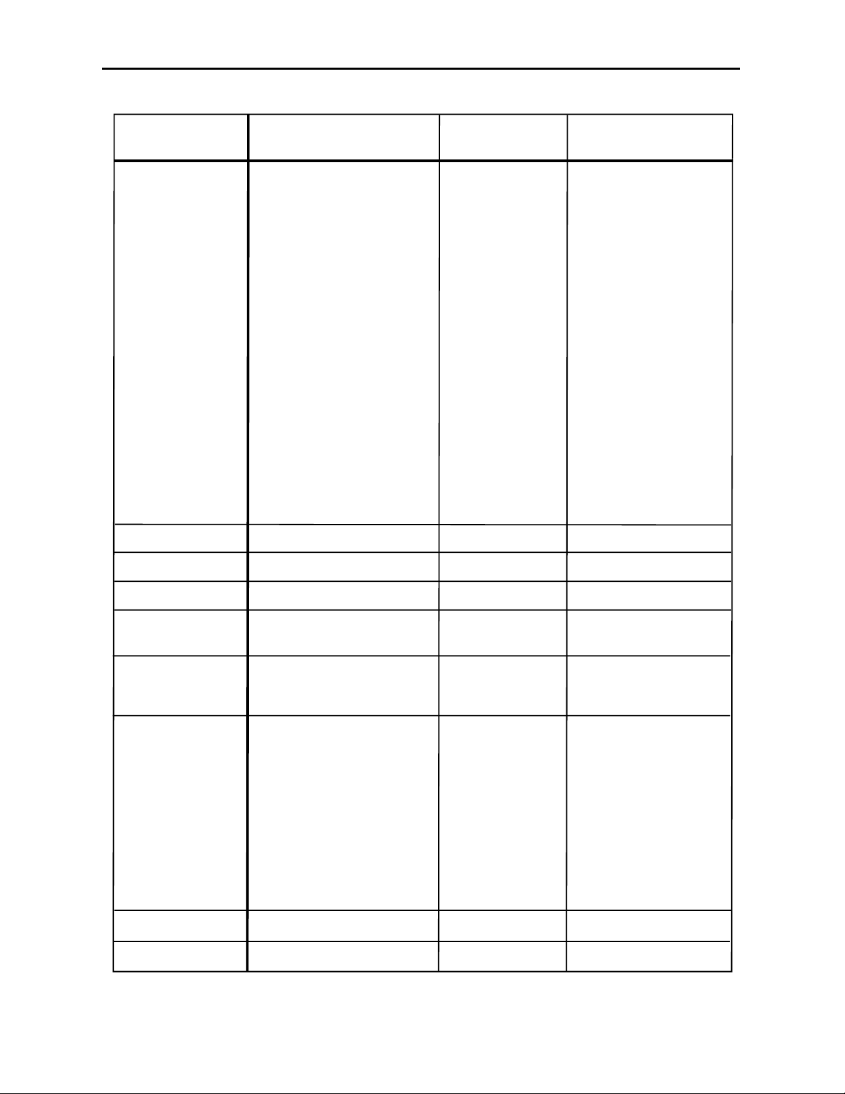
7405 Parameter Table
CONTROL REMOTE LOCAL DEFAULT/FACTORY
Pattern Type
Y Channel
Cr
Rotary Switch:
1 Black
2 100% Bars
3 SMPTE Bars
4 Pulse & Bar
5 Crosshatch
6 Safe Area
7 Aspect Ratio
8 Cosite Pulse
9 Data Ramp
10 Pathological
N/A
N/A
Bars:
Split Field 75
Split Field 100
Mon Align
Full Field 75
Full Field 100
Black:
Black
Flat Field 50
Ramp:
Data Ramp
5 Step
Pulse & Bar:
Window
Timing:
Blanking
Cosite
Misc:
Black
CrossHatch
Aspect
Safe Title
Checkfield
Enabled/Disabled
Enabled/Disabled
Bars/Split Field 75
Enabled
Enabled
Cb
Ref Select
Ref Type
Output Std
Vertical Timing
Horizontal Timing
N/A
Switch 1: TL (left)
Blk (right)
Ext reference only must match
Output Std selected below and
be connected to Ref In BNC
Switch 2: 1080 (left)
720p (right)
When Switch 2 is in 1080:
Switch 3: 1080i (left)
1080sF (right)
The Frame/Line rate follows
the external reference input.
Note: No 1080p in Local Mode
N/A
N/A
Enabled/Disabled
Ext Video
Master Ref
SD Composite
HD Tri-Level
720p/50 Hz
720p/59.94 Hz
720p/60 Hz
1080i/50 Hz
1080i/59.94 Hz
1080i/60 Hz
1080p/23.98 Hz
1080p/24 Hz
1080p/25 Hz
1080sF/23.98 Hz
1080sF/24 Hz
1080sF/25 Hz
+/- 575 Lines
+/- 2400 Clks
Enabled
Ext Video
SD Composite
1080i/59.94 Hz
0
0
Page 7

Front Panel Controls and Indicators
Each front edge indicator and switch setting is shown in the diagram below:
7405-7
Remote/Local switch:
Set to the mode you
will be using.
Pwr green LED:
Indicates the presence (ON) or
absence (OFF) of power (+5V).
Run green LED:
OFF:
A power fault or halted CPU.
ON:
A halted CPU.
FAST BLINK:
CPU Run error.
SLOW BLINK:
System OK. (If SPI control is
active from the main frame
System Control Module, all
Run indicators will be synchronized.).
Ref green LED:
On when selected input
reference is present and
locked to output. Off when
unlocked.
Model 7405 HD Test Signal Generator
Lock Error red LED:
On when the output is
not locked to the
selected reference.
Ref (Reference)
TL/Blk switch:
Set the reference type for TL, Tri-
Level, (left) or Blk, SD Composite,
(right). The reference source is the
Ref In BNC on the rear of the 7405.
Note: For correct locking in TL, the
Tri-level reference connected must
match the HD output standard.
When Blk (SD Composite ) is
selected, the line rate of the HD
output will automatically match the
reference.
1080/720p
switch:
Select output standard for either
1080 (left) or 720p (right).
1080i/sF switch:
When switch above is set for 1080,
set the switch for 1080i (left) or
1080sF (right).
Note: 1080p is not available in
Local mode.
Pattern select switch:
Select one of the HD test signal
patterns listed with the rotary
switch.
Page 8

Avenue PC Remote Configuration
The Avenue PC remote control status menu for this module is illustrated and explained
below. Refer to the 7405 Parameter Table for a summary of available parameters that
can be set remotely through the menus illustrated. For more information on using Avenue
PC, refer to the Avenue PC Control Application Software data pack that came with the
option.
7405 Avenue PC Menus
The Patterns menu shown below allows you to set the type of test pattern desired for the
TSG outputs with the following controls:
• Pattern Type – select the HD test signal type in the first window and the test
signal parameters in the second window. Refer to the 7405 Parameter Table
shown earlier for a complete listing of the available test signals and their parameters. Refer to Appendix A for a complete description of each test pattern.
• Y, Cr, Cb Enabled – deselect to turn off the Y, Cr and/or Cb Channels of the
selected pattern type for test purposes (such as the need for a monochrome signal
for example). To turn off one or more channels, deselect the Enabled check box.
7405-8
Model 7405 HD Test Signal Generator
Page 9

The Config menu screen shown below allows you to select the module reference, the
reference type, and the HD output standard for the test signal with the following controls:
• Ref Select – select the source of the reference from Master Ref from the Avenue
frame or the Ext Video reference connected to the Ref In BNC on the rear of the
7405 module.
• Ref Type – select the reference type from SD Composite (525/NTSC or 625/PAL)
or HD Tri-Level.
• Output Std – select the output standard for the test signal. Refer to the 7405
Parameter Table shown earlier for a complete listing of the available test signal
standards.
Refer to the locking rules outlined below for setting the reference remotely:
• When the reference type selected is SD Composite, you may use either 525/NTSC
or 625/PAL with any HD output standard and the generator will always lock to the
reference. The signals however may not be vertically coincident. To guarantee the
HD output will be vertically coincident with the reference, use the following guidelines:
For 525/NTSC reference – set the HD output standard to one of the following:
720p/59.94 Hz
1080i/59.94 Hz
1080p/23.98 Hz
1080sF/23.98 Hz
For 625/PAL reference – set the HD output standard to one of the following:
720p/50 Hz
1080i/50 Hz
1080p/50 Hz
1080sF/25 Hz
• When the reference type selected is HD Tri-level, the incoming HD Tri-level
reference (either Master Ref or Ext Video) must be the same as the selected HD
output standard or a lock error will occur.
Model 7405 HD Test Signal Generator
7405-9
Page 10

Model 7405 HD Test Signal Generator
The Timing menu screen shown below allows you to set the timing of the test and black
signal outputs relative to the reference signal:
• Vertical – adjust the vertical timing of the test signal and black output relative to
the selected reference.
• Horizontal – adjust the horizontal timing of the test signal and black outputs
relative to the selected reference.
7405-10
Page 11

Model 7405 HD Test Signal Generator
Avenue Touch Screen Remote Configuration
The Avenue Touch Screen remote control status menu for this module is illustrated and
explained below. Refer to the 7405 Parameter Table for a summary of available parameters that can be set remotely through the menus illustrated. For more information on
using Avenue Touch Screen, refer to the Avenue Touch Screen data pack that came with
the option.
7405 Avenue Touch Screen Menus
The Patterns menu shown below allows you to set the type of test pattern desired for the
TSG outputs with the following controls:
• Pattern Type – select the HD test signal type in the first window and the test
signal parameters in the second window. Refer to the 7405 Parameter Table
shown earlier for a complete listing of the available test signals and their parameters. Refer to Appendix A for a complete description of each test pattern.
• Y, Cr, Cb Enabled – deselect to turn off the Y, Cr and/or Cb Channels of the
selected pattern type for test purposes (such as the need for a monochrome signal
for example). To turn off one or more channels, deselect the Enabled check box.
7405-11
Page 12

The Config menu screen shown below allows you to select the module reference, the
reference type, and the HD output standard for the test signal with the following controls:
• Ref Select – select the source of the reference from Master Ref from the Avenue
frame or the Ext Video reference connected to the Ref In BNC on the rear of the
7405 module.
• Ref Type – select the reference type from SD Composite (525 – NTSC or
625/PAL) or HD Tri-Level.
• Output Std – select the output standard for the test signal. Refer to the 7405
Parameter Table shown earlier for a complete listing of the available test signal
standards.
Refer to the locking rules outlined below for setting the reference remotely:
• When the reference type selected is SD Composite, you may use either 525/NTSC
or 625/PAL with any HD output standard and the generator will always lock to the
reference. The signals however may not be vertically coincident. To guarantee the
HD output will be vertically coincident with the reference, use the following guidelines:
For 525/NTSC reference – set the HD output standard to one of the following:
720p/59.94 Hz
1080i/59.94 Hz
1080p/23.98 Hz
1080sF/23.98 Hz
For 625/PAL reference – set the HD output standard to one of the following:
720p/50 Hz
1080i/50 Hz
1080p/50 Hz
1080sF/25 Hz
• When the reference type selected is HD Tri-level, the incoming HD Tri-level
reference (either Master Ref or Ext Video) must be the same as the selected HD
output standard or a lock error will occur.
Model 7405 HD Test Signal Generator
7405-12
Page 13

7405-13
The Timing menu screen shown below allows you to set the timing of the test and black
signal outputs relative to the reference signal:
• Vertical – adjust the vertical timing of the test signal and black output relative to
the selected reference.
• Horizontal – adjust the horizontal timing of the test signal and black outputs
relative to the selected reference.
Model 7405 HD Test Signal Generator
Page 14

TROUBLESHOOTING
As a troubleshooting aid, the reference signal status and presence, any locking errors,
power and CPU status can be easily monitored from the front panel of this module using
the front panel indicators.
Refer to the overall troubleshooting tips given below for the module:
Ref LED is not lit on front panel:
• Reference is not present on Master Ref input to frame or Ref In external
video BNC.
Lock Error LED is lit on front panel:
• Tri-level reference input does not match the selected HD output standard.
Can’t control module:
• Check status of CPU Run green LED. Should be blinking slowly and in
unison with other modules if System module is present. If not, try removing
it and plugging it in again to be sure it is seated properly.
• System module may not be working properly if installed.
No signal out of module:
• Check status of Ref green LEDs. One should be lit. If not, check the
reference input or master frame signal for presence and quality.
• Check cabling to input of module.
You may also refer to the technical support section of the Ensemble Designs web site for
the latest information on your equipment at the URL below:
http://www
.ensembledesigns.com/support
SOFTWARE UPDATING
Software upgrades for each module can be downloaded remotely if the optional System
Control module is installed. These can be downloaded onto your PC and then Avenue PC
will distribute the update to the individual module. (Refer to the Avenue PC documentation for more information) Periodically updates will be posted on our web site. If you do
not have the required System Control Module and Avenue PC, modules can be sent back
to the factory for software upgrades.
Model 7405 HD Test Signal Generator
7405-14
Page 15

Model 7405 HD Test Signal Generator
7405-15
WARRANTYAND FACTORY SERVICE
Warranty
This module is covered by a five year limited warranty, as stated in the main Preface of
this manual. If you require service (under warranty or not), please contact Ensemble
Designs and ask for customer service before you return the unit. This will allow the
service technician to provide any other suggestions for identifying the problem and
recommend possible solutions.
Factory Service
If you return equipment for repair, please get a Return Material Authorization Number
(RMA) from the factory first.
Ship the product and a written description of the problem to:
Ensemble Designs, Inc.
Attention: Customer Service RMA #####
870 Gold Flat Rd.
Nevada City, CA. 95959 USA
(530) 478-1830
Fax: (530) 478-1832
service@endes.com
http://www.ensembledesigns.com
Be sure to put your RMA number on the outside of the box.
Page 16

SPECIFICATIONS
7405 HD Test Signal Generator
Output:
Number: Six (4 test signal, 2 black)
Signal Type: HD Serial Digital
Impedance: 75 ohm
Return Loss: >15 dB DC to 1.5 GHz
Standards Supported: 1080i (SMPTE 274M-4, 5, 6) 50, 59.94, or 60 Hz
720p (SMPTE 296M-1, 2, 3) 59.94 or 60 Hz
1080p (SMPTE 274M-9, 10, 11) 23.98, 24, 25 Hz
1080sF (RP211-14, 15, 16) 23.98, 24, 25 Hz
Reference Input:
Number: One external (Ref In BNC on module)
One internal (Frame’s Master Reference BNC)
Signal Type: PAL or NTSC composite video or HD Tri-level Sync
Return Loss: >40 dB (applies to external reference input)
Test Signals:
Bars: Split Field 75
Split Field 100
Mon Align
Full Field 75
Full Field 100
Black: Black
Flat Field 50
Ramp: Data Ramp
5 Step
Pulse & Bar: Window
Timing: Blanking
Cosite
Misc: Black
Crosshatch
Aspect
Safe Title
Checkfield
General Specifications:
Power Consumption: < 7 Watts
Temperature Range: 0 to 40 degrees C ambient (all specs met)
Relative Humidity: 0 to 95%, noncondensing
Altitude: 0 to 10,000 ft.
Due to ongoing product development, all specifications subject to change.
Model 7405 HD Test Signal Generator
7405-16
Page 17

APPENDIX A
This appendix is provided to give details on each of the test patterns available on the 7405
module. Section A.1 lists the test patterns provided and Section A.2 provides a description
of the test patterns.
A.1 Test Patterns
All of the test patterns listed are available when using an Avenue remote control options
such as Avenue PC or a Touch Screen Panel. The ten patterns that are available in Local
mode are identified with the corresponding rotary switch position for selecting them.
Color Bars
Split Field 75%
Split Field 100%
Mon Align (SMPTE Bars) (Rotary Switch Setting 3)
Full Field 75%
Full Field 100% (Rotary Switch Setting 2)
Black
Black (Rotary Switch Setting 1)
Flat Field 50
Ramp
Data Ramp (Rotary Switch Setting 9)
5 Step
Pulse & Bar
Window (Rotary Switch Setting 4)
Timing
Blanking
Cosite (Rotary Switch Setting 8)
Miscellaneous
Black
CrossHatch (Rotary Switch Setting 5)
Aspect Ratio (Rotary Switch Setting 7)
SafeTitle (Rotary Switch Setting 6)
Checkfield (Rotary Switch Setting 10)
Model 7405 HD Test Signal Generator
7405-A1
Page 18

A.2 TEST PATTERN DESCRIPTIONS
Bars Test Patterns
All of the color bar patterns include peak white, black, and the six vector colors (yellow,
cyan, green, magenta, red, and blue), either at 75% or 100%.
Split Field Bars
Pluge and level reference is added to the color bars to make a split field. The pluge
is used to adjust monitor brightness and to check for clipping in digital systems.
The pluge includes +/- 2 IRE levels around black, four luminance steps, and a 5
IRE "top hat" above peak white.
In composite systems, monitor brightness can be adjusted using the +/- 2 IRE
levels around black by making the right-most level disappear in the adjacent black
while making the left-most level just visible.
In digital systems, the number of steps of dynamic range is limited by the number
of bits used to represent them. Black is represented by 040h and white is represented by 3ACh. If clipping occurs in the digital processing of a signal, the "top
hat" and/or the 2 IRE superblack level can be clip off.
Full Field Bars
Full field bars is sometimes called simple bars as it does not include anything else.
It is color bars from the top of the field to the bottom.
100% is usually used for component signals as the amplitude of the Cb and Cr
signals is the same as the Y signal. A waveform monitor can be used to align Y, Cb,
and Cr gain.
75% is more commonly used with composite--when viewed on a waveform monitor,
the chroma yellow and cyan envelope is lined up with the peak white level. As
such, a waveform monitor can be used to align luminance and chrominance gain,
and a vector display can be used to align chroma phase.
Mon Align (SMPTE Color Bars)
SMPTE Color Bars has a reverse sequence of bars to help adjust monitor levels on
monitors that provide blue only displays. Hue can be aligned by balancing the
chroma bars, and chroma can be set by matching the chroma bars to the white
bars. It also includes pluge.
Mon Align
In addition to pluge, SMPTE Color Bars includes a reverse sequence of bars.
The reverse sequence helps adjust monitor levels on monitors that provide blue
only displays. Hue can be aligned by balancing the chroma bars, and chroma can
be set by matching the chroma bars to the white bars.
7405-A2
Model 7405 HD Test Signal Generator
Page 19

Black Test Patterns
These test patterns are field field luminance reference levels. Black can be used as a color
black reference signal and the others can be used as flat luminance mattes.
Black
The HD black test pattern is a full-field black signal.
Flat Black 50
A 50 percent black signal creating a gray signal for applications requiring a
neutral background.
Ramp Test Patterns
Ramp test patterns are very useful for evaluating linearity, missing bits, timing errors,
and dynamic range.
If there is a problem with linearity, the ramp will not be a straight line. If there is a
missing bit, the ramp will be broken up into smaller ramps. If there is a timing error,
vertical lines which are often noisy can appear. If there is a dynamic range problem,
clipping will occur at the top or the bottom of the ramp.
Data Ramp
The data ramp test pattern goes from minimum to maximum legal digital values
in one step per sample increments. The ramp therefore restarts part of the way
across the line. Because it uses the entire dynamic range, it is especially useful to
check for clipping in each of the component channels, Y, Cb, and Cr.
5 Step Ramp
The five step ramp test pattern has five steps used for aligning display systems
such as a projector.
Pulse and Bar Test Patterns
This test pattern is used to evaluate transient response and clamp performance. Chromato-luminance delay, short-term distortion, gain, response, and tilt can be measured.
Window
The window test pattern is comprised of a 2T pulse, a modulated 12.5T pulse and a
window bar.
The 2T pulse is used to measure short term distortion such as K2T, and transient
response such as KPB.
The modulated 12.5T pulse is used to evaluate chroma-to-luminance delay. When
viewed on a monitor, the bottom of the chroma envelope ideally appears as a flat
line. Group delay can distort the bottom of the envelope and, with the appropriate
waveform monitor graticule, can be measured.
The bar can be used to measure gain, and is also used to measure short-term distortion such as K
SD
and tilt such as K
BAR
.
7405-A3
Model 7405 HD Test Signal Generator
Page 20

Timing Test Patterns
Timing test patterns are used to evaluate blanking area, field location, relative luma and
chroma timing, and cositing.
Blanking Markers
The analog blanking markers test pattern draws a box around each field to show
the limits of blanking in composite systems. The size of the box is different for
NTSC than for PAL. In NTSC, the top of the field is at 21/284 and the bottom is at
262/525. In PAL, the top of the field is at 24/337 and the bottom is at 310/622.
The left and right markers are separated from digital blanking, which is narrower,
by a step so that actually blanking edges can be observed after passing through a
process that imposes blanking.
Cosite
The cosite test pattern assists in determining that the luminance and chrominance
parts of a digital signal are occurring in the appropriate relative time.
The vertical magenta pinstripe consists of a single cosite pulse in Y, Cb and Cr.
Because they are cosited and are only one sample wide, a mistiming of these components will not appear magenta on a monitor. Cb and Cr can be determined easily
on a waveform monitor because Cb is smaller than Cr. The levels are as follows:
Y-1B7h, Cb-3C0h, Cr-340h. The pinstripe is also useful because it is in the middle
of the line.
Miscellaneous Test Patterns
The following test patterns have special purposes.
Black
A standard black signal.
Crosshatch
The crosshatch test pattern consists of horizontal and vertical lines organized in a
grid. This test pattern is used to evaluate monitor linearity and distortion.
SafeTitle
The safetitle test pattern identifies safe area in a video monitor for titles. If the
title stays inside the safe area, then monitors will always show the complete title
uncropped. The safe title pattern also shows the center of the visible area.
Aspect Ratio
When viewed on a component vectorscope, the unit circle test pattern displays a
circle of constant radius. This test pattern is useful for evaluating systems that
manipulate chroma such as chroma keyers.
Checkfield
The checkfield or pathological test pattern consists of a flat field of magenta color
that is precisely chosen because it produces long sequences of ones and zeroes in
serial digital systems. Because some systems are not tolerant of long sequences,
this pattern can help to identify those systems. This test signal is very useful for
testing transmission paths.
When a pathological error occurs, this test pattern shows horizontal, intermittent
black lines.
7404-A4
Model 7405 HD Test Signal Generator
 Loading...