

Page 1
This data pack provides detailed installation, configuration and operation information for
the 6600 Frame, 6601 and 6601R Analog Audio Distribution Amplifiers as part of
the Avenue Signal Integration System.
The module information in this data pack is organized into the following sections:
• Important Safety Instructions
• 6600 Overview
• 6600 Frame
°
Frame Description
°
Power Supplies
°
Frame Installation
• 6601 Analog Audio Distribution Amplifier
• 6601R Analog Audio Distribution Amplifier
• Warranty and Factory Service
• Specifications
• Additional Warnings and Cautions
6600-1
Model 6600 Frame
6601 and 6601R
Analog Audio DAs
Data Pack
Revision 2.0 SW v1.0.0
ENSEMBLE
DESIGNS
Page 2

IMPORTANT SAFETY INSTRUCTIONS
Read these instructions.
Keep these instructions.
Heed all warnings.
Follow all instructions.
Do not use this equipment near water.
Clean only with dry cloth.
Do no block any ventilation openings. Install in accordance with the equipment
instructions.
Do not install near any heat sources such as radiators, stoves or other apparatus that
produce heat.
Do not defeat the safety purpose of the grounding-type plug. A grounding-type plug has
two blades and third grounding prong. If the provided plug does not fit into your outlet,
consult an electrician for replacement of the obsolete outlet.
Protect the power cord from being walked on or pinched, particularly at plugs, convenience
receptacles and the point where they exit from the apparatus.
Only use attachments and accessories specified by Ensemble Designs.
Unplug this equipment when not used for long periods of time.
Refer all servicing to qualified service personnel. Servicing is required
when the equipment has been damaged in any way, such when a powersupply cord is damaged, liquid has been spilled or subjects have fallen
into the equipment, the equipment has been exposed to rain or moisture,
does not operate normally, or has been dropped.
Risk of electric shock. Qualified service personnel should only access
power supply after frame has been unplugged from power.
If the equipment is installed in a moveable cart, use caution when
moving the equipment to avoid injury from tip-over.
Model 6600 Analog Audio DAs and Frame
6600-2
Page 3
6600 OVERVIEW
The 6600 series of analog audio modules provide high performance analog distribution in
a 2 RU frame with a standard and an optional redundant power supply. The 6600 frame is
dedicated to audio distribution and pluggable terminal strips are standard on every frame.
There is no need for rear modules or special adaptors. Power supplies can be removed
from the front of the frame.
Two analog audio distribution modules are available: the 6601 Analog Audio Distribution
Amplifier (DA) and the 6601R Analog audio DA (with remote gain control).
The 6601 Analog Audio DA module is a high performance audio distribution amplifier for
the broadcast and recording industry. Exceptional performance features include excellent
response, noise and distortion specifications.
The 6601R Analog Audio DA module has all the capability of the 6601 plus selectable
remote gain control. The amplifier offers a ± 20 dB remotely controlled audio gain, which
is selectable to either remote or local.
Both DA modules can be configured as mono or stereo, the 6600 with 8 balanced outputs
(mono) or 4 balanced outputs per channel (stereo) and the 6601R with 6 balanced outputs
(mono) or 3 balanced outputs per channel (stereo). The mode is selected with a jumper on
each module.
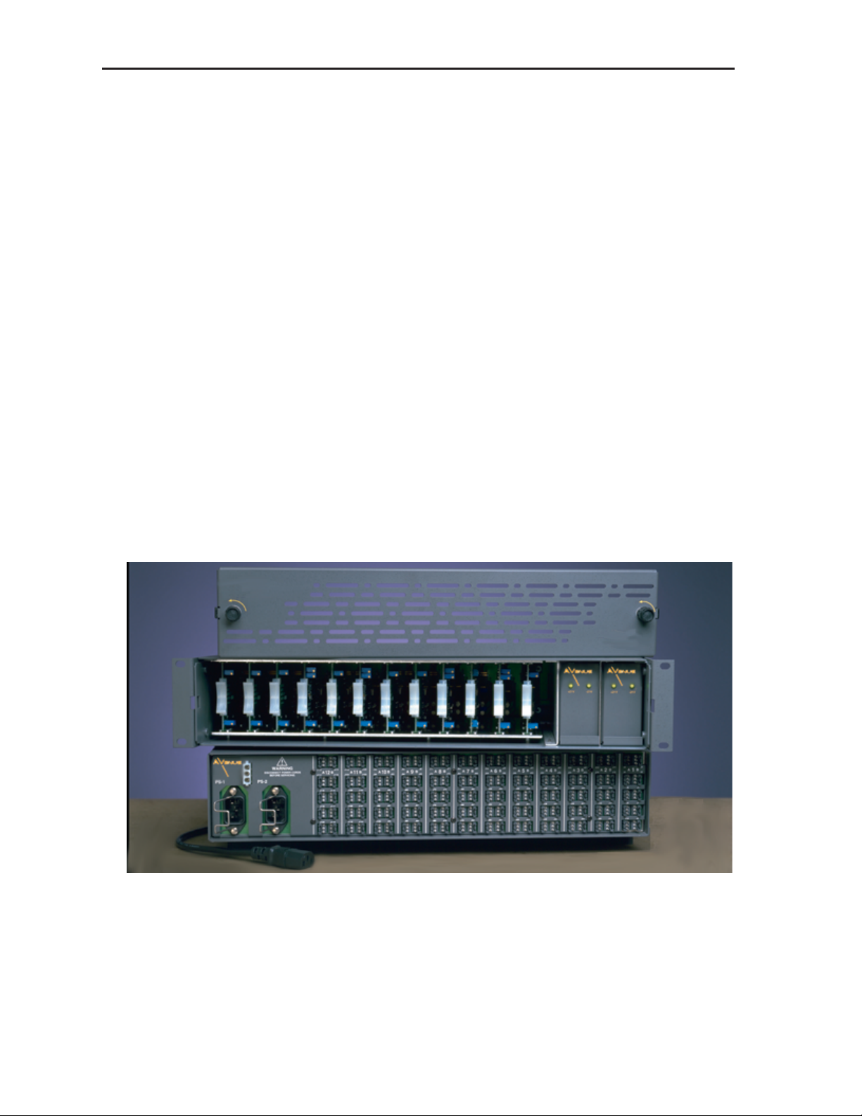
Up to twelve 6601 or 6601R audio amplifiers can be mounted in the 2 RU Avenue 6600
frame in any combination. The front and rear views of the 6600 frame with removable
vented cover is shown in the figure below.
Model 6600 Analog Audio DAs and Frame
6600 Analog Audio 2 RU Avenue Frame
6600-3
Page 4
6600 FRAME
Frame Description
The Avenue 6600 2 RU rack mountable audio frame is capable of housing up to twelve
6601/6601R analog audio distribution modules. Input and output signal connections and
remote gain controls are provided with removable clamp-type barrier connectors.
Power Supplies
The frame provides mounting space for up to two PS66 power supplies for providing DC
power to the frame. The supply is auto-sensing and will operate from any input voltage in
the range 90 to 260 VAC with a frequency of 50 or 60 Hz. The supply provides ± 21V @ 40
Watts. If the power required by the frame exceeds 30 Watts, it is recommended that two
supplies be used to improve heat dissipation and reliability.
Two supplies powered from separate AC sources are always recommended to maximize
reliability. The actual power drawn from the AC supply will depend on how many amplifiers and of what type are in the frame. It may be necessary to use dual supplies if the
frame is fully loaded with higher current options (see each amplifier section of this
manual).
A 3-pin Molex connector is provided on the rear of the frame. It is connected to the plus
and minus output DC rails of the power supply and can be wired to another 6600 frame.
This will provide power redundancy for the second frame without the need to purchase a
redundant supply for that frame.
Frame Installation
The Avenue 6600 frame requires 2 RU of space (3.5 in.) and is intended to be mounted in
a standard 19 in. rack. The horizontal depth required in the rack is 12.5 in. and additional
space behind the frame should be planned for audio wiring. No special cooling requirements are necessary, but it is desirable to avoid mounting the frame adjacent to highspeed digital units to avoid possible noise problems.
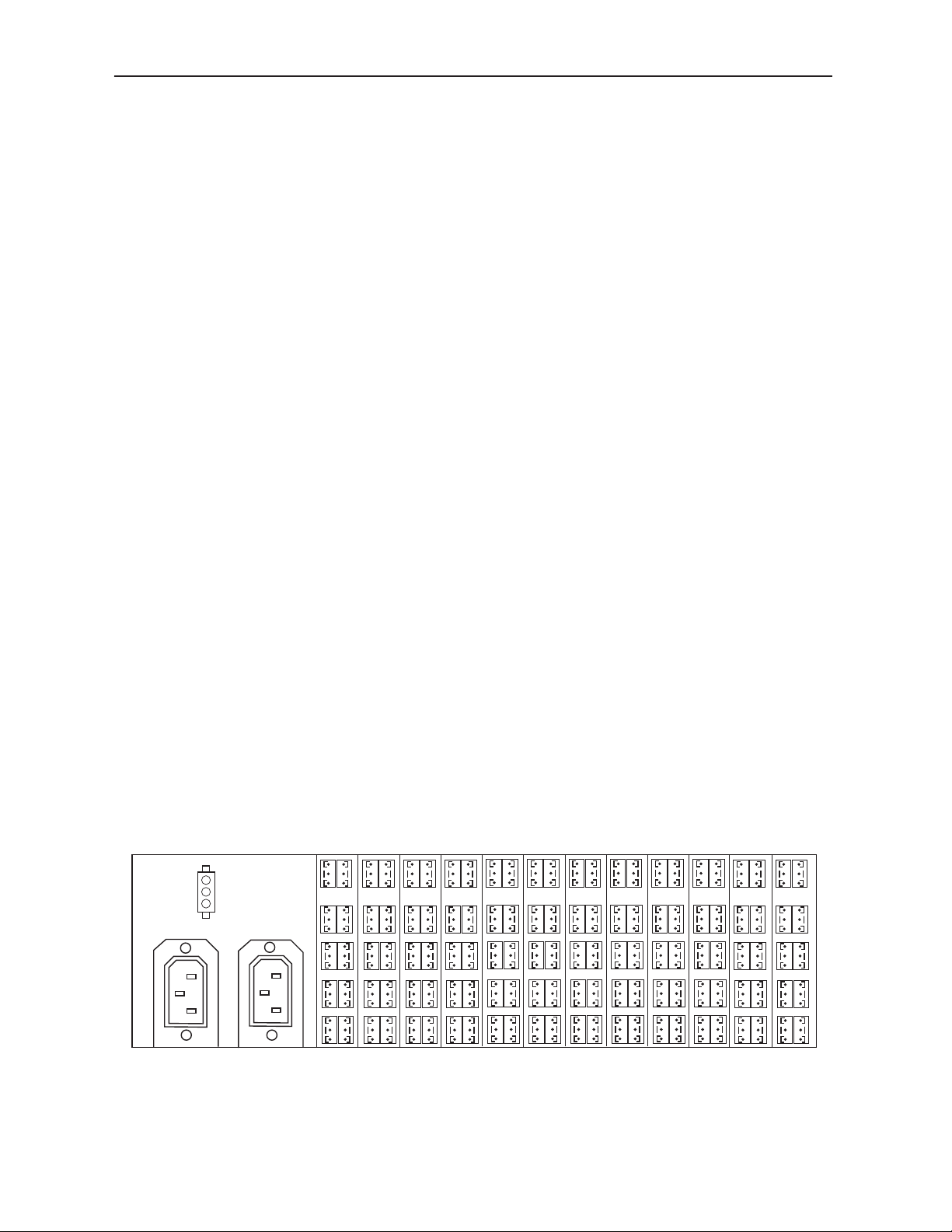
The frame input and output connections are similar for the 6601/6601R audio modules.
The typical installation consists of groups of three-pin terminal blocks as illustrated in the
frame rear view below. Refer also to the appropriate amplifier section of this manual for
the actual frame inter-connections.
Model 6600 Analog Audio DAs and Frame
6600-4
A 12 B A 11 B A 10 B A 9 B
A 8 B A 7 B A 6 B A 5 B A 4 B A 3 B
A 2 B A 1 B
PS–1
PS–2
+ 21V
– 21V
Frame Rear View – 3-pin Terminal Wiring
Page 5

Model 6600 Analog Audio DAs and Frame
6600-5
6601 ANALOG AUDIO DA
Description
The 6601 Analog Audio Distribution Amplifier (DA) is a modular, high performance audio
distribution amplifier intended for studio quality audio distribution systems. It is
designed to be operated from the 6600 audio mounting frame.
The module can be configured as a 1 input by 8 output monaural, or as two, 1 input by 4
output stereo amplifiers, just by moving one internal jumper. In the MONO mode only the
Channel A input connectors are used.; the Channel B input is left unconnected.
All inputs can be connected balanced or unbalanced. Outputs are always balanced. Both
preset and variable gain controls are available which will provide a gain range of – 6 to
+ 33 dB.
Each module has its own on-board voltage regulators with fuse protection. Any failure of a
single module will not effect any other.
Installation
The 6600 audio distribution amplifier is designed to be mounted in the 6600 audio
mounting frame, (up to twelve modules can be installed). There are no special cooling
requirements, although care should be taken to ensure that extremely hot equipment is
not installed directly beneath the frame.
It is recommended that when redundant power supplies are included in the frame, the
two power cords be connected to different AC supplies. In this way the frame will continue
to operate even if there is a partial failure of plant power.
Before installing the module in the frame, it is necessary to set three internal jumpers to
the desired mode. Jumper H2 selects either MONO or STEREO mode, and jumpers H1
and H3 set the desired gain of each channel. Jumpers and gain controls are illustrated in
the figure below.
+27 dB
+18 dB
+9 dB
0 dB
+27 dB
+18 dB
+9 dB
0 dB
H1
RV3
RV1
RV2
RV4
MONO
STEREO
H3
H2
CH A GAIN CH B GAIN
CH B BALANCE
CH A BALANCE
6601 Component Side View
Page 6

Circuit Description
The 6600 module consists of two identical input circuits and two identical groups of four
output circuits. A jumper (H2) permits the two output channels to be both connected to
one input channel for use as a one input, eight output monaural amplifier or a two
channel, four output stereo amplifier.
Since both input amplifiers are the same, only the A channel will be described.
The differential input signal is applied to the inverting inputs of U3:A and U3:B. An
inverted version of the common mode signal (if any) is also applied to these inputs from
U6:A such as to cancel any common mode component at the outputs of U3:A and U3:B.
The outputs from U3:A and U3:B are then applied to the differential amplifier, U6:B.
Optimum common mode balance is achieved by adjusting RV3 at the output of U6:A.
The output from the differential amplifier passes via the gain control potentiometer, RV1,
to the programmable gain amplifier, U5:A. This amplifier provides fixed gains of 0dB,
+9dB, +18dB and +27dB. The desired gain is set by H1.
Cabling
Audio input and output cabling consists of 3-pin terminal blocks as shown in the illustration below. For MONO operation, connect audio to the CH A input only and use the eight
monaural outputs. For STEREO operation, connect audio to the CH A and CH B inputs
and use the four CH A and four CH B outputs as shown. Connectors grayed out are not
used for the application.
Model 6600 Analog Audio DAs and Frame
6600-6
A 1 B
+
+
+
+
+
+
+
+
+
+
J1
J3
J2
J4
J6
J5
J7
J9J10
J8
A 1 B
+
+
+
+
+
+
+
+
+
+
J1
J3
J2
J4
J6
J5
J7
J9J10
J8
1 Input
8 Outputs
A 1 B
+
+
+
+
+
+
+
+
+
+
J1
J3
J2
J4
J6
J5
J7
J9J10
J8
CH A
Input
CH B
Input
4 CH A
Outputs
4 CH B
Outputs
Rear Wiring
Mono
Stereo
Audio Input/Output
Detail
+
+
6600 Analog Audio DA Cabling
Page 7

6601R ANALOG AUDIO DA
Description
The 6600R is a modular, high performance audio distribution amplifier intended for studio
quality audio distribution systems. It is designed to be operated from the 6600 audio
mounting frame.
The module can be configured as a 1 input by 6 output monaural, or as two,1 input by 3
output stereo amplifiers, just by moving one internal jumper. In the MONO mode only the
Channel A input connectors are used; the Channel B input is left unconnected.
All inputs can be connected balanced or unbalanced. Outputs are always balanced. The
unit offers a ± 20 dB remotely controlled audio gain, which is selectable to either remote
or local operation.
Each module has its own on-board voltage regulators with fuse protection. Any failure of a
single module will not effect any other.
Installation
The 6600 audio distribution amplifier is designed to be mounted in the 6600 audio
mounting frame, (up to twelve modules can be installed). There are no special cooling
requirements, although care should be taken to ensure that extremely hot equipment is
not installed directly beneath the frame.
It is recommended that when redundant power supplies are included in the frame, the two
power cords be connected to different AC supplies. In this way the frame will continue to
operate even if there is a partial failure of plant power.
Before installing the module in the frame, set internal jumper H1 to either MONO or
STEREO mode. Set switch S1 for either LOCAL or REMOTE gain control. The jumper,
gain and switch controls are illustrated in the figure below.
Model 6600 Analog Audio DAs and Frame
6600-7
S1
LOCAL
REMOTE
MONO
STEREO
CH A
CH B
CH B BALANCE
CH A BALANCE
H1
RV7
GAIN
RV6
RV1
RV5
RV3
6601R Component Side View
Page 8

Circuit Description
The 6600R consists of two identical input circuits and two identical groups of three output
circuits. A jumper (H1) permits the two output channels to be both connected to one input
channel for use as a 1 input, 6 output monaural amplifier or as a 2 channel, 3 output per
channel stereo amplifier.
Since both input amplifiers are the same only the A channel will be described.
The differential input signal is applied to the inverting inputs of U3:A and U3:B. An
inverted version of the common mode signal (if any) is also applied to these inputs from
U7:A such as to cancel any common mode component at the outputs of U3:A and U3:B.
The outputs from U3:A and U3:B are then applied to the differential amplifier, U7:B.
Optimum common mode balance is achieved by adjusting RV6 at the output of U7:A.
The output from the differential amplifier passes via the gain control potentiometer, RV1,
to the variable gain amplifier, U6. U5:A inverts the second input to U6. U6 provides gain
adjustment under control of the front adjustment potentiometer, RV5, or via a remote
control voltage from the rear panel (output B4). The variable gain amplifiers in each
channel are controlled by the same control voltage from U15. The circuitry associated with
U15 scales the control voltage and also provides temperature compensation for U6. The
balance potentiometer, RV2, is not used with the "T" version of the SSM2018.
The output from U6 is connected to the first group of four output amplifiers and also to
the MONO/STEREO selector, H1. IC U4:A provides the un-inverted signal to the noninverting output drivers, while U4:B provides an inverted signal to the inverted output
drivers. The A channel drivers are contained in U1 and U12 while the B channel drivers
are contained in U2 and U13. IC U4:C and U4:D provide the input to the B channel
output drivers.
The input and gain stages are powered from ± 15 V supplies provide by VR1 and VR2.
Model 6600 Analog Audio DAs and Frame
6600-8
Page 9

Cabling
Audio input and output cabling consists of 3-pin terminal blocks as shown in the audio
input/output detail below. For MONO operation, connect audio to the CH A input only and
use the six monaural outputs. For STEREO operation, connect audio to the CH A and CH
B inputs and use the three CH A and three CH B outputs as shown. Connectors grayed
out are not used for the application.
The 6600R is capable of remote gain control operation. Placing the toggle switch S1 on the
module in the REMOTE position will allow adjustment of the amplifier gain from a
external customer-supplied 10k potentiometer. The potentiometer control connection is
accomplished by utilizing the lowest most output connector for CH B on the particular
input/output group on the 6600 mounting frame. The connections are shown in the
remote gain control detail below.
Model 6600 Analog Audio DAs and Frame
6600-9
A 1 B
+
+
+
+
+
+
+
+
+
+
J1
J3
J2
J4
J6
J5
J7
J9J10
J8
A 1 B
+
+
+
+
+
+
+
+
+
+
J1
J3
J2
J4
J6
J5
J7
J9J10
J8
1 Input
6 Outputs
A 1 B
+
+
+
+
+
+
+
+
+
+
+
J1
J3
J2
J4
J6
J5
J7
J9J10
J8
CH A
Input
CH B
Input
3 CH A
Outputs
Remote
Gain
Control
Remote Gain
Control Detail
Remote
Gain
Control
3 CH B
Outputs
Rear Wiring
Mono
Stereo
Cntrl
N/C
+5V
Audio Input/Output
Detail
+
+
6600R Analog Audio DA Cabling
Page 10

WARRANTY AND FACTORY SERVICE
Warranty
This Module is covered by a two year limited warranty, as stated in the main Preface of
this manual. If you require service (under warranty or not), please contact Ensemble
Designs and ask for customer service before you return the unit. This will allow the
service technician to provide any other suggestions for identifying the problem and
recommend possible solutions.
Factory Service
If you return equipment for repair, please get a Return Material Authorization Number
(RMA) from the factory first.
Ship the product and a written description of the problem to:
Ensemble Designs, Inc.
Attention: Customer Service RMA #####
870 Gold Flat Rd.
Nevada City, CA. 95959 USA
(530) 478-1830
Fax: (530) 478-1832
service@endes.com
http://www.ensembledesigns.com
Be sure to put your RMA number on the outside of the box.
Technical Support
You may refer to the technical support section of the Ensemble web site for the latest
information on your equipment at the URL listed below:
http://www
.ensembledesigns.com/support
Model 6600 Analog Audio DAs and Frame
6600-10
Page 11

SPECIFICATIONS
Model 6600 Analog Audio DA
Input:
Number 2, Differential, Channel A and Channel B,
(Channel A only used for mono).
Impedance > 30k Ω, balanced, 12k Ω unbalanced
Maximum Level + 30dBu (66 Ω), + 24dBm (600 Ω)
Common Mode Range ± 20V
Common Mode Rejection
(CMRR) > 90dB @ 60 Hz, > 60 dB @ 20 kHz
Outputs:
Channels 1 (mono) or 2 (stereo)
Outputs Per Channel 8 (mono) or 4 (stereo)
Output Impedance 66 Ω or 600 Ω balanced
Output Isolation > 70 dB, 20 Hz to 20 kHz
Maximum Level + 30dBu (66 Ω), +24dBu (600 Ω)
Performance:
Gain Range - 6 dB to + 33 dB
(± 6 dB on pot, 0, +9, +18, +27 dB on jumpers)
Frequency Response <± 0.05 dB 20 Hz to 20 kHz, relative
to 1KHz, up to +30dBu (66Ω), +24dBm (600Ω)
Total Harmonic Distortion < 0.05%, 20Hz to 20kHz @
+ 30 dBu (66 W), +24 dBm (600 Ω)
S/N Ratio > 100dB @ unity gain 20 Hz to 20k Hz,
relative to +8dBu, unweighted
Intermodulation Distortion < 0.02%. SMPTE @ +18dBu (66Ω)
Isolation between modules > 100dB, 20 Hz to 20k Hz
Performance Temperature 5- 40° C
Maximum Operating
Temperature Range 0 - 50° C
Power Dissipation < 2W
Due to ongoing product development, all specifications subject to change.
Model 6600 Analog Audio DAs and Frame
6600-11
Page 12

Model 6600R Analog Audio DA
Input:
Number 2, Differential, Channel A and Channel B,
(Channel A only used for mono).
Impedance > 30k Ω, balanced, 12k Ω unbalanced
Maximum Level + 30 dBu (66 Ω), + 24dBm (600 Ω)
Common Mode Range ± 20V
Common Mode Rejection
(CMRR) > 90 dB @ 60Hz, > 60 dB @ 20 kHz
Remote Gain:
Control Type Local/Remote, switch selectable
DC Control Range ± 20 dB
Outputs:
Channels 1 (mono) or 2 (stereo)
Outputs per channel 6 (mono) or 3 (stereo)
Output Impedance 66 Ω or 600 Ω balanced
Output Isolation > 70 dB, 20 Hz to 20 kHz
Maximum Level + 30dBu (66 W), + 24dBm (600 W)
Performance:
Gain Range ± 20 dB
Frequency Response < ±0.05 dB 20 Hz to 20 kHz, relative to 1 kHz,
any level up to + 30dBu (66 Ω), +24dBm (600 Ω)
Total Harmonic Distortion < 0.05%, 20 Hz to 20 kHz @
+ 30dBu (66Ω), +24dBm (600Ω)
S/N Ratio > 80dB @ unity gain 20Hz to 20KHz,
relative to +8 dBu, unweighted
Intermodulation Distortion < 0.02%. SMPTE @ +18dBu (66Ω)
Isolation Between Modules > 100dB, 20 Hz to 20k Hz
Performance Temperature 5 - 40° C
Maximum Operating
Temperature Range 0 - 50° C
Power Dissipation 2.5 W
Due to ongoing product development, all specifications subject to change.
6600-12
Model 6600 Analog Audio DAs and Frame
Page 13

Frame 6600
Number of modules 12 (maximum)
Dimensions 3.5 in. x 19 in. x 12 in.
Nominal weight
(with modules)
Approximately 16 lbs.
Power Supply:
Input voltage 90-260 VAC, automatic selection
Frequency 50/60 Hz
Power dissipation 40 W
DC output ± 24 V
Due to ongoing product development, all specifications subject to change.
Model 6600 Analog Audio DAs and Frame
6600-13
Page 14

IMPORTANT WARNINGS AND CAUTIONS
WARNINGS
• Heed all warnings on the unit and in the operating instructions.
• Do not use this product in or near water.
• Disconnect ac power before installing any options.
• This product is grounded through the grounding conductor of the power cord. To
avoid electrical shock, plug the power cord into a properly wired receptacle before
connecting the product inputs or outputs.
• Route power cords and other cables so that they are not likely to be damaged.
• Disconnect power before cleaning. Do not use liquid or aerosol cleaners; use only a
damp cloth.
• Dangerous voltages exist at several points in this product. To avoid personal injury,
do not touch exposed connections and components while power is on.
• Do not wear hand jewelry or watches when troubleshooting high current circuits,
such as the power supplies.
• During installation, do not use the door handles or front panels to lift the
equipment as they may open abruptly and injure you.
• To avoid fire hazard, use only the specified correct type, voltage and current rating
as referenced in the appropriate parts list for this product. Always refer fuse
replacements to qualified service personnel.
• To avoid explosion, do not operate this product in an explosive atmosphere unless
it has been specifically certified for such operation.
• Have qualified personnel perform safety checks after any completed service.
• If equipped with redundant power, this unit has two power cords. To reduce the
risk of electrical shock disconnect both power supply cords before servicing.
• This equipment may employ laser(s). If it does, they comply with the current construction requirements of the code of Federal regulations, title 21, chapter I, subchapter J, sections 1010.2 and 1010.3 and sections 1040.10 and 1040.11.
• Do not attempt to view light output of the laser transmitter, eye damage may
result. Always use an optical power meter to verify laser output.
Model 6600 Analog Audio DAs and Frame
6600-14
Page 15

• To prevent injury:
• Never install telephone wiring during a lightning storm.
• Never install telephone jacks in wet locations unless the jack is
specifically designed for wet locations.
• Never touch uninsulated telephone wires or terminals unless the telephone
line has been disconnected at the network interface.
• Use caution when installing or modifying telephone lines.
Cautions
• When installing this equipment, do not attach power cord to building surfaces.
• To prevent damage to equipment when replacing fuses, locate and correct the
trouble that caused the fuse to blow before applying power.
• Verify that all power supply lights are off before removing power supply or
servicing equipment.
• Use only specified replacement parts.
• Follow static precautions at all times when handling this equipment.
• Leave the back of the frame clear for air exhaust cooling and to allow room for
cabling. Slots and openings in the cabinet are provided for ventilation. Do not block
them.
• Front door is part of fire enclosure and should be kept closed during normal
operation.
• This product should be powered on as described in the manual. To prevent
equipment damage select the proper line voltage at the ac input connector as
described in the Installation documentation.
• To prevent damage to this equipment read the instructions in this document for
proper input voltage range selection.
• To reduce the risk of electric shock, ensure that the two power supply cords are
each plugged into a separate branch circuit.
• Circuit boards in this product are densely populated with surface mount and ASIC
components. Special tools and techniques are required to safely and effectively troubleshoot and repair modules that use SMT or ASIC components. For this reason,
service and repair of ISIS products incorporating surface mount technology are
supported only on a module exchange basis. Customers should not attempt to troubleshoot or repair modules that contain SMT components. Ensemble Designs
assumes no liability for damage caused by unauthorized repairs. This applies to
both in- and out-of-warranty products.
Model 6600 Analog Audio DAs and Frame
6600-15
Page 16

North American Power Supply Cords
This equipment is supplied with molded grounding plug (NEMA 5-15P) at one end and
molded grounding connector (IEC 320-C13) at the other end. Conductors are CEE color
coded, light blue (neutral), brown (line) and green/yellow (ground).
Operation of this equipment at voltages exceeding 130 VAC will require power supply
cords which comply with NEMA configurations.
International Power Supply Cord
This equipment is supplied with molded grounding connector (IEC 320-C13) at one end
and stripped connectors (50/5 mm) at the other end.
Connectors are CEE color coded, light blue (neutral), brown (line) and green/yellow
(ground).
Other IEC 320-C13 type power supply cords can be used if they comply with the safety
regulations of the country in which they are installed.
Note:
This equipment has been tested and found to comply with the limits for a class A digital
device, pursuant to Part 15 of the FCC Rules. These limits are designed to provide reasonable protection against harmful interference when the equipment is operated in a commercial environment. This equipment generates, uses, and can radiate radio frequency
energy and, if not installed and used in accordance with the instruction manual, may
cause harmful interference, in which case the user will be required to correct the interference at his own expense.
Model 6600 Analog Audio DAs and Frame
6600-16
 Loading...