

Page 1
This data pack provides detailed installation, configuration and operation information for
the 6040 Tracking Audio Delay module as part of the Avenue Signal Integration
System.
The module information in this data pack is organized into the following sections:
• Module Overview
• Applications
• Installation
• Cabling
• Module Configuration and Control
°
Front Panel Controls and Indicators
°
Avenue PC Remote Control
°
Avenue Touch Screen Remote Control
• Troubleshooting
• Software Updating
• Warranty and Factory Service
• Specifications
6040-1
Model 6040
Tracking
Audio Delay
Data Pack
ENSEMBLE
DESIGNS
Revision 2.1 SW v1.0.0
Page 2

MODULE OVERVIEW
The 6040 Tracking Audio Delay module provides both bulk and variable delay to ensure
proper synchronization between picture and sound. The 6040 can track up to three video
synchronizer modules in the Avenue system and will respond when a frame is dropped or
replaced to provide accurate audio tracking. Delay settings are dynamically adjusted so
that the 6040 will "shrink" or "stretch" the audio as required over a period of 6 seconds
until the new settings are in effect.
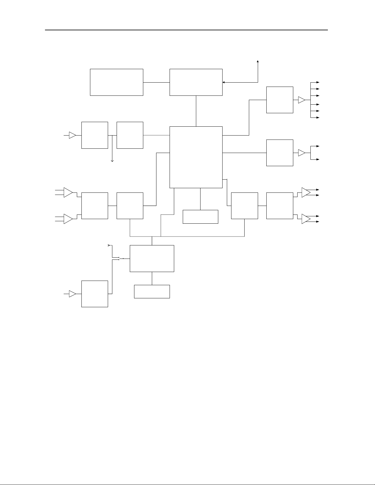
As shown in the block diagram on the next page, two input sources, analog or digital, are
available via local or remote control. The digital input is sample rate converted allowing
for unlocked and/or off frequency digital sources to be used with 24-bit audio precision.
The digital input can also be used for non-audio sources such as AC-3 or Dolby E. In this
case the sample rate converter is by-passed allowing for full 24-bit precision data.
The module locks its audio to a Phase Lock Loop (PLL). The PLL can lock to the digital
input or an external reference as long as the signals are 48 kHz. If no reference is
available, or if desired by the user, the module can lock to an internal crystal.
The module incorporates three outputs; an analog output that can be switched between
delayed and non-delayed audio, an undelayed AES output (two outputs), and a delayed
AES output (six outputs).
Status indicators include indication of a valid external reference, error detection for the
AES input, error indication for any tracking errors, and indication of the bulk delay value.
Control of the module can be from one of the remote Avenue options or from the local
controls located on both the front of the module and on the inside of the module. Local
controls include bulk delay, input selection, analog output mode (delayed or non-delayed),
reference mode, digital reference level, analog input reference level, and analog output
reference level.
The on-board microprocessor communicates with the frame for remote control via the
Avenue System Control module if installed. Module ID (slot location, software version and
board revision) and status information can be monitored by the frame System Control
module and read using the optional interfaces available. Alarms can also be enabled if
desired.
Power is derived from the ± 12 volt frame power. It is regulated to the required voltages
for the module by on-board regulators. The module is fused with resettable fuse devices. If
a fuse opens due to an overcurrent condition, the module will lose power. After pulling the
module, the fuse will reset automatically requiring no replacement fuse.
Model 6040 Tracking Audio Delay
6040-2
Page 3
Model 6040 Tracking Audio Delay
6040-3
6040 Tracking Audio Delay Functional Block Diagram
Remote
Control
Digital IN
buffer
amp
Balanced
Analog IN
amp
LED’s, Switches,
Encoder
AES RX SRC
To PLL
Volume
From Digital
IN
ADC
Audio in 1
Audio in 2
ref. clock
PLL
Microcontroller
DSP
DRAM
Audio Out 1
Audio Out 2
Audio Out 3
DAC Volume
AES TX
delayed
AES TX
undelaye
d
buffer
buffer
amp
Balanced
Analog OUT
amp
Ext. Ref. IN
buffer
AES RX
Crystal
Page 4

Model 6040 Tracking Audio Delay
6040-4
APPLICATIONS
Tracking an All Analog Path
The application shown below illustrates how the Model 6040 Tracking Audio Delay
module can track a video source through a Model 5300 Analog to Digital Video Converter
with the optional 5310 TBC/Frame Synchronizer installed. The 6040 can not only track
the 5310, but can compensate for the video delay in the satellite path.
6040 Tracking an All Analog Path
Satellite
Feed
Composite
Video
5310
TBC/Frame Sync
601
House
Ref. In
Analog
Audio In
AES Ref.
In
5300
ADC
Avenue Comm-link
Ch 1
Ch 2
6040
Tracking Audio Delay
Delayed AES Out
Undelayed AES Out
Ch 1
Ch 2
Analog Out
Delayed or
Undelayed
Page 5
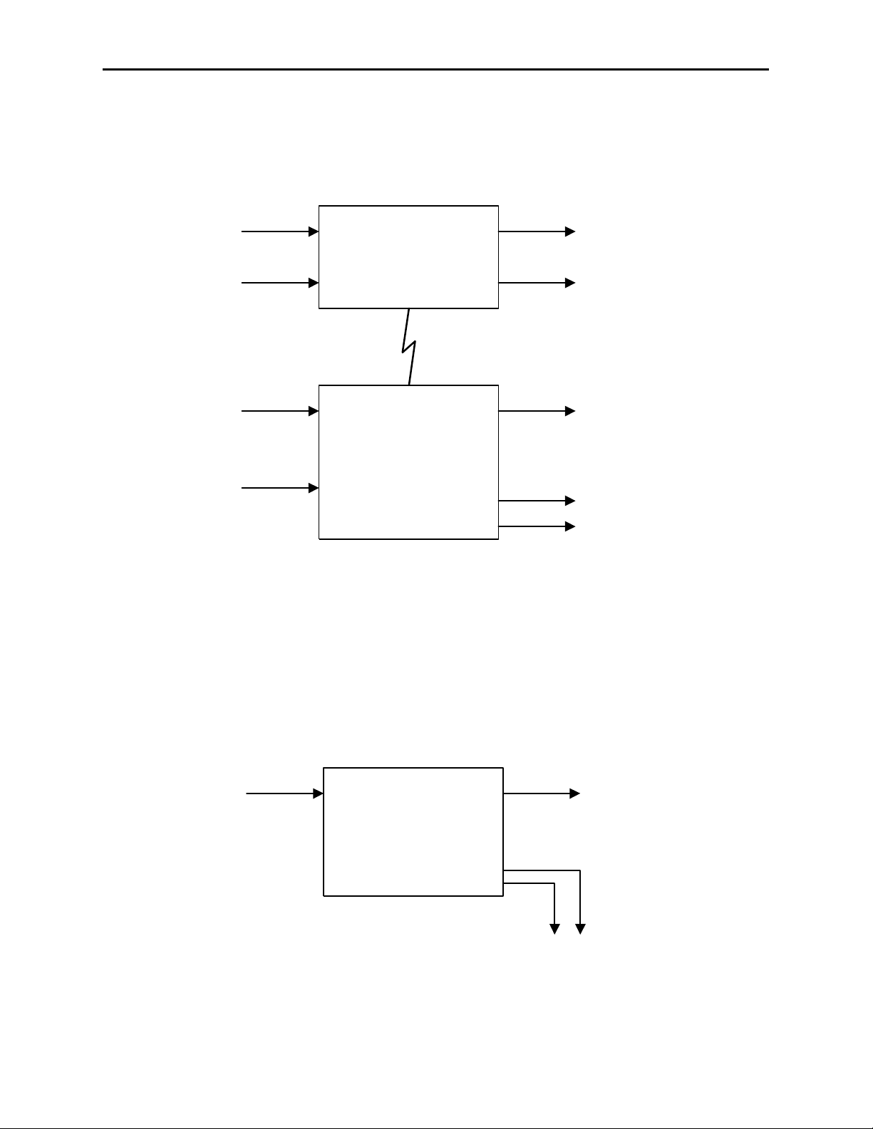
Tracking an All Digital Path
The application below shows how the 6040 can be used in a digital path. Here, the 6040 is
used in conjunction with a Model 5450 Digital Video Frame Synchronizer. Both the 5450
and the 6040 can be used for monitoring.
Delaying Compressed Audio (non-audio) Sources
Another application for the 6040 is delaying compressed audio streams such as AC-3 or
Dolby E. In the illustration shown below, the 6040 locks to the incoming data stream (48
kHz only), delays the data using only the bulk delay value (tracking delay is set to 0), and
mutes the analog outputs. If the non-audio data is not at a 48 kHz sample rate, all of the
outputs will be muted. Note that the 6040 will automatically enter into this mode when it
detects a non-audio source on the Digital input.
Model 6040 Tracking Audio Delay
6040-5
6040 Tracking an All Digital Path
6040 Delaying Compressed Audio Sources
601
House
Ref. In
AES In
5450 Serial Digital
Video Frame
Synchronizer
Avenue Comm-link
601
Composite Video Out to
Monitor
Delayed AES Out
6040
AES Ref.
In
Tracking Audio Delay
Ch 1
Ch 2
Analog Out
to Monitors
AC-3 or
Dolby E
Digital In
Delayed
Out
6040
Tracking Audio Delay
Analog Out
Muted
AC-3 or
Dolby E
Page 6
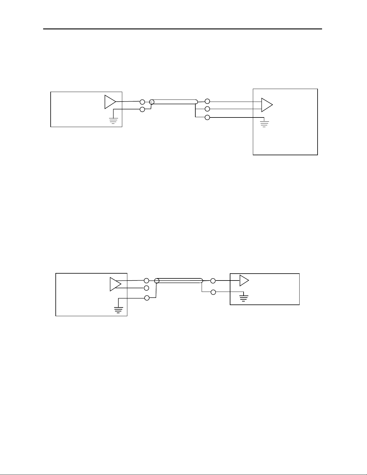
Driving a 6040 Using a Single-ended (unbalanced) Analog Source
The 6040 has balanced transformerless analog inputs. The diagram below shows how to
drive a 6040 using a single-ended (unbalanced) source.
Driving a Singled-ended (unbalanced) Analog Source with a 6040
The 6040 has balanced transformerless analog outputs. This application shows how to
drive external equipment with single-ended (unbalanced) inputs. Note that the minus (-)
side of the balanced output stage is left floating; it should not be connected to ground.
Model 6040 Tracking Audio Delay
6040-6
6040 Driven by Single-Ended (unbalanced) Analog Source
6040 Driving a Single-ended (unbalanced) Source
UNBALANCED
AUDIO OUTPUT
BALANCED
AUDIO INPUT
+
GND
SHIELDED CABLE
_
GND
ANALOG AUDIO SOURCE
6040 ANALOG INPUT
6040 ANALOG OUTPUT
BALANCED
AUDIO OUTPUT
+
_
GND
SHIELDED CABLE
UNBALANCED
AUDIO INPUT
GND
ANALOG AUDIO
DESTINATION
Page 7

Model 6040 Tracking Audio Delay
INSTALLATION
Plug the 6040 module into any one of the ten slots in the frame and install the plastic
overlay provided onto the corresponding group of rear BNC connectors associated with the
module location. Note that the plastic overlay has an optional adhesive backing for
securing it to the frame. Use of the adhesive backing is only necessary if you would like
the location to be permanent and is not recommended if you need to change module
locations. This module may be hot-swapped (inserted or removed) without powering down
or disturbing performance of the other modules in the system.
CABLING
Refer to the 3 RU and 1 RU backplane diagrams of the module on the next page for
cabling instructions. Note that unless stated otherwise, the 1 RU cabling explanations are
identical to those given in the 3 RU diagram.
6040-7
Page 8
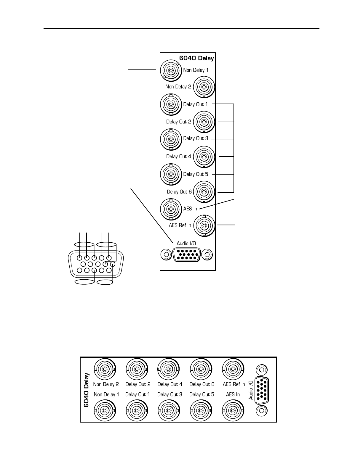
If using an external
reference, connect an
AES reference input to the
AES Ref In BNC.
Connect output destinations
to the Non Delay 1 and 2
BNCs.
Connect analog audio inputs
and outputs to the 15-pin highdensity Audio I/O connector as
shown in the drawing below.
Connect an AES digital
input signal to the AES In
BNC.
Connect output destinations
to the Delay Out 1-6 BNCs
(delayed AES outputs).
3 RU Backplane
1 RU Backplane
Model 6040 Tracking Audio Delay
6040-8
1
6
+
+
+
+
-
-
-
-
11
CH 2
AUDIO IN
AUDIO OUT
CH 1
CH 1
CH 2
6040 Wiring to Frame
15-pin D Male Connector
Wiring Side-Male Plug
Page 9

MODULE CONFIGURATION AND CONTROL
The parameters for each Avenue module must be configured after installation. This can be
done remotely using one of the Avenue remote control options or locally using the module
front panel controls. Each module has a REMOTE/LOCAL switch on the front edge of
the circuit board that must first be set to the control mode you will be using.
The configuration parameter choices for the module will differ between Remote and Local
modes. In Remote mode, the choices are made through software and allow more selections. The 6040 Parameter Table shown on the next page summarizes and compares the
various configuration parameters that can be set remotely or locally and the
default/factory settings.
If you are not using a remote control option, the module parameters must be configured
locally from the front panel encoder and both front panel and internal switches on the
module. Parameters that have no local control will be set to a default value. The Local
switches and internal on-board switches are illustrated in the Front Panel Controls
and Indicators and Internal Jumpers, Switches and Indicators sections following
the 6040 Parameter Table.
Avenue module parameters can be configured and controlled remotely from one or both of
the remote control options, the Avenue Touch Screen or the Avenue PC Application. Once
the module parameters have been set remotely, the information is stored on the module
CPU. This allows the module be moved to a different cell in the frame at your discretion
without losing the stored information. Remote configuration will override whatever the
switch settings are on the front edge of the module.
For setting the parameters remotely using the Avenue PC option, refer to the Avenue PC
Remote Configuration section of this document.
For setting the parameters remotely using the Avenue Touch Screen option, refer to the
Avenue Touch Screen Remote Configuration section of this data pack following the Avenue
PC section.
Model 6040 Tracking Audio Delay
6040-9
Page 10

Model 6040 Tracking Audio Delay
6040 Parameter Table
6040-10
CONTROL LOCAL REMOTE/FACTORY DEFAULT
Bulk Delay Value
Shaft Encoder:
0 – 1000ms
10mS steps
0 – 1000 ms 0 ms
Track Delay (1 – 3) Disabled
Disabled
Connected
No Module
Disabled
Track Frame
(1 – 3)
1 1 – 1000 1
Track Slot #
(1 – 3)
1 1 – 10 1
Bulk Delay Mode
Front Switch:
In
Out
In
Out
Out
Input Source
Front Switch:
In
Out
Analog
Digital
Digital
Analog Output Mode
Front Switch:
Delayed
Undelayed
Delayed
Undelayed
Delayed
Reference Mode
Front Switch:
Auto Select
External Select
Auto Select
External Select
Auto Select
Digital Reference Level
Internal Switches:
– 20 dBFS
– 18 dBFS
– 16 dBFS
– 20 dBFS
– 18 dBFS
– 16 dBFS
– 20 dBFS
Input Mode Stereo
Stereo
2 Channel
Stereo
Analog Input
Reference Level
Internal Switches:
+ 4 dBu
0 dBu
– 8 dBu
+ 4 to –10 dBu + 4 dBu
Output Mode Stereo
Stereo
2 Channel
Stereo
Analog Output
Reference Level
Internal Switches:
+ 4 dBu
0 dBu
– 8 dBu
– 2 dBu
+ 4 to –10 dBu + 4 dBu
Page 11

Remote/Local switch:
Set to the mode you
will be using.
I/P ERR red LED:
With EXT REF switch set as follows:
External Mode
:
ON for no signal at AES digital input.
OFF when valid AES signal present at
input at standard rate (48kHz, 44.1kHz
or 32kHz).
Auto Select Mode
:
OFF when valid AES signal present at
digital input at 48kHz sample rate.
ON if no valid input signal present or
valid AES signal present at rate other
than 48kHz.
Pwr green LED:
Indicates the presence (ON)
or (OFF) of power (+5V).
CPU green LED:
OFF:
A power fault or halted CPU
ON:
A halted CPU
FAST BLINK:
CPU Run error
SLOW BLINK:
System OK. (If SPI control is
active from the main frame
System Control Module, all
Run indicators will be
synchronized.).
TRK ERR red LED:
ON when a Track (-1 - 3) has lost
communication with module it was
tracking. (Tracking delay value for
this module is set to 0.)
OFF when no tracking errors.
EXT REF green LED:
With EXT REF switch
set as follows:
External Mode:
ON for valid AES signal at external
reference input at 48KHz sample rate.
OFF when no signal or signal other
than 48kHz sample rate.
Auto Select Mode
:
ON when module is locked to external
input (valid AES signal at 48kHz
sample rate).
OFF when not locked to external
reference input.
(Note that Auto Select checks AES
digital input first, then external input.)
Bulk Delay green LEDs:
Show bulk delay value.
(200 ms per LED.)
Front Panel Controls and Indicators
Each front edge indicator and switch setting is shown in the diagram below:
Model 6040 Tracking Audio Delay
6040-11
DELAY Adjustment:
Adjusts bulk delay
value in 10 mS steps
(4) IN SEL: Selects input source.
Left: Digital Input (default)
Right: Analog input
(3) BLK I/O:
Bulk delay in or out.
Left: Bulk out (default)
Right: Bulk in.
(2) OUT I/O
: Sets analog delay.
Left: Undelayed (default)
Right: Delayed
(1) EXT REF
: Selects source of
external reference.
Left: Auto Select mode. Module will
scan in order, AES Digital Input,
External Ref Input or Internal clock
for PLL lock source.
Right: External Reference mode.
Module will lock to valid AES 48kHz
signal on external reference. If no
valid signal present, will default to
Internal clock.
Page 12

Internal Switches
When using the 6040 in Local mode, several switches must be set on the circuit board as
detailed in this section.
The following parameters must be set on the circuit board in Local mode:
• Digital Reference (Internal DIP switch S2, positions 1 and 2)
• Analog In (Internal DIP switch S2, positions 3 and 4)
• Analog Out (Internal DIP switch S2, positions 5 and 6)
Refer to the module circuit board layout illustration below to locate each jumper and
switch. The settings for each switch are given in the corresponding tables below.
The 6040 uses an eight position DIP switch, S2, for setting various local levels. The switch
function is shown below:
Model 6040 Tracking Audio Delay
Internal Jumpers and Switches
DIP Switch S2
6040-12
6040 Component Side
S2
D14
J6
J5
J7
J8
Dot on switch represents rocker switch up
1 2 3 4 5 6 7 8
OPEN
Analog In (3-4)
Digital Ref (1-2)
Analog Out (5-6)
Page 13

Digital Ref:
Positions 1 and 2 of Switch S2 are used to set the local Digital Reference level. The
following table shows the possible selections:
Analog In:
Positions 3 and 4 of Switch S2 are used to set the local Analog Input Reference level. The
following table shows the possible selections:
Analog Out:
Positions 5 and 6 of Switch S2 are used to set the local Analog Output Reference level.
The following table shows the possible selections:
5 6
Analog Output
Reference Level
0 0 + 4 dBu
1
0
0 dBu
0 1 – 8 dBu
1 1 – 2 dBu
3 4
Analog Input
Reference Level
0 0 + 4 dBu
1
0
0 dBu
0 1 – 8 dBu
1 1 – 8 dBu
Model 6040 Tracking Audio Delay
1 2 Digital Reference
0 0 – 20 dBFS
1
0
– 18 dBFS
0 1 – 16 dBFS
1 1 – 20 dBFS
6040-13
Page 14
Internal Jumper and Indicators
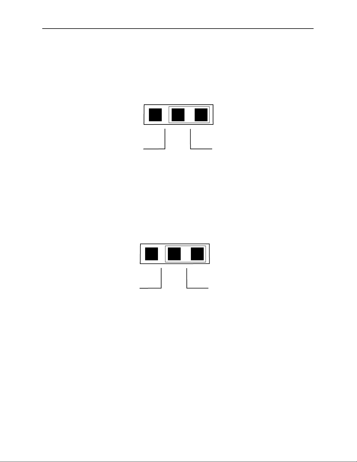
Analog Input Gain Bypass Jumpers:
Jumpers J5 and J6 are set at the factory but can be used to bypass the module's analog
input gain cell if needed for troubleshooting purposes. J5 is used for channel 1 and J6 is
used for channel 2. The following diagram shows the two possible selections
When gain cells are bypassed the reference level is set to a nominal level of +4 dBu. Make
sure the Analog Input jumpers are always set to Enable for normal operation.
Analog Output Jumpers:
Jumpers J7 and J8 are set at the factory but can be used to bypass the modules analog
output gain cells for troubleshooting purposes if needed. J7 is used for channel 2 and J8 is
used for channel 1. The following diagram shows the two possible selections.
When gain cells are bypassed the reference level is set to a nominal level of +4 dBu. Make
sure the Analog Output jumpers are always set to Enable for normal operation.
DSP LED
The 6040 has an internal LED (D14) that is used to indicate the state of the DSP. The two
indicated states are as follows:
• Steady State – If the LED is at a steady state of either ON or OFF then the DSP
is not running. Reset the module to if this has occurred to try to get the DSP
running. If resetting the module will not fix the problem, contact customer support.
• Flashing State – Indicates that the DSP is running normally. Refer to the
Ref/Stat heading in the Avenue PC or Touch Screen sections for more information
regarding the DSP.
Model 6040 Tracking Audio Delay
Analog Input Jumpers J5 and J6
Analog Output Jumpers J7 and J8
6040-14
J5 and J6
Analog Input Jumpers
Front of ModuleRear of Module
Jumper to Bypass
Gain Cell
Jumper to Enable
Gain Cell
J7 and J8
Analog Output Jumpers
Front of ModuleRear of Module
Jumper to Bypass
Gain Cell
Jumper to Enable
Gain Cell
Page 15

Avenue PC Remote Configuration
The Avenue PC remote control menus for this module are illustrated and explained in this
section. Refer to the 6040 Parameter Table shown earlier for a summary of available
parameters that can be set remotely through the menus illustrated. For more information
on using Avenue PC, refer to the Avenue PC Control Application Software data pack that
came with the option.
6040 Avenue PC Menus
In the Delay menu shown below, set the following parameters:
• Bulk Delay – set the delay in pulldown to In to delay the signal path with the
bulk delay value or Out to not delay the signal path.
• Bulk Delay Adj – set the amount of bulk delay from 0 to 1000 mS with the slider
by clicking on the left and right arrows. Select the Default button to enable the
default value. The bulk delay value is given in the box to the right of the slider.
In this menu, the following indicators are available:
• Total Delay – displays the total delay offset in milliseconds in the signal path.
The total value includes bulk delay, Track 1, Track 2 and Track 3 delay values if
enabled.
• Track 1 Delay – displays the amount of delay that is currently being added to the
signal path from the Track 1 module.
• Track 2 Delay – displays the amount of delay that is currently being added to the
signal path from the Track 2 module.
• Track 3 Delay – displays the amount of delay that is currently being added to the
signal path from the Track 3 module.
• Track Error – will display a message indicating tracking errors present.
Model 6040 Tracking Audio Delay
6040-15
Page 16

In the Track 1 menu shown below, set the following parameters:
• Frame # – set frame number (AveNet Number) containing the module you wish to
track. You may have from 1 to 1000 frames. The AveNet frame number is defined
in the frame list on the Avenue PC Main screen.
• Slot # – selects the slot number of the module you wish to track in the frame
chosen above.
In this menu, the following indicators are available:
• Trk 1 En – box displays one of two states when pressed:
• Gray (Tracking 1 is not enabled)
• Gray/Green (Tracking 1 is enabled)
• Status 1 – displays the current state of Tracking 1 as one of the following:
• Disabled (tracking is disabled)
• No Module (Tracking 1 is not communicating with the module selected to
track causing a tracking error)
• Connected (Tracking 1 is communicating with the module selected to track).
• Track 1 Delay – displays the amount of delay that is currently being added to the
signal path from the Track 1 module.
Model 6040 Tracking Audio Delay
6040-16
Page 17

In the Track 2 menu (refer to the Track 1 menu shown on the proceeding page), set the
following parameters:
• Frame # – set frame number (AveNet number) containing the module you wish to
track. You may have form 1 to 1000 frames. The frame Avenet number is defined in
the frame list on the Avenue PC Main screen.
• Slot # – selects the slot number of the module you wish to track in the frame
chosen above.
In this menu, the following indicators are available:
• Trk 2 En – box displays one of two states when pressed:
• Gray (Tracking 2 is not enabled)
• Gray/Green (Tracking 2 is enabled)
• Status 2 – displays the current state of Tracking 2 as one of the following:
• Disabled (tracking is disabled)
• No Module (Tracking 2 is not communicating with the module selected to
track causing a tracking error)
• Connected (Tracking 2 is communicating with the module selected to track)
• Track 2 Delay – displays the amount of delay that is currently being added to the
signal path from the Track 2 module.
In the Track 3 menu (refer to the Track 1 menu shown on the proceeding page), set the
following parameters:
• Frame # – set frame number (AveNet number) containing the module you wish to
track. You may have from 1 to 1000 frames. The frame AveNet number is defined in
the frame list on the Avenue PC Main screen.
• Slot # – selects the slot number of the module you wish to track in the frame
chosen above.
In this menu, the following indicators are available:
• Trk 3 En – box displays one of two states when pressed:
• Gray (Tracking 3 is not enabled)
• Gray/Green (Tracking 3 is enabled)
• Status 3 – displays the current state of Tracking 3 as one of the following:
• Disabled (tracking is disabled)
• No Module (Tracking 3 is not communicating with the module selected to
track causing a tracking error)
• Connected (Tracking 3 is communicating with the module selected to track).
• Track 3 Delay – displays the amount of delay that is currently being added to the
signal path from the Track 3 module.
Model 6040 Tracking Audio Delay
6040-17
Page 18

In the Input menu shown, set the following input parameters:
• In Source – select from two possible input sources:
• Digital (AES input, two channels, are used as the input source)
• Analog (analog inputs are used as the input source)
• In Mode – select from the following modes:
• 2-Channel (analog reference levels for these two channels may be set
independently)
• Stereo (analog reference levels for these two channels track each other)
• Dig. Ref – select from one of three selections as follows:
• -20 dBFS (analog audio reference is set to -20 dBFS in the digital domain,
the most common standard)
• -18 dBFS (analog audio reference is set to -18 dBFS in the digital domain,
the new SMPTE and EBU standard)
• -16 dBFS (analog audio reference is set to -16 dBFS in the digital domain,
the CBC standard)
• A. 1 In Ref – set the analog audio input channel 1 reference level to between
• -10 dBu and +8 dBu with the slider arrows. The selected value will appear
in the box to the right of the slider. Click Default to enable the default value
of +4 dBu.
• A. 2 In Ref – set the analog audio input channel 2 reference level to between
• -10 dBu and +8 dBu with the slider arrows. The selected value will appear
in the box to the right of the slider. Click Default to enable the default value
of +4 dBu.
Model 6040 Tracking Audio Delay
6040-18
Page 19

The following indicator and error boxes are available in the Input menu:
• I/P AES – displays information about the input AES signal that is decoded from
the channel status information as one of the following:
• No audio (signal not present)
• Pro audio (Professional format, stream contains audio data)
• Pro non-audio (Professional format, stream contains non-audio data)
• Cons audio (Consumer format, stream contains audio data)
• Cons non-audio (Consumer format, stream contains non-audio data)
• Sampling Freq – displays the sampling frequency of the input signal pair from
one of the following values:
• 48 kHz
• 44.1 kHz
• 32 kHz
• Non-standard (sampling frequency is not any of the above frequencies)
• I/P Error – one of two colors will display to indicate the AES input status:
• Black (signal is present)
• Red (no valid input present)
• Emph – one of two colors will display to indicate the AES emphasis state:
• Black (no emphasis detected)
• Yellow (50/15 µS emphasis detected. If emphasis is detected, the 6040 will
set the emphasis bits on the AES outputs and apply de-emphasis on the
analog outputs.)
Model 6040 Tracking Audio Delay
6040-19
Page 20

In the Output menu shown, set the following output parameters:
• Analog Out – select from two of the following possible output states:
• Delayed (analog outputs follow the delayed signal path)
• No Delay (analog outputs follow the undelayed signal path)
• Out Mode – select from the following modes:
• 2-Channel (analog reference levels for these two channels may be set
independently)
• Stereo (analog reference levels for these two channels track each other)
• Dig. Ref – select from one of three selections as follows:
• -20 dBFS (analog audio reference is set to -20 dBFS in the digital domain,
the most common standard)
• -18 dBFS (analog audio reference is set to -18 dBFS in the digital domain,
the new SMPTE and EBU standard)
• -16 dBFS (analog audio reference is set to -16 dBFS in the digital domain,
the CBC standard)
• A. 1 Out Ref – set the analog audio output channel 1 reference level to between
• -10 dBu and +8 dBu with the slider arrows. The selected value will appear
in the box to the right of the slider. Click Default to enable the default value
of +4 dBu.
• A. 2 Out Ref – set the analog audio input channel 2 reference level to between
• -10 dBu and +8 dBu with the slider arrows. The selected value will appear
in the box to the right of the slider. Click Default to enable the default value
of +4 dBu.
The following indicator and error boxes are available in the Output menu:
• A. Out Stat – indicates the current state of the analog outputs as one of the
following:
• Normal (analog outputs are operating normally)
• Muted (analog outputs are muted when a non-audio source is being used on
the digital input)
Model 6040 Tracking Audio Delay
6040-20
Page 21

In the Ref/Stat menu shown, set the following output parameters:
• Ref Mode – select from three of the following possible reference modes:
• Auto Sel (module will automatically select the reference from the following
sources, in this order: AES input reference signal if present with sample
rate of 48 kHz, external reference is signal is present with sample rate of 48
kHz, or internal, free run, reference)
• External (module will lock to the external reference unless the signal is
missing or is the wrong sample rate, in which case it will go to the internal
reference)
• Internal (module will use internal reference)
In the Ref/Stat menu shown, the following status indicator boxes are available:
• Ref Status – displays the current reference source the module is using from one of
the following four states:
• AES IN Ref (reference source is AES input)
• Ext. Ref (reference source is external reference input)
• Int. Ref (reference source is internal reference)
• I/P AES – displays information about the input AES signal that is decoded from
the channel status information as one of the following:
• No audio (signal not present)
• Pro audio (Professional format, stream contains audio data
• Pro non-audio (Professional format, stream contains non-audio data)
• Cons audio (Consumer format, stream contains audio data)
• Cons non-audio (Consumer format, stream contains non-audio data)
Model 6040 Tracking Audio Delay
6040-21
Page 22

• Sampling Freq – displays the sampling frequency of the input signal pair from
one of the following values:
• 48 kHz
• 44.1 kHz
• 32 kHz
• Non-std (sampling frequency is not any of the above frequencies)• A.
Out Stat – indicates the current state of the analog outputs as one of the
following:
• Normal (analog outputs are operating normally)
• Muted (analog outputs are muted when a non-audio source is being used on
the digital input)
• Ext In – box indicates the external input status from one of two colors:
• Black (no signal present)
• Green (valid signal present)
• I/P Error – one of two colors will display to indicate the AES input status:
• Black (signal is present)
• Red (no valid input present)
• Emph – one of two colors will display to indicate the AES emphasis state:
• Black (no emphasis detected)
• Yellow (50/15 µS emphasis detected. If emphasis is detected, the 6040 will
set the emphasis bits on the AES outputs and apply de-emphasis on the
analog outputs.)
• DSP – box will display one of the following three colors to indicate the operating
state of the Digital Signal Processor:
• Black (DSP is running but not ready, should only occur at start-up)
• Green (DSP is running normally)
• Red (DSP error)
• PLL – box will indicate one of the following two colors to indicate the operating
state of the Phase Lock Loop:
• Green (PLL is operating correctly)
• Red (flashing indicates PLL error)
Model 6040 Tracking Audio Delay
6040-22
Page 23

Avenue Touch Screen Remote Configuration
Avenue Touch Screen remote control menus for this module are illustrated and explained
below. Refer to the 6040Parameter Table earlier in this section for a summary of
available parameters that can be set remotely through the menus illustrated. For more
information on using the Avenue Touch Screen, refer to the Avenue System Overview.
6040 Avenue Touch Screen Menus
In the Delay menu shown below, set the following parameters:
• Bulk Delay – set the delay in pulldown to In to delay the signal path with the
bulk delay value or Out to not delay the signal path.
• Bulk Delay Adj – set the amount of bulk delay from 0 to 1000 mS with the slider
by clicking on the left and right arrows. Select the Default button to enable the
default value. The bulk delay value is given in the box to the right of the slider.
In this menu, the following indicators are available:
• Total Delay – displays the total delay offset in milliseconds in the signal path. The
total value includes bulk delay, Track 1, Track 2 and Track 3 delay values if
enabled.
• Track 1 Delay – displays the amount of delay that is currently being added to the
signal path from the Track 1 module.
• Track 2 Delay – displays the amount of delay that is currently being added to the
signal path from the Track 2 module.
• Track 3 Delay – displays the amount of delay that is currently being added to the
signal path from the Track 3 module.
• Track Error – will display a message indicating tracking errors present.The
Decode menu below allows you to set the following parameters:
• Comb Filter – select the desired Y/C separation filter. NOTE: The best perfor-
mance for general input video with motion is usually the 3 Line Optimum.
Model 6040 Tracking Audio Delay
6040-23
Page 24

In the Track 1 menu shown below, set the following parameters:
• Frame # – set frame number (AveNet Number) containing the module you wish to
track. You may have from 1 to 1000 frames. The AveNet frame number is defined
in the frame list on the Avenue PC Main screen.
• Slot # – selects the slot number of the module you wish to track in the frame
chosen above.
In this menu, the following indicators are available:
• Trk 1 En – box displays one of two states when pressed:
• Gray (Tracking 1 is not enabled)
• Gray/Green (Tracking 1 is enabled)
• Status 1 – displays the current state of Tracking 1 as one of the following:
• Disabled (tracking is disabled)
• No Module (Tracking 1 is not communicating with the module selected to
track causing a tracking error)
• Connected (Tracking 1 is communicating with the module selected to track).
• Track 1 Delay – displays the amount of delay that is currently being added to the
signal path from the Track 1 module.
Model 6040 Tracking Audio Delay
6040-24
Page 25

In the Track 2 menu (refer to the Track 1 menu shown on the proceeding page), set the
following parameters:
• Frame # – set frame number (AveNet number) containing the module you wish to
track. You may have form 1 to 1000 frames. The frame Avenet number is defined in
the frame list on the Avenue PC Main screen.
• Slot # – selects the slot number of the module you wish to track in the frame
chosen above.
In this menu, the following indicators are available:
• Trk 2 En – box displays one of two states when pressed:
• Gray (Tracking 2 is not enabled)
• Gray/Green (Tracking 2 is enabled)
• Status 2 – displays the current state of Tracking 2 as one of the following:
• Disabled (tracking is disabled)
• No Module (Tracking 2 is not communicating with the module selected to
track causing a tracking error)
• Connected (Tracking 2 is communicating with the module selected to track)
• Track 2 Delay – displays the amount of delay that is currently being added to the
signal path from the Track 2 module.
In the Track 3 menu (refer to the Track 1 menu shown on the proceeding page), set the
following parameters:
• Frame # – set frame number (AveNet number) containing the module you wish to
track. You may have from 1 to 1000 frames. The frame AveNet number is defined in
the frame list on the Avenue PC Main screen.
• Slot # – selects the slot number of the module you wish to track in the frame
chosen above.
In this menu, the following indicators are available:
• Trk 3 En – box displays one of two states when pressed:
• Gray (Tracking 3 is not enabled)
• Gray/Green (Tracking 3 is enabled)
• Status 3 – displays the current state of Tracking 3 as one of the following:
• Disabled (tracking is disabled)
• No Module (Tracking 3 is not communicating with the module selected to
track causing a tracking error)
• Connected (Tracking 3 is communicating with the module selected to track).
• Track 3 Delay – displays the amount of delay that is currently being added to the
signal path from the Track 3 module.
Model 6040 Tracking Audio Delay
6040-25
Page 26

In the Input menu shown, set the following input parameters:
• In Source – select from two possible input sources:
• Digital (AES input, two channels, are used as the input source)
• Analog (analog inputs are used as the input source)
• In Mode – select from the following modes:
• 2-Channel (analog reference levels for these two channels may be set
independently)
• Stereo (analog reference levels for these two channels track each other)
• Dig. Ref – select from one of three selections as follows:
• -20 dBFS (analog audio reference is set to -20 dBFS in the digital domain,
the most common standard)
• -18 dBFS (analog audio reference is set to -18 dBFS in the digital domain,
the new SMPTE and EBU standard)
• -16 dBFS (analog audio reference is set to -16 dBFS in the digital domain,
the CBC standard)
• A. 1 In Ref – set the analog audio input channel 1 reference level to between
• -10 dBu and +8 dBu with the slider arrows. The selected value will appear
in the box to the right of the slider. Click Default to enable the default value
of +4 dBu.
• A. 2 In Ref – set the analog audio input channel 2 reference level to between
• -10 dBu and +8 dBu with the slider arrows. The selected value will appear
in the box to the right of the slider. Click Default to enable the default value
of +4 dBu.
6040-26
Model 6040 Tracking Audio Delay
Page 27

The following indicator and error boxes are available in the Input menu:
• I/P AES – displays information about the input AES signal that is decoded from
the channel status information as one of the following:
• No audio (signal not present)
• Pro audio (Professional format, stream contains audio data)
• Pro non-audio (Professional format, stream contains non-audio data)
• Cons audio (Consumer format, stream contains audio data)
• Cons non-audio (Consumer format, stream contains non-audio data)
• Sampling Freq – displays the sampling frequency of the input signal pair from
one of the following values:
• 48 kHz
• 44.1 kHz
• 32 kHz
• Non-standard (sampling frequency is not any of the above frequencies)
• I/P Error – one of two colors will display to indicate the AES input status:
• Black (signal is present)
• Red (no valid input present)
• Emph – one of two colors will display to indicate the AES emphasis state:
• Black (no emphasis detected)
• Yellow (50/15 µS emphasis detected. If emphasis is detected, the 6040 will
set the emphasis bits on the AES outputs and apply de-emphasis on the
analog outputs.)
Model 6040 Tracking Audio Delay
6040-27
Page 28

In the Output menu shown, set the following output parameters:
• Analog Out – select from two of the following possible output states:
• Delayed (analog outputs follow the delayed signal path)
• No Delay (analog outputs follow the undelayed signal path)
• Out Mode – select from the following modes:
• 2-Channel (analog reference levels for these two channels may be set
independently)
• Stereo (analog reference levels for these two channels track each other)
• Dig. Ref – select from one of three selections as follows:
• -20 dBFS (analog audio reference is set to -20 dBFS in the digital domain,
the most common standard)
• -18 dBFS (analog audio reference is set to -18 dBFS in the digital domain,
the new SMPTE and EBU standard)
• -16 dBFS (analog audio reference is set to -16 dBFS in the digital domain,
the CBC standard)
• A. 1 Out Ref – set the analog audio output channel 1 reference level to between
• -10 dBu and +8 dBu with the slider arrows. The selected value will appear
in the box to the right of the slider. Click Default to enable the default value
of +4 dBu.
• A. 2 Out Ref – set the analog audio input channel 2 reference level to between
• -10 dBu and +8 dBu with the slider arrows. The selected value will appear
in the box to the right of the slider. Click Default to enable the default value
of +4 dBu.
The following indicator and error boxes are available in the Output menu:
• A. Out Stat – indicates the current state of the analog outputs as one of the
following:
• Normal (analog outputs are operating normally)
• Muted (analog outputs are muted when a non-audio source is being used on
the digital input)
Model 6040 Tracking Audio Delay
6040-28
Page 29

In the Ref/Stat menu shown, set the following output parameters:
• Ref Mode – select from three of the following possible reference modes:
• Auto Sel (module will automatically select the reference from the following
sources, in this order: AES input reference signal if present with sample
rate of 48 kHz, external reference is signal is present with sample rate of 48
kHz, or internal, free run, reference)
• External (module will lock to the external reference unless the signal is
missing or is the wrong sample rate, in which case it will go to the internal
reference)
• Internal (module will use internal reference)
In the Ref/Stat menu shown, the following status indicator boxes are available:
• Ref Status – displays the current reference source the module is using from one of
the following four states:
• AES IN Ref (reference source is AES input)
• Ext. Ref (reference source is external reference input)
• Int. Ref (reference source is internal reference)
• I/P AES – displays information about the input AES signal that is decoded from
the channel status information as one of the following:
• No audio (signal not present)
• Pro audio (Professional format, stream contains audio data
• Pro non-audio (Professional format, stream contains non-audio data)
• Cons audio (Consumer format, stream contains audio data)
• Cons non-audio (Consumer format, stream contains non-audio data)
Model 6040 Tracking Audio Delay
6040-29
Page 30

• Sampling Freq – displays the sampling frequency of the input signal pair from
one of the following values:
• 48 kHz
• 44.1 kHz
• 32 kHz
• Non-std (sampling frequency is not any of the above frequencies)• A.
Out Stat – indicates the current state of the analog outputs as one of the
following:
• Normal (analog outputs are operating normally)
• Muted (analog outputs are muted when a non-audio source is being used on
the digital input)
• Ext In – box indicates the external input status from one of two colors:
• Black (no signal present)
• Green (valid signal present)
• I/P Error – one of two colors will display to indicate the AES input status:
• Black (signal is present)
• Red (no valid input present)
• Emph – one of two colors will display to indicate the AES emphasis state:
• Black (no emphasis detected)
• Yellow (50/15 µS emphasis detected. If emphasis is detected, the 6040 will
set the emphasis bits on the AES outputs and apply de-emphasis on the
analog outputs.)
• DSP – box will display one of the following three colors to indicate the operating
state of the Digital Signal Processor:
• Black (DSP is running but not ready, should only occur at start-up)
• Green (DSP is running normally)
• Red (DSP error)
• PLL – box will indicate one of the following two colors to indicate the operating
state of the Phase Lock Loop:
• Green (PLL is operating correctly)
• Red (flashing indicates PLL error)
Model 6040 Tracking Audio Delay
6040-30
Page 31

TROUBLESHOOTING
To aid in troubleshooting, signal reference levels and presence, power and CPU status can
be easily monitored from the front panel of this module using the indicators explained in
the previous section.
If using the Remote mode, the following status items can be monitored using the Avenue
Touch Screen Control Panel or PC Application:
• Tracking errors
• Reference status
• AES input error
• Emphasis flag set on AES input
• AES input format and content
• DSP status
• PLL status
• Analog Output status
• Power status
• Slot ID, Software Version and Board Revision
Refer to the overall troubleshooting tips given below for the 6040 module:
No status lights are lit on front panel:
• Check that frame power is present (green LED{s} on frame power supplies).
• Check that module is firmly seated in frame. Try removing it and plugging
it in again.
Can't control module:
• Check status of CPU Run LED. Should be blinking slowly and in unison
with other modules if System Control module is present. If not, try removing
it and plugging it in again.
• System Control module may not be working properly if installed.
No audio delay and/or cannot control audio:
• Check for DSP status. If status is not green, try removing module and
plugging it in again.
Digital audio is muted:
• Check digital audio status. If audio source is non-audio at a sample rate
other than 48kHz the module will mute the audio. Try a different source.
• Check cabling to input module.
• Check for a valid AES signal input.
No tracking delay values:
• Check to make sure tracking is enabled and communicating with the
selected module.
• Check to make sure the module has a valid audio source (no tracking with
non-audio sources).
No analog signal out of module:
• Check cabling from the output of module.
• Check for valid AES signal input or analog input source.
• If using the AES input, check to make sure the AES signal is a audio source.
Model 6040 Tracking Audio Delay
6040-31
Page 32

No analog input:
• Check cabling to the module.
• Check to make sure the analog input is selected as an input source.
You may also refer to the technical support section of the Ensemble web site for the latest
information on your equipment at the URL below:
http://www
.ensembledesigns.com/support
SOFTWARE UPDATING
Software upgrades for each module can be downloaded remotely if the optional System
Control module is installed. These can be downloaded onto your PC and then Avenue PC
will distribute the update to the individual module. (Refer to the Avenue PC documentation for more information) Periodically updates will be posted on our web site. If you do
not have the required System Control Module and Avenue PC, modules can be sent back
to the factory for software upgrades.
Model 6040 Tracking Audio Delay
6040-32
Page 33

6040-33
Model 6040 Tracking Audio Delay
WARRANTYAND FACTORY SERVICE
Warranty
This Module is covered by a five year limited warranty, as stated in the main Preface of
this manual. If you require service (under warranty or not), please contact Ensemble
Designs and ask for customer service before you return the unit. This will allow the
service technician to provide any other suggestions for identifying the problem and
recommend possible solutions.
Factory Service
If you return equipment for repair, please get a Return Material Authorization Number
(RMA) from the factory first.
Ship the product and a written description of the problem to:
Ensemble Designs, Inc.
Attention: Customer Service RMA #####
870 Gold Flat Rd.
Nevada City, CA. 95959 USA
(530) 478-1830
Fax: (530) 478-1832
service@endes.com
http://www.ensembledesigns.com
Be sure to put your RMA number on the outside of the box.
Page 34

6040-34
SPECIFICATIONS
6040 Tracking Audio Delay
Inputs:
AES Input: 1 Volt p-p, terminated in 75 ohms
Sample Rate: 32 kHz - 96 kHz
AES Reference: 1 Volt p-p, terminated in 75 ohms
Sample Rate: 48 kHz, ± 3 Hz
Analog Input Z: > 15 k ohms, balanced, transformerless
CMRR: > 60 dB, 20Hz to 10kHz
Input gain range: –10 dBu to +8 dBu for –20, –18, or –16 dBFS input
Outputs:
AES Outputs: 1 Volt p-p, 75 ohms source terminated
Sample Rate: 48 kHz
Analog Output Z: 30 ohms, balanced, transformerless
Output Level: – 10 dBu to +8 dBu for -20, -18 or -16 dBFS input
Max Output Level: @ 86 dB THD+N
+24 dBu (bridging load), +22 dBu (600 ohm load)
Frequency Response: +0/-0.2 dB, 20 Hz - 20 kHz
Crosstalk: < – 84 dB, 20 Hz - 20 kHz
Dynamic Range: 95 dB
Delay:
Bulk Delay: 0 to 1 second, 10 mS steps
Tracking Delay: Up to 3 modules at one time,
maximum delay per module 100 mS
Max Audio Delay: 1.3 seconds per channel
Delay Response Time: 6 seconds for both bulk and tracking values,
0 for non-audio sources
General Specifications
Temperature Range: 0 to 40 degrees C ambient (all specs met)
Relative Humidity: 0 to 95% noncondensing
Altitude: 0 to 10,000 ft
Due to ongoing product development, all specifications subject to change.
Model 6040 Tracking Audio Delay
 Loading...