

Page 1
This data pack provides detailed installation, configuration and operation information for
the Model 6020 Four Channel 20-bit Audio Digital to Analog Converter (DAC)
module as part of the Avenue Signal Integration System.
The module information in this data pack is organized into the following sections:
• Module Overview
• Applications
• Installation
• Cabling
• Module Configuration and Control
°
Front Panel Controls and Indicators
°
Avenue PC Remote Control
°
Avenue Touch Screen Remote Control
• Troubleshooting
• Software Updating
• Warranty and Factory Service
• Specifications
6020-1
Model 6020
Four Channel
20-bit Audio DAC
Data Pack
Revision 3.1 SW v1.0.0
Page 2

MODULE OVERVIEW
The 6020 Four Channel 20-bit Digital to Analog Converter (DAC) converts two AES digital
audio streams to four channels of analog audio. Digital to analog conversion is performed
with 20-bit precision.
As shown in the block diagram below, two AES audio inputs from BNCs on the backplane
enter the module and pass through AES receiver circuitry to the digital to analog converters. A gain adjustment is provided for the analog output levels. The buffered audio is then
fed to the output to a 15-pin high density connector. Unbalanced monitor outputs are
provided on BNC connectors.
Status indicators include error detection for noting presence of valid AES input signals as
well as indication that emphasis flags have been set on either AES input. Appropriate deemphasis is applied automatically when a flag is set.
Control of the module can be from one of the remote Avenue options or from the local
controls on the front of the module. The gain of the analog output stages can be adjusted
remotely or locally. The on-board microprocessor communicates with the frame for remote
control via the Avenue System Control module if installed. Module ID information (slot
location, software version and board revision) and status information can be monitored by
the frame System Control module and read using the optional interfaces available. Alarms
can also be enabled if desired.
Power is derived from the ± 12 volt frame power. It is regulated to the required voltages
for the module by on-board regulators. The module is fused with resettable fuse devices. If
the fuse opens due to an overcurrent condition, the module will lose power. After pulling
the module, the fuse will reset automatically requiring no replacement fuse.
Model 6020 Four Channel 20-bit Audio DAC
6020 Four Channel 20-bit Audio DAC Functional Block Diagram
6020-2
Remote
Control
Balanced
Analog
Outputs
Balanced
Analog
Outputs
AES
Input
AES
Input
AES
RX
AES
RX
DAC
DAC
Microcontroller
Level
Control
Gain
Adj.
Gain
Adj.
Gain
Adj.
Gain
Adj.
Status
Indicators
Page 3

APPLICATIONS
In the application illustrated below, a 6020 module is used to convert two 2-channel AES
signals to analog to feed the audio inputs of an analog VTR. Unbalanced monitor outputs
are used to drive a local audio monitoring system.
Even though it is a four channel device, the 6020 utilizes two separate 2-channel D/A converters. In the application shown below, a 6020 module is used to convert two independent
2-channel AES signals to analog to feed the audio inputs of two independent 2-track
analog audio tape recorders. Care should be exercised when connecting the audio outputs
of the 6020 to ensure that one machine is connected to outputs 1 and 2 and the other
machine to outputs 3 and 4. This will ensure that the pairing of the AES input signals will
be preserved at the analog inputs of the two tape machines.
Model 6020 Four Channel 20-bit Audio DAC
6020-3
6020 Feeding an Analog VTR
6030 Converting Two Independent 2-Channel AES Signals
AUDIO MONITORS
BALANCED AUDIO INPUTS
AES IN
CH 1/2
AES IN
CH 3/4
UNBALANCED OUTPUTS
CH 1
CH 2
CH 3
CH 4
6020 AUDIO DAC
ANALOG VTR
AUDIO TAPE RECORDER #1
AES IN
#1
AES IN
#2
AUDIO OUTPUTS
CH 1
CH 2
CH 3
CH 4
CH 1/LEFT
CH 2/RIGHT
AUDIO INPUTS
CH 3/LEFT
6020 AUDIO DAC
CH 4/RIGHT
AUDIO TAPE RECORDER #2
Page 4
In the application shown below, a 6020 module is used to convert two AES audio outputs
of a digital VTR to analog in order to feed an analog audio routing switcher.
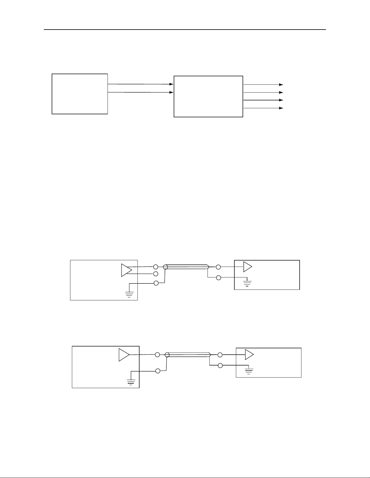
The 6020 has balanced transformerless outputs. This application shows how to drive
external equipment with single-ended (unbalanced) inputs. Note that the minus (-) side of
the balanced output stage is left floating; it should not be connected to ground. In addition
to its four balanced line level outputs, the 6020 has four unbalanced outputs. These
outputs, available on BNC connectors, are suitable for driving monitor amplifiers or other
similar equipment as shown in the first application on the preceding page.
Model 6020 Four Channel 20-bit Audio DAC
6020-4
6020 Converting Digital VTR Outputs to Feed Analog Routing Switcher
6020 Driving Single-Ended Inputs
AUDIO OUTPUTS
AES OUT CH 1/2
AES OUT CH 3/4
CH 1
CH 2
CH 3
CH 4
ANALOG AUDIO
TO FACILITY
ROUTING
SIWTHCER
DIGITAL VTR
6020 AUDIO DAC
BALANCED
AUDIO OUTPUT
(1 OF 4) UNBALANCED AUDIO INPUT
+
_
GND
6020 AUDIO DAC
SHIELDED CABLE
GND
ANALOG AUDIO
DESTINATION
6020 AUDIO DAC
UNBALANCED
AUDIO OUTPUT
(1 OF 4)
SHIELDED CABLE
GND
UNBALANCED AUDIO INPUT
GND
ANALOG AUDIO
DESTINATION
Page 5
Model 6020 Four Channel 20-bit Audio DAC
6020-5
INSTALLATION
Plug the 6020 module into any one of the ten slots in the frame and install the plastic
overlay provided onto the corresponding group of rear BNC connectors associated with the
module location. Note that the plastic overlay has an optional adhesive backing for
securing it to the frame. Use of the adhesive backing is only necessary if you would like
the location to be permanent and is not recommended if you need to change module
locations. This module may be hot-swapped (inserted or removed) without powering down
or disturbing performance of the other modules in the system.
CABLING
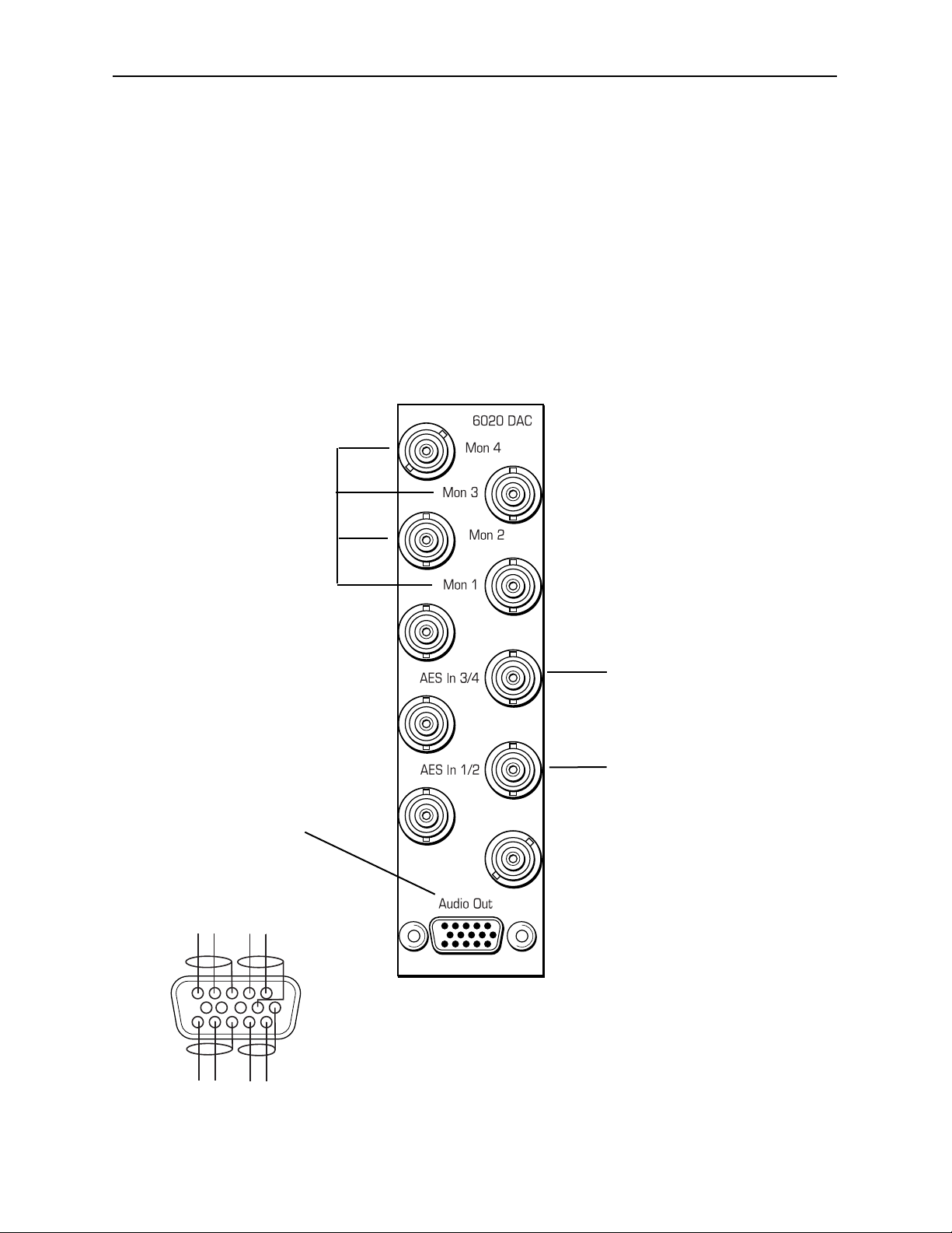
Refer to the backplane diagram of the module below for cabling instructions.
Connect an AES
input signal to the
AES In 1/2 BNC.
Connect the 15-pin
high-density Audio Out
connector to an analog
audio destination.
Refer to the pinout
diagram below.
Connect an AES
input signal to the
AES In 3/4 BNC.
Connect Mon 1-4
BNCs to to singleended analog
monitor outputs.
6020 Wiring to Frame
15-pin D Male Connector
CH 2
+
+
CH 4
Wiring Side-Male Plug
---
CH 1
-
CH 3
+
1
6
11
+
Page 6

MODULE CONFIGURATION AND CONTROL
The parameters for each Avenue module must be configured after installation. This can be
done remotely using one of the Avenue remote control options or locally using the module
front panel controls. Each module has a REMOTE/LOCAL switch on the front edge of
the circuit board which must first be set to the control mode you will be using.
The configuration parameter choices for the module will differ between Remote and
Local modes. In Remote mode, the choices are made through software and allow more
selections. The 6020 Parameter Table on the following page summarizes and compares
the various configuration parameters that can be set remotely or locally and the
default/factory settings.
If you are not using an remote control option, the module parameters must be configured
from the front panel switches. Parameters that have no front panel control will be set to a
default value. The Local switches are illustrated in the Front Panel Controls and
Indicators section following the 6020 Parameter Table.
Avenue module parameters can be configured and controlled remotely from one or both of
the remote control options, the Avenue Touch Screen or the Avenue PC Application. Once
the module parameters have been set remotely, the information is stored on the module
CPU. This allows the module be moved to a different cell in the frame at your discretion
without losing the stored information. Remote configuration will override whatever the
switch settings are on the front edge of the module.
For setting the parameters remotely using the Avenue PC option, refer to the Avenue PC
Remote Configuration section of this document.
For setting the parameters remotely using the Avenue Touch Screen option, refer to the
Avenue Touch Screen Remote Configuration section of this data pack following
Avenue PC.
Model 6020 Four Channel 20-bit Audio DAC
6020-6
Page 7

Model 6020 Four Channel 20-bit Audio DAC
6020 Parameter Table
6020-7
CONTROL
Ch 1/2 Mode
Ch 3/4 Mode
Ch 1/2 Emph Mode
Ch 3/4 Emph Mode
CH 1-4 Digital Ref
Ch 1-4 Analog Ref
LOCAL
No Adjustment
No Adjustment
No Adjustment
Shaft Encoder:
-10dBu to +8dBu
REMOTE
2-Channel
Stereo
Quad Tracking
Off
On
Auto
-20 dBFS
-18 dBFS
-16DBFS
(Ch 1-4 Quad Tracking,
Ch 1/2 and/or 3/4 stereo pair or
individual channel adjustment)
-10dBu to +8dBu
(Ch 1-4 Quad Tracking,
Ch 1/2 and/or 3/4 stereo pair or
individual channel adjustment)
DEFAULT VALUE
Quad Tracking
Auto
N/A
N/A
Page 8

Model 6020 Four Channel 20-bit Audio DAC
Front Panel Controls and Indicators
Each front edge indicator and switch setting is explained in the diagram below:
6020-8
Remote/Local switch:
Selects local or
remote control.
Pwr green LED:
Indicates the presence (ON)
or absence (OFF) of power.
CPU green LED:
OFF:
A power fault or halted CPU
ON:
A halted CPU
FAST BLINK:
CPU Run error
SLOW BLINK:
System OK. (If SPI control is
active from the main frame
System Control Module, all
Run indicators will be syn-
chronized.).
Err 1/2 and 3/4 red LEDs:
Blinking indicates no signal
present or other major errors.
On indicates signal present
with minor errors.
OFF AES signal inputs OK.
GAIN Adjustment:
Adjusts all four analog
outputs equally.
Emp 1/2 and 3/4 yellow LEDs:
ON indicates emphasis is being
corrected.
Blinking indicates emphasis is not
being corrected or incorrect deemphasis has been forced manually.
Off indicates no emphasis is
detected on the input signal pair.
Page 9

Avenue PC Remote Configuration
The Avenue PC remote control menus for this module are illustrated and explained in this
section. Refer to the 6020 Parameter Table shown earlier for a summary of available
parameters that can be set remotely through the menus illustrated. For more information
on using Avenue PC, refer to the Avenue PC Control Application Software data pack that
came with the option.
6020 Avenue PC Menus
The menus for the 6020 Audio DAC in the Avenue PC application allow you to set the
parameters for four channels of audio on this module. You may choose from three
operating modes, 2-Channel, Stereo or Quad Tracking.
You may set all four channels to 2-Channel mode, where each of the four audio channels
will be independent of each other. Adjustments may be made to each channel individually
and will not affect the other channels. Menu selections are provided for each channel as
shown in the following section.
You may set the four channels to Stereo mode, where Channels 1 and 2 and Channels 3
and 4 are stereo pairs. Adjustments made in the menus to one channel in the pair will
change the other channel. Channel 1 and 2 can be set to be independent (2-Channel)
while Channel 3 and 4 can be set to be a stereo pair if desired (or vice versa).
All four channels can be set to Quad Tracking where all channels will track together. If
parameters are changed in one channel, the other channels will track the change.
Selecting Quad Tracking in any one of the menus will change all channels to quad
tracking mode. A Quad Menu has been provided to allow easier adjusting and monitoring of all four channels together.
Model 6020 Four Channel 20-bit Audio DAC
6020-9
Page 10
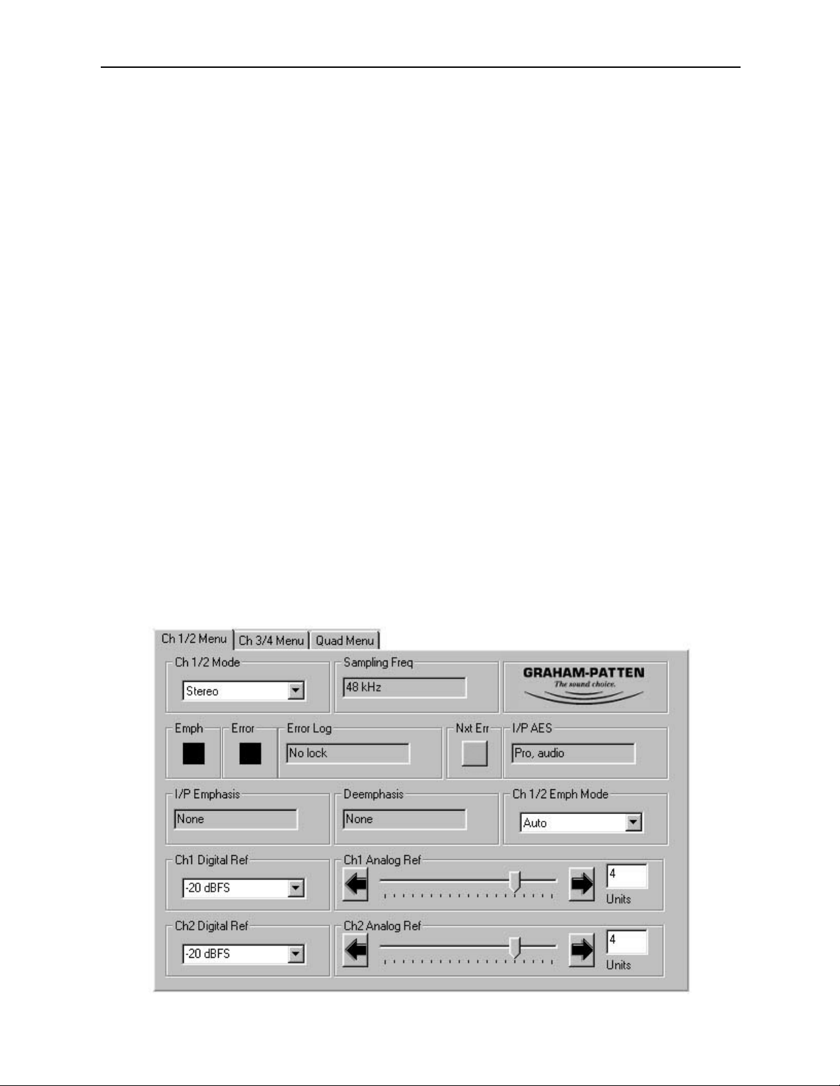
In the Ch 1/2 Menu shown below, set the following parameters:
• Ch 1/2 Mode - set the operating modes for Channels 1 and 2.
Choose from 2-Channel (Ch 1 and 2 will be independent), Stereo (Ch 1/2 will be a
stereo pair) or Quad Tracking (Ch 1-4 will track together.) Note that if you have
set Ch 3/4 in the next menu to Quad Tracking or the Quad On function is
enabled on the Quad Menu, this selection will default to Quad Tracking.
• Ch 1 Digital Ref - set the Digital Audio Reference level to match the studio
reference (-20dBFS, -18dBFS or -16dBFS) for channel 1 (in 2-Channel mode),
Ch 1/2 if in Stereo mode or all four channels together if in Quad Tracking mode.
• Ch 1 Analog Ref - use slider to set the Analog Audio Reference level from -10dBu
to +8dBu (in 0.5dBu steps) for channel 1 only (in 2-Channel mode), Ch 1/2 if in
Stereo mode or all four channels if in Quad Tracking mode.
• Ch 2 Dig Ref - when Ch 1/2 Mode is set to 2-Channel, this will adjust Channel 2
Digital Reference level only. If Ch 1/2 Mode is set to Stereo, adjustment will
affect the stereo pair, or if set to Quad Tracking, adjustment will affect all
channels.
• Ch 2 Analog Ref - when Ch 1/2 Mode is set to 2-Channel, this slider will adjust
Channel 2 Analog Reference level only. If Ch 1/2 Mode is set to Stereo, adjust-
ment will affect the stereo pair, or if set to Quad Tracking, adjustment will affect
all channels.
• Ch 1/2 Emph - sets the emphasis correction mode for these two channels. Off
disables the emphasis correction. On applies 50/15µS deemphasis to the two
channels when the sampling frequency is standard. (Note that deemphasis will not
be applied where frequencies are non-standard.) Auto applies 50/15µS deemphasis
as necessary depending on the AES input emphasis status and sampling frequency.
(Note that deemphasis will not be applied when the channel status indicates the
use of CCITT J.17 emphasis.)
In this menu, the following indicators are available:
6020-10
Model 6020 Four Channel 20-bit Audio DAC
Page 11

• Emph - the color of this box indicates the status of emphasis on the digital input
signal pair as follows:
Yellow indicates emphasis is present on the input and is being corrected.
Yellow/Gray (blink) indicates input emphasis is not being corrected or
incorrect deemphasis has been forced manually.
Black indicates no emphasis is detected on the input signal pair.
• Error - will indicate the presence of errors on the input signal pair as follows:
Red indicates minor errors exist on the input signal pair and have been logged.
Red/Gray (Blink) indicates major errors exist on the input signal pair and
have been logged.
Black indicates no errors exist on the input signal pair.
• Nxt Err - a left mouse-click on this box will clear the currently displayed error in
the Error Log (explained below). It will then display the next highest priority
error logged if it is present.
• Sampling Freq - displays the sampling frequency of the input signal pair. The
following sampling frequencies will be displayed:
48kHz
44.1kHz
44.056kHz
32kHz
Non-standard indicates the sampling frequency is not within 4% of any of the
above frequencies.
• Error Log - displays the most important error detected in the AES input signal
pair that occurred since the log was last cleared. Seven error messages, in order of
decreasing importance, may be displayed as follows. The first three of these are
treated as major errors.
No lock
- input PLL is unable to lock to the AES input signal.
Bi-phase coding
- a bi-phase coding error in the AES input signal is detected.
Parity
- a parity error has been detected.
CRC
- the CRC data in the AES input signal did not match the locally calculated
CRC (professional format only).
Confidence
- the input signal eye opening has fallen below AES standard limits.
Invalid Error
- the validity bit in the AES input signal has been set.
No error
- no errors have been detected since the log was last cleared.
6020-11
Model 6020 Four Channel 20-bit Audio DAC
Page 12

• I/P AES - displays information about the input AES signal that is decoded from the
channel status information as follows:
Blank
- Professional format with CRC errors.
Pro
Audio - Professional format where stream contains audio data.
Pro non-audio
- Professional format where stream contains non-audio data.
Cons audio
- Consumer format where stream contains non-copyright audio data.
Cons non-audio
- Consumer format where stream contains non-audio data.
Cons copy OK
- Consumer format where stream contains original copyright
material that may be copied once.
Cons copy inh
- Consumer format where stream contains a copy of copyright
material that may not be copied again.
• I/P Emphasis - displays emphasis data decoded for the input AES signal as
follows:
None
- indicates input signal has no emphasis.
Not indicated
- emphasis status of the AES input audio is not indicated (profes-
sional format only).
50/15
µS - emphasis using these time constants was applied to the input AES
signal.
CCITT J.17
- emphasis conforming to this standard was applied to the input
AES signal (professional format only).
• Deemphasis - displays any deemphasis being applied to the signal by the 6020
module as follows:
None
- no deemphasis is being applied.
50/15
µS - deemphasis using these time constants is being applied.
Model 6020 Four Channel 20-bit Audio DAC
6020-12
Page 13

In the Ch 3/4 Menu shown below, set the following parameters:
• Ch 3/4 Mode - set the operating modes for Channels 3 and 4.
Choose from 2-Channel (Ch 3 and 4 will be independent), Stereo (Ch 3/4 will be
a stereo pair) or Quad Tracking (Ch 1-4 will track together). Note that if you
have set Ch 1/2 to Quad Tracking or the Quad On function is enabled on the
Quad Menu, this selection will default to Quad Tracking.
• Ch 3 Digital Ref - sets the Digital Audio Reference level for channel 3 (in
2-Channel mode). If Ch 3/4 Mode is set to Stereo, adjustment will affect the
stereo pair, or if set to Quad Tracking, adjustment will affect all channels.
• Ch 3 Analog Ref - sets the Analog Audio Reference level from -10dBu to +8dBu
(in 0.5dBu steps) for channel 3 only (in 2-Channel mode). If Ch 3/4 Mode is set
to Stereo, adjustment will affect the stereo pair, or if set to Quad Tracking,
adjustment will affect all channels.
• Ch 4 Dig Ref - When Ch 3/4 Mode is set to 2-Channel, this will adjust Channel
4 Digital Reference level only. If Ch 3/4 Mode is set to Stereo, adjustment will
affect the stereo pair, or if set to Quad Tracking, adjustment will affect all
channels.
• Ch 4 Analog Ref - When Ch 3/4 Mode is set to 2-Channel, this will adjust
Channel 4 Analog Reference level only. If Ch 3/4 Mode is set to Stereo, adjust-
ment will affect the stereo pair, or if set to Quad Tracking, adjustment will affect
all channels.
• Ch 3/4 Emph - sets the emphasis correction mode for these two channels. Off
disables the emphasis correction. On applies 50/15µS deemphasis to the two
channels when the sampling frequency is standard. (Note that deemphasis will not
be applied where frequencies are non-standard.) Auto applies 50/15µS deemphasis
as necessary depending on the AES input emphasis status and sampling
frequency. (Note that deemphasis will not be applied when the channel status
indicates the use of CCITT J.17 emphasis.)
6020-13
Model 6020 Four Channel 20-bit Audio DAC
Page 14

Refer to the Emph, Error, Nxt Error, Sampling Freq, Error Log, I/P AES, I/P
Emphasis, and Deemphasis indicator explanations for the Ch1/2 menu shown earlier.
The Quad Menu shown below has been provided to allow adjusting and monitoring all
four channels at the same time when in Quad Tracking mode. Set the parameters as
follows:
• Channel Mode - Click in the Quad On box to enable quad tracking simultaneous-
ly for all four channels. Note that Quad Tracking can also be enabled in any of
the previous Channel Mode menus.
• Emphasis Mode - set the emphasis mode for all four channels.
• Digital Ref - set all four channels for the Digital Reference level to match your
studio reference.
• Analog Ref - adjust the Analog Reference level of all four channels to
-10dBu to +8dBu (in 0.5dBu steps).
NOTE: Digital and Analog Ref settings and Emphasis Mode above will only be
active when Quad On is checked.
The following indicators are available in the menu below:
• Err 1/2 and Err 3/4 - indicates the presence of errors on the input signal pairs as
described previously in the Ch 1/2 Menu indicator descriptions.
• Emph (2 boxes) - each box shows the status of emphasis for the channel pair corresponding to the Error box above it.
Model 6020 Four Channel 20-bit Audio DAC
6020-14
Page 15

Avenue Touch Screen Remote Configuration
Avenue Touch Screen remote control menus for this module are illustrated and explained
below. Refer to the 6020 Parameter Table shown earlier for a summary of available
parameters that can be set remotely through the menus illustrated. For more information
on using Avenue Touch Screen, refer to the Avenue Touch Screen data pack that came with
the option.
6020 Avenue Touch Screen Menus
In the Ch 1 Menu shown below, set the following parameters:
• Ch 1/2 Mode - set the operating modes for Channels 1 and 2.
Choose from 2-Channel (Ch 1 and 2 will be independent), Stereo (Ch 1/2 will be a
stereo pair) or Quad Tracking (Ch 1-4 will track together.) Note that if you have
set Ch 3/4 to Quad Tracking or the Quad On function is enabled on the Quad
Menu, this selection will default to Quad Tracking.
• Ch 1 Digital Ref - set the Digital Audio Reference level to match the studio
reference (-20dBFS, -18dBFS or -16dBFS) for channel 1 (in 2-Channel mode),
Ch 1/2 if in Stereo mode or all four channels together if in Quad Tracking mode.
• Ch 1 Analog Ref - use slider to set the Analog Audio Reference level from -10dBu
to +8dBu (in 0.5dBu steps) for channel 1 only (in 2-Channel mode), Ch 1/2 if in
Stereo mode or all four channels if in Quad Tracking mode.
• Ch 1/2 Emph - sets the emphasis correction mode for these two channels. Off
disables the emphasis correction. On applies 50/15µS deemphasis to the two
channels when the sampling frequency is standard. (Note that deemphasis will not
be applied where frequencies are non-standard.) Auto applies 50/15µS deemphasis
as necessary depending on the AES input emphasis status and sampling frequency.
(Note that deemphasis will not be applied when the channel status indicates the
use of CCITT J.17 emphasis.)
Model 6020 Four Channel 20-bit Audio DAC
6020-15
Page 16

The following indicators are available in Channel 1-4 menus:
• Sampling Freq - displays the sampling frequency of the input signal pair. The
following sampling frequencies will be displayed:
48kHz
44.1kHz
44.056kHz
32kHz
Non-standard indicates the sampling frequency is not within 4% of any of the
above frequencies.
• Deemphasis - displays any deemphasis being applied to the signal by the 6020
module as follows:
None
- no deemphasis is being applied.
50/15
µS - deemphasis using these time constants is being applied.
• Error - will indicate the presence of errors on the input signal pair as follows:
Red indicates minor errors exist on the input signal pair and have been logged.
Red/Gray (Blink) indicates major errors exist on the input signal pair and
have been logged.
Black indicates no errors exist on the input signal pair.
• Emph - the color of this box indicates the status of emphasis on the digital input
signal pair as follows:
Yellow indicates emphasis is present on the input and is being corrected.
Yellow/Gray (blink) indicates input emphasis is not being corrected or
incorrect deemphasis has been forced manually.
Black indicates no emphasis is detected on the input signal pair.
Refer to the Ch 1/2 and Ch 3/4 Status menus later in this section for more status indicators and error logs.
Model 6020 Four Channel 20-bit Audio DAC
6020-16
Page 17

In the Ch 2 Menu shown below, set the following parameters:
• Ch 1/2 Mode - set the operating modes for Channels 1 and 2.
Choose from 2-Channel (Ch 1 and 2 will be independent), Stereo (Ch 1/2 will be a
stereo pair) or Quad Tracking (Ch 1-4 will track together.) Note that if you have
set Ch 3/4 to Quad Tracking or the Quad On function is enabled on the Quad
Menu, this selection will default to Quad Tracking.
• Ch 2 Dig Ref - when Ch 1/2 Mode is set to 2-Channel, this will adjust Channel
2 Digital Reference level only. If Ch 1/2 Mode is set to Stereo, adjustment will
affect the stereo pair, or if set to Quad Tracking, adjustment will affect all
channels.
• Ch 2 Analog Ref - when Ch 1/2 Mode is set to 2-Channel, this slider will adjust
Channel 2 Analog Reference level only. If Ch 1/2 Mode is set to Stereo, adjust-
ment will affect the stereo pair, or if set to Quad Tracking, adjustment will affect
all channels.
• Ch 1/2 Emph - sets the emphasis correction mode for these two channels. Off
disables the emphasis correction. On applies 50/15µS deemphasis to the two
channels when the sampling frequency is standard. (Note that deemphasis will not
be applied where frequencies are non-standard.) Auto applies 50/15µS deemphasis
as necessary depending on the AES input emphasis status and sampling frequency.
(Note that deemphasis will not be applied when the channel status indicates the
use of CCITT J.17 emphasis.)
Refer to the description of the Sampling Frequency, Deemphasis, Error and Emph
indicators in the previous Channel 1 section.
Model 6020 Four Channel 20-bit Audio DAC
6020-17
Page 18

In the Ch 3 Menu shown below, set the following parameters:
• Ch 3/4 Mode - set the operating modes for Channels 3 and 4.
Choose from 2-Channel (Ch 3 and 4 will be independent), Stereo (Ch 3/4 will be a
stereo pair) or Quad Tracking (Ch 1-4 will track together.) Note that if you have
set Ch 1/2 to Quad Tracking or the Quad On function is enabled on the Quad
Menu, this selection will default to Quad Tracking.
• Ch 3 Digital Ref - sets the Digital Audio Reference level for channel 3 (in
2-Channel mode). If Ch 3/4 Mode is set to Stereo, adjustment will affect the
stereo pair, or if set to Quad Tracking, adjustment will affect all channels.
• Ch 3 Analog Ref - sets the Analog Audio Reference level from -10dBu to +8dBu (in
0.5dBu steps) for channel 3 only (in 2-Channel mode). If Ch 3/4 Mode is set to
Stereo, adjustment will affect the stereo pair, or if set to Quad Tracking, adjust-
ment will affect all channels.
• Ch 3/4 Emph - sets the emphasis correction mode for these two channels. Off
disables the emphasis correction. On applies 50/15µS deemphasis to the two
channels when the sampling frequency is standard. (Note that deemphasis will not
be applied where frequencies are non-standard.) Auto applies 50/15µS deemphasis
as necessary depending on the AES input emphasis status and sampling frequency.
(Note that deemphasis will not be applied when the channel status indicates the
use of CCITT J.17 emphasis.)
Refer to the description of the Sampling Frequency, Deemphasis, Error and Emph
indicators in the previous Channel 1 section.
Model 6020 Four Channel 20-bit Audio DAC
6020-18
Page 19

In the Ch 4 Menu shown below, set the following parameters:
• Ch 3/4 Mode - set the operating modes for Channels 3 and 4.
Choose from 2-Channel (Ch 3 and 4 will be independent), Stereo (Ch 3/4 will be a
stereo pair) or Quad Tracking (Ch 1-4 will track together.) Note that if you have
set Ch 1/2 to Quad Tracking or the Quad On function is enabled on the Quad
Menu, this selection will default to Quad Tracking.
• Ch 4 Dig Ref - When Ch 3/4 Mode is set to 2-Channel, this will adjust Channel
4 Digital Reference level only. If Ch 3/4 Mode is set to Stereo, adjustment will
affect the stereo pair, or if set to Quad Tracking, adjustment will affect all
channels.
• Ch 4 Analog Ref - When Ch 3/4 Mode is set to 2-Channel, this will adjust
Channel 4 Analog Reference level only. If Ch 3/4 Mode is set to Stereo, adjust-
ment will affect the stereo pair, or if set to Quad Tracking, adjustment will affect
all channels.
• Ch 3/4 Emph - sets the emphasis correction mode for these two channels. Off
disables the emphasis correction. On applies 50/15µS deemphasis to the two
channels when the sampling frequency is standard. (Note that deemphasis will not
be applied where frequencies are non-standard.) Auto applies 50/15µS deemphasis
as necessary depending on the AES input emphasis status and sampling frequency.
(Note that deemphasis will not be applied when the channel status indicates the
use of CCITT J.17 emphasis.)
Refer to the description of the Sampling Frequency, Deemphasis, Error and Emph
indicators in the previous Channel 1 section.
Model 6020 Four Channel 20-bit Audio DAC
6020-19
Page 20

The Quad Menu shown below has been provided to allow adjusting and monitoring all
four channels at the same time when in Quad Tracking mode. Set the parameters as
follows:
• Channel Mode - Click in the Quad On box to enable quad tracking simultaneous-
ly for all four channels. Note that Quad Tracking can also be enabled in any of
the previous Channel Mode menus.
• Emphasis Mode - set the emphasis mode for all four channels.
• Digital Ref - set all four channels for the Digital Reference level to match your
studio reference.
• Analog Ref - adjust the Analog Reference level of all four channels to
-10dBu to +8dBu (in 0.5dBu steps).
NOTE: Digital and Analog Ref settings and Emphasis Mode above will only be
active when Quad On is checked.
The following indicators are available in the menu below:
• Err 1/2 and Err 3/4 - indicates the presence of errors on the input signal pairs as
described previously in the Ch 1/2 Menu indicator descriptions.
• Emph (2 boxes) - each box shows the status of emphasis for the channel pair corresponding to the Error box above it.
Model 6020 Four Channel 20-bit Audio DAC
6020-20
Page 21

In the 1/2 Stat Menu shown below, the following indicators and error logs are available
for Channels 1 and 2:
• I/P AES - displays information about the input AES signal that is decoded from
the channel status information as follows:
Blank
- Professional format with CRC errors.
Pro
Audio - Professional format where stream contains audio data.
Pro non-audio
- Professional format where stream contains non-audio data.
Cons audio
- Consumer format where stream contains non-copyright audio data.
Cons non-audio
- Consumer format where stream contains non-audio data.
Cons copy OK
- Consumer format where stream contains original copyright
material that may be copied once.
Cons copy inh
- Consumer format where stream contains a copy of copyright
material that may not be copied again.
• Sampling Freq - displays the sampling frequency of the input signal pair. The
following sampling frequencies will be displayed:
48kHz
44.1kHz
44.056kHz
32kHz
Non-standard indicates the sampling frequency is not within 4% of any of the
above frequencies.
• Error - will indicate the presence of errors on the input signal pair as follows:
Red indicates minor errors exist on the input signal pair and have been logged.
Red/Gray (Blink) indicates major errors exist on the input signal pair and
have been logged.
Black indicates no errors exist on the input signal pair.
6020-21
Model 6020 Four Channel 20-bit Audio DAC
Page 22

• Emph - the color of this box indicates the status of emphasis on the digital input
signal pair as follows:
Yellow indicates emphasis is present on the input and is being corrected.
Yellow/Gray (blink) indicates input emphasis is not being corrected or
incorrect deemphasis has been forced manually.
Black indicates no emphasis is detected on the input signal pair.
• I/P Emphasis - displays emphasis data decoded for the input AES signal as
follows:
None
- indicates input signal has no emphasis.
Not indicated
- emphasis status of the AES input audio in not indicated (profes-
sional format only).
50/15
µS - emphasis using these time constants was applied to the input AES
signal.
CCITT J.17
- emphasis conforming to this standard was applied to the input
AES signal (professional format only).
• Deemphasis - displays any deemphasis being applied to the signal by the 6020
module as follows:
None
- no deemphasis is being applied.
50/15
µS - deemphasis using these time constants is being applied.
• Nxt Err - a left mouse-click on this box will clear the currently displayed error in
the Error Log (explained below). It will then display the next highest priority
error logged if it is present.
• Error Log - displays the most important error detected in the AES input signal
pair that occurred since the log was last cleared. Seven error messages, in order of
decreasing importance, may be displayed as follows. The first three of these are
treated as major errors.
No lock
- input PLL is unable to lock to the AES input signal.
Bi-phase coding
- a bi-phase coding error in the AES input signal is detected.
Parity
- a parity error has been detected.
CRC
- the CRC data in the AES input signal did not match the locally calculated
CRC (professional format only).
Confidence
- the input signal eye opening has fallen below AES standard limits.
Invalid Error
- the validity bit in the AES input signal has been set.
No error
- no errors have been detected since the log was last cleared.
Model 6020 Four Channel 20-bit Audio DAC
6020-22
Page 23

In the 3/4 Stat Menu shown below, the indicators and error logs described for Channel 1
and 2 are also available for Channels 3 and 4. Refer to the previous section for an explanation of each function.
Model 6020 Four Channel 20-bit Audio DAC
6020-23
Page 24

TROUBLESHOOTING
To aid in troubleshooting, signal reference levels and presence, power and CPU status can
be easily monitored from the front panel of this module using the indicators explained in
the previous section.
If using the Remote mode, the following status items can be monitored using the Avenue
Touch Screen Control Panel or PC Application:
• AES input errors
• Emphasis flag set on AES input(s)
• AES input format and content
• Power status
• Slot ID, Software Version and Board Revision
Refer to the overall troubleshooting tips given below for the 6020 module:
No status lights are lit on front panel:
• Check that frame power is present (green LED{s} on frame power supplies).
• Check that module is firmly seated in frame. Try removing it and plugging
it in again.
Can’t control module:
• Check status of CPU Run red LED. Should be blinking slowly and in
unison with other modules if System Control module is present. If not, try
removing it and plugging it in again.
• System Control module may not be working properly if installed.
No analog signal out of module:
• Check cabling to input of module.
• Check for valid AES signal input.
You may also refer to the technical support section of the Ensemble or Graham-Patten
web sites for the latest information on your equipment at the URLs below:
http://www
.ensembledesigns.com/support
http://www.gpsys.com
SOFTWARE UPDATING
Software upgrades for each module can be downloaded remotely if the optional System
Control module is installed. These can be downloaded onto your PC and then Avenue PC
will distribute the update to the individual module. (Refer to the Avenue PC documentation for more information) Periodically, updates will be posted on our web site. If you do
not have the required System Control Module and Avenue PC, modules can be sent back
to the factory for software upgrades.
Model 6020 Four Channel 20-bit Audio DAC
6020-24
Page 25

Model 6020 Four Channel 20-bit Audio DAC
6020-25
WARRANTYAND FACTORY SERVICE
Warranty
This Module is covered by a five year limited warranty, as stated in the main Preface of
this manual. If you require service (under warranty or not), please contact Ensemble
Designs or Graham-Patten Systems and ask for customer service before you return the
unit. This will allow the service technician to provide any other suggestions for identifying
the problem and recommend possible solutions.
Factory Service
If you return equipment for repair, please get a Return Material Authorization Number
(RMA) from the factory first.
Ship the product and a written description of the problem to:
Ensemble Designs, Inc.
Attention: Customer Service RMA #####
870 Gold Flat Rd.
Nevada City, CA. 95959 USA
(530) 478-1830
Fax: (530) 478-1832
service@endes.com
http://www.ensembledesigns.com
Be sure to put your RMA number on the outside of the box.
OR
Graham-Patten Systems, Inc.
13366 Grass Valley Avenue
Grass Valley, CA 95945
(800) 422-6662 or (530) 273-8412
Fax: (530) 273-7458
service@gpsys.com
http://www.gpsys.com
Page 26

SPECIFICATIONS
6020 Four Channel 20-bit Audio DAC
AES Inputs: 1 volt p-p, terminated in 75 ohms
Sample Rate: 30kHz - 50kHz
Balanced Outputs:
Output Level: Adjustable from -10dBu to +8dBu for -20, -18 or -16dBFS input
Max Output Level: +24dBu (bridging load), +22dBu (600 ohm load)
Analog Output Z: 30 ohms
Unbalanced Outputs:
Output Level: -12dB relative to balanced output
Max Output Level: +12dBu (bridging load)
Analog Output Z: 1k ohms
Frequency Response: +0/-0.2dB, 20Hz - 20kHz
Crosstalk: <-84dB, 20Hz - 20kHz
Dynamic range: 95dB
Due to ongoing product development, all specifications subject to change.
6020-26
Model 6020 Four Channel 20-bit Audio DAC
 Loading...