

Page 1
This data pack provides detailed installation, configuration and operation information for
the 5470 Digital Processing Amplifier and Legalizer module and the 5475 Digital
Video Noise Reducer submodule as part of the Avenue Signal Integration System.
The module information in this data pack is organized into the following sections:
• Module Overview
• Applications
• Installation
• Cabling
• Module Configuration and Control
°
Front Panel Controls and Indicators
°
Avenue PC Remote Control
°
Avenue Touch Screen Remote Control
• Troubleshooting
• Software Updating
• Warranty and Factory Service
• Specifications
5470/5475-1
Model 5470
Digital Proc Amp
and Legalizer
and Model 5475
Video Noise Reducer
Data Pack
ENSEMBLE
DESIGNS
Revision 2.1 SW v1.1.2
Page 2

MODULE OVERVIEW
The 5470 module is a full-featured serial digital processing amplifier designed for
adjusting and legalizing 601 sources. All processing is done in the digital domain, ensuring
a pristine output. When set to unity, the 5470 is completely transparent. An optional 5475
Digital Noise Reducer submodule can be added to remove unwanted noise and artifacts.
Processing controls include level adjustment, NTSC style hue rotation, along with video,
chroma and setup. Black and White clips can be set as desired. The Detail Enhancer
recovers information that has been lost due to poor frequency response in upstream
systems. A Split Screen mode allows comparing the processed output with the original
non-processed input.
Several forms of noise reduction are employed with the 5475 DNR option to ensure the
best possible performance. Horizontal filtering is used to remove high frequency and
impulse noise and to limit bandwidth for MPEG encoding. Recursive Temporal Noise
filtering includes Simple Recursive, Motion Adaptive and Motion Adaptive with impulse
filter. Controls are provided for maximum signal to noise improvement and for noise
threshold. These can be set manually or run in automatic mode.
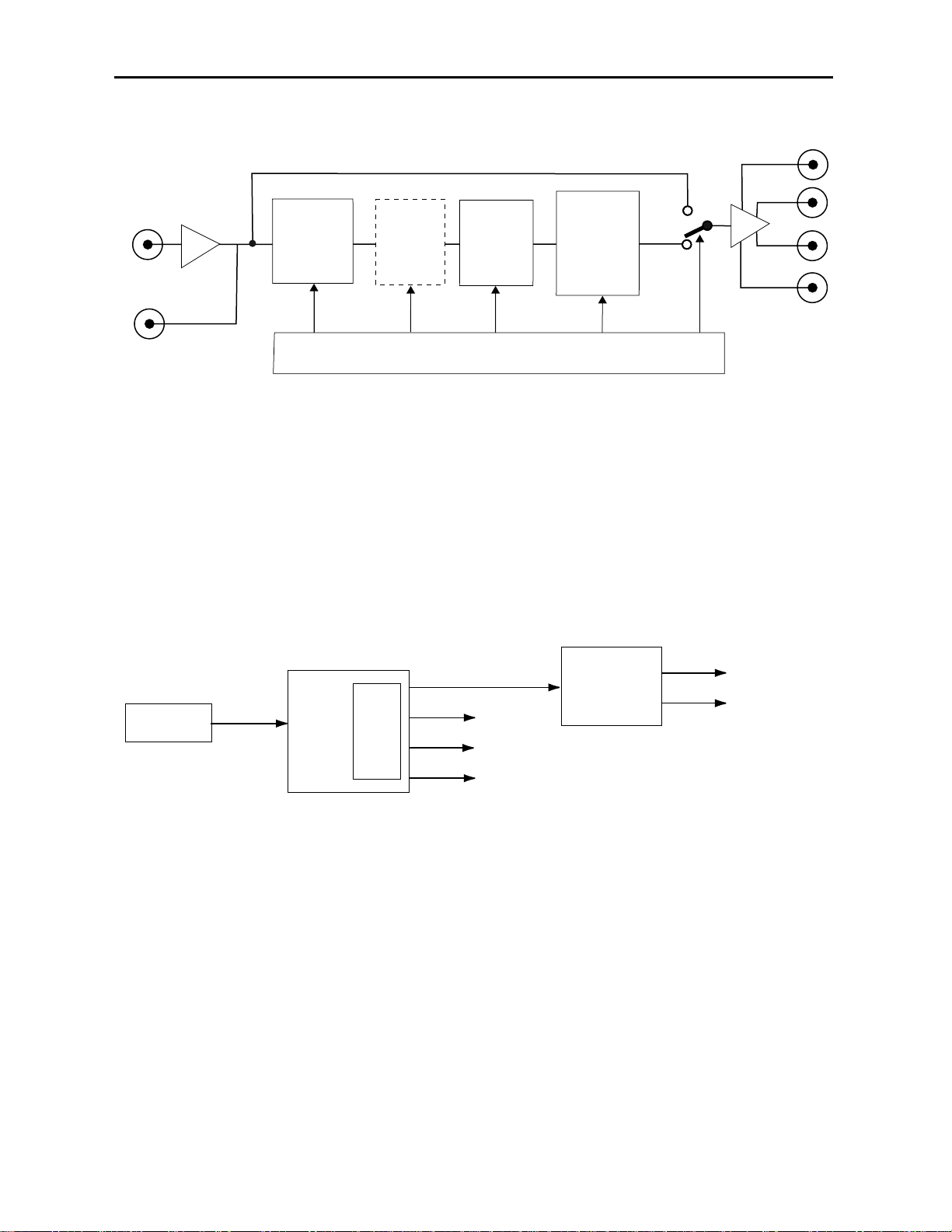
As illustrated in the block diagram on the next page, the serial input signal enters the
module and passes through receiver and serial decoder circuitry where the input stream is
deserialized and EDH information is monitored. The serial output of the receiver is routed
to the reclocked Loop Out BNC on the rear of the module. It is also directed by the user to
either the processing circuitry for adjusting gains, pedestal, black levels and hue or,
through the bypass path to the serial outputs if no processing is desired.
When the optional 5475 DNR (Digital Noise Reduction) submodule is installed, the processing continues through dynamic noise reduction and filtering circuitry based on
controls set by the user.
The next processing stage is composed of detail enhancing filters which allow recovery of
information lost due to poor frequency response in upstream systems. Controls are
provided for setting luminance and chrominance sharpness values.
The final digital processing stage is the Legalizer and clip circuitry. Clip adjustments for
black/white and chroma high/low levels are provided in the menus. Certain values represented in serial digital component may be illegal in the NTSC or PAL domains. The 5470’s
Predictive Composite Clipper mode looks for and alters those values that would be illegal
in analog composite, ensuring the output can be used for transmission.
The output stage of the module inserts and updates EDH before the signal is distributed
to the four Serial Output BNCs on the rear of the frame.
Embedded audio and ancillary data can be passed or stripped as directed by the user. If
the video processing path has any delay, the embedded audio is delayed accordingly.
Five memory registers are provided on the module for storing module setups. Different
setups can be created and stored for particular applications if needed or factory default
setting can be recalled at any time.
The on-board CPU can monitor and report module ID information (slot location, software
version and board revision), and power status to the optional frame System Control
module. This information can be accessed by the user or set to register an alarm if desired
using the remote control options available.
Model 5470 Digital Proc Amp and Model 5475 DNR
5470/5475-2
Page 3
Model 5470 Digital Proc Amp and Model 5475 DNR
APPLICATIONS
As shown in the example below, a typical use for the 5470 module would be for conditioning a potentially noisy 601 signal source, such as a satellite feed. After removing errors
and legalizing the signal it can then be distributed to analog and digital sources within
legal limits for all types of applications.
INSTALLATION
Plug the 5470 module into any one of the slots in the 1 RU or 3 RU frame and install the
plastic overlay provided onto the corresponding group of rear BNC connectors associated
with the module location. Note that the plastic overlay has an optional adhesive backing
for securing it to the frame. Use of the adhesive backing is only necessary if you would
like the location to be permanent and is not recommended if you need to change module
locations. This module may be hot-swapped (inserted or removed) without powering down
or disturbing performance of the other modules in the system.
5470/5475-3
5475/5470 Digital Processing Amplifier and Legalizer Block Diagram
5470/5475 Digital Processing Amplifier and Legalizer Application
Bypass Path
Serial
Outputs
Serial
Input
Loopback
Output
Gains
Pedestal
Black Bal
Hue
5475
DNR
Option
Detail
Enhance
Control System
Legalizer,
Black/White
Chroma,
Predictive
Composite
Clip
5200 DAC
Analog
Destinations
Satellite
601
5470
Digital Proc Amp
5475
DNR
Processed
601
Digital
Destinations
Page 4
Model 5470 Digital Proc Amp and Model 5475 DNR
5470/5475-4
5475 SUBMODULE
Install the 5475 DNR submodule in the connector closest to the rear of the module labeled
J6). The submodule is keyed for proper insertion. Match the connector on the submodule
to the connectors on the top of the 5470 circuit board. Be sure to check pin alignment
before seating the submodule.
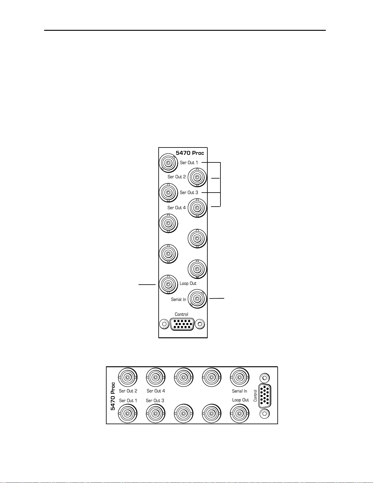
CABLING
Refer to the 3 RU and 1 RU backplane diagrams of the module below for cabling instructions. Note that unless stated otherwise, the 1 RU cabling explanations are identical to
those given in the 3 RU diagram.
Connect the processed signals
from Ser Out 1 – 4 BNCs to
601 destinations.
Connect the serial 601 input
signal to the Serial In BNC.
1 RU Backplane
Use the Loop Out BNC to
loop the reclocked serial input
signal to other destinations.
3 RU Backplane
Page 5

MODULE CONFIGURATION AND CONTROL
The configuration parameters for each Avenue module must be selected after installation.
This can be done remotely using one of the Avenue remote control options or locally using
the module front panel controls. Each module has a REMOTE/LOCAL switch on the
front edge of the circuit board which must first be set to the desired control mode.
The configuration parameter choices for the module will differ between Remote and
Local modes. In Remote mode, the choices are made through software and allow more
selections. The 5470/5475 Parameter Table on the following pages summarizes and
compares the various configuration parameters that can be set remotely or locally and the
default/factory settings.
If you are not using a remote control option, the module parameters must be configured
from the front panel switches. Parameters that have no front panel control will be set to a
default value. The Local switches are illustrated in the Front Panel Controls and
Indicators section following the 5470/5475 Parameter Table.
Avenue module parameters can be configured and controlled remotely from one or both of
the remote control options, the Avenue Touch Screen or the Avenue PC Application. Once
the module parameters have been set remotely, the information is stored on the module
CPU. This allows the module be moved to a different cell in the frame at your discretion
without losing the stored information. Remote configuration will override whatever the
switch settings are on the front edge of the module.
For setting the parameters remotely using the Avenue PC option, refer to the Avenue PC
Remote Configuration section of this document.
For setting the parameters remotely using the Avenue Touch Screen option, refer to the
Avenue Touch Screen Remote Configuration section of this data pack following
Avenue PC.
Model 5470 Digital Proc Amp and Model 5475 DNR
5470/5475-5
Page 6
Model 5470 Digital Proc Amp and Model 5475 DNR
5470/5475-6
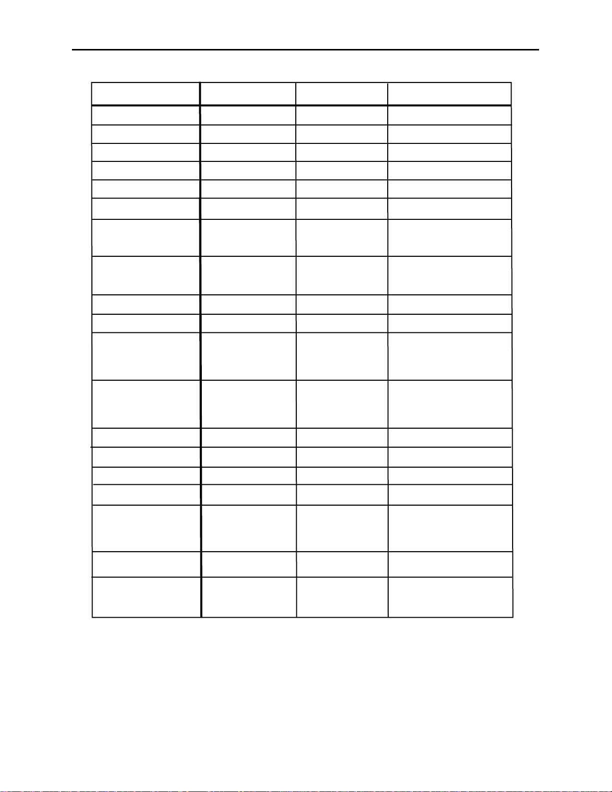
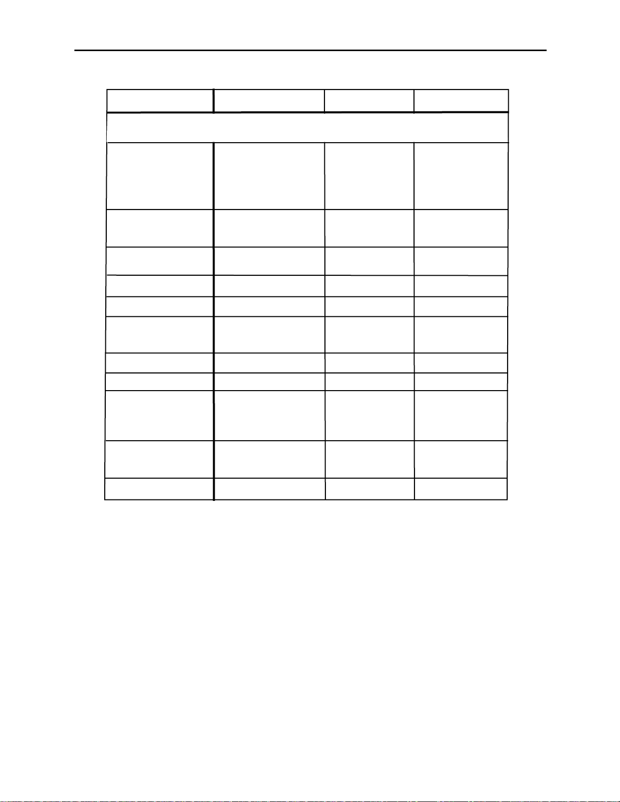
5470/5475 Parameter Table
CONTROL
Gain
Chroma
Pedestal
Hue
Black Clip
White Clip
Legalizer
Chr Clip Mode
Chr Lo Clip
Chr Hi Clip
Lum Sharp
LOCAL DEFAULT/FACTORY
N/A
N/A
N/A
N/A
N/A
N/A
Switch 1: Legal
Off
N/A
N/A
N/A
Switch 2: On
Off
REMOTE
0—150%
0—150%
+/- 30 IRE
+/- 180 degrees
— 8 to + 6.2 IRE
95 to 110 IRE
Off
Legal
Custom
Off
Chroma
Cpst
— 40 to +7.5 IRE
100 to 140 IRE
Off
1/4
1/2
Max
100%
100%
0
0
— 8 IRE
110 IRE
Off
Off
— 40 IRE
140 IRE
Max
Chr Sharp
Cb Offset
Cr Offset
Cb Gain
Cr Gain
Output Bypass
Blanking Mode
V Bit Pos
Switch 2: On
Off
N/A
N/A
N/A
N/A
Switch 7: Nor
Split
N/A
N/A
Off
1/4
1/2
Max
+/- 300
+/- 300
+/- 20
+/- 20
Normal
Bypass
Split
Split DNR
Narrow
Wide
Line 10
Line 20
Line 23
Max
0
0
0
0
Normal
Wide
Line 20
Page 7
Model 5470 Digital Proc Amp and Model 5475 DNR
5470/5475 Parameter Table (Continued)
5470/5475-7
CONTROL REMOTE LOCAL DEFAULT/FACTORY
When the 5475 DNR option is installed and enabled, the following
parameters in the local controls and DNR menu will be active:
Mode
Bypass
Luma
Luma NR Factor
Luma Threshold
Chroma
Chroma NR Factor
Chroma Threshold
Lum Bandwidth
(Hor Bwidth)
Switch 3: On
Off
N/A
N/A
N/A
N/A
N/A
N/A
N/A
Switch 4: On
Off
Automatic Lo
Automatic Hi
Adaptive
Adapt/Impulse1
Adapt/Impulse2
Non Adaptive
Normal
Bypass
Show Noise
On
Off
0 — 20 dB
0 — 250 IRE
On
Off
Luma Tie
0 — 20 dB
0 — 250 IRE
Normal
3/4 Band
1/2 Band
1/4 Band
Adaptive
Normal
On
6 dB
25 IRE
On
6 dB
25 IRE
Normal
Chr Bandwidth
Y/C Delay
N/A
N/A
Normal
3/4 Band
1/2 Band
+/-148 ns
Normal
0 ns
Page 8
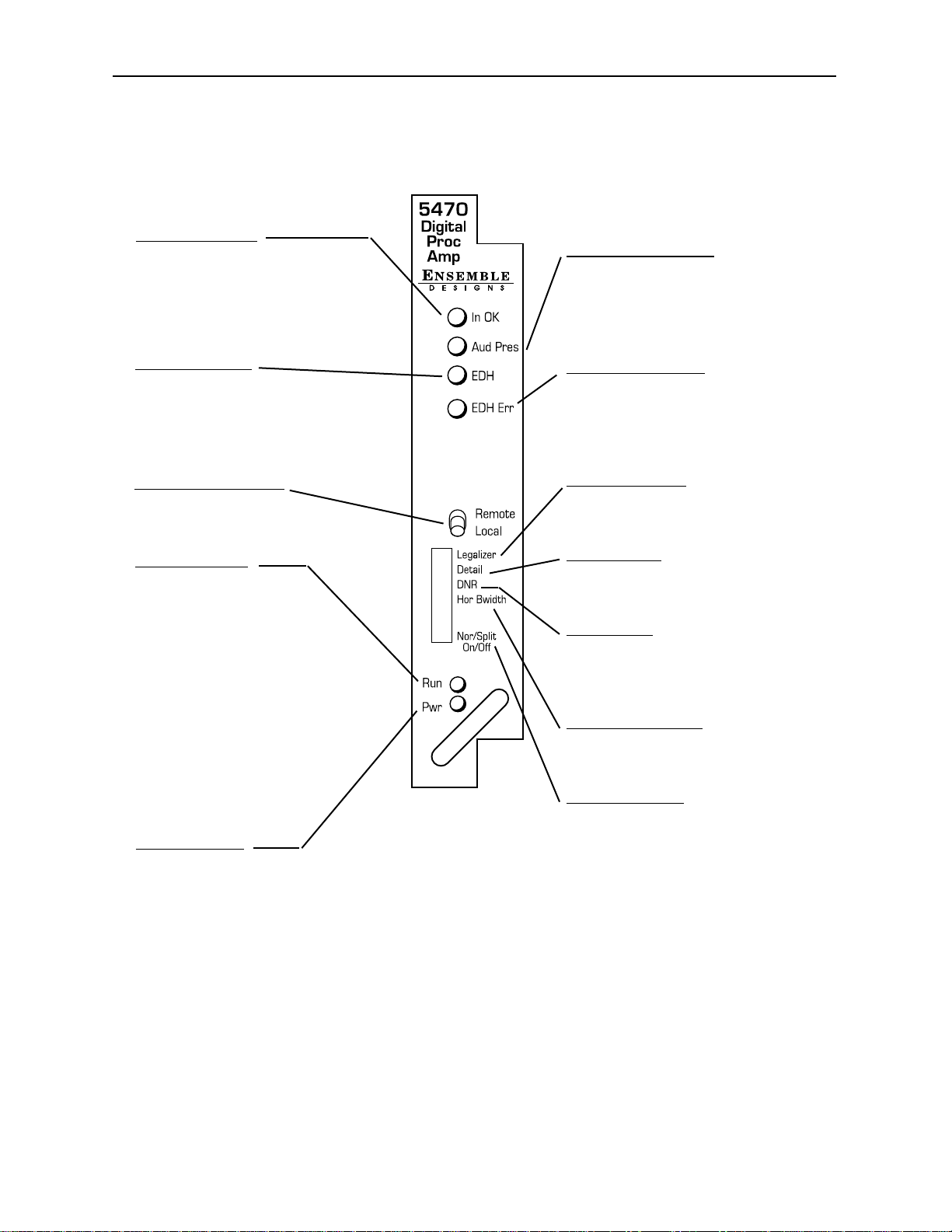
Front Panel Controls and Indicators
Each front edge indicator and switch setting is shown in the diagram below:
5470/5475-8
Remote/Local switch:
Set to the mode you
will be using.
Pwr green LED:
Indicates the presence (ON) or
absence (OFF) of power (+5V).
Run green LED:
OFF:
A power fault or halted CPU
ON:
A halted CPU
FAST BLINK:
CPU Run error
SLOW BLINK:
System OK. (If SPI control is
active from the main frame
System Control Module, all
Run indicators will be synchronized.).
In OK green LED:
On when the serial input has been
successfully equalized and the
serial receiver has locked to it
OFF when serial input has not
been equalized and is not locked.
Model 5470 Digital Proc Amp and Model 5475 DNR
EDH green LED:
On when EDH ancillary data is
detected in serial input stream.
OFF when no EDH ancillary data is
detected in serial input stream.
Legalizer switch:
Select On (left) to enable module
processing or Off (right) for
bypassing all processing.
Detail
switch:
Select On (left) to enable Detail
Enhancer processing or Off (right)
for no Detail Enhancer processing.
DNR
switch:
Select On (left) to enable DNR noise
reduction processing or Off (right) to
bypass DNR processing. Active
when 5475 DNR option is installed.
Hor Bwidth
switch:
Set to Full (left) or Limited (right)
horizontal bandwidth. Active when
5475 DNR option is installed.
Nor/Split
switch:
Select Nor (left) for a normal screen
output or Split (right) for a split
screen comparison between the
original serial input and the
processed output signal.
Aud Pres green LED:
On when audio ancillary data is
detected in serial input stream.
OFF when no audio ancillary data
is detected in serial input stream.
EDH
Error red LED:
On when CRC errors are detected
in the serial input data stream.
OFF when no CRC errors are
detected in serial input stream.
Page 9
Avenue PC Remote Configuration
The Avenue PC remote control status menus for this module are illustrated and explained
below. Refer to the 5470/5475 Parameter Table for a summary of available parameters
that can be set remotely through the menus illustrated. For more information on using
Avenue PC, refer to the Avenue PC Control Application Software data pack that came with
the option.
5470/5475 Avenue PC Menus
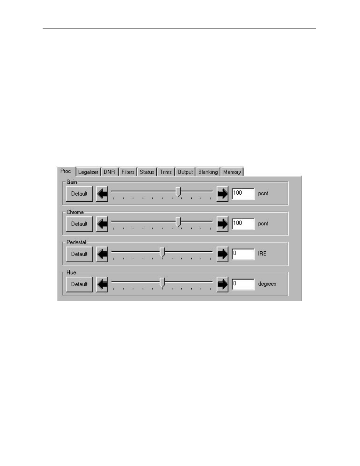
The Proc menu sets the following digital signal processing parameters for the signal:
• Gain – adjusts the percent of overall gain (luminance and chrominance).
• Chroma Gain – adjusts the percent of chroma amplitude.
• Pedestal – sets the pedestal (black) level ± 30 IRE.
• Hue – adjust the hue of the input signal ± 180 degrees.
5470/5475-9
Model 5470 Digital Proc Amp and Model 5475 DNR
Page 10
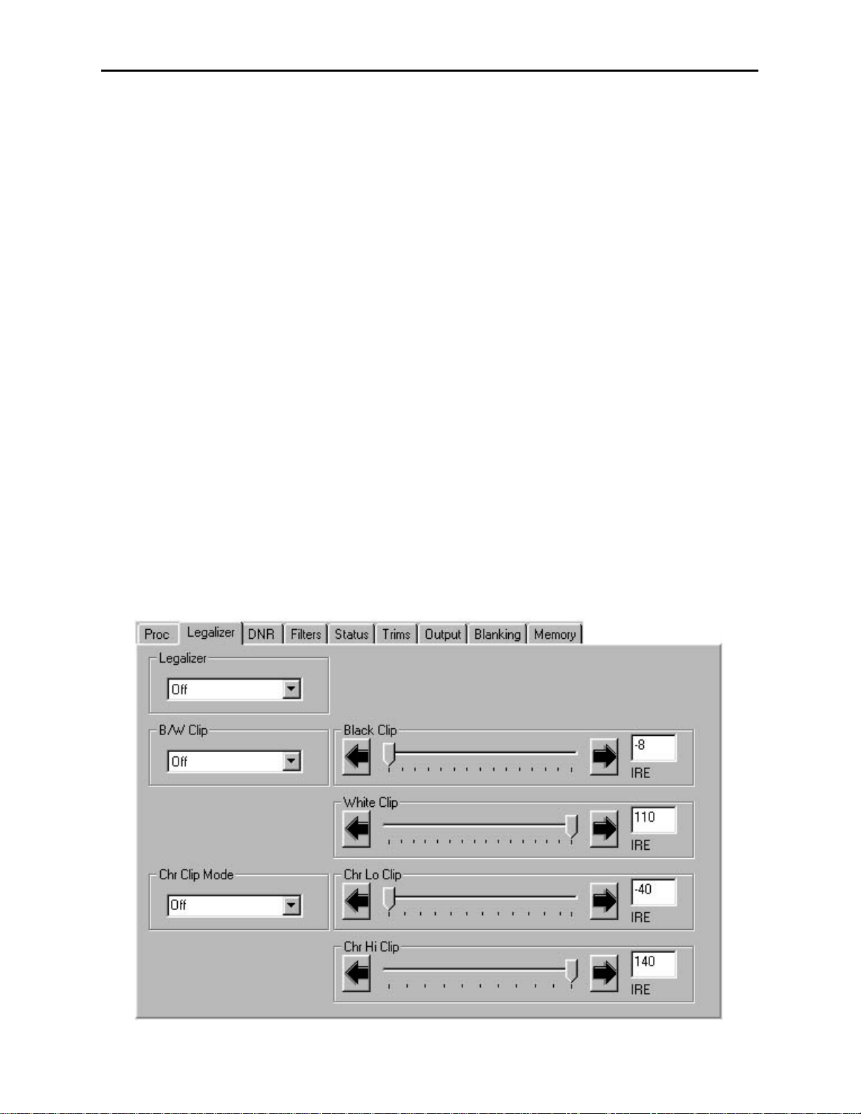
The Legalizer menu allows you to enable the Legalizer function to limit the input signal
black and white clip levels and the chroma clip levels with the following controls:
• Legalizer – set the legalizer function to one of the following:
Off – to disable it.
Legal – to apply the following factory preset parameters:
• B/W Clip is On.
• Black Clip is set to – 2.5 IRE.
• White Clip is set to + 105 IRE.
• Chr Clip Mode is Predictive Composite.
• Chr Lo Clip is set to – 20 IRE.
• Chr Hi Clip is set to + 120 IRE.
Custom to use the controls described below to set custom parameters.
• B/W Clip – select On to enable Black and White Clip functions or Off to
disable them.
• Black Clip – set the threshold for the black clip level to between – 8 and +
6.2 IRE (no content will be allowed below the level set).
• White Clip – sets the threshold for the white clip level to between 95 and
110 IRE (no content will be allowed above the level set).
• Chr Clip Mode – select Off for no chroma clip functions. Select Chroma to
use the Chr Lo Clip and Chr Hi Clip controls to clip the chroma content
(irrespective of the luminance). Select Cpst to enable the Predictive
Composite Clipper. This mode allows you to ensure that when the signal is
encoded to PAL or NTSC the minimum and maximum chroma excursions do
not exceed preset levels. Because in composite video, the chroma rides on
the luminance, this clip mode is based on chroma and luminance values.
Model 5470 Digital Proc Amp and Model 5475 DNR
5470/5475-10
Page 11

Model 5470 Digital Proc Amp and Model 5475 DNR
• Chr Lo Clip – set the low chroma clip level to between – 40 and 0 IRE
(– 20 typical).
• Chr Hi Clip – set the high chroma clip level to between 100 and 140 IRE
(+ 120 typical).
The DNR menu is active when the 5475 DNR (Digital Noise Reduction) submodule option
is installed on the 5470 module.
The 5475 submodule removes unwanted noise and artifacts. It is motion and scene
adaptive. Recursive Temporal Noise filtering includes Simple Recursive, Motion Adaptive
and Motion Adaptive with impulse filter. Controls are provided for maximum signal to
noise improvement and for noise threshold. These can be set manually or run in
automatic mode.
Motion Adaptive Recursive Noise filtering works on a pixel by pixel basis, comparing the
current frame to frames that have already been filtered. If the change detected is small, it
is considered noise, if detected as large, it is considered motion or scene change. The
detection process uses an LMMSE (Linear Minimum Mean Square Error) filtering
algorithm to evaluate the presence of motion. Combining this algorithm with recursive
temporal filters preserves fine detail while reducing noise in the presence of motion,
including rapidly moving objects and scene changes. Motion trails are minimized while
avoiding hard motion failures that some adaptive noise filters can exhibit.
User controls for the Motion Adaptive Recursive filter include a Noise Threshold, based on
how much noise is present in the incoming signal, and Maximum Signal to Noise improvement, based on how much noise removal is desired. The threshold setting can be
automatic or user adjustable.
When set to Automatic, the noise level of the input signal is measured and the threshold
is set accordingly. This simplifies the setup of the noise reducer and makes it responsive
to varying input signal to noise levels. The need for operator intervention is minimized to
accommodate feeds of differing quality. Two types of automatic noise reduction are offered,
Automatic Lo or Automatic Hi.
When the combined Motion Adaptive Recursive and Impulse Noise filter is selected,
temporal impulse noise filter removes high level, narrow noise impulses—without
reducing fine stationary detail.
The output mode of the DNR can be set with the selections under the Bypass pulldown.
This selection is used in conjunction with the module bypass setting in the Output menu.
The Show Noise output mode displays which areas of the picture are being affected by the
noise reducer. Noise is represented by white or black, while unaffected areas are represented in gray. This handy mode makes it easy to set optimum adjustments for the
material being processed. The Split Screen mode lets you compare the processed output to
the original signal.
In addition to the 5475 motion adaptive temporal filters, horizontal bandwidth filtering
and luma-chroma delay filters are provided in the Filters menu. The luma delay path can
be adjusted relative to the chroma path delay (Y/C Delay function in the Trims menu) in
approximately 2 ns subpixel steps, providing the ability to correct luma-chroma delay
errors in serial digital signals.
5470/5475-11
Page 12

The DNR menu shown below sets the following parameters:
• Mode – set the mode of noise reduction based on the type of noise and the amount
of motion in the signal. Set the Mode to one of the following:
Automatic Lo – this setting is completely automatic and requires no user
adjustments. The adjustments for Noise Reduction (NR) and Threshold
change depending on the source material. Luma and Chroma filters and
Chroma/Luma tie are on. This mode uses the Impulse 1 filter. This setting
removes a moderate amount of noise and shows little motion artifacts. It is
most useful for signals that vary a great deal and require less operator
intervention.
Automatic Hi – this setting is also completely automatic and requires no
user adjustments. The adjustments for enhanced for noise reduction (NR)
and Threshold. Luma and Chroma filters and Chroma/Luma tie are on. This
mode uses the Impulse 2 filter (also temporal). All noise is removed in this
mode and chances are higher for motion artifacts to appear.
Adaptive – this mode requires manual settings of all parameters. With
this mode, fine detail is preserved and motion is removed. Best used for
signals with less motion and results viewed with the Show Noise function
and a waveform monitor.
Adaptive/Impulse 1 – this mode is similar to the Adaptive mode above but
adds an Impulse 1 filter control. This allows removal of impulse noise —
large, narrow amplitude noise with a very high bandwidth (narrow). This
filter requires detail to be very fine before it will be removed. It is best for
removing fine sparkles in the video. Some fine moving details, such as rain,
can soften and blur with this filter enabled and so is not recommended for
this type of scene.
Adaptive/Impulse 2 – this mode is similar to the Adaptive/Impulse 1 mode
above but adds an Impulse 2 filter control. This allows removal of a wider
bandwidth of impulse noise. As a result, scenes with bigger detail will be
affected. This is also an effective filter for removing sparkles but blurring
and softening of detail will be more obvious than the Impulse 1 filter.
Non Adaptive – this filter is the most effective for still pictures. Noise
reduction can be set to the highest level with the luma and chroma NR and
threshold controls to produce the best results. Not recommended for pictures
with any motion.
Model 5470 Digital Proc Amp and Model 5475 DNR
5470/5475-12
Page 13

• Luma – the luma channel can be adjusted independently of the chroma channel for
noise reduction and motion threshold while in any of the Motion Adaptive
Recursive modes. These controls are best set using a waveform monitor and setting
the Show Noise function in the Bypass menu below.
• Chroma – the noise reduction and threshold of the chroma channel can be
adjusted independently of the luma channel with these controls. A Luma Tie
setting is provided that controls the chroma filter based on the motion estimation
on the luma channel. Not only is noise more effectively reduced when this control is
active, but it can also reduce the appearance of cross-color artifacts from poor
upstream decoding of composite signals.
• Bypass – set the DNR output mode in conjunction with the Output menu Bypass
function with this control. You may use this control to view the desired DNR output
for comparing noise reduction or detail enhancement. Refer to the Output menu
for details on setting this mode.
The Filters menu shown below allows setting the luminance and chroma sharpness and
horizontal bandwidth (with DNR option) with the following detail enhancing controls:
• Lum Sharp – set to Off to bypass detail enhancing filters. Set to Off , 1/4, 1/2, or
Max to set the sharpness of the luminance portion of the signal.
• Chr Sharp – set to Off to bypass detail enhancing filters. Set to Off, 1/2, 1/4, or
Max to set the sharpness of the chrominance portion of the signal.
• Lum Bandwidth – used only when the 5475 DNR (Digital Noise Reduction)
option is installed. Set to Normal to allow full bandwidth (no effect), or 3/4 Band,
1/2 Band, or 1/4 Band.
• Chr Bandwidth – used only when the 5475 DNR (Digital Noise Reduction) option
is installed. Set to Normal to allow full bandwidth (no effect), or 3/4 Band,
or 1/2 Band..
These bandwidth functions utilize filtering applying a sharp cutoff low-pass filter
to effectively remove high frequency and impulse noise. This is especially useful in
applications such as an MPEG pre-processor to reduce bandwidth required to
transmit an MPEG-encoded signal. The result can be a cost effective method of
delivering video via satellite link.
5470/5475-13
Model 5470 Digital Proc Amp and Model 5475 DNR
Page 14

The Status menu shown below gives the read-only status of the following:
• Input – indicates if the serial input signal is being equalized and the serial
receiver is locking to it.
• Audio – indicates if embedded audio is detected in the input data stream.
• Option – indicates whether the 5475 DNR submodule option is installed.
• EDH Error – indicates No Error if proper EDH is present, No EDH if EDH is
not present, and No Input if there is no serial input present. When an EDH error
is detected, it will be indicted by a specific EDH error code.
• Error Seconds – displays the number of seconds that a detected EDH error has
been present in the serial data stream.
Model 5470 Digital Proc Amp and Model 5475 DNR
5470/5475-14
Page 15

The Trims menu allows you to correct subtle issues in the individual color difference
channels with offset and gain controls. The offset controls adjust the DC offsets above or
below the nominal points. This can be used to correct black balance errors. The gain
controls adjust the amplitude of each channel. It is helpful to set the output of the module
to Split Screen (in the Output menu) to allow viewing a comparison of the processed
signal to the input while adjusting the controls below.
Use the controls described below to make the offset and gain corrections:
• Cb Offset – adjust the DC offset of the Cb channel to between ± 300.
• Cr Offset – adjust the DC offset of the Cr channel to between ± 300.
• Cb Gain – adjust the amplitude of the Cb channel to between ± 20.
• Cr Offset – adjust the amplitude of the Cr channel to between ± 20.
• Y/C Delay – used only when the 5475 DNR (Digital Noise Reduction) option is
installed. Adjust the amount of luminance to chrominance delay to between
± 148 ns.
Model 5470 Digital Proc Amp and Model 5475 DNR
5470/5475-15
Page 16

The Output menu allows you to set the state of the output with the following:
• Bypass – set to Normal for no split screen, Bypass, to completely bypass any
digital processing, or Split or Split DNR to enable a split screen comparison
between the original input signal (left) and the processed output (right). Use this
control in conjunction with the Bypass control in the DNR menu as described in
the summary table below.
• Strip Audio – select the box to strip embedded audio from the output. Leave the
box unselected to pass embedded audio through to the output.
Model 5470 Digital Proc Amp and Model 5475 DNR
5470/5475-16
Output and DNR Menu Bypass Mode Table
Output Menu
Bypass Setting
Normal
Bypass
Split
Split DNR
DNR Menu
Bypass Setting
Normal
Bypass
Show Noise
Any Setting
Normal
Bypass
Show Noise
Normal
Bypass
Output Condition
All processing on.
All DNR processing is off.
DNR controls are grayed out.
DNR processing is on. Show noise
function is full screen with all DNR controls.
All processing is bypassed.
All controls grayed out.
Left side of screen unprocessed,
right side of screen processed with DNR.
All controls active for DNR.
Left side of screen unprocessed,
right side processed without DNR.
DNR controls grayed out.
Left side of screen unprocessed,
right side of screen processed with DNR.
All controls active.
Left side of screen processed without DNR,
right side of screen processed with DNR.
All controls active.
Left side of screen processed without DNR,
right side of screen processed without DNR,
All DNR controls grayed out.
Show Noise
Left side of screen processed without DNR,
right side processed with Show Noise,
All DNR controls active.
Page 17

The Blanking menu allows you to select the blanking mode desired for the output with
the following:
• Mode – set the blanking mode to either Wide (content in the vertical interval is
blanked) or Narrow (content of the vertical interval is passed).
• V Bit Pos – in 525 mode only. Set the position of the vertical bit in the 601 output
to Line 10, Line 20 or Line 23.
The Memory menu allows you to save overall module setups into up to five memory
registers as follows:
• Select Save, then one of the five memory registers Reg 1 – 5. The box will turn
green. The entire module setup is now saved in the selected register.
• To recall a register, select the register box. If there is information saved, the box
will turn green. The saved setup will now be loaded to the module. Up to five
different module setups can be saved and recalled using the individual registers.
Model 5470 Digital Proc Amp and Model 5475 DNR
5470/5475-17
Page 18

Avenue Touch Screen Remote Configuration
The Avenue Touch Screen remote control status menus for this module are illustrated and
explained below. Refer to the 5470 Parameter Table for a summary of available parameters that can be set remotely through the menus illustrated. For more information on
using the Avenue Touch Screen, refer to the Avenue System Overview.
5470 Avenue Touch Screen Menus
The Proc menu sets the following digital signal processing parameters for the signal:
• Gain – adjusts the percent of overall gain (luminance and chrominance).
• Chroma Gain – adjusts the percent of chroma amplitude.
• Pedestal – sets the pedestal (black) level ± 30 IRE.
• Hue – adjust the hue of the input signal ± 180 degrees.
5470/5475-18
Model 5470 Digital Proc Amp and Model 5475 DNR
Page 19

Model 5470 Digital Proc Amp and Model 5475 DNR
The Legalizer menu allows you to enable the Legalizer function to limit the input signal
black and white clip levels and the chroma clip levels with the following controls:
• Legalizer – set the legalizer function to one of the following:
Off – to disable it.
Legal – to apply the following factory preset parameters:
• B/W Clip is On.
• Black Clip is set to – 2.5 IRE.
• White Clip is set to + 105 IRE.
• Chr Clip Mode is Predictive Composite.
• Chr Lo Clip is set to – 20 IRE.
• Chr Hi Clip is set to + 120 IRE.
Custom to use the controls described below to set custom parameters.
• B/W Clip – select On to enable Black and White Clip functions or Off to
disable them.
• Black Clip – set the threshold for the black clip level to between – 8 and +
6.2 IRE (no content will be allowed below the level set).
• White Clip – sets the threshold for the white clip level to between 95 and
110 IRE (no content will be allowed above the level set).
• Chr Clip Mode – select Off for no chroma clip functions. Select Chroma to
use the Chr Lo Clip and Chr Hi Clip controls to clip the chroma content
(irrespective of the luminance). Select Cpst to enable the Predictive
Composite Clipper. This mode allows you to ensure that when the signal is
encoded to PAL or NTSC the minimum and maximum chroma excursions do
not exceed preset levels. Because in composite video, the chroma rides on
the luminance, this clip mode is based on chroma and luminance values.
• Chr Lo Clip – set the low chroma clip level to between – 40 and 0 IRE
(– 20 typical).
• Chr Hi Clip – set the high chroma clip level to between 100 and + 140 IRE
(+ 120 typical).
5470/5475-19
Page 20

The DNR menu is active when the 5475 DNR (Digital Noise Reduction) submodule option
is installed on the 5470 module.
The 5475 submodule removes unwanted noise and artifacts. It is motion and scene
adaptive. Recursive Temporal Noise filtering includes Simple Recursive, Motion Adaptive
and Motion Adaptive with impulse filter. Controls are provided for maximum signal to
noise improvement and for noise threshold. These can be set manually or run in
automatic mode.
Motion Adaptive Recursive Noise filtering works on a pixel by pixel basis, comparing the
current frame to frames that have already been filtered. If the change detected is small, it
is considered noise, if detected as large, it is considered motion or scene change. The
detection process uses an LMMSE (Linear Minimum Mean Square Error) filtering
algorithm to evaluate the presence of motion. Combining this algorithm with recursive
temporal filters preserves fine detail while reducing noise in the presence of motion,
including rapidly moving objects and scene changes. Motion trails are minimized while
avoiding hard motion failures that some adaptive noise filters can exhibit.
User controls for the Motion Adaptive Recursive filter include a Noise Threshold, based on
how much noise is present in the incoming signal, and Maximum Signal to Noise improvement, based on how much noise removal is desired. The threshold setting can be
automatic or user adjustable.
When set to Automatic, the noise level of the input signal is measured and the threshold
is set accordingly. This simplifies the setup of the noise reducer and makes it responsive
to varying input signal to noise levels. The need for operator intervention is minimized to
accommodate feeds of differing quality. Two types of automatic noise reduction are offered,
Automatic Lo or Automatic Hi.
When the combined Motion Adaptive Recursive and Impulse Noise filter is selected,
temporal impulse noise filter removes high level, narrow noise impulses—without
reducing fine stationary detail.
The output mode of the DNR can be set with the selections under the Bypass pulldown.
This selection is used in conjunction with the setting in the Output menu. The Show
Noise output mode displays what areas of the picture are being affected by the noise
reducer. Noise is represented by white or black, while unaffected areas are represented in
gray. This handy mode makes it easy to set optimum adjustments for the material being
processed. The Split Screen mode lets you compare the processed output to the original
signal.
In addition to the 5475 motion adaptive temporal filters, horizontal bandwidth filtering
and luma-chroma delay filters are provided in the Filters menu. The luma delay path can
be adjusted relative to the chroma path delay (Y/C Delay function in the Trims menu) in
approximately 2 ns subpixel steps, providing the ability to correct luma-chroma delay
errors in serial digital signals.
Model 5470 Digital Proc Amp and Model 5475 DNR
5470/5475-20
Page 21

The DNR menu shown below sets the following parameters:
• Mode – set the mode of noise reduction based on the type of noise and the amount
of motion in the signal. Set the Mode to one of the following:
Automatic Lo – this setting is completely automatic and requires no user
adjustments. The adjustments for Noise Reduction (NR) and Threshold
change depending on the source material. Luma and Chroma filters and
Chroma/Luma tie are on. This mode uses the Impulse 1 filter. This setting
removes a moderate amount of noise and shows little motion artifacts. It is
most useful for signals that vary a great deal and require less operator
intervention.
Automatic Hi – this setting is also completely automatic and requires no
user adjustments. The adjustments for enhanced for noise reduction (NR)
and Threshold. Luma and Chroma filters and Chroma/Luma tie are on.
This mode uses the Impulse 2 filter (also temporal). All noise is removed in
this mode and chances are higher for motion artifacts to appear.
Adaptive – this mode requires manual settings of all parameters. With
this mode, fine detail is preserved and motion is removed. Best used for
signals with less motion and results viewed with the Show Noise function
and a waveform monitor.
Adaptive/Impulse 1 – this mode is similar to the Adaptive mode above but
adds an Impulse 1 filter control. This allows removal of impulse noise —
large, narrow amplitude noise with a very high bandwidth (narrow). This
filter requires detail to be very fine before it will be removed. It is best for
removing fine sparkles in the video. Some fine moving details, such as rain,
can soften and blur with this filter enabled and so is not recommended for
this type of scene.
Adaptive/Impulse 2 – this mode is similar to the Adaptive/Impulse 1 mode
above but adds an Impulse 2 filter control. This allows removal of a wider
bandwidth of impulse noise. As a result, scenes with bigger detail will be
affected. This is also an effective filter for removing sparkles but blurring
and softening of detail will be more obvious than the Impulse 1 filter.
Model 5470 Digital Proc Amp and Model 5475 DNR
5470/5475-21
Page 22

Non Adaptive – this filter is the most effective for still pictures. Noise
reduction can be set to the highest level with the luma and chroma NR and
threshold controls to produce the best results. Not recommended for pictures
with any motion.
• Luma – the luma channel can be adjusted independently of the chroma channel for
noise reduction and motion threshold while in any of the Motion Adaptive
Recursive modes. These controls are best set using a waveform monitor and setting
the Show Noise function in the Bypass menu below.
• Chroma – the noise reduction and threshold of the chroma channel can be
adjusted independently of the luma channel with these controls. A Luma Tie
setting is provided that controls the chroma filter based on the motion estimation
on the luma channel. Not only is noise more effectively reduced when this control is
active, but it can also reduce the appearance of cross-color artifacts from poor
upstream decoding of composite signals.
• Bypass – set the DNR output mode with this control. You may use this control to
split the screen for comparing noise reduction or detail enhancement. Refer to the
Output menu for more details on setting this mode.
Model 5470 Digital Proc Amp and Model 5475 DNR
5470/5475-22
Page 23

The Filters menu shown below allows setting the luminance and chroma sharpness and
horizontal bandwidth (with DNR option) with the following detail enhancing controls:
• Lum Sharp – set to Off to bypass detail enhancing filters. Set to Off , 1/4, 1/2, or
Max to set the sharpness of the luminance portion of the signal.
• Chr Sharp – set to Off to bypass detail enhancing filters. Set to Off, 1/2, 1/4, or
Max to set the sharpness of the chrominance portion of the signal.
• Lum Bandwidth – used only when the 5475 DNR (Digital Noise Reduction)
option is installed. Set to Normal to allow full bandwidth (no effect), or 3/4 Band,
1/2 Band, or 1/4 Band.
• Chr Bandwidth – used only when the 5475 DNR (Digital Noise Reduction) option
is installed. Set to Normal to allow full bandwidth (no effect), or 3/4 Band,
or 1/2 Band..
These bandwidth functions utilize filtering applying a sharp cutoff low-pass filter
to effectively remove high frequency and impulse noise. This is especially useful in
applications such as an MPEG pre-processor to reduce bandwidth required to
transmit an MPEG-encoded signal. The result can be a cost effective method of
delivering video via satellite link.
Model 5470 Digital Proc Amp and Model 5475 DNR
5470/5475-23
Page 24

The Status menu shown below gives the read-only status of the following:
• Input – indicates if the serial input signal is being equalized and the serial
receiver is locking to it.
• Audio – indicates if embedded audio is detected in the input data stream.
• Option – indicates whether the 5475 DNR submodule option is installed.
• EDH Error – indicates No Error if proper EDH is present, No EDH if EDH is
not present, and No Input if there is no serial input present. When an EDH error
is detected, it will be indicted by a specific EDH error code.
• Error Seconds – displays the number of seconds that a detected EDH error has
been present in the serial data stream.
Model 5470 Digital Proc Amp and Model 5475 DNR
5470/5475-24
Page 25

Model 5470 Digital Proc Amp and Model 5475 DNR
The Trims menu allows you to correct subtle issues in the individual color difference
channels with offset and gain controls. The offset controls adjust the DC offsets above or
below the nominal points. This can be used to correct black balance errors. The gain
controls adjust the amplitude of each channel. It is helpful to set the output of the module
to Split Screen (in the Output menu) to allow viewing a comparison of the processed
signal to the input while adjusting the controls below.
Use the controls described below to make the offset and gain corrections:
• Cb Offset – adjust the DC offset of the Cb channel to between ± 300.
• Cr Offset – adjust the DC offset of the Cr channel to between ± 300.
• Cb Gain – adjust the amplitude of the Cb channel to between ± 20.
• Cr Offset – adjust the amplitude of the Cr channel to between ± 20.
• Y/C Delay – used only when the 5475 DNR (Digital Noise Reduction) option is
installed. Adjust the amount of luminance to chrominance delay to between
± 148 ns.
5470/5475-25
Page 26

The Output menu allows you to set the state of the output with the following:
• Bypass – set to Normal for no split screen, Bypass, to completely bypass any
digital processing, or Split or Split DNR to enable a split screen comparison
between the original input signal (left) and the processed output (right). Use this
control in conjunction with the Bypass control in the DNR menu as described in
the summary table on the next page.
• Strip Audio – select the box to strip embedded audio from the output. Leave the
box unselected to pass embedded audio through to the output.
Model 5470 Digital Proc Amp and Model 5475 DNR
5470/5475-26
Page 27

Model 5470 Digital Proc Amp and Model 5475 DNR
Output and DNR Menu Bypass Mode Table
5470/5475-27
Output Menu
Bypass Setting
Normal
Bypass
Split
Split DNR
DNR Menu
Bypass Setting
Normal
Bypass
Show Noise
Any Setting
Normal
Bypass
Show Noise
Normal
Bypass
Output Condition
All processing on.
All DNR processing is off.
DNR controls are grayed out.
DNR processing is on. Show noise
function is full screen with all DNR controls.
All processing is bypassed.
All controls grayed out.
Left side of screen unprocessed,
right side of screen processed with DNR.
All controls active for DNR.
Left side of screen unprocessed,
right side processed without DNR.
DNR controls grayed out.
Left side of screen unprocessed,
right side of screen processed with DNR.
All controls active.
Left side of screen processed without DNR,
right side of screen processed with DNR.
All controls active.
Left side of screen processed without DNR,
right side of screen processed without DNR,
All DNR controls grayed out.
Show Noise
Left side of screen processed without DNR,
right side processed with Show Noise,
All DNR controls active.
Page 28

Model 5470 Digital Proc Amp and Model 5475 DNR
The Blanking menu allows you to select the blanking mode desired for the output with
the following:
• Mode – set the blanking mode to either Wide (content in the vertical interval is
blanked) or Narrow (content of the vertical interval is passed).
• V Bit Pos – in 525 mode only. Set the position of the vertical bit in the 601 output
to Line 10, Line 20 or Line 23.
5470/5475-28
Page 29

Model 5470 Digital Proc Amp and Model 5475 DNR
The Memory menu allows you to save overall module setups into up to five memory
registers as follows:
• Select Save, then one of the five memory registers Reg 1 – 5. The entire module
setup is now saved in the selected register. The box will turn green indicating the
setting have been saved and that it is the last recalled (current) register.
• To recall a register, select the register box. If there is information saved, the box
will turn green. The saved setup will now be loaded to the module. Up to five
different module setups can be saved and recalled using the individual registers.
5470/5475-29
Page 30

TROUBLESHOOTING
As a troubleshooting aid, the input signal status and presence, power and CPU status can
be easily monitored from the front panel of this module using the front panel indicators.
Refer to the overall troubleshooting tips given below for the module:
Can’t control module:
• Check status of CPU Run green LED. Should be blinking slowly and in
unison with other modules if System module is present. If not, try removing
it and plugging it in again to be sure it is seated properly.
• System module may not be working properly if installed.
No signal out of module:
• Check status of In OK LED.
• Check EDH Err light is off.
• Check cabling to input of module.
You may also refer to the technical support section of the Ensemble Designs web site for
the latest information on your equipment at the URL below:
http://www
.ensembledesigns.com/support
SOFTWARE UPDATING
Software upgrades for each module can be downloaded remotely if the optional System
Control module is installed. These can be downloaded onto your PC and then Avenue PC
will distribute the update to the individual module. (Refer to the Avenue PC documentation for more information) Periodically updates will be posted on our web site. If you do
not have the required System Control Module and Avenue PC, modules can be sent back
to the factory for software upgrades.
5470/5475-30
Model 5470 Digital Proc Amp and Model 5475 DNR
Page 31

Model 5470 Digital Proc Amp and Model 5475 DNR
5470/5475-31
WARRANTYAND FACTORY SERVICE
Warranty
This module is covered by a five year limited warranty, as stated in the main Preface of
this manual. If you require service (under warranty or not), please contact Ensemble
Designs and ask for customer service before you return the unit. This will allow the
service technician to provide any other suggestions for identifying the problem and
recommend possible solutions.
Factory Service
If you return equipment for repair, please get a Return Material Authorization Number
(RMA) from the factory first.
Ship the product and a written description of the problem to:
Ensemble Designs, Inc.
Attention: Customer Service RMA #####
870 Gold Flat Rd.
Nevada City, CA. 95959 USA
(530) 478-1830
Fax: (530) 478-1832
service@endes.com
http://www.ensembledesigns.com
Be sure to put your RMA number on the outside of the box.
Page 32

SPECIFICATIONS
5470 Digital Proc Amp
Serial Input:
Number: One
Signal Type: Serial Digital (SMPTE 259M)
Impedance: 75 Ω
Return Loss: > 15 dB
Maximum Cable
Length 300 meters Belden 8281
Serial Output:
Number: Four
Signal Type: Serial Digital (SMPTE 259M)
Impedance: 75 Ω
Return Loss > 15 dB
Output DC None (AC coupled)
Delay < 8 µsec (1/8 line)
Serial Loop Thru Output:
Number: One, reclocked
Signal Type: Serial Digital (SMPTE 259M)
Impedance: 75 Ω
Return Loss > 15 dB
Output DC None (AC coupled)
Delay < 10 clocks
General Specifications:
Connectors: BNC
Power Consumption: < 7 Watts
Temperature Range: 0 to 40 degrees C ambient (all specs met)
Relative Humidity: 0 to 95% noncondensing
Altitude: 0 to 10,000 ft
Fusing: 1.5 Amp PTC resettable fuse
Due to ongoing product development, all specifications subject to change.
Model 5470 Digital Proc Amp and Model 5475 DNR
5470/5475-32
 Loading...