

Page 1
This data pack provides detailed installation, configuration and operation information for
the 5420 Digital Logo Inserter module as part of the Avenue Signal Integration
System.
The module information in this data pack is organized into the following sections:
• Module Overview
• Applications
• Installation
• Cabling
• Module Configuration and Control
°
Front Panel Controls and Indicators
°
Avenue PC Remote Control
°
Avenue Touch Screen Remote Control
• Troubleshooting
• Software Updating
• Warranty and Factory Service
• Specifications
5420-1
Model 5420
Digital Logo
Inserter
Data Pack
ENSEMBLE
DESIGNS
Revision 3.1 SW v2.0.0
Page 2

MODULE OVERVIEW
The 5420 Digital Logo Inserter module allows the keying (insertion) of a graphic image or
animation sequence over a serial digital program background. The keying operation is an
additive linear key with a density (transparency) control.
Three modes of operation are available: DSK, DSK Preview, or Fill/Key. In DSK mode, the
module keys the graphic over the serial digital background and outputs the entire signal
on the PGM output BNCs. In the DSK preview mode, selecting a new event causes an onair event to transition off. The new event is sent to the PVW output but not transitioned
on-air. Activating the Cut or Mix control puts the event on-air and also feeds it to the
PVW output. In Fill/Key mode, two serial digital outputs are provided so the module can
source a key and fill to a switcher’s DSK input if desired.
Graphic stills, logos and animation sequences can be authored in targa format with any
computer software desired. These stills, logos and animation sequences are collected and
named with a PC application called Avenue Logo that comes on a CD with the module.
They are then downloaded to non-volatile flash memory on the module using the application. Each image is stored in flash memory which can store up to 5 full frame images or
many smaller images, depending on their size. Total available storage is about 2 M pixels
or 8 MB. An average corner logo is approximately 100 x 100 pixels in size for a total area
of about 10,000 pixels, allowing the 5420 to store up to 200 average size logos. Each frame
in an animation sequences is considered one logo. Animation sequences can be up to 200
frames long (approximately 6.5 seconds in 525 mode).
Each logo can be defined by number, name, type and can be positioned horizontally and
vertically on an image by image basis using Avenue Logo or the Avenue remote control
system. In and out transition times can also be programmed for each image. A density
control allows changing the transparency of the key. These values are then stored for each
logo.
Images can be defined as events that can be cut or mixed on manually or triggered to
come on by GPI control from an external control device. Up to eight events can be defined
to correspond to the eight GPI inputs available on the Control connector on the rear of the
module. The 5815 Remote GPI panel can also be used to control the GPIs. GPI trigger 8
can be programmed to act as a regular GPI trigger or as a cut or mix control to transition
one of the other selected GPIs (1 – 7) as a cut or mix.
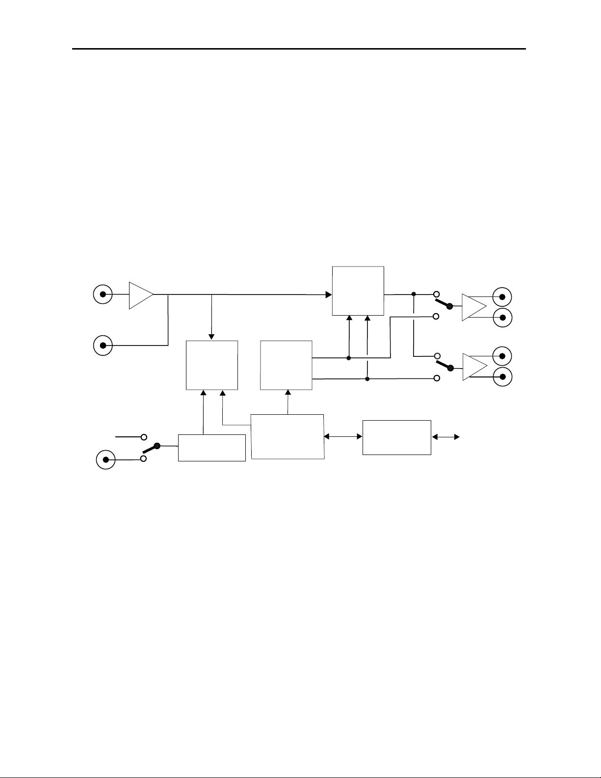
As shown in the 5420 functional block diagram on the following page, a serial digital background signal is fed to the module and enters a receiver/decoder circuit where it is
monitored for cable equalization and EDH processing. The reclocked background signal is
available from a loopback output BNC if needed. EDH status is reported for the input
signal.
The processed background signal then enters a linear keying circuit where the selected
key image cuts a hole in the background and the fill signal is added. When configured for
DSK mode, the background is added to the fill and a composited image of background with
key is available from the PGM output BNCs. Timing for the output signal is derived from
the serial input.
DSK w/Preview mode places the background and fill on the PVW output to be viewed
before being cut or mixed on-air as the next event.
Model 5420 Digital Logo Inserter
5420-2
Page 3
Model 5420 Digital Logo Inserter
When the module is configured for Fill/Key mode, black is added to the fill instead of the
background signal and the timing reference is selectable from the external video reference
BNC, the master frame reference or the serial input. The separate Fill and Key signals go
to their respective output BNCs for feeding a device such as a switcher. When an image is
selected as a key, it is directly transferred to the linear keying circuit.
The on-board CPU can monitor and report module ID information (slot location, software
version and board revision), and power status to the optional frame System Control
module. This information can be accessed by the user or set to register an alarm if desired
using the remote control options available.
Because the 5420 is an Avenue module, every function and parameter can be controlled
from an Avenue Touch Screen Control Panel, Avenue Express Panel, or the Avenue PC
Control Application. Memory registers can be used to save the complete configuration of
the module, making it easy to change instantly between different configurations.
5420-3
5420 Digital Logo Inserter Block Diagram
Bkgd
Input
Loop Back
Output
Timing
and
Memory
Control
Flash
Memory
Linear
Keyer
Fill
Key
Pgm/Fill
Pvw/Key
Master
Ref
Ext Ref
Sync Detector
Microprocessor
Avenue Control
System
Image T r ansfer
Page 4

APPLICATIONS
The 5420 module can be utilized in many ways to take advantage of its versatility. Some
keying tasks that can be performed by the 5420 include the following:
• Fixed or animated station and channel ID
• Copyright protection
• Emergency standby notification
• Gateway for downstream keys and masks from a graphic workstation
• Custom full-field test patterns/zone plates
The module can operate in DSK mode, DSK w/Preview, or Fill/Key mode. Examples of
common applications are given here.
DSK Mode
When the module is configured for DSK mode, a serial digital signal from a device such as
a Master Control switcher can be connected to the input and a graphic or logo from a PC
workstation can be inserted over the background to provide the final video as shown in
the example below. The PGM outputs can be fed to the transmitter and other destinations
and PVW outputs are available for monitoring.
Using the 5420 in DSK Mode
Model 5420 Digital Logo Inserter
5420-4
Master
Control
PGM Out
5420
PGM OUT
Bkgd In
Logo
PVW OUT
PC Workstation
Transmitter
PVW Monitor
Page 5

Model 5420 Digital Logo Inserter
5420-5
Fill/Key Mode
When the module is configured for Fill/Key mode, the background and key signal can be
used to supply separate Fill and Key signals to feed a Master Control switcher as an input
source, in a similar manner as a character generator. The 5420 can be genlocked to an
external reference to match the timing of the Master Control device as shown below.
Using the 5420 in Fill/Key Mode
Master
Control
Bkgd In
5420
Fill Out
Logo
PC Workstation
Key Out
PGM Out
Genlock
Source
Page 6

INSTALLATION
Plug the 5420 module into any one of the slots in the 1 RU or 3 RU frame and install the
plastic overlay provided onto the corresponding group of rear BNC connectors associated
with the module location. Note that the plastic overlay has an optional adhesive backing
for securing it to the frame. Use of the adhesive backing is only necessary if you would
like the location to be permanent and is not recommended if you need to change module
locations. This module may be hot-swapped (inserted or removed) without powering down
or disturbing performance of the other modules in the system.
CABLING
Refer to the 3 RU and 1 RU backplane diagrams of the module on the following page for
cabling instructions. Note that unless stated otherwise, the 1 RU cabling explanations are
identical to those given in the 3 RU diagram.
Control Devices
In addition to GPI access through the control system, the module provides eight GPI input
contact closures and control from a dedicated serial port both accessible through the
15-pin D Control connector on the corresponding rear slot of the frame.
Three types of devices can control the eight GPI inputs to the 5420 module; the Avenue
5815 GPI Control Panel, a customer-supplied GPI device and an external device (such as a
PC) using a Serial port connection. Connection of the 5815 GPI Control Panel and the GPI
device to the 5420 module and the cable pinouts for each application are given in the next
sections. Refer to Appendix A for the details for connecting an external device such as a
PC, including the serial protocol.
5420-6
Model 5420 Digital Logo Inserter
Page 7

5420-7
Model 5420 Digital Logo Inserter
3 RU Backplane
Connect the Background serial
signal to the Serial In BNC.
Connect an external genlock
reference signal to the Ref In
BNC if required.
1 RU Backplane
Control
Pinouts for the 15-pin Control
connector for serial control and
GPI inputs are given above.
Connect the Pvw/Key 1 –
Pvw/Key 2 output BNCs to
serial destinations.
Connect the Pgm/Fill 1 –
Pgm/Fill 4 output BNCs to
serial destinations.
Loop the reclocked background serial signal to other
destinations from the Loop
Out BNC if required.
5
15
Pin Function
1
2
3
4
5
6
7
8
9
10
11
12
13
14
15
RX +
RX –
Gnd
TX –
TX +
Gnd
GPI 8
GPI 7
GPI 6
GPI 5
GPI 4
GPI 3
Gnd
GPI 2
GPI 1
1
11
610
Page 8
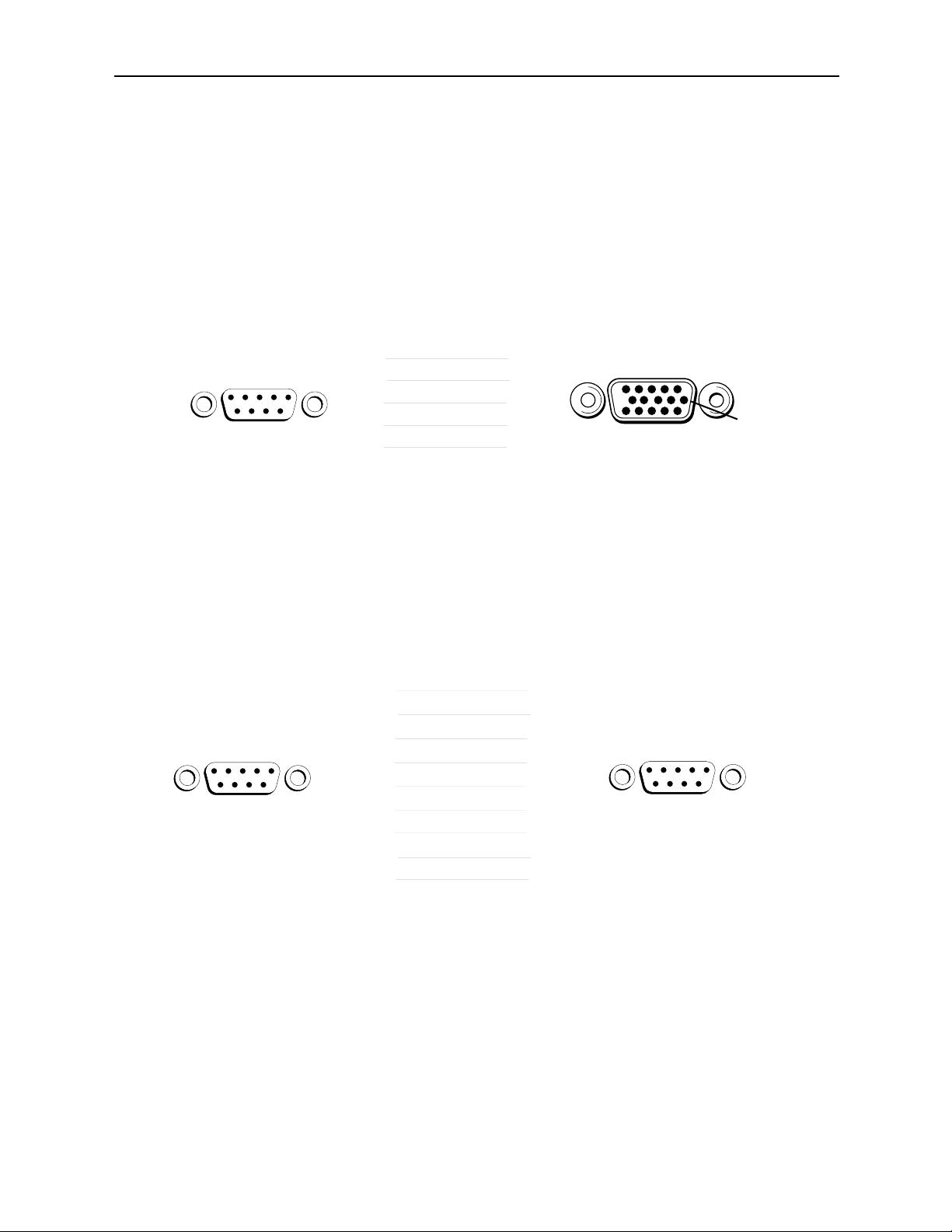
Avenue GPI Remote Control Panel
Connect an Avenue 5815 GPI Control Panel from the rear of the control panel (either
DB 9-pin male) to the Control connector on the rear of the 5420 module (HDB 15-pin
male). The pinout for this connecting cable is given below.
The 5815 GPI Control Panel can be rack-mounted in a standard 19 inch equipment
rack. Connect the universal in-line power supply provided to the connector at the left
rear of the GPI panel. The power supply is auto-sensing and requires no adjustments.
Up to eight Avenue 5815 GPI Control Panels can be connected in parallel for GPI
control. Panels are connected together via the DB 9-pin loop-through connectors on
each panel. The cable to connect each panel is a DB 9-pin male to DB 9-pin male with
straight pin-to-pin connections as shown in the illustration below. This cable may be
purchased at any electronics supply store or constructed from the diagram. Note not
all pins are necessary for control panel connection but all pins can be connected.
Model 5420 Digital Logo Inserter
Avenue GPI Remote Control Panel to Avenue Frame Pinout
Avenue GPI Remote Control Loop-through Pinout
5420-8
Avenue GPI
Control Panel
DB-9 Male
2
Pin 1
7
9
8
3
Avenue GPI
Control Panel
DB-9 Male
1
2
3
Pin 1
4
5
Pin 6
6
7
8
9
Only bolded pins are necessary
for control panel communication,
however, all pins may be connected.
5420 Control
HDB-15 Male
RX +
RX –
GND
TX –
TX +
Connector
1
2
3
4
5
1
2
3
4
5
6
7
8
9
Control
Avenue GPI
Control Panel
DB-9 Male
Pin 1
Pin 11
Pin 1
Pin 6
Pin 6Pin 6
Page 9

GPI Control
An external customer-supplied GPI device can be connected to the rear of the 5420
module to control any of the eight GPI inputs.
Connect the GPI control device to the 5420 Control connector pins as shown below.
Each GPI pushbutton should be wired with closure to ground to trigger a crosspoint.
Model 5420 Digital Logo Inserter
Customer-supplied GPI Device to Avenue Frame Pinout
5420-9
Customer -Supplied
GPI Device Switches
1
2
3
4
5
6
5420 Control
Connector
HDB-15 Male
15
14
12
11
10
9
Control
Pin 1
Pin 6
Pin 11
7
8
8
7
3, 6, 13
Page 10

5815 GPI Control Panel Operation
The GPI inputs to the 5420 module can control up to eight logos or animation sequences
defined as events using the remote control menus. The configured inputs can then be
triggered with the Avenue 5815 GPI Control Panel shown below. Up to eight control
panels can be installed in parallel as explained earlier in this data pack.
Assign logos or animation sequences to each of the eight GPI inputs using Avenue PC or
the Touch Screen control menus as explained in the next sections. When one of the eight
pushbuttons is selected, the event assigned to that input will be placed on air according to
the parameters (in and out transition time, density, horizontal and vertical position) configured with the remote control menus or with the Avenue Logo application.
Model 5420 Digital Logo Inserter
5815 GPI Control Panel
5420-10
Page 11

MODULE CONFIGURATION AND CONTROL
The configuration parameters for each Avenue module must be selected after installation.
This can be done remotely using one of the Avenue remote control options. This module
has no local front panel configuration controls. The REMOTE/LOCAL switch on the front
edge of the circuit board which should be set to the REMOTE mode.
The 5420 Parameter Table on the following page summarizes the various configuration
parameters that can be set remotely and the default/factory settings.
Avenue module parameters can be configured and controlled remotely from one or both of
the remote control options, the Avenue Touch Screen or the Avenue PC Application. Once
the module parameters have been set remotely, the information is stored on the module
CPU. This allows the module be moved to a different cell in the frame at your discretion
without losing the stored information. Remote configuration will override whatever the
switch settings are on the front edge of the module.
For setting the parameters using the Avenue PC option, refer to the Avenue PC Remote
Configuration section of this document.
For setting the parameters using the Avenue Touch Screen option, refer to the Avenue
Touch Screen operating section in the Avenue System Overview section.
Model 5420 Digital Logo Inserter
5420-11
Page 12

Model 5420 Digital Logo Inserter
5420-12
5420 Parameter Table
CONTROL LOCAL REMOTE DEFAULT
DEFAULT
USER LEVEL
Cut Off
On
Off
Off Level 2
Mix Off
On
Off
Off Level 2
Event Select 1 1 – 8 Event 1 Level 2
Number 1 1 – 50 Logo 1 Level 2
Density 100% 0 – 100% 100% Level 2
V Pos 0 lines 0 – 625 lines 0 lines Level 2
H Pos 0 pixels 0 – 720 pixels 0 pixels Level 2
Cycle Off
Off
Loop
Ping Pong
Off Level 2
Event No 1 Event 1 – 8 Event 1 Level 2
Enable 1
On
Off
On Level 2
Logo No 1 Logo 1 – 50 Logo 1 Level 2
In Trans 1 1 – 240 frames 1 Level 2
Out Trans 1 1 – 240 frames 1 Level 2
Mode DSK
DSK
DSK w/ Preview
Fill/ Key
DSK Level 2
GPI 8/Event 8 Event 8
Event 8
Mix
Cut
Event 8 Level 2
Ref Select Digital In
Digital In
External
Master
Digital In Level 2
Page 13

Front Panel Controls and Indicators
Each front edge indicator and switch setting is shown in the diagram below:
5420-13
Remote/Local switch:
Set to Remote mode only.
Pwr green LED:
Indicates the presence (ON) or
absence (OFF) of power (+5V).
Run green LED:
OFF:
A power fault or halted CPU
ON:
A halted CPU
FAST BLINK:
CPU Run error
SLOW BLINK:
System OK. (If SPI control is
active from the main frame
System Control Module, all
Run indicators will be synchronized.).
In OK green LED:
On when input deserializer is
locked to background serial input
signal.
OFF when input deserializer is not
locked to background serial input.
Model 5420 Digital Logo Inserter
Ref Lock green LED:
On when the reference is present.
Off when no reference is present.
Key On green LED:
On indicates when the key is on.
OFF indicates the key is off.
EDH Error
red LED:
On to indicate presence of EDH
errors in background serial input.
OFF when no EDH errors are
present in background serial input.
Page 14

Avenue PC Remote Configuration
The Avenue PC remote control status menus for this module are illustrated and explained
below. Refer to the 5420 Parameter Table for a summary of available parameters that
can be set remotely through the menus illustrated. For more information on using Avenue
PC, refer to the Avenue PC Control Application Software data pack that came with the
option.
Parameter fields that are grayed out can indicate one of the following conditions:
• An option is not installed.
• The function is not active.
• The module is locked.
• The User Level set with Avenue PC is not accessible from the current User Level.
For information on installing and using the Avenue Logo application for downloading logos
and animations to the module, refer to the Avenue Logo data pack and CD that accompanies the 5420 module.
5420 Avenue PC Menus
The Control menu screen shown below allows you to select an event defined in the Event
menu as the next transition.
• Cut – select to cut the selected event on or off.
• Mix – select to mix the selected event on or off.
• Event Select – select a defined event to be triggered by the corresponding GPI
input.
The following status display is provided:
• Status – shows the selected event status (Key Off and Key On).
5420-14
Model 5420 Digital Logo Inserter
Page 15

The Logo menu shown below allows you to select a logo, set up the density (transparency), select the type of cycling, and horizontal and vertical position of individual logos:
• Number – allows you to select the desired logo number stored in memory.
• Name – displays the name of the selected logo.
• Density – set the amount of transparency of the displayed logo.
• V Pos – set the vertical position of the logo in lines.
• H Pos – set the horizontal position of the logo in pixels.
• Cycle – select the type of cycle desired when an animation is enabled (Off, Loop
or Ping Pong).
The following status display is provided:
• Name – displays the name of the currently selected logo.
• Type – displays the type of logo (Still or Animation).
Note: When you change parameters for a logo with these local controls, you may wish to
note the changes for each logo. As these changes are not reflected back to the original file
stored on the PC, you can then make these changes to the file stored in the project folder
with Avenue Logo. The next time you download the logo it will not need any adjustment.
Model 5420 Digital Logo Inserter
5420-15
Page 16

Model 5420 Digital Logo Inserter
The Event menu shown below allows you to define an event:
• Event No – select an event number to define (1 – 8).
• Logo No – select the logo number you wish to include in the event.
• In Tran – set the transition time in frames for the logo to key on.
• Out Tran –set the transition time in frames for the logo to key off.
• Enable – check the On box to enable the defined event.
5420-16
Page 17

The Config menu shown below allows you to configure the mode, the GPI 8 control
action, and the reference input for the module:
• Mode – select either DSK, DSK w/Preview, or Fill/Key mode for the module.
• GPI 8/Event 8 – select the action for the GPI 8 control as fire Event 8, or Mix or
Cut the selected Event 1 – 7, On, or Off.
• Ref Select – choose a reference source from Digital In, External, or Master
when Fill/Key mode is selected.
The following status displays are also provided:
• Input Status – displays the status of the serial digital input signal as No Input
and Input OK.
• EDH Status – displays the EDH status of the digital input signal (No Input, No
EDH, EDH OK, or EDH Error).
• Reference – displays the selected reference when in Fill/Key mode (525, 625 or
No Ref).
Model 5420 Digital Logo Inserter
5420-17
Page 18

Model 5420 Digital Logo Inserter
Avenue Touch Screen Remote Configuration
The Avenue Touch Screen remote control status menus for this module are illustrated and
explained below. Refer to the 5420 Parameter Table for a summary of available parameters that can be set remotely through the menus illustrated. For more information on
using Avenue Touch Screen, refer to the Avenue System Overview operating section.
Parameter fields that are grayed out can indicate one of the following conditions:
• An option is not installed.
• The function is not active.
• The module is locked.
• The User Level set with Avenue PC is not accessible from the current User Level.
For information on installing and using the Avenue Logo application for downloading logos
and animations to the module, refer to the Avenue Logo data pack and CD that accompanies the 5420 module.
5420 Avenue Touch Screen Menus
The Control menu screen shown below allows you to select an event defined in the Event
menu as the next transition.
• Cut – select to cut the selected event on or off.
• Mix – select to mix the selected event on or off.
• Event Select – select a defined event to be triggered by the corresponding GPI
input.
The following status display is provided:
• Status – shows the selected event status (Key Off and Key On).
5420-18
Page 19

The Logo menu shown below allows you to select a logo, set up the density (transparency), select the type of cycling, and horizontal and vertical position of individual logos:
• Number – allows you to select the desired logo number stored in memory.
• Name – displays the name of the selected logo.
• Density – set the amount of transparency of the displayed logo.
• V Pos – set the vertical position of the logo in lines.
• H Pos – set the horizontal position of the logo in pixels.
• Cycle – select the type of cycle desired when an animation is enabled (Off, Loop
or Ping Pong).
The following status display is provided:
• Name – displays the name of the currently selected logo.
• Type – displays the type of logo (Still or Animation).
Note: When you change parameters for a logo with these local controls, you may wish to
note the changes for each logo. As these changes are not reflected back to the original file
stored on the PC, you can then make these changes to the file stored in the project folder
with Avenue Logo. The next time you download the logo it will not need any adjustment.
Model 5420 Digital Logo Inserter
5420-19
Page 20

The Event menu shown below allows you to define an event:
• Event No – select an event number to define (1 – 8).
• Logo No – select the logo number you wish to include in the event.
• In Tran – set the transition time in frames for the logo to key on.
• Out Tran –set the transition time in frames for the logo to key off.
• Enable – check the On box to enable the defined event.
Model 5420 Digital Logo Inserter
5420-20
Page 21

The Config menu shown below allows you to configure the mode, the GPI 8 control action,
and the reference input for the module:
• Mode – select either DSK, DSK w/Preview, or Fill/Key mode for the module.
• GPI 8/Event 8 – select the action for the GPI 8 control as fire Event 8, or Mix or
Cut the selected Event 1 – 7, On, or Off.
• Ref Select – choose a reference source from Digital In, External, or Master
when Fill/Key mode is selected.
The following status displays are also provided:
• Input Status – displays the status of the serial digital input signal as No Input
and Input OK.
• EDH Status – displays the EDH status of the digital input signal (No Input, No
EDH, EDH OK, or EDH Error).
• Reference – displays the selected reference when in Fill/Key mode (525, 625 or
No Ref).
Model 5420 Digital Logo Inserter
5420-21
Page 22

TROUBLESHOOTING
As a troubleshooting aid, the reference signal status and presence, power and CPU status
can be easily monitored from the front panel of this module using the front panel indicators.
Refer to the overall troubleshooting tips given below for the module:
Can’t control module:
• Check status of CPU Run green LED. Should be blinking slowly and in
unison with other modules if System module is present. If not, try removing
it and plugging it in again to be sure it is seated properly.
• System module may not be working properly if installed.
• Front panel Local/Remote switch not in Remote when using Avenue PC.
No signal out of module:
• Check status of In OK LED.
• Check cabling to input of module.
You may also refer to the technical support section of the Ensemble Designs web site for
the latest information on your equipment at the URL below:
http://www
.ensembledesigns.com/support
SOFTWARE UPDATING
Software upgrades for each module can be downloaded remotely if the optional System
Control module is installed. These can be downloaded onto your PC and then Avenue PC
will distribute the update to the individual module. (Refer to the Avenue PC documentation for more information) Periodically updates will be posted on our web site. If you do
not have the required System Control Module and Avenue PC, modules can be sent back
to the factory for software upgrades.
Model 5420 Digital Logo Inserter
5420-22
Page 23

5420-23
Model 5420 Digital Logo Inserter
WARRANTYAND FACTORY SERVICE
Warranty
This module is covered by a five year limited warranty, as stated in the main Preface of
this manual. If you require service (under warranty or not), please contact Ensemble
Designs and ask for customer service before you return the unit. This will allow the
service technician to provide any other suggestions for identifying the problem and
recommend possible solutions.
Factory Service
If you return equipment for repair, please get a Return Material Authorization Number
(RMA) from the factory first.
Ship the product and a written description of the problem to:
Ensemble Designs, Inc.
Attention: Customer Service RMA #####
870 Gold Flat Rd.
Nevada City, CA. 95959 USA
(530) 478-1830
Fax: (530) 478-1832
service@endes.com
http://www.ensembledesigns.com
Be sure to put your RMA number on the outside of the box.
Page 24

5420-24
SPECIFICATIONS
5420 Digital Logo Inserter
Input Signal:
Number: One
Signal Type: Serial Digital (SMPTE 259M)
Impedance: 75 Ω
Return Loss: > 15 dB DC to 270 Mbs
Maximum Cable
Loss: 300 meters of Belden 8281
Reference Input Signal:
Number: One external (Master)
One internal (External)
Signal Type: 1 V p-p nominal composite video, PAL or NTSC
Return Loss: > 40 dB (applies to external reference input)
Serial Outputs 1 – 4:
Signal Type: Serial Digital (SMPTE 259M)
Impedance: 75 Ω
Return Loss: > 15 dB DC to 270 Mbs
Output DC: None (AC coupled)
Delay: < 30 clocks from Background input
Reclocked Loop Through Signal:
Number: One
Signal Type: Serial Digital (SMPTE 259M)
Impedance: 75 Ω
Return Loss: > 15 dB DC to 270 Mbs
Output DC: None (AC coupled)
Delay: ~ 2 clocks
General Specifications:
Connectors: BNC
Power Consumption: < 9.6 Watts
Temperature Range: 0 to 50 degrees C ambient (all specs met)
Relative Humidity: 0 to 95% noncondensing
Altitude: 0 to 10,000 ft
Fusing: 1.5 Amp PTC resettable fuse
Due to ongoing product development, all specifications subject to change.
Model 5420 Digital Logo Inserter
Page 25

APPENDIX A
Serial Control
The 5420 Digital Logo Inserter module has a serial interface port which supports a
command protocol for remote control of the eight GPI selections. This serial port is used
by the optional Avenue 5815 GPI Control Panel or an external GPI control device. The
port can also be used by external devices such as a PC to control the GPI inputs.
Refer to the pinout information in the illustration below for the cable needed to connect a
PC or other device to the serial port of the module. The port can be cabled to support
either RS-422 or RS-232 signaling levels.
The details for the serial protocol are outlined in the section below.
The communication standard for this port is as follows:
Data Rate: 38.4 Kbaud
Start Bits: 1
Stop Bits: 1
Parity: None
The command and status messages for this port are in plain ASCII form, with each
command or message terminated with a carriage return (shown as <cr> below).
Commands to the module are as follows:
Fire GPI Command
Syntax: G1 <cr>
This will fire GPI 1.
The module will respond with a single status message:
Syntax: S1 <cr>
Model 5420 Digital Logo Inserter
External Serial Control to Avenue Frame Control Cable Pinout
5420-25
External Serial
Control Device
DB-9 Male
3
Pin 1
2
5
TX
RX
GND
5420 Control
Connector
HDB-15 Male
2
4
1, 9
Control
Pin 1
Pin 11
Pin 6Pin 6
Page 26

Model 5420 Digital Logo Inserter
5420-26
 Loading...