

Page 1
This data pack provides detailed installation, configuration and operation information for
the 5400 Dual Sync Generator and Test Signal Generator as part of the Avenue
Signal Integration System.
The module information in this data pack is organized into the following sections:
• Module Overview
• Applications
• Installation
• Cabling
• Module Configuration and Control
°
Front Panel Controls and Indicators
°
Avenue PC Remote Control
°
Avenue Touch Screen Remote Control
• Troubleshooting
• Software Updating
• Warranty and Factory Service
• Specifications
5400-1
Model 5400
Dual Sync Generator
and Test Signal
Generator
Data Pack
ENSEMBLE
DESIGNS
Revision 5.1 SW v2.0
Page 2

MODULE OVERVIEW
The 5400 module is a stable timing source suitable for local reference generation for use
in broadcast, remote trucks and post-production. Dual outputs, available simultaneously
in analog composite and serial digital and an HD tri-level sync reference output are
provided. In addition, more than twenty internally-generated test signals, including black
and color bars, and EDH Error generation are available.
The 5400 can operate from an internal precision frequency reference as a stand alone
master sync generator or lock to a video reference from an external source. The module
can also lock to an external 10 MHz source such as an atomic standard or GPS receiver
for more precision.
Two sets of composite outputs and serial outputs are provided. One serial output together
with a pair of composite outputs form the primary sync generator. A second serial output
together with an associated pair of composite outputs form a separate secondary sync
generator.
The test signal generator is always output to the primary outputs. An ID slate with user
programmable text can be overlayed on the test pattern. The secondary sync generator
always outputs color black.
The Primary and Secondary outputs can be timed with respect to the reference to any
point in the television frame. Color framing tracks the reference signal. Timing adjustments for primary and secondary outputs are configured independently and the 5400 can
be configured to output 525 and 625 standards simultaneously.
An optional submodule, the 5410, can be installed to provide audio test signals, AES3id,
word clock or 6 Hz output, analog tone and embedded audio reference outputs. The AES
outputs are synchronous to the 525 and 625 outputs as they share the same time base.
The Primary 601 output will have EDH checksums inserted.
Another feature available when the 5410 submodule is installed is the Make EDH Error
function which deliberately introduce different types of errors in the Primary SDI output.
EDH (Error Detecting and Handling) is a method to detect and indicate loss of data path
integrity and corruption. A CRC (Cyclic Redundancy Character) checksum is computed at
the point of transmission and inserted in a special data packet in the vertical interval of
the signal. At downstream locations, this CRC can be recovered and checked against a
value which has been locally re-computed from the same video data stream. If the transmitted CRC and the re-computed CRC values match, there have been no errors in transmission.
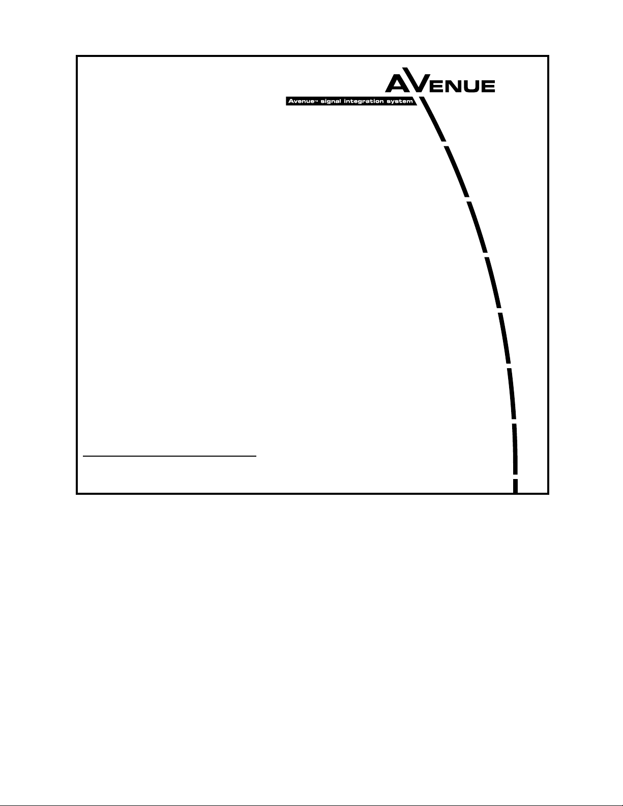
As shown in the block diagram on the following page, the time base reference is selected
from either the Master or Genlock (external) reference. The selected reference passes
through a precision sync separator to derive the required sync components. The separated
sync signal provides the timing reference for the PLLs.
These primary timing signals then pass through timing adjustment and burst detection
circuitry to determine color field sequence. They are then used to generate the test signal
pattern and black test signals in their respective generators. The test signals pass to the
Primary and Secondary serial outputs and also enter composite encoders to provide the
Primary and Secondary composite analog outputs.
Model 5400 Dual Sync Gen/Test Signal Generator
5400-2
Page 3
Model 5400 Dual Sync Gen/Test Signal Generator
The Tri-Level Sync output is analog timing reference intended for use with high definition
equipment. It uses the same time base as the Primary sync generator and can be framesynchronized when their output standard match.
If the optional 5410 submodule is installed, the reference signal passes to the submodule
where an AES tone and word clock are derived. This audio information can be embedded
into Group 1 of the Primary serial output and also passes to the output BNCs as the
audio references. It is also sent to a D-to-A converter where it is converted to analog
composite audio and feeds the rear Audio Out 15-pin connector.
Test patterns can be overlayed with an ID slate configurable in the remote Avenue PC or
Touch screen option interfaces. The slates can also be enabled by remote control with GPI
closures accessible from the 15-pin Audio Out connector.
A special feature that adds motion to the test signal can also be inserted along with the
Slate ID or, independently of it. This feature, called Cyclops, indicates true frame motion
from the test signal with an on-screen indicator that moves from side to side. It can
indicate whether the signal is live or has frozen, such as when a frame synchronizer loses
it input and freezes. Additionally, audio left and right channel indicators can be enabled to
synchronize with the Cyclops to verify audio connectivity and timing.
Power is derived from the ± 12 volt frame power. It is regulated to the required +5 volts
for the module by on-board regulator. The module is fused with a resettable fuse device. If
the fuse opens due to an overcurrent condition, the module will lose power. After pulling
the module, the fuse will reset automatically requiring no replacement fuse.
5400-3
5400 Dual Sync Generator and TSG Block Diagram
Video Genlock/
10 MHz (GPS)
Master
Frame
Ref
Precision
Standard
Internal
Sync
Detector
Timing
Adj
PLL
PLL
Timing
Adj
Test Signal
Gen
AES Tone
& Word Clock
Black
Gen
Audio
Embed
Gen
HD Tri-Level
Sync Gen
Composite
Encoder
Serializer
24 Bit
2 Channel
D to A
5410 Option
Composite
Encoder
Serializer
Jumper J3
Tri-Level
Sync Out
Primary Out
Composite
Analog
Serial
Digital
Analog
L
Tone
Out
R
AES
AES/WC
Secondary Out
Composite
Analog
Serial
Digital
Page 4
Model 5400 Dual Sync Gen/Test Signal Generator
5400-4
The on-board CPU can monitor and report module ID information (slot location, software
version and board revision), and power status to the optional frame System Control
module. This information can be accessed by the user or set to register an alarm if desired
using the remote control options available.
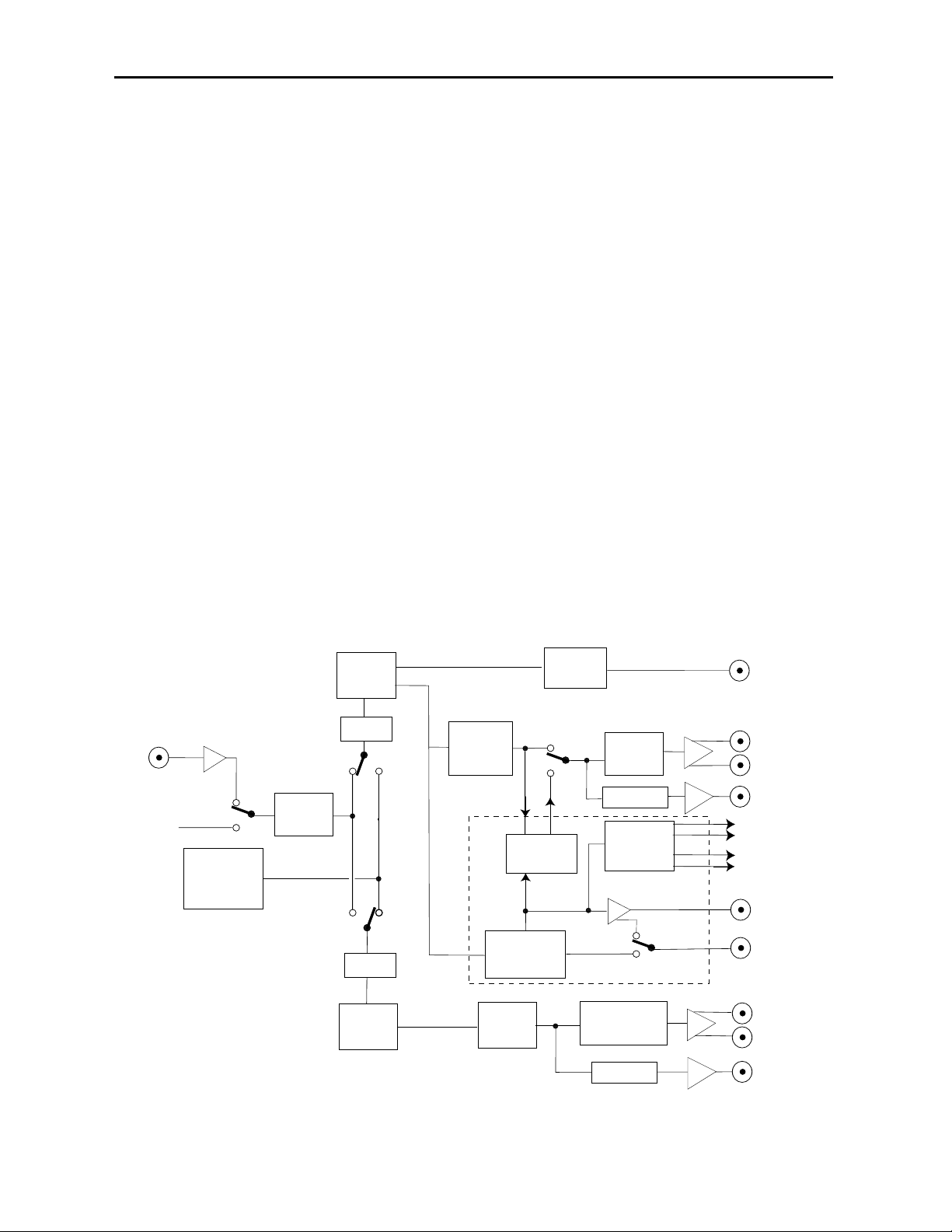
APPLICATIONS
Simultaneous References
As shown in the application below, the 5400 module can provide simultaneous 525, 625
and AES reference outputs, all derived from the same time base, all from the same
module.
Digital, Analog and Audio Reference Generation and Distribution
Another application shown below, illustrates how the 5400 module can provide digital,
analog and audio reference outputs which can then be distributed throughout a facility
when combined with the 5125 Dual DA and the 5150 DA. Audio reference signals are
available when the 5410 submodule is installed.
5400 Providing Simultaneous Reference Outputs
5400 Providing Digital, Analog and Audio Reference Outputs
601
Primary
Composite
Composite
525
5400
Secondary
5410
601
Composite
Composite
Audio
625
AES
AES with WC
Analog Tone
601
601
Composite
Composite
5125
Dual DA
5150 DA
601 (x4)
601 (x4)
Composite (x9)
5400
Primary
Secondary
Primary
Secondary
5410
AES Reference
5150 DA
5150 DA
Composite (x9)
AES Reference (x9)
Page 5
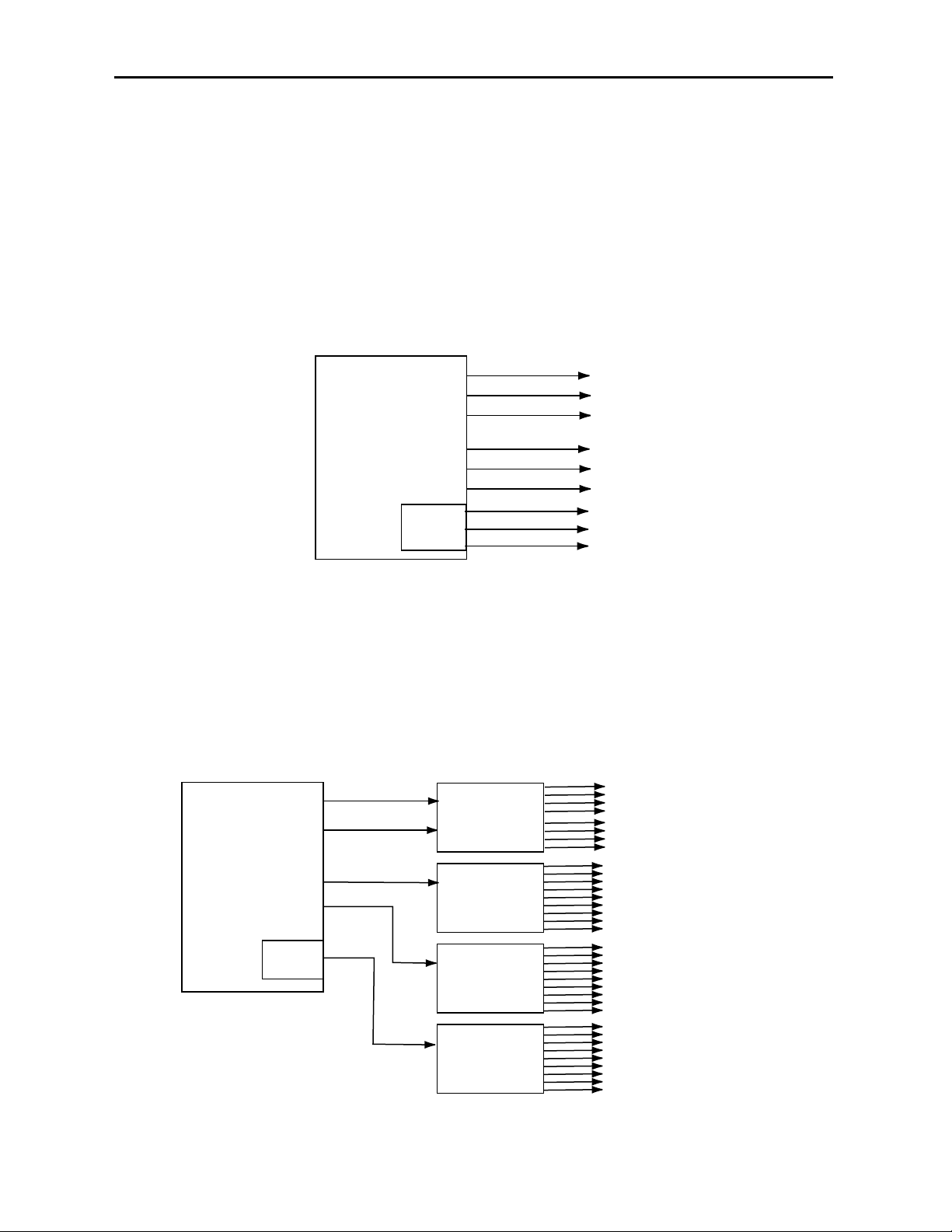
Analog Composite References
Another application for the 5400 is to combine it with the 5405, a Dual Analog Sync
Generator, to output a set of independently timed composite outputs to provide a master
genlock reference for an entire facility. As shown below, the 5400 Primary and Secondary
analog composite outputs feed Master Control destinations and the 5405 which is then
sent to other facility locations.
5400-5
Model 5400 Dual Sync Gen/Test Signal Generator
5400 With 5405 Providing Composite Reference Outputs
Plant Master
Generator
Primary
5400 Dual
Sync Gen/TSG
Secondary
Out 1
Out 2
Master Control 1
Master Control 2
5405 Dual
Genlock
Analog
SPG
Out 3
Out 4
Studio A
Studio B
Page 6
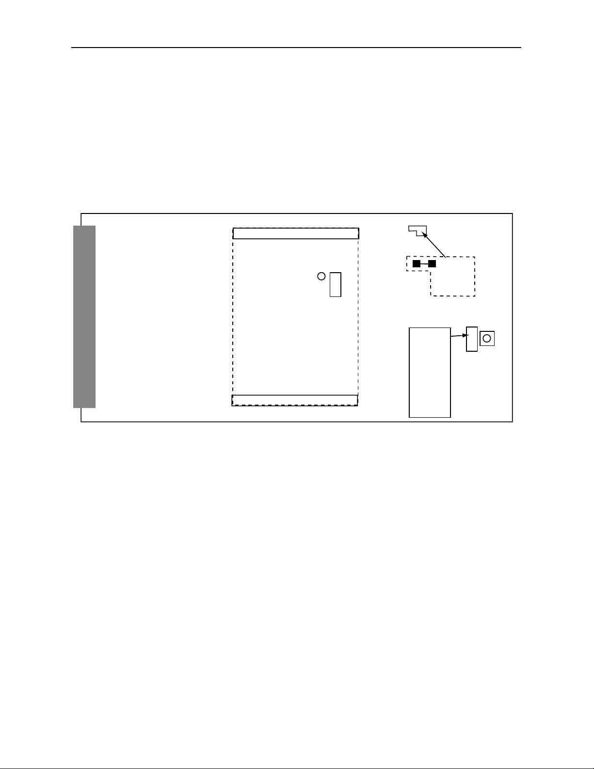
INSTALLATION
Local Setup
If you will be using the module in Local mode, you will need to use the rotary switch
shown in the figure below to select the test pattern. Make your test pattern selection from
the choices shown. Refer to Appendix A for test pattern descriptions. (In older module
versions, the rotary switch is located under the 5410 submodule).
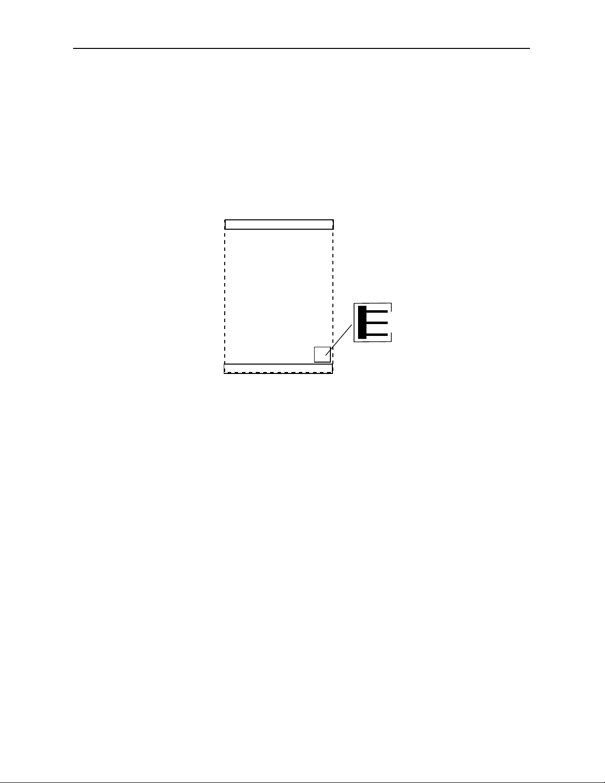
Local Mode Setup Removal: A setup removal jumper is provided for removing setup in
Local mode when operating in 525/60 Hz mode. To remove setup, cut the trace connecting
the two sides of R175 as shown below. In remote mode this is not required.
Model 5400 Dual Sync Gen/Test Signal Generator
5400-6
Local Mode 5400 Setup
Location of rotary switch
in older modules
5410 Submodule
R175
REMOVE
SHORT FOR
NO SETUP
Test Pattern Select
Rotary Switch
SW POS
0 — BLK
1 — BARS
2 — BARS
3 — WIND
4 — RAMP
5 — SWEEP
6 — COSITE
7 — PATH
8 — SAFE
9 — MULTI
Page 7
5410 Submodule
Install the 5410 submodule by lining up the connectors on the submodule with the connectors on the 5400 module. The connector is keyed to prevent installing it incorrectly.
AES B Out Jumper
A jumper, AES B OUT, J3, on the 5410 submodule (shown below) allows the user to select
the type of audio output on the AES Out 2/Wordclock BNC on the rear of the module.
When AES is selected, the output will be an AES3id signal from the BNC. Setting J3 to
WD_CLK, allows either a Wordclock output or a 6 Hz 4.5 align pulse, used in telecine
applications. When set to WD-CLK, the pulse type must be selected in the Pulse Select
pulldown in the Avenue PC or Touch Screen Config menu.
5400 Module
Plug the 5400 module into any one of the slots in the 3 RU frame and any slot except Slot
3 in the 1 RU frame. Install the plastic overlay provided onto the corresponding group of
rear BNC connectors associated with the module location. Note that the plastic overlay
has an optional adhesive backing for securing it to the frame. Use of the adhesive backing
is only necessary if you would like the location to be permanent and is not recommended if
you need to change module locations. This module may be hot-swapped (inserted or
removed) without powering down or disturbing performance of the other modules in the
system.
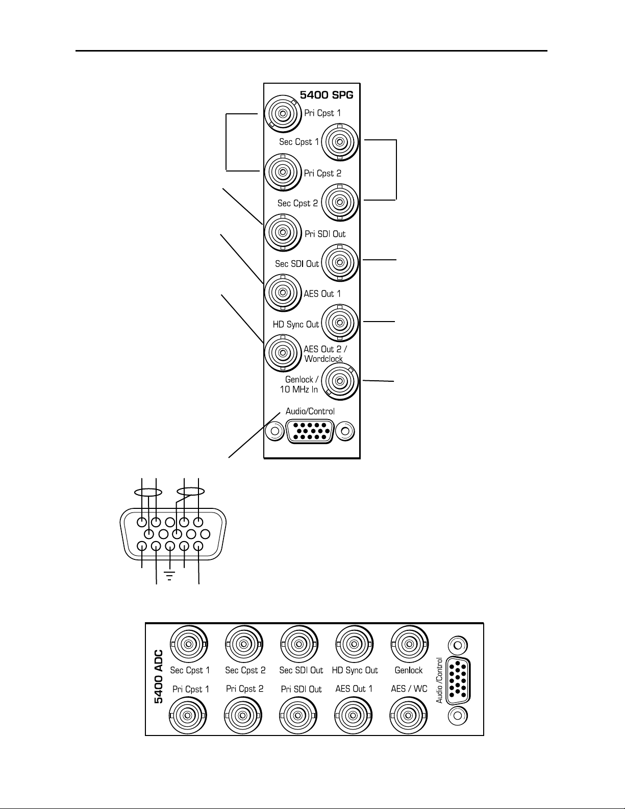
CABLING
Refer to the 3 RU and 1 RU backplane diagrams of the module on the next page for
cabling instructions. Note that unless stated otherwise, the 1 RU cabling explanations are
identical to those given in the 3 RU diagram.
Model 5400 Dual Sync Gen/Test Signal Generator
5400-7
5410 Jumper Setting
5410 Submodule
J3 AES B OUT
WD_CLK
AES
Page 8
Model 5400 Dual Sync Gen/Test Signal Generator
3 RU Backplane
Connect the Pri Cpst 1
and Pri Cpst 2 output
BNCs to composite
analog destinations.
Connect the Sec Cpst 1
and Sec Cpst 2 output
BNCs to composite
analog destinations.
Connect the Pri SDI Out
BNC to a serial digital
destination.
Connect the AES Out 1
BNC an AES audio destination. (5410 submodule
required.)
Connect the AES Out 2/
Wordclock BNC to an AES
audio or wordclock destination (5410 submodule
required).
NOTE: To enable the
Wordclock output, jumper J3
on the 5410 submodule must
be set to WD_CLK. Use the
Pulse Select pulldown in the
Config menu to set the pulse
type to Wordclock or a 6 Hz
pulse.
5400-8
Connect the Sec SDI
Out BNC to a serial
digital destination.
Connect the HD Sync
Out BNC to a high definition destination.
Connect an NTSC/PAL or 10
MHz input signal to the
Genlock/10 MHz In BNC to
provide the external genlock
reference.
With the 5410 submodule installed, you can access the CH A
and CH B analog tone outputs according to the pinout at left.
You may connect an external device to the GPI inputs at pins
11, 12, 14 and 15 of the Audio Out connector to remotely
control one of four slates.
There are two channels of audio. Channel Ais on pins 1 and
2 and the associated ground is pin 8. Pin 1 is positive.
Channel B is on pins 4 and 5 and the associated ground is on
pin 10. Pin 5 is positive.
1 RU
Backplane
CH B
+
GPI
4
-
GPI
3
CH A
-
GPI
2
+
GPI
1
1
6
11
Page 9

MODULE CONFIGURATION AND CONTROL
The configuration parameters for each Avenue module must be selected after installation.
This can be done remotely using one of the Avenue remote control options or locally using
the module front panel controls. Each module has a REMOTE/LOCAL switch on the
front edge of the circuit board which must first be set to the desired control mode.
The configuration parameter choices for the module will differ between Remote and
Local modes. In Remote mode, the choices are made through software and allow more
selections. The 5400 Parameter Table on the following page summarizes and compares
the various configuration parameters that can be set remotely or locally and the
default/factory settings. It also provides the default User Levels for each control. These
levels can be changed using the Avenue PC application.
If you are not using a remote control option, the module parameters must be configured
from the front panel switches. Parameters that have no front panel control will be set to a
default value. The Local switches are illustrated in the Front Panel Controls and
Indicators section following the 5400 Parameter Table.
Avenue module parameters can be configured and controlled remotely from one or both of
the remote control options, the Avenue Touch Screen or the Avenue PC Application. Once
the module parameters have been set remotely, the information is stored on the module
CPU. This allows the module be moved to a different cell in the frame at your discretion
without losing the stored information. Remote configuration will override whatever the
switch settings are on the front edge of the module.
For setting the parameters remotely using the Avenue PC option, refer to the Avenue PC
Remote Configuration section of this document.
For setting the parameters remotely using the Avenue Touch Screen option, refer to the
Avenue Touch Screen Remote Configuration section of this data pack following
Avenue PC.
Model 5400 Dual Sync Gen/Test Signal Generator
5400-9
Page 10
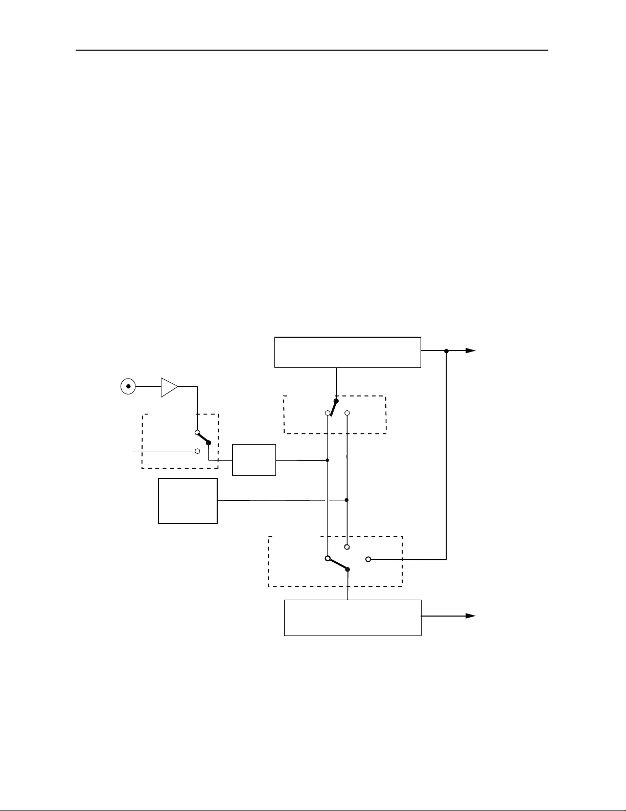
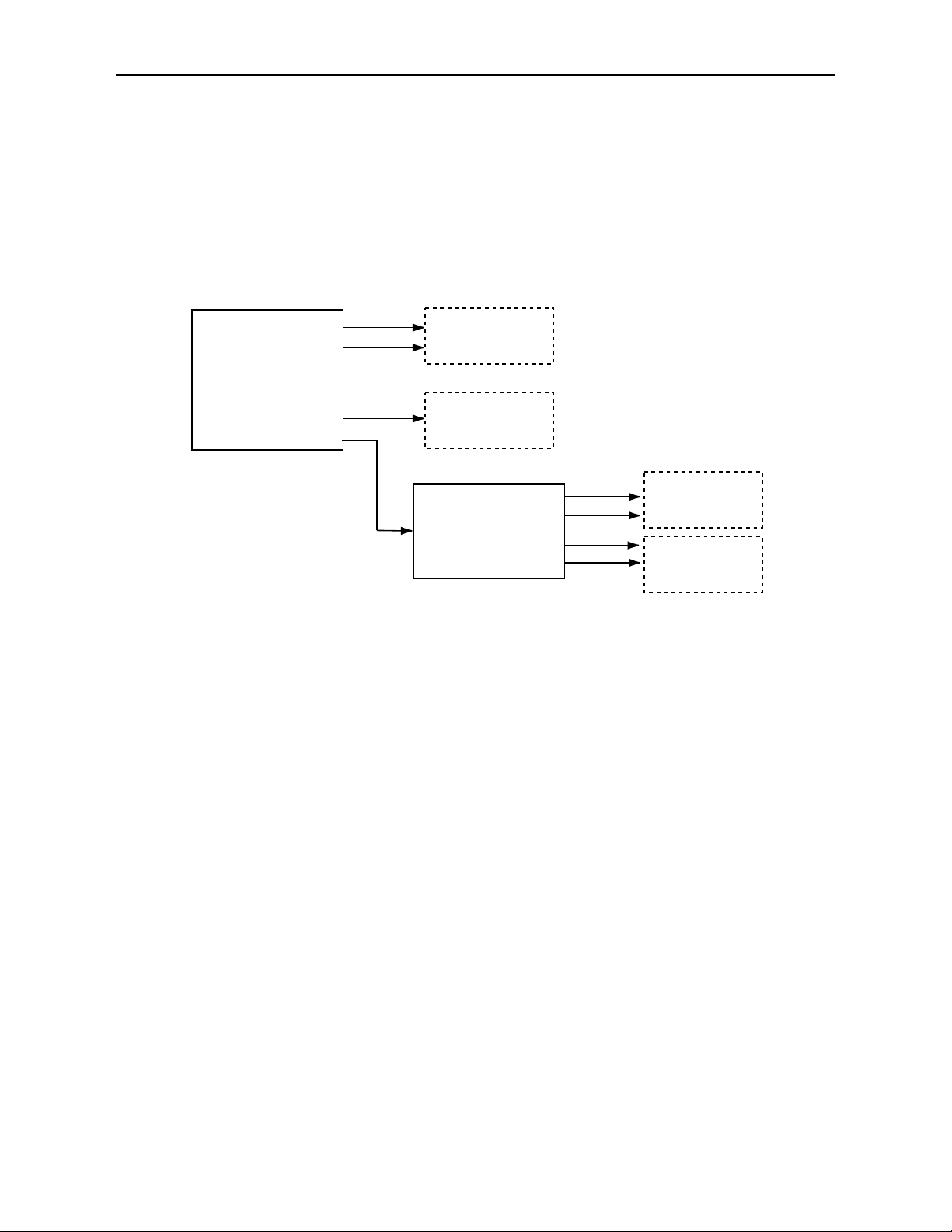
Making Reference Choices
Each generator can be independently set to operate either as a Master Sync Generator
(using an internal precision frequency reference), or genlocked to an external reference
source of either composite video or a 10 MHz sine or square wave. In addition, the
secondary generator can be set to lock to the primary generator in tracking mode. These
choices are made using the Pri and Sec Source controls in the Primary and Secondary
menus. Refer to the block diagram below.
When a generator is set to be genlocked (by selecting Config Ref in the Pri or Sec
Source menu), a further selection must be made to configure the module to use either its
external genlock BNC (labeled Genlock/10 Mhz In on the module backplane) or the
Master Frame Reference which is distributed through the Avenue frame backplane. This
choice is made in the Config menu and provides the configured reference for both generators. The module will accept analog composite NTSC (525) or PAL (625), or a 10 MHz sine
or square wave as an external genlock signal.
In order to provide the ultimate in flexibility, the television line standard output for each
generator can then be set to either 525/60 Hz or 625/50 Hz. These output choices are
possible even when the generators are locked to a genlock input in a different standard.
5400-10
Model 5400 Dual Sync Gen/Test Signal Generator
Primary and Secondary Reference Source Detail
Genlock/10 MHz
Config Ref
Ext Video
Master
Frame
Ref
Master
Internal
Precision
Standard
Sync
Detector
Primary Generator
Pri Source
Config
Ref
Sec Source
Config
Ref
Secondary Generator
525/60 Hz
or
625/50 Hz
Internal
Internal
Track
Primary
525/60 Hz
or
625/50 Hz
Page 11
Model 5400 Dual Sync Gen/Test Signal Generator
5400-11
5400 Parameter Table
CONTROL LOCAL REMOTE DEFAULT
DEFAULT
USER LEVEL
Primary Source
Switch 1:
Internal
GL
Internal
Config Ref
Config Ref Admin
Primary Standard
Switch 2:
525
625
525 – 60 Hz
625 – 50 Hz
525 – 60 Hz Admin
Setup
N/A On
Off
On
User 2
Secondary Source
N/A Internal
Config Ref
Track Primary
Config Ref Admin
Secondary Standard
Switch 4:
525
625
525 – 60 Hz
625 – 50 Hz
525 – 60 Hz Admin
Setup
N/A On
Off
On
User 2
Pattern Type
(2 pulldown choices)
Rotary Switch:
0 Black
1 SMPTE 75%
2 Split Field 75%
3 Window
4 Video Ramp
5 Sweep w/Fdl Mrkrs
6 Cosite
7 Pathological
8 SafeTitle
9 Multipattern
Bars –
Split Field 75
Split Field 100
SMPTE 75
SMPTE 100
Full Field 75
Full Field 100
Black –
Black
Flat Field 50
Flat Field 80
White
Ramp –
Video Ramp
Data Ramp
Shallow
5 Step
DAC Test
Sweep –
w/Markers
Full Field
Multiburst
Pulse & Bar –
Window
Full Field
Component
Window 100
Window 20
Timing –
Analog Blanking
Digital Blanking
Cosite
Interlace
BowTie
Misc –
Black
Crosshatch
Safe Title
Unit Circle
Multi Pattern
Multi Cpst
Pathological
16 by 9
Bars Admin
Page 12

5400 Parameter Table (Con’t)
Model 5400 Dual Sync Gen/Test Signal Generator
5400-12
CONTROL LOCAL REMOTE DEFAULT
DEFAULT
USER LEVEL
Y/Cr/Cb Channel
Enable
N/A On
Off
On User 1
Audio Select
N/A Tone
Pop
Beep
Silent
Tone User 2
Embed
Switch 3:
Embed Tone
No Tone
On
Off
On
User 2
Slate Select
N/A Off
Slate 1
Slate 2
Slate 3
Slate 4
GPI Low
GPI High
Off User 2
Cyclops
N/A On
Off
Off User 2
Pri Vert Timing
N/A ± 525 lines 0 lines User 2
Pri Horiz Timing
N/A ± 1716 clocks 0 clocks User 2
Pri Fine Phase
N/A ± 35 nsec 0 nsec User 2
Pri Color Frame
N/A Normal
Field 3
Field 5
Field 7
Normal User 2
Sec Vert Timing
N/A ± 525 lines 0 lines User 2
Sec Horiz Timing
N/A ± 1716 clocks 0 clocks User 2
Sec Fine Phase
N/A ± 35 nsec 0 nsec User 2
Sec Color Frame
N/A Normal
Field 3
Field 5
Field 7
Normal User 2
HD Standard
Switch 5:
1080
720p
Switch 6:
1080i
1080sf
720p/50 Hz
720p/59.94 Hz
720p/60 Hz
1080i/50 Hz
1080i/59.94 Hz
1080i/60 Hz
1080p/23.98 Hz
1080p/24 Hz
1080p/25 Hz
1080sf/23.98 Hz
1080sf/24 Hz
1080sf/25 Hz
1080i/59.94 Hz User 2
HD Vert Timing
N/A ± 1125 lines 0 lines User 2
HD Hor Timing
N/A ± 688 lines 0 lines User 2
Config Ref
N/A Ext Video
Master Ref
Ext Video User 2
Page 13

5400 Parameter Table (Con’t)
CONTROL LOCAL REMOTE DEFAULT
DEFAULT
USER LEVEL
Pulse Select
N/A AES Word Clock
6 Hz 4:5 Align
AES Word Clock User 2
Make EDH Error
N/A No Errors
AP CRC Error
FF CRC Error
AP EDH Error
FF EDH Error
AP EDA Error
FF EDA Error
No Errors User 2
AES Ref Level
N/A -20 dB
-18 dB
-20 dB User 2
Analog Ref Level
N/A -10 dB
-6dB
-4 dB
0 dB
+4 dB
+8 db
AES Word Clock User 2
Model 5400 Dual Sync Gen/Test Signal Generator
5400-13
Page 14

Front Panel Controls and Indicators
Each front edge indicator and switch setting is shown in the diagram below:
5400-14
Remote/Local switch:
Set to the mode you
will be using.
Pwr green LED:
Indicates the presence (ON) or
absence (OFF) of power (+5V).
Run green LED:
OFF:
A power fault or halted CPU
ON:
A halted CPU
FAST BLINK:
CPU Run error
SLOW BLINK:
System OK. (If SPI control is
active from the main frame
System Control Module, all
Run indicators will be synchronized.).
Ref 525, 625 and 10 MHz
green LEDs:
One LED will light to indicate
which reference rate is currently
being detected.
OFF when rate is not detected.
Pri 525/625
green LEDs:
One LED will light to indicate
the Primary output line standard
and that it is locked to its timing
source.
If no LED is lit, the Primary
generator is not locked to its
timing source.
Model 5400 Dual Sync Gen/Test Signal Generator
Sec 525/625 green LEDs:
One LED will light to indicate
the Secondary output line
standard and that it is locked to
its timing source.
If no LED is lit, the Secondary
generator is not locked to its
timing source.
Error red LED:
Indicates a genlock or
synchronization problem.
Ref (Reference)
Internal/GL
switch:
Set the reference source to Internal
(left) or GL, Genlock, (right) if using
the external reference input as the
timing source.
Pri (Primary Generator)
525/625
switch:
Set the Primary output line rate to
525 (left) or 625 (right).
Aud Insert
switch:
Set the switch to On (left) to embed
an audio tone into the Primary serial
output or Off (right) for no tone
Sec (Secondary Generator)
525/625
switch:
Set the Secondary generator output
line rate to 525 (left) or 625 (right).
HD (High Definition)
1080/720p
switch:
Set to either 1080 (left) or 720p
(right) for the type of tri-level HD
sync output desired.
1080i/sF
switch:
For 1080 signals, select either
1080i (left) for interlaced or 1080sF
(right) for segmented frame.
(Note: The frame rate will match the
Primary.)
Page 15

Avenue PC Remote Configuration
The Avenue PC remote control status menu for this module is illustrated and explained
below. Refer to the 5400 Parameter Table for a summary of available parameters that
can be set remotely through the menus illustrated. For more information on using Avenue
PC, refer to the Avenue PC Control Application Software data pack that came with the
option.
Parameter fields that are grayed out can indicate one of the following conditions:
• An option is not installed.
• The function is not active.
• The module is locked.
• The User Level set with Avenue PC is not accessible from the current User Level.
5400 Avenue PC Menus
The Primary menu screen shown below allows you to set the following parameters for the
Primary generator output:
• Pri Source – select the Primary generator reference source from either Config
Ref (as defined in the Config menu) or Internal.
• Standard – select the desired line standard output from 525–60 Hz or 625–50 Hz.
• Setup – sets setup to On or Off for 525–60 Hz line output signals.
The Sync Lock window shows what standard the module is locked to or No Lock.
5400-15
Model 5400 Dual Sync Gen/Test Signal Generator
Page 16

The Secondary menu screen shown below allows you to set the following parameters for
the Secondary generator output:
• Sec Source – select the Secondary generator reference source from either Config
Ref (defined in the Config menu), Internal or the choice to Track Primary.
• Standard – select the desired line standard output from 525–60 Hz or 625–50 Hz.
• Setup – sets setup to On or Off for 525–60 Hz line output signals.
The Sync Lock window shows what standard the module is locked to or No Lock.
Model 5400 Dual Sync Gen/Test Signal Generator
5400-16
Page 17

Model 5400 Dual Sync Gen/Test Signal Generator
The Test Pat menu allows you to set the type of test pattern desired for the Primary
output. Refer to Appendix A of this data pack for a complete description of each test
pattern.
Use the controls to set the following:
• Pattern Type – select the test signal type in the first window and the test signal
parameters in the second window. Refer to the 5400 Parameter Table given
earlier for a complete listing of the available test signals and their parameters.
You may choose to turn off the Y, Cr and/or Cb Channels of some video signals if desired
for test purposes (such as the need for a monochrome signal for example). To turn off one
or more channels, deselect the Enabled check box.
When the 5410 optional audio submodule is installed, you may embed an audio tone, pop,
beep or silent in the Primary serial output with the following controls:
• Aud Select – selects the format of the audio test signal to be output on the AES
and analog audio outputs. Choices for the audio test signal include the following:
Silent – digital audio equivalent of a color black signal.
Tone – continuous 1 KHz tone.
Pop – continuous tone with one and two beat interrupts representing Channel 1
and Channel 2 respectively.
Beep – silent with one and two beat beeps representing Channel 1 and Channel 2
respectively.
• Embed – select whether or not to embed the audio test signal selected above in the
Primary serial output.
5400-17
Page 18

Model 5400 Dual Sync Gen/Test Signal Generator
5400-18
The Slate menu screen shown below allows you to define four different text overlays
Use the controls to set the following:
• Slate Select – select Off or the number of the slate to be defined from Slate 1-–4
or select GPI High or GPI Low to indicate to the external GPI device what state
will trigger a GPI input. Four GPI inputs are available corresponding to the four
slates.
• Top Line – clicking in this window will bring up an alphanumeric pad which
allows you to define the top line of the slate text.
• Bot Line – clicking in this window will bring up an alphanumeric pad which
allows you to define the bottom line of the slate text.
• Cyclops – adds a motion element to the video test signal which proves that the
signal reaching this destination is a true live signal and not a freeze frame from a
frame synchronizer that has lost its input. If an audio pop or beep has been
selected in the previous menu, it will synchronize with audio outputs (left is
channel 1, right is channel 2).
Page 19
Model 5400 Dual Sync Gen/Test Signal Generator
5400-19
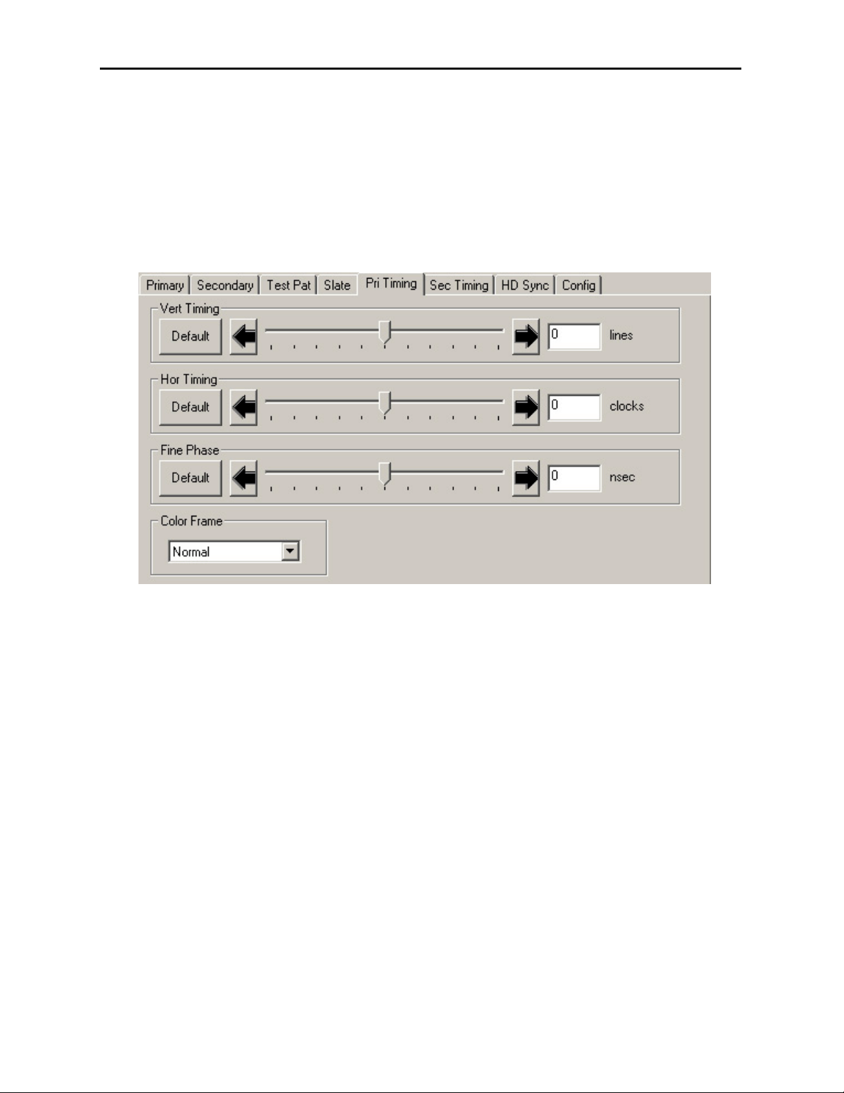
The Pri Timing menu shown below allows you to set the timing of the Primary composite
output in relation to the reference with the following controls. For numerical choices, use
the slider control to select a value or enter a value into the number field at right and press
the Enter key on your PC.
• Vert Timing – set the vertical timing in lines.
• Hor Timing – set the horizontal timing in clocks.
• Fine Phase – set the fine phase of the Primary output in nanoseconds.
• Color Frame – set the color framing for the Primary output signal.
Page 20
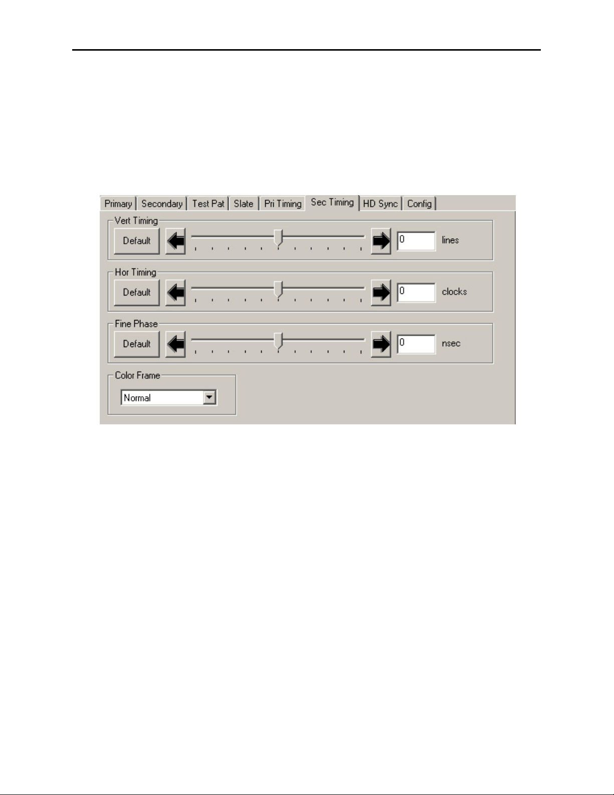
The Sec Timing menu shown below allows you to set the timing of the Secondary
composite output in relation to the reference or the Primary Source with the following
controls. For numerical choices, use the slider control to select a value or enter a value
into the number field at right and press the Enter key on your PC.
• Vert Timing – set the vertical timing in lines.
• Hor Timing – set the horizontal timing in clocks.
• Fine Phase – set the fine phase of the Secondary output.
• Color Frame – set the color framing for the Secondary output signal.
Model 5400 Dual Sync Gen/Test Signal Generator
5400-20
Page 21
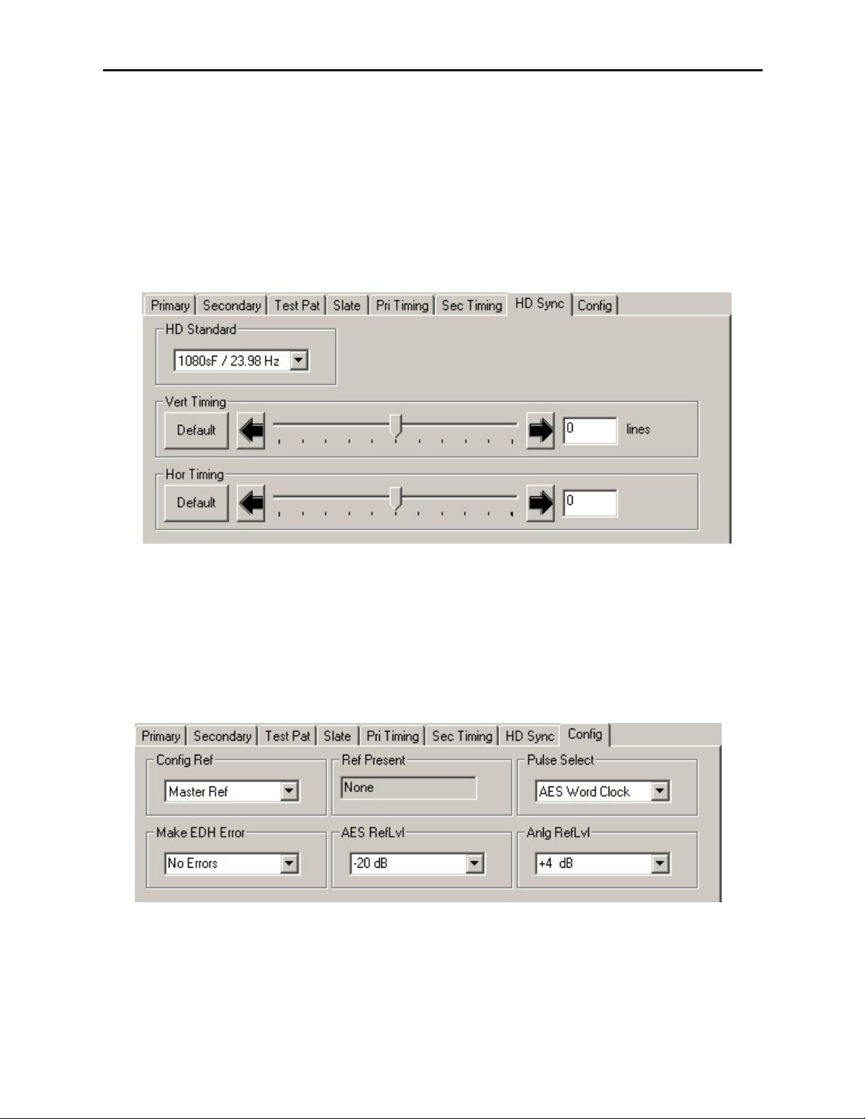
The HD Sync menu allows you to set the HD standard and timing of the HD Sync output
in relation to the Primary serial output with the following controls. For numerical choices,
use the slider control to select a value or enter a value into the number field at right and
press the Enter key on your PC.
• HD Standard – select the desired high definition standard for the sync output.
• Ver Timing – set the vertical timing in relation to the Primary serial output in
clocks.
• Hor Timing – set the horizontal timing of the HD sync output in relation to the
Primary serial output.
Model 5400 Dual Sync Gen/Test Signal Generator
Page 22
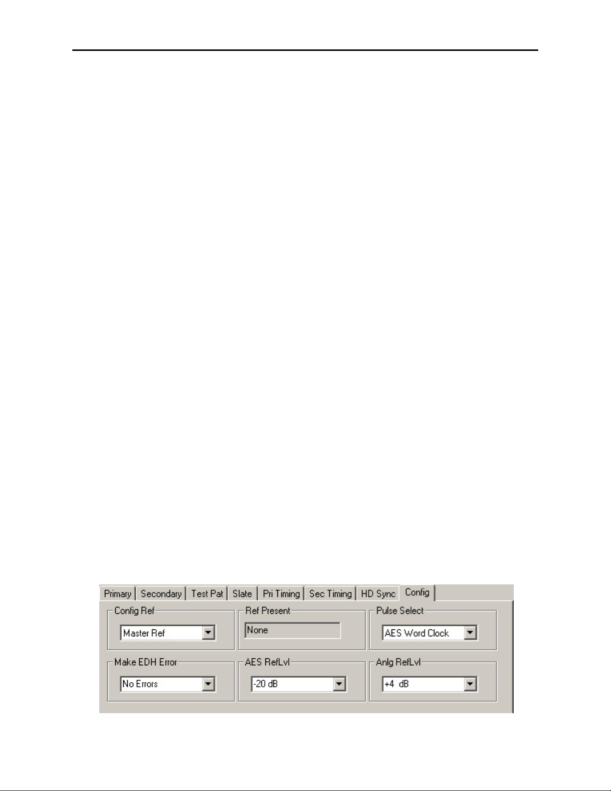
The Config menu allows you to configure the reference from the external input (525, 625
or 10 MHz sine wave) or the Master Frame Reference:
• Config Ref – select the desired module reference from the external input (525,
625 or 10 MHz sine wave) or Master Ref (Frame Reference).
The presence of the reference will be reported in the adjacent window.
• Pulse Select – set the type of pulse output desired for the AES Out 2/Wordclock
BNC on the rear of the frame. (Note that to enable a Wordclock or 6 Hz Pulse
output, jumper J3 must be set to WDCLK on the 5410 submodule. Refer to the
Installation section of this data pack for an illustration of this jumper.)
• Make EDH Error – this function allows introduction of specific EDH errors into
the SDI output stream for.testing downstream equipment. when the 5410 option is
present It can also be used to verify that corrective action or alarms are generated
at those downstream points as needed or expected. This mode resets to No Errors
upon reset or power is cycled (setting is not stored in non-volatile memory.) Error
types are summarized as follows:
• AP CRC Error – causes incorrect CRC for active picture to be transmitted
in EDH packet. Simulating a bit error, this should be detected as an EDH
error by downstream equipment.
• FF CRC Error – same as AP CRC Error above except it is the Full Frame
which is transmitted incorrectly.
• AP EDH Error – causes the AP EDH flag in the EDH packet to be set.
This simulates an error which was previously detected by upstream
equipment. The actual CRC will be correctly computed. This should be
detected downstream as an EDA error (Error Detected Already).
• FF EDH Error – same as AP EDH Error above except the Full Frame flag
is also set.
• AP EDA Error – causes the AP EDH flag to be set. This simulates a
stream where an error was detected by previous equipment. This error
should continue to be reported as EDA at every subsequent downstream
location.
• FF EDA Error – same as AP EDA Error above except also sets the Full
Frame flag.
• AES RefLvl – set the AES reference level to either -20 dB or -18 dB depending on
the audio requirement.
• Anlg RefLvl – set the analog reference level from –10 dBu to +8 dBu for the
Analog Tone Output.
Model 5400 Dual Sync Gen/Test Signal Generator
5400-22
Page 23
Model 5400 Dual Sync Gen/Test Signal Generator
Avenue Touch Screen Remote Configuration
The Avenue Touch Screen remote control status menu for this module is illustrated and
explained below. Refer to the 5400 Parameter Table for a summary of available parameters that can be set remotely through the menus illustrated. For more information on
using Avenue Touch Screen, refer to the Avenue Touch Screen data pack that came with
the option.
Parameter fields that are grayed out can indicate one of the following conditions:
• An option is not installed.
• The function is not active.
• The module is locked.
• The User Level set with Avenue PC is not accessible from the current User Level.
5400 Avenue Touch Screen Menus
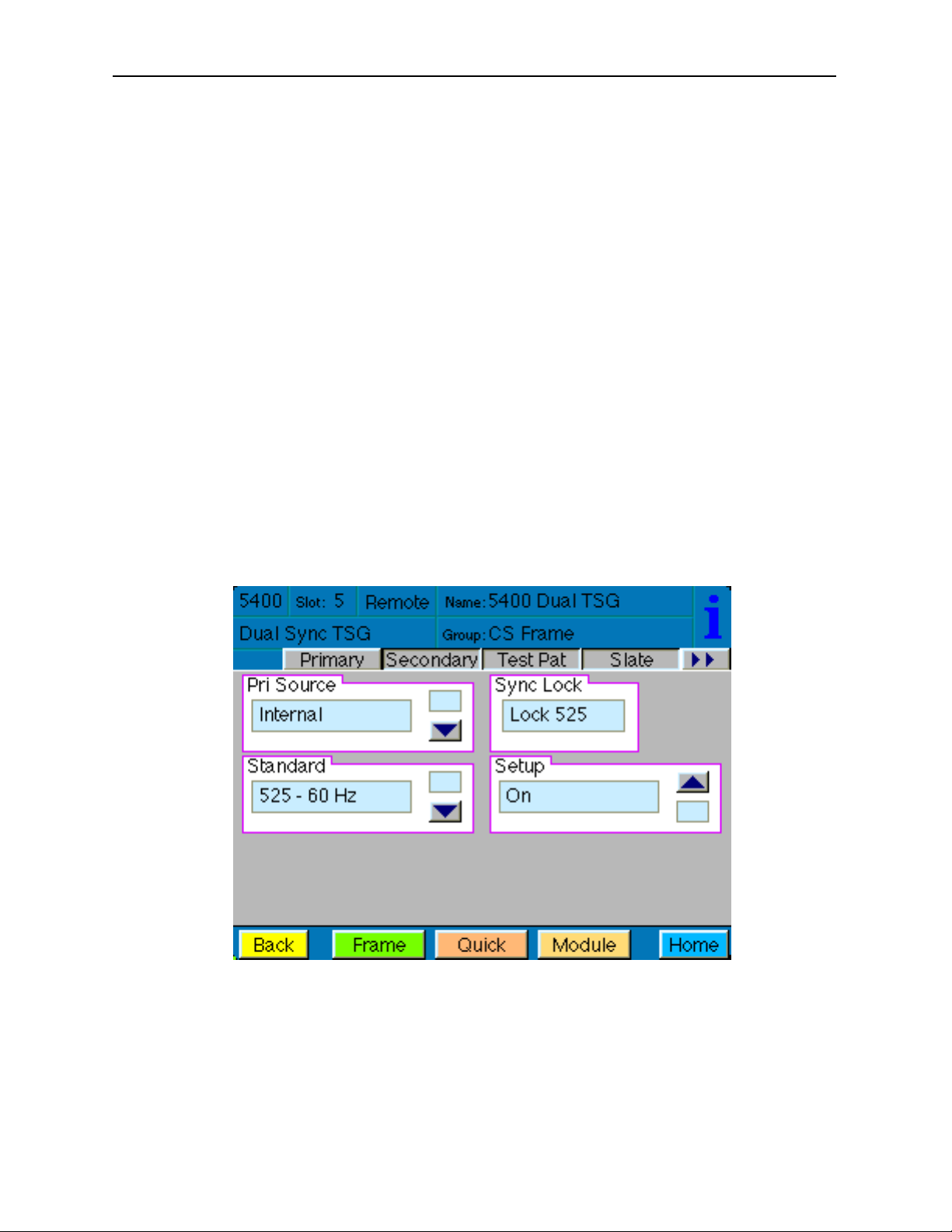
The Primary menu screen shown below allows you to set the following parameters for the
Primary generator output:
• Pri Source – select the Primary generator reference source from either Config
Ref (defined in the Config menu) or Internal.
• Standard – indicates what line standard the generator is locking to.
• Setup – sets setup to On or Off for 525–60 Hz line output signals.
The Sync Lock window shows what standard the module is locked to or No Lock.
5400-23
Page 24
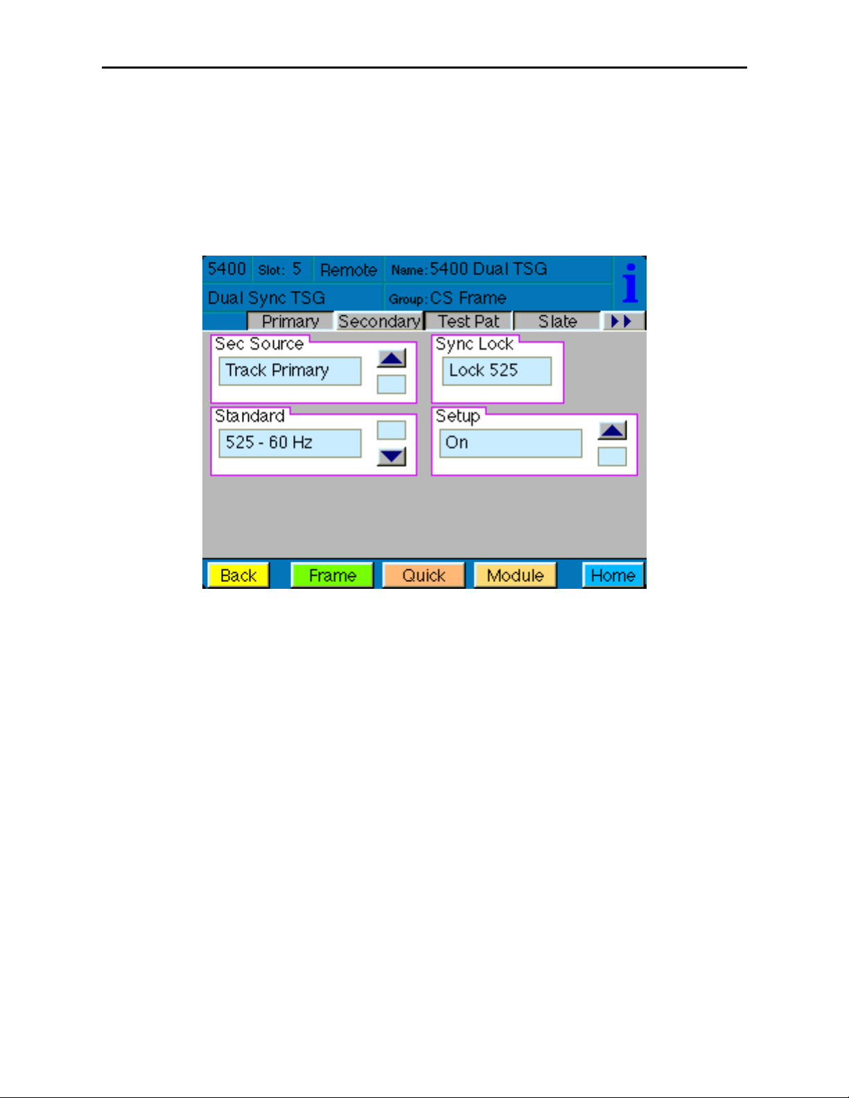
The Secondary menu screen shown below allows you to set the following parameters for
the Secondary generator output:
• Sec Source – select the Secondary generator reference source from either Config
Ref (defined in the Config menu), Internal or the choice to Track Primary.
• Standard – indicates what line standard the generator is locking to.
• Setup – sets setup to On or Off for 525–60 Hz line output signals.
The Sync Lock window shows what standard the module is locked to or No Lock.
Model 5400 Dual Sync Gen/Test Signal Generator
5400-24
Page 25
5400-25
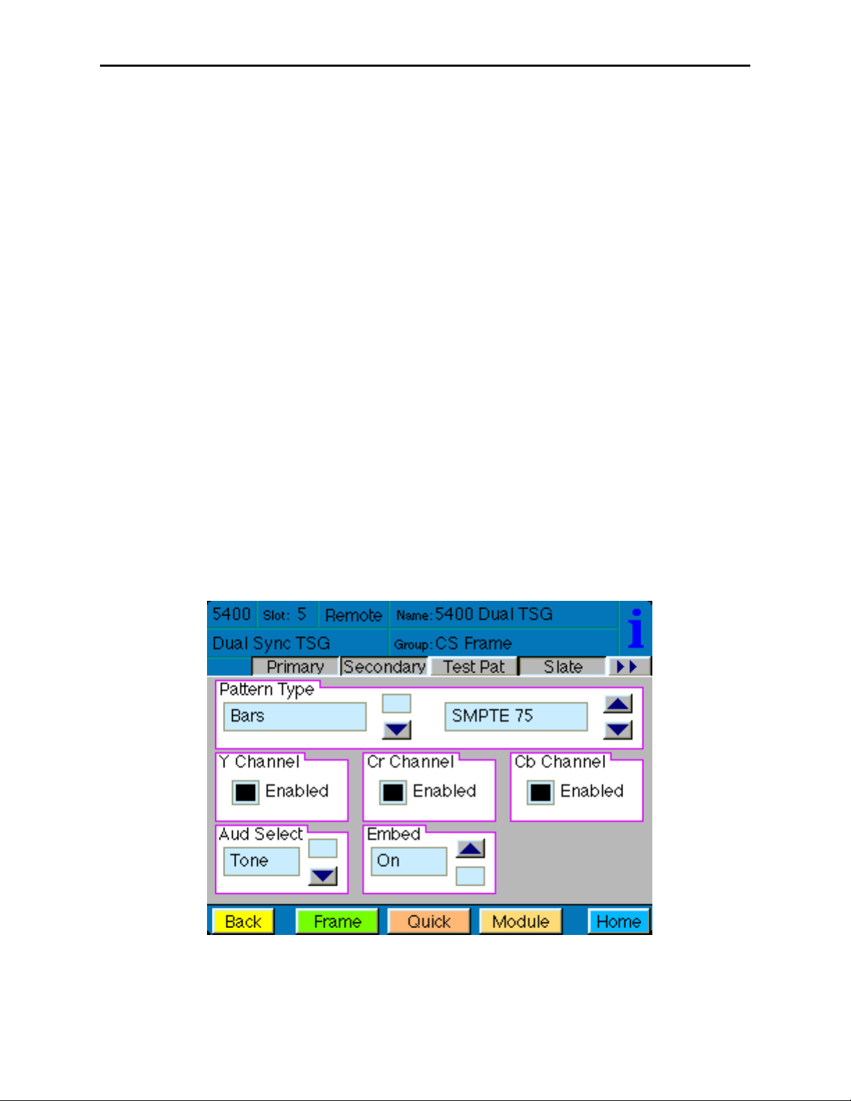
The Test Pattern menu screen shown below allows you to set the type of test pattern
desired for the Primary output. Refer to Appendix A for a complete description of each test
pattern.
Use the controls to set the following:
• Pattern Type – select the test signal type in the first window and the test signal
parameters in the second window. Refer to the 5400 Parameter Table shown
earlier for a complete listing of the available test signals and their parameters.
You may choose to turn off the Y, Cr and/or Cb Channels of some video signals if desired
for test purposes (such as the need for a monochrome signal for example). To turn off one
or more channels, deselect the Enabled check box.
When the 5410 optional audio submodule is installed, you may embed an audio tone, pop,
beep or silent in the Primary serial output and set the analog reference level with the
following controls:
• Aud Select – selects the format of the audio test signal to be output on the AES
and analog audio outputs. Choices for the audio test signal include the following:
Silent – digital audio equivalent of a color black signal.
Tone – continuous 1 KHz tone.
Pop – continuous tone with one and two beat interrupts representing
Channel 1 and Channel 2 respectively.
Beep – silent with one and two beat beeps representing Channel 1 and Channel 2
respectively.
• Embed – select whether or not to embed the audio test signal selected above in
the Primary serial output.
Model 5400 Dual Sync Gen/Test Signal Generator
Page 26

The Slate menu screen shown below allows you to define four different text overlays Use
the controls to set the following:
• Slate Select – select Off or the number of the slate to be defined from Slate 1-–4
or select GPI High or GPI Low to indicate to the external GPI device what state
will trigger a GPI input. Four GPI inputs are available corresponding to the four
slates.
• Top Line – clicking in this window will bring up an alphanumeric pad which
allows you to define the top line of the slate text.
• Bot Line – clicking in this window will bring up an alphanumeric pad which
allows you to define the bottom line of the slate text.
• Cyclops – adds a motion element to the video test signal which proves that the
signal reaching this destination is a true live signal and not a freeze frame from a
frame synchronizer that has lost its input. If an audio pop or beep has been
selected in the previous menu, it will synchronize with audio outputs (left is
channel 1, right is channel 2).
Model 5400 Dual Sync Gen/Test Signal Generator
5400-26
Page 27

The Pri Timing menu screen allows you to set the timing of the Primary composite
output in relation to the reference with the following controls. For numerical choices, use
the slider control to select a value or touch the number field at right to bring up a pop-up
keypad. Enter a value and press the Enter key.
• Vert Timing – set the vertical timing in lines.
• Hor Timing – set the horizontal timing in clocks.
• Fine Phase – set the fine phase of the Primary output in nanoseconds.
• Color Frame – set the color framing for the Primary output signal.
The Sec Timing menu allows you to set the timing of the Secondary output in relation to
the reference or the Primary Source with the following controls. For numerical choices,
use the slider control to select a value or touch the number field at right to bring up a
pop-up keypad. Enter a value and press the Enter key.
• Vert Timing – set the vertical timing in lines.
• Hor Timing – set the horizontal timing in clocks.
• Fine Phase – set the fine phase of the Secondary output.
• Color Frame – set the color framing for the Secondary output signal.
Model 5400 Dual Sync Gen/Test Signal Generator
5400-27
Page 28

The HD Sync menu screen shown below allows you to set the HD standard and timing of
the HD Sync output in relation to the Primary serial output with the following controls.
For numerical choices, use the slider control to select a value or touch the number field at
right to bring up a pop-up keypad. Enter a value and press the Enter key.
• HD Standard – select the desired high definition standard for the sync output.
• Ver Timing – set the vertical timing in relation to the Primary serial output in
clocks.
• Hor Timing – set the horizontal timing of the HD sync output in relation to the
Primary serial output.
The Config menu allows you to configure the reference from the external input (525, 625
or 10 MHz sine wave) or the Master Frame Reference:
• Config Ref – select the desired module reference from the external input (525, 625
or 10 MHz sine wave) or Master Ref (Frame Reference).
The presence of the reference will be reported in the adjacent window.
• Pulse Select – set the type of pulse output desired for the AES Out 2/Wordclock
BNC on the rear of the frame. (Note that to enable a Wordclock or 6 Hz Pulse
output, jumper J3 must be set to WDCLK on the 5410 submodule. Refer to the
Installation section of this data pack for an illustration of this jumper.)
• Make EDH Error – this function allows introduction of specific EDH errors into
the SDI output stream for.testing downstream equipment. when the 5410 option is
present It can also be used to verify that corrective action or alarms are generated
at those downstream points as needed or expected. This mode resets to No Errors
upon reset or power is cycled (setting is not stored in non-volatile memory.) Error
types are summarized as follows:
• AP CRC Error – causes incorrect CRC for active picture to be transmitted
in EDH packet. Simulating a bit error, this should be detected as an EDH
error by downstream equipment.
5400-28
Model 5400 Dual Sync Gen/Test Signal Generator
Page 29

• FF CRC Error – same as AP CRC Error above except it is the Full Frame
which is transmitted incorrectly.
• AP EDH Error – causes the AP EDH flag in the EDH packet to be set.
This simulates an error which was previously detected by upstream
equipment. The actual CRC will be correctly computed. This should be
detected downstream as an EDA error (Error Detected Already).
• FF EDH Error – same as AP EDH Error above except the Full Frame flag
is also set.
• AP EDA Error – causes the AP EDH flag to be set. This simulates a
stream where an error was detected by previous equipment. This error
should continue to be reported as EDA at every subsequent downstream
location.
• FF EDA Error – same as AP EDA Error above except also sets the Full
Frame flag.
• AES RefLvl – set the AES reference level to either -20 dB or -18 dB depending on
the audio requirement.
• Anlg RefLvl – set the analog reference level from –10 dBu to +8 dBu for the
Analog Tone Output.
5400-29
Model 5400 Dual Sync Gen/Test Signal Generator
Page 30

TROUBLESHOOTING
As a troubleshooting aid, the reference signal status and presence, power and CPU status
can be easily monitored from the front panel of this module using the front panel indicators.
Refer to the overall troubleshooting tips given below for the 5400 module:
Error light is lit on front panel:
• Module is not locking to a selected reference. At least one of the Ref LEDs
should be lit to indicate presence and status of reference input
No Pri or Sec LED indication:
• Module is not locking to 525 or 625. At least one of the Pri or Sec LEDs
LEDs should be lit to indicate locking status.
Can’t control module:
• Check status of CPU Run green LED. Should be blinking slowly and in
unison with other modules if System module is present. If not, try removing
it and plugging it in again to be sure it is seated properly.
• System module may not be working properly if installed.
Module controls are grayed out:
• Module is locked or access to module controls is restricted by User Level.
• Local/Remote switch on module is in the Local position.
No signal out of module:
• Check status of Ref green LEDs. One should be lit. If not, check the
reference input or master frame signal for presence and quality.
• Check cabling to input of module.
You may also refer to the technical support section of the Ensemble Designs web site for
the latest information on your equipment at the URL below:
http://www
.ensembledesigns.com/support
SOFTWARE UPDATING
Software upgrades for each module can be downloaded remotely if the optional System
Control module is installed. These can be downloaded onto your PC and then Avenue PC
will distribute the update to the individual module. (Refer to the Avenue PC documentation for more information) Periodically updates will be posted on our web site. If you do
not have the required System Control Module and Avenue PC, modules can be sent back
to the factory for software upgrades.
Model 5400 Dual Sync Gen/Test Signal Generator
5400-30
Page 31

Model 5400 Dual Sync Gen/Test Signal Generator
5400-31
WARRANTYAND FACTORY SERVICE
Warranty
This module is covered by a five year limited warranty, as stated in the main Preface of
this manual. If you require service (under warranty or not), please contact Ensemble
Designs and ask for customer service before you return the unit. This will allow the
service technician to provide any other suggestions for identifying the problem and
recommend possible solutions.
Factory Service
If you return equipment for repair, please get a Return Material Authorization Number
(RMA) from the factory first.
Ship the product and a written description of the problem to:
Ensemble Designs, Inc.
Attention: Customer Service RMA #####
870 Gold Flat Rd.
Nevada City, CA. 95959 USA
(530) 478-1830
Fax: (530) 478-1832
service@endes.com
http://www.ensembledesigns.com
Be sure to put your RMA number on the outside of the box.
Page 32

SPECIFICATIONS
5400 Dual Sync Generator/TSG
Reference Input Signal:
Number: Two: External or Frame Master Reference
Signal Type: 1 V p-p NTSC, PAL or 10 MHz
Impedance: 75 ohm
Return Loss: >40 dB
Composite Outputs:
Number: Two Primary, Two Secondary
Signal Type: NTSC/PAL
Impedance: 75 ohm
Return Loss: >40 dB
Frequency Response: ±0.1 dB 10 KHz to 5.0 MHz
Output DC: < 50 mV
K Factors: < 1.0% signal type
Differential Phase: < 1.0 degree
SCH Phase: ± 2 degrees
Delay: Adjustable over a full frame in subdegree steps
Color Framing: Tracks reference, user-selectable
Timing Stability:
Internal TCXO: ± 1 Hz of F
sc
External Ref: Follows reference
Timebase Error: < 1 ns
Serial Outputs:
Number: One Primary, One Secondary
Signal Type: Serial Digital, SMPTE 259M
Impedance: 75 ohm
Return Loss: > 15 dB
Tri-level Sync Output:
Number: One, 75 Ω
Type: 1080i (SMPTE 274M_4, 5, 6)
50, 59.94 or 60 Hz
720p (SMPTE 296M_1, 2, 3)
50, 59.94 or 60 Hz
1080p (SMPTE 274_9, 10, 11)
23.98, 24 or 25 Hz
1080sF (SMPTE RP211_14, 15, 16)
23.98, 24 or 25 Hz
DC: ± 50 mV
Return Loss: > 30 dB to 30 MHz
Model 5400 Dual Sync Gen/Test Signal Generator
5400-32
Page 33

AES Audio Output (Optional with 5410)
Number: Two
Type: AES3id 1kHz tone or silent
Resolution: 24 bit
Analog Audio Output (Optional with 5410)
Number: One stereo pair or two mono
Type: 1 kHz tone or silent
Impedance: 30 Ω, balanced
Reference Level: - 10 to +8 dBu, Adjustable
General Specifications:
Power Consumption: 10 Watts
Temperature Range: 0 to 40 degrees C ambient (all specs met)
Relative Humidity: 0 to 95% noncondensing
Altitude: 0 to 10,000 ft
Fusing: 1.5 Amp PTC resettable fuse
Due to ongoing product development, all specifications subject to change.
Model 5400 Dual Sync Gen/Test Signal Generator
5400-33
Page 34

Model 5400 Dual Sync Gen/Test Signal Generator
5400-34
Page 35

APPENDIX A
This appendix is provided to give details on each of the test patterns available on the
5400 module. The primary generator provides test patterns which can be used for evaluation of analog and digital video systems. Section A.1 lists the test patterns provided, and
Section A.2 provides a description of test patterns.
A.1 Test Patterns
All of the test patterns listed are available when using an Avenue remote control options
such as Avenue PC or a Touch Screen Panel. The nine patterns that are available in Local
mode are identified with the corresponding rotary switch position for selecting them.
Color Bars
Full Field 75%
Full Field 100%
Split Field w/Pluge 75%
Split Field w/Pluge 100% (Rotary Switch Setting 2)
SMPTE 75% (Rotary Switch Setting 1)
SMPTE 100%
Black
Black (Rotary Switch Setting 0)
50% Gray
80% Gray
White
Ramp
Video Ramp (Rotary Switch Setting 4)
Data Ramp
Shallow Ramp
5 Step
DAC Test
Sweep
Full Field
Sweep w/ Markers (Rotary Switch Setting 5)
Multiburst
Pulse & Bar
Window (Rotary Switch Setting 3)
Full Field
Component
Window 100
Window 20
Timing
Analog Blanking Markers
Digital Blanking Markers
Cosite (Rotary Switch Setting 6)
Interlace
Bowtie
5400-A1
Model 5400 Dual Sync Gen/Test Signal Generator
Page 36

Miscellaneous
Black
CrossHatch
SafeTitle (Rotary Switch Setting 8)
Unit Circle
Multi pattern (Rotary Switch Setting 9)
Multi composite
Pathological (Rotary Switch Setting 7)
16 by 9
A.2 TEST PATTERN DESCRIPTIONS
Color Bars
All of the color bar patterns include peak white, black, and the six vector colors (yellow,
cyan, green, magenta, red, and blue), either at 75% or 100%.
Full Field Bars
Full field bars is sometimes called simple bars as it does not include anything else.
It is color bars from the top of the field to the bottom.
100% is usually used for component signals as the amplitude of the Cb and Cr
signals is the same as the Y signal. A waveform monitor can be used to align Y, Cb,
and Cr gain.
75% is more commonly used with composite--when viewed on a waveform monitor,
the chroma yellow and cyan envelope is lined up with the peak white level. As
such, a waveform monitor can be used to align luminance and chrominance gain,
and a vector display can be used to align chroma phase.
Split Field w/Pluge
Pluge, or level reference is added to the color bars to make a split field. The pluge
is used to adjust monitor brightness and to check for clipping in digital systems.
The pluge includes +/- 2 IRE levels around black, four luminance steps, and a 5
IRE "top hat" above peak white.
In composite systems, monitor brightness can be adjusted using the +/- 2 IRE
levels around black by making the right-most level disappear in the adjacent black
while making the left-most level just visible.
In digital systems, the number of steps of dynamic range is limited by the number
of bits used to represent them. Black is represented by 040h and white is represented by 3ACh. If clipping occurs in the digital processing of a signal, the "top
hat" and/or the 2 IRE superblack level can be clip off.
5400-A2
Model 5400 Dual Sync Gen/Test Signal Generator
Page 37

SMPTE Color Bars
In addition to pluge, SMPTE Color Bars includes a reverse sequence of bars.
The reverse sequence helps adjust monitor levels on monitors that provide blue
only displays. Hue can be aligned by balancing the chroma bars, and chroma can
be set by matching the chroma bars to the white bars.
Black Test Patterns
These test patterns are field field luminance reference levels. Black can be used as a color
black reference signal and the others can be used as flat luminance mattes.
Black
The composite black test pattern has characteristics that are described in the
following table:
Characteristic Requirement
Black Level 7.5 +/- 1 IRE (NTSC)
0 +/- 1 IRE (PAL and Japan*)
Blanking Width 10.9 +/- 0.2 uSec
Sync Level -40 +/- 2 IRE (NTSC)
-300 +/- 15 mV (PAL)
Sync Width 4.7 +/- 0.1 uSec
Burst Level 40 +/- 1 IRE (NTSC)
300 +/- 15 mV (PAL)
Burst Frequency 3.579545 MHz (NTSC)
4.43361875 MHz (PAL)
SCH Phase 0 +/- 3 degrees
Color Field Sequence 4 Fields (NTSC)
8 Fields (PAL)
* Setup is removed with an on board jumper
The serial black pattern has a narrower blanking width of 10.2 uSec.
50%, 80%, and Peak White
These full field luminance mattes have 10 bit luminance levels of 1F6h, 2FDh, and
3ACh.
5400-A3
Model 5400 Dual Sync Gen/Test Signal Generator
Page 38

Ramp Test Patterns
Ramp test patterns are very useful for evaluating linearity, missing bits, timing errors,
and dynamic range.
If there is a problem with linearity, the ramp will not be a straight line. If there is a
missing bit, the ramp will be broken up into smaller ramps. If there is a timing error,
vertical lines which are often noisy can appear. If there is a dynamic range problem,
clipping will occur at the top or the bottom of the ramp.
Video Ramp
The video ramp test pattern goes from black to peak white across the line (040h to
3ACh for luminance and 040h to 3C0h for chrominance). Because there are more
samples in an active digital line than levels of gray and chroma, there are some
repeated steps across the line. This pattern is used especially for linearity, missing
bit levels, and timing errors.
Data Ramp
The data ramp test pattern goes from minimum to maximum legal digital values
(004h to 3FBh) in one step per sample increments. The ramp therefore restarts
part of the way across the line. Because it uses the entire dynamic range, it is
especially useful to check for clipping in each of the component channels, Y, Cb,
and Cr.
Shallow Ramp
The shallow ramp test pattern goes from 1E2h to 21Dh passing through the
critical 1FFh/200h point where all 10 bits change state. This pattern can be
examined closely using a waveform monitor to evaluate DAC/ADC step size uniformity and can be used to detect timing errors.
5 Step Ramp
The five step ramp test pattern has five steps:
Step 0: 040h and 040
Step 1: 0F0h and 0F4h
Step 2: 1A0h and 1A8h
Step 3: 252h and 25Ch
Step 4: 300h and 310h
Step 5: 3B0h and 3C4h
This pattern is used for aligning display systems such as a projector.
DAC Test
The DAC Test Pattern is alternating vertical bands of 1FFh and 200h across the
line.
At the transitions between 1FFh and 200h, all 10 bits of a digital signal change,
which can be problematic in DACs. Normally this step should not be visible on a
monitor, but if there is a problem, then vertical stripes will appear.
5400-A4
Model 5400 Dual Sync Gen/Test Signal Generator
Page 39

Sweep Test Patterns
Sweep test patterns are used to evaluate frequency response by examining the envelope of
the waveform on a waveform monitor.
Full Field Sweep
Luminance sweeps to 5.75 MHz and chrominance sweeps to 2.75 MHz.
Sweep with Markers
The addition of markers at 0.5, 1, 2, 3, 4, and 5 MHz in the luminance channel and
0.25, 0.5, 1, 1.5, 2, and 2.5 MHz in the chrominance channel assist in evaluating
response.
Multiburst
Instead of continuous sweep, discrete frequencies are positioned across the line.
Luminance frequencies are 0.5, 1, 2, 3, 4, and 5.75 MHz, and chrominance frequencies are 0.5, 1, 1.5, 2, 2.5, and 2.75.
Pulse and Bar Test Patterns
These test patterns are used to evaluate transient response and clamp performance.
Chroma-to-luminance delay, short-term distortion, gain, response, and tilt can be
measured.
Window
The window test pattern is comprised of a 2T pulse, a modulated 12.5T pulse and a
window bar.
The 2T pulse is used to measure short term distortion such as K2T, and transient
response such as KPB.
The modulated 12.5T pulse is used to evaluate chroma-to-luminance delay. When
viewed on a monitor, the bottom of the chroma envelope ideally appears as a flat
line. Group delay can distort the bottom of the envelope and, with the appropriate
waveform monitor graticule, can be measured.
The bar can be used to measure gain, and is also used to measure short-term distortion such as K
SD
and tilt such as K
BAR
.
Full Field Window
The window bar in this test pattern extends vertically for the full field.
Component Window
The component window test pattern has window bars added to the pattern. The
leading and trailing edges of the bars use T steps for both luminance and chrominance edges. Since the sampling frequency for chrominance is half that of
luminance however, the chrominance rise time is half that of the luminance. The
window bar also has an inverted 2T pulse in its midpoint.
The amplitudes of the three components are: Y-3ACh, Cb-3C0h, and Cr-040h.
Window 100/20
These window test patterns can be used for color balancing video monitors.
Window 20 provides a centered window with a luminance level of exactly 20% of
full white. Your monitor manufacturer will have provided instructions on the use of
test patterns such as these.
5400-A5
Model 5400 Dual Sync Gen/Test Signal Generator
Page 40

Timing Test Patterns
Timing test patterns are used to evaluate blanking area, field location, relative luma and
chroma timing, and cositing.
Analog Blanking Markers
The analog blanking markers test pattern draws a box around each field to show
the limits of blanking in composite systems. The size of the box is different for
NTSC than for PAL. In NTSC, the top of the field is at 21/284 and the bottom is at
262/525. In PAL, the top of the field is at 24/337 and the bottom is at 310/622.
The left and right markers are separated from digital blanking, which is narrower,
by a step so that actually blanking edges can be observed after passing through a
process that imposes blanking.
Digital Blanking Markers
The digital blanking markers test pattern draws a box around each field to show
the limits of blanking in digital systems. The size of the box is different for NTSC
than for PAL. In NTSC, the top of the field is at 20/283 and the bottom is at
262/525. In PAL, the top of the field is at 23/336 and the bottom is at 310/623.
The left and right markers are immediately inside EAV and SAV.
Cosite
The cosite test pattern assists in determining that the luminance and chrominance
parts of a digital signal are occurring in the appropriate relative time.
The vertical magenta pinstripe consists of a single cosite pulse in Y, Cb and Cr.
Because they are cosited and are only one sample wide, a mistiming of these components will not appear magenta on a monitor. Cb and Cr can be determined easily
on a waveform monitor because Cb is smaller than Cr. The levels are as follows:
Y-1B7h, Cb-3C0h, Cr-340h. The pinstripe is also useful because it is in the middle
of the line.
Interlace
The interlace test pattern is helpful to show that field 1 and field 2 are occurring in
the correct relationship to each other. A horizontal field timing strip and field 1/2
markers are included.
The horizontal field timing strip can be used to show that field 1 and field 2 are
cosited in time. The middle segment of the strip, which happens during field 1,
should occur between the outer segments, which happen during field 2. If it does
not, then the relative timing is shifted or the fields are swapped or missing.
The field markers help to identify which field is which. Field 1 has a roman
numeral "I" in it, and field two a roman numeral "II". If a field is missing, as in a
frame store in field mode, one of these markers will be missing. When viewed on a
waveform monitor or oscilloscope, the fields can also be identified. The field 1
marker has chroma content while the field 2 marker does not.
Bowtie
The bowtie test pattern is used to accurately measure the chroma to luma delay in
component systems in conjunction with a waveform monitor that is designed to use
it.
Model 5400 Dual Sync Gen/Test Signal Generator
5400-A6
Page 41

Miscellaneous Test Patterns
The following test patterns have special purposes.
Crosshatch
The crosshatch test pattern consists of horizontal and vertical lines organized in a
grid. This test pattern is used to evaluate monitor linearity and distortion.
SafeTitle
The safetitle test pattern identifies safe area in a video monitor for titles. If the
title stays inside the safe area, then monitors will always show the complete title
uncropped. The safe title pattern also shows the center of the visible area.
Unit Circle
When viewed on a component vectorscope, the unit circle test pattern displays a
circle of constant radius. This test pattern is useful for evaluating systems that
manipulate chroma such as chroma keyers.
Multi pattern
The multi pattern test pattern contains horizontal strips of other test signals,
including bars, reverse bars, pluge, video ramp, shallow ramp, sweep, markers for
sweep, multiburst, window, interlace, unit circle, and pathological patterns.
Viewed on a monitor, problems in a video system can often be discovered because
of the wide variety of signals present.
This single pattern can be used in conjunction with a waveform monitor that is
equipped with a line selector to display each of these patterns by selecting the line
to be viewed.
Multi composite
This test pattern is the same as the multi pattern above except the composite
version has the chroma channels of the ramp at reduced amplitude so that they do
not create illegal waveforms in composite.
Pathological
The pathological test pattern consists of a flat field of magenta color that is
precisely chosen because it produces long sequences of ones and zeroes in serial
digital systems. Because some systems are not tolerant of long sequences, this
pattern can help to identify those systems.
When a pathological error occurs, this test pattern shows horizontal, intermittent
black lines.
16 by 9
This pattern is intended for use in standard definition systems that are producing
anamorphic material for 16:9 HD viewing. This pattern provides safetitle marking
for both SD and HD aspect ratios. It also includes a color bar pattern which is horizontally compressed such that when displayed on a 16:9 monitor, the color bar
portion will have a 4:3 aspect ratio.
Model 5400 Dual Sync Gen/Test Signal Generator
5400-A7
Page 42

Model 5400 Dual Sync Gen/Test Signal Generator
5400-A6
 Loading...