

Page 1

This data pack provides detailed installation, configuration and operation information for
both the 5360 and 5365 Four Channel Analog to Digital Video Converters and
Embedders module as part of the Avenue Signal Integration System.
The module information in this data pack is organized into the following sections:
• 5360 and 5365 Overview
• Applications
• Installation
• Cabling
• Module Configuration and Control
°
Front Panel Controls and Indicators
°
Avenue PC Remote Control
°
Avenue Touch Screen Remote Control
• Troubleshooting
• Software Updating
• Warranty and Factory Service
• Specifications
5360-1
Models 5360 and 5365
Four Channel
Analog to Digital Video
Converters and
Embedders Data Pack
Revision 1.3 SW v2.2.1
ENSEMBLE
DESIGNS
Page 2

5360 AND 5365 OVERVIEW
The Avenue 5360 and 5365 modules convert four channels of analog video and audio to
four streams of SD SDI with embedded audio. Use these modules with routers, switchers,
remote trucks or any application that requires many channels of high quality video and
conversion. This is a perfect solution for satellite installations that need to feed a large
number of analog signals from IRDs into a monitor wall. Refer to the block diagram on the
following page.
12 bit analog to digital conversion, digital decoding of the composite input, and adaptive
comb filtering ensure superior output signals. Proc amp functions allow adjustment of
video, chroma, setup and hue.
Analog audio inputs are digitized at 24 bits of resolution and then embedded into the associated video signal.
5360 (but not the 5365) also has a genlock reference input and a TBC/Frame Sync for each
of the four conversion channels. The 5360 can accept noisy asynchronous inputs and is
well suited for feeds from remote trucks and satellite receivers. Additionally, the 5360’s
outputs are independently timeable.
Like all Avenue modules, every function and parameter of the 5360 and 5365 can be controlled from an Avenue Touch Screen, Express Control Panel, or the Avenue PC Control
Application. The Express Control Panel works very nicely for live shading with its
dedicated video, chroma, pedestal, and hue knobs. The continuous rotation velocity
sensitive knobs are responsive and dependable.
5360 and 5365 module memory registers can be used to save the complete configuration of
the modules, making it easy to change instantly between different configurations.
Modules at software version 2.2.0 or later support SNMP (Simple Network Management
Protocol) monitoring. For each applicable signal processing module, module, signal, and
reference status are reported. For complete details on using SNMP monitoring, refer to
the Avenue System Overview section in the manual that accompanies each frame.
Models 5360 and 5365 Four Channel Analog to Digital Video Converters and Embedders
5360-2
Page 3
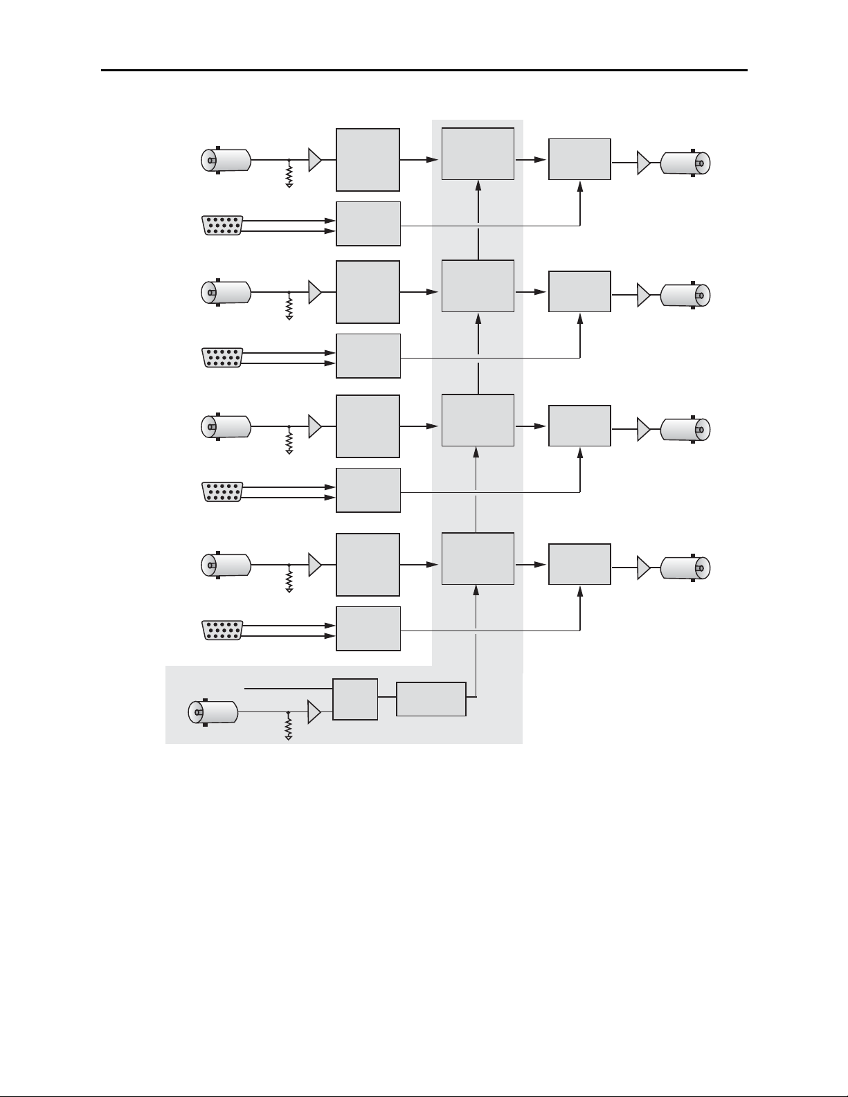
Models 5360 and 5365 Four Channel Analog to Digital Video Converters and Embedders
Functional Block Diagram.
Note: The shaded area indicates functionality unique to the 5360.
Models 5360 and 5365 Four Channel Analog to Digital Video Converters and Embedders
5360-3
Channel
One
Channel
Two
Channel
Three
Composite Input
Analog Audio Input
Composite Input
Analog Audio Input
Composite Input
Analog Audio Input
12 bit
A to D
Converter
& Decoder
24 Bit
ADC
12 bit
A to D
Converter
& Decoder
24 Bit
ADC
12 bit
A to D
Converter
& Decoder
24 Bit
ADC
TBC
Frame Sync
Proc Amp
TBC
Frame Sync
Proc Amp
TBC
Frame Sync
Proc Amp
Audio
SD SDI Output
Mux
SD SDI Output
Audio
Mux
SD SDI Output
Audio
Mux
TBC
Frame Sync
Proc Amp
Audio
SD SDI Output
Mux
Channel
Four
Composite Input
12 bit
A to D
Converter
& Decoder
Analog Audio Input
24 Bit
ADC
Master Ref
External Ref Input
Sync
Detector
Genlock
Timing Adjust
5360 Only
Page 4
Models 5360 and 5365 Four Channel Analog to Digital Video Converters and Embedders
APPLICATIONS
This section provides a typical application for using the 5360 Video ADC/TBC module.
Satellite Reception
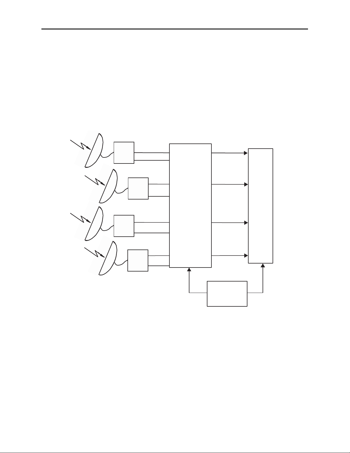
As illustrated in the block diagram below, the 5360 will accept up to four analog inputs,
convert them to serial digital, then lock the signals to the house reference with full timing
capability.
This type of application for converting noisy asynchronous satellite receiver inputs is ideal
for the 5360. Each channel can be adjusted independently for video processing and timed
to the house reference to feed a digital facility router.
5360-4
Channel 1
Channel 1
Satellite
Rcvr 1
Channel 3 Channel 3
Satellite
Rcvr 3
Channel 2
Channel 2
Satellite
Rcvr 2
Channel 4
Channel 4
Satellite
Rcvr 4
Analog Inputs
Digital Outputs
Digital
Router
5360 ADC with
TBC/Frame Sync
House
Reference
Composite
Analog Audio
Analog Audio
Composite
Composite
Composite
Analog
Audio
Analog
Audio
SD SDI with
embedded audio
SD SDI with
embedded audio
SD SDI with
embedded audio
SD SDI with
embedded audio
Satellite Application Block Diagram
Page 5

5360-5
Models 5360 and 5365 Four Channel Analog to Digital Video Converters and Embedders
INSTALLATION
5360 and 5365 ADC Modules
Plug the 5360 or 5365 modules into any one of the slots in the 1 RU or 3 RU frame and
install the plastic overlay provided onto the corresponding group of rear BNC connectors
associated with the module location. Note that the plastic overlay has an optional
adhesive backing for securing it to the frame. Use of the adhesive backing is only
necessary if you would like the location to be permanent and is not recommended if you
need to change module locations. These modules may be hot-swapped (inserted or
removed) without powering down or disturbing performance of the other modules in the
system.
CABLING
Refer to the 3 RU and 1 RU backplane diagrams of the module on the following page for
cabling instructions. Note that unless stated otherwise, the 1 RU cabling explanations are
identical to those given in the 3 RU diagram.
Page 6
5360-6
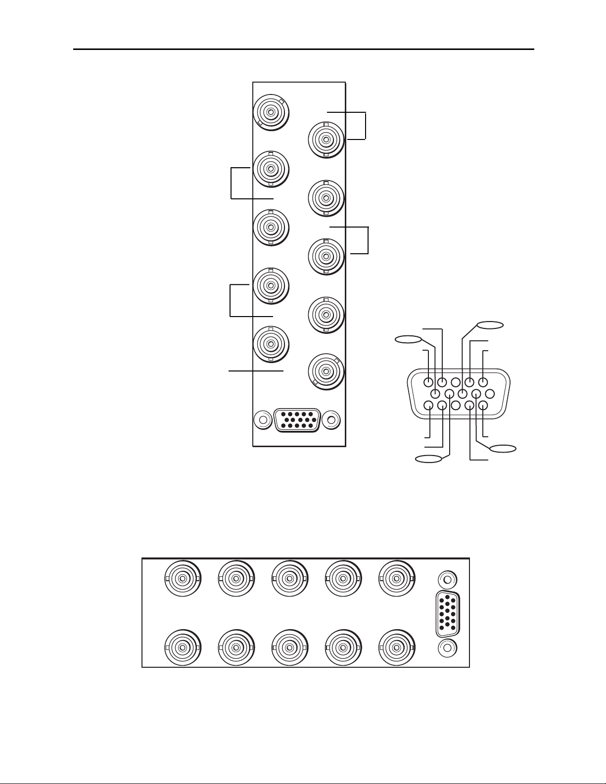
3 RU Backplane
SDI Out 1
SDI Out 2
SDI Out 3
5360 ADC
Ref In
Cpst In 1
Cpst In 2
Cpst In 4
SDI Out 4
Cpst In 3
Audio
1 RU Backplane
Connect a composite input to be
converted to Cpst In 1 and the
converted output SDI Out 1 to an
SDI destination.
Models 5360 and 5365 Four Channel Analog to Digital Video Converters and Embedders
Ref In – Connect a composite
video input (PAL or NTSC) to the
external reference input.
Connect a composite input to be
converted to Cpst In 2 and the
converted output SDI Out 2 to an
SDI destination.
Connect a composite input to be
converted to Cpst In 3 and the
converted output SDI Out 3 to an
SDI destination.
Connect a composite input to be
converted to Cpst In 4 and the
converted output SDI Out 4 to an
SDI destination.
Vid Ch 4
Aud Ch 2
Aud Ch 1
Vid Ch 3
Aud Ch 1
Aud Ch 2
1
6
11
SDI Out 1 SDI Out 4SDI Out 3
5360 ADC
SDI Out 2
Aud Ch 1
Aud Ch 2
Vid Ch 1
Cpst In 4Cpst In 3Cpst In 2Cpst In 1
Ref In
Audio
Aud Ch 2
Aud Ch 1
Vid Ch 2
Page 7
5360-7
Models 5360 and 5365 Four Channel Analog to Digital Video Converters and Embedders
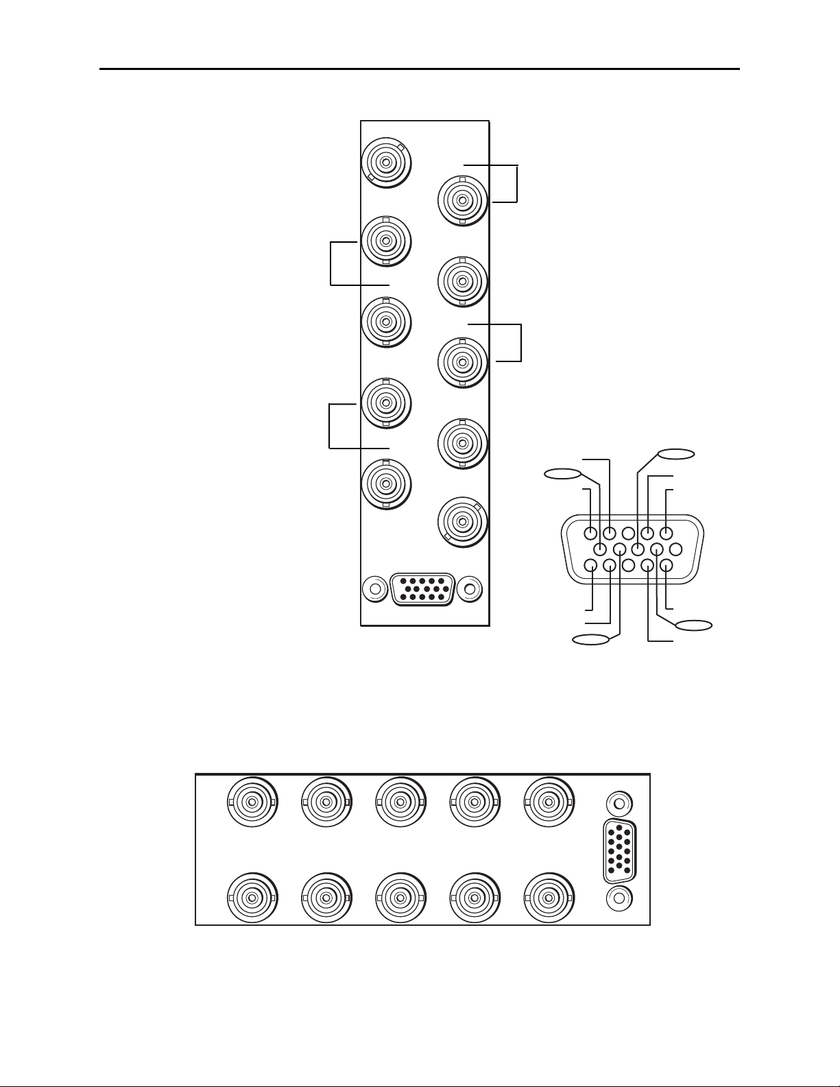
3 RU Backplane
SDI Out 1
SDI Out 2
SDI Out 3
5365 ADC
Cpst In 1
Cpst In 2
Cpst In 4
SDI Out 4
Cpst In 3
Audio
1 RU Backplane
Connect a composite input to be
converted to Cpst In 1 and the
converted output SDI Out 1 to an
SDI destination.
Connect a composite input to be
converted to Cpst In 2 and the
converted output SDI Out 2 to an
SDI destination.
Connect a composite input to be
converted to Cpst In 3 and the
converted output SDI Out 3 to an
SDI destination.
Connect a composite input to be
converted to Cpst In 4 and the
converted output SDI Out 4 to an
SDI destination.
Vid Ch 4
Aud Ch 2
Aud Ch 1
Vid Ch 3
Aud Ch 1
Aud Ch 2
SDI Out 1 SDI Out 4SDI Out 3SDI Out 2
5365 ADC
Cpst In 4Cpst In 3Cpst In 2Cpst In 1
Aud Ch 1
Aud Ch 2
Vid Ch 1
1
6
11
Aud Ch 2
Aud Ch 1
Vid Ch 2
Audio
Page 8

Models 5360 and 5365 Four Channel Analog to Digital Video Converters and Embedders
MODULE CONFIGURATION AND CONTROL
The configuration parameters for each Avenue module must be selected after installation.
This can be done remotely using one of the Avenue remote control options or locally using
the module front panel controls. Each module has a REMOTE/LOCAL switch on the
front edge of the circuit board which must first be set to the desired control mode.
The configuration parameter choices for the module will differ between Remote and
Local modes. In Remote mode, the choices are made through software and allow more
selections. The 5360 and 5365 Parameter Tables later in this section summarize and
compare the various configuration parameters that can be set remotely or locally and the
default/factory settings. They also provide the default User Levels for each control. These
levels can be changed using the Avenue PC application.
If you are not using a remote control option, the module parameters must be configured
from the front panel switches. Parameters that have no front panel control will be set to a
default value. The Local switches are illustrated in the Front Panel Controls and
Indicators section following the 5360 and 5365 Parameter Tables.
Avenue module parameters can be configured and controlled remotely from one or both of
the remote control options, the Avenue Touch Screen or the Avenue PC Application. Once
the module parameters have been set remotely, the information is stored on the module
CPU. This allows the module to be moved to a different cell in the frame at your discretion without losing the stored information. Remote configuration will override whatever
the switch settings are on the front edge of the module.
For setting the parameters remotely using the Avenue PC option, refer to the Avenue PC
Remote Configuration section of this document.
For setting the parameters remotely using the Avenue Touch Screen option, refer to the
Avenue Touch Screen Remote Configuration section of this document following
Avenue PC.
Express Panel operation is described in the data pack that accompanies the control panel
option.
5360-8
Page 9

Models 5360 and 5365 Four Channel Analog to Digital Video Converters and Embedders
5360-9
5360 Parameter Table
CONTROL LOCAL REMOTE
FACTORY
DEFAULT
DEFAULT
USER LEVEL
Ch 1-4 Blanking Wide
Narrow
(PAL Lines 1-6<
NTSC Lines 1-9)
Wide
(PAL Lines 1-22<
NTSC Lines 1-20)
Wide Admin
Ch 1-4 Reference
Source
Ext Ref
Ext Ref
Master Ref
Video In Ref
Ext Ref Admin
Ch 1-4 Setup Removal Off
Off
On
Off Admin
Ch 1-4 Signal Mute No Muting
No Muting
Mutes on Noise
Freezes on Noise
No Muting Level 1
Ch 1-4 Test Pattern Off
Off
On
Off Level 1
Ch 1-4 Comb Filter 3 Line
3 Line
5 Line
3 Line Level 1
Ch 1-4 Gain 100% 0 – 150% 100% Admin
Ch 1-4 Chroma 100% 0 – 150% 100% Admin
Ch 1-4 Pedestal 0 IRE +/– 30 IRE 0 IRE Admin
Ch 1-4 Hue 0 degrees +/– 180 degrees 0 degrees Admin
Ch 1-4 TBC/Frame Sync
Sw 1:TBC 1
Sw 2:TBC 2
Sw 3:TBC 3
Sw 4:TBC 4
Off
On
On Admin
Ch 1-4 HorizontalTiming 0 clocks
+/– 1700 clocks
0 clocks Admin
Ch 1-4 Vertical Timing 0 lines +/– 620 lines 0 lines Admin
Ch 1-4 Audio Gain 0 dB -700 to 120 dB 0 dB Admin
Ch 1-4 Embedding Group 1 Off, Group 1,
Group 2, Group 3,
Group 4
Group 1 Admin
Ch 1-4 Anlg Ref Level +4 dB -10 dB, -6 dB, -4 dB,
0 dB, +4 dB
+4 dB Admin
Reference Source Ext Ref
Ext Ref
Master Ref
Video In Ref
Ext Ref Admin
Dig Ref Level -20 dBFS -18 dBFS,
-20 dBFS
-20 dBFS Admin
Page 10

5360-10
Models 5360 and 5365 Four Channel Analog to Digital Video Converters and Embedders
5365 Parameter Table
CONTROL LOCAL REMOTE
FACTORY
DEFAULT
DEFAULT
USER LEVEL
Ch 1-4 Blanking Wide
Narrow
(PAL Lines 1-6<
NTSC Lines 1-9)
Wide
(PAL Lines 1-22<
NTSC Lines 1-20)
Wide Admin
Ch 1-4 Setup Removal Off
Off
On
Off Admin
Ch 1-4 Signal Mute No Muting
No Muting
Mutes on Noise
Freezes on Noise
No Muting Level 1
Ch 1-4 Test Pattern Off
Off
On
Off Level 1
Ch 1-4 Comb Filter 3 Line
3 Line
5 Line
3 Line Level 1
Ch 1-4 Gain 100% 0 – 150% 100% Admin
Ch 1-4 Chroma 100% 0 – 150% 100% Admin
Ch 1-4 Pedestal 0 IRE +/– 30 IRE 0 IRE Admin
Ch 1-4 Hue 0 degrees +/– 180 degrees 0 degrees Admin
Ch 1-4 HorizontalTiming 0 clocks
+/– 1700 clocks
0 clocks Admin
Ch 1-4 Vertical Timing 0 lines +/– 620 lines 0 lines Admin
Ch 1-4 Audio Gain 0 dB -700 to 120 dB 0 dB Admin
Ch 1-4 Audio
Embedding
Group 1 Off, Group 1,
Group 2, Group 3,
Group 4
Group 1 Admin
Ch 1-4 Anlg Ref Level +4 dB -10 dB, -6 dB, -4 dB,
0 dB, +4 dB
+4 dB Admin
Dig Ref Level -20 dBFS -18 dBFS,
-20 dBFS
-20 dBFS Admin
Page 11

Front Panel Controls and Indicators
Each front edge indicators and switch settings are shown in the diagrams below:
Remote/Local switch:
Set to the mode you
will be using.
Pwr green LED:
Indicates the presence (ON) or
absence (OFF) of power (+5V).
Run green LED:
OFF:
A power fault or halted CPU
ON:
A halted CPU
FAST BLINK:
CPU Run error
SLOW BLINK:
System OK. (If SPI control
is active from the main
frame System Control
Module, all Run indicators
will be synchronized.)
Ch 1-4 Input green LEDs:
On indicates input video signal
is present and detected on each
individual channel.
OFF no input video signal detected
on the input of each channel.
Ref green LED:
On when the external reference
source is detected.
OFF when no reference signal is
detected.
TBC 1-4
switches:
Turn Time Base Correction On (left)
or Off (right) for each individual
channel with the corresponding
TBC 1-4 switches.
Models 5360 and 5365 Four Channel Analog to Digital Video Converters and Embedders
5360-11
5360
4
Channel
ADC / TBC
Input 1
Input 2
Input 3
Run
Pwr
Input 4
Ref Pres
Remote
Local
TBC 1
TBC 2
TBC 3
TBC 4
on
Page 12

Remote/Local switch:
Set to the mode you
will be using.
Pwr green LED:
Indicates the presence (ON) or
absence (OFF) of power (+5V).
Run green LED:
OFF:
A power fault or halted CPU
ON:
A halted CPU
FAST BLINK:
CPU Run error
SLOW BLINK:
System OK. (If SPI control
is active from the main
frame System Control
Module, all Run indicators
will be synchronized.)
Ch 1-4 Input
green LEDs:
On indicates input video signal
is present and detected on each
individual channel.
OFF no input video signal detected
on the input of each channel.
Models 5360 and 5365 Four Channel Analog to Digital Video Converters and Embedders
5360-12
5365
4
Channel
ADC
Input 1
Input 2
Input 3
Input 4
Remote
Local
on
Run
Pwr
Page 13

Models 5360 and 5365 Four Channel Analog to Digital Video Converters and Embedders
Avenue PC Remote Configuration
The Avenue PC remote control menus for these module are illustrated and explained
below. Refer to the 5360 and 5365 Parameter Tables for a summary of available parameters that can be set remotely through the menus illustrated.
Parameter fields that are grayed out can indicate one of the following conditions:
• An option is not installed.
• The function is not active.
• The module is locked.
• The User Level set with Avenue PC is not accessible from the current User Level.
5360 and 5365 Avenue PC Menus
The Config 1 menu example shown below shows the configuration parameters available
for each individual channel 1 – 4 in their respective Config menus.
• Blanking – use this control to set the blanking for the channel as Narrow (lines
1-9 are blanked in NTSC, lines 1-6 in PAL) or Wide (lines 1-20 in NTSC, lines 1-22
in PAL).
• Setup Removal – use this control to turn setup removal On or Off depending on
the requirement of the input signal.
• Signal Mute – set the action of the output when the input signal is lost. Available
values are No Muting, Mutes on Noise, Freeze on Noise.
• Test Pattern – turn a Color Bars test pattern on or off. Available values are Off,
Bars, Black.
• Comb Mode – set the comb mode for 3 Line (best for video with motion) or
5 Line decoding.
Status reporting is provided for the following conditions:
• Input – reports the input status as No Input, 525 Lock, or 625 Lock.
Repeat the configuration for each of the four input channels with their respective Config
menus.
5360-13
Page 14

Models 5360 and 5365 Four Channel Analog to Digital Video Converters and Embedders
The Proc 2 menu shown below gives an example of the adjustable video processing
parameters for each channel in their respective Proc 1 – 4 menus:
• Gain – adjust the percentage of overall gain (luminance and chrominance).
Available value range: 0 – 150%.
• Chroma – adjust the percentage of chroma amplitude. Available value range:
0 – 150%.
• Pedestal – adjust the pedestal (black) level of the signal in IRE. Available value
range: -30 – 30 IRE.
• Hue – adjust the hue of the signal ± 180 degrees.
Use the TBC 1 – 4 menus as shown in the example on the next page for Channel 1 to turn
the time base corrector/frame sync function on and off, then adjust horizontal and vertical
timing independently for each of the four channels with their respective TBC menus:
• TBC/FrameSync – turn TBC and Frame Sync functionality On or Off. The TBC
Status window next to the control will indicate what the channel is locked to.
• Hor Time – adjust the horizontal timing of the channel in clocks. Available value
range: -1700 to 1700.
• Ver Time – adjust the vertical timing of the channel in lines. Available value
range: -620 to 620.
NOTE: The TBC menus are for model 5360 only. The 5365 does not have the TBC (time
base corrector) functionality.
5360-14
Page 15

The Audio 1 menu example shown below shows the configuration parameters available
for each individual channel 1 – 4 in their respective Audio menus.
• Audio Gain – use this control to adjust the audio gain as desired, ranging from
-700 to 120 dB.
• Embedding – use the drop-down menu to select the audio group to embed into
the SDI output. Select from Off, Group 1, Group 2, Group 3, and Group 4.
• Anlg Ref Level – use the drop-down menu to select the analog reference level for
embedding. Available values are: -10 dB, -6 dB, -4 dB, 0 dB, +4 dB.
5360-15
Models 5360 and 5365 Four Channel Analog to Digital Video Converters and Embedders
Page 16

Models 5360 and 5365 Four Channel Analog to Digital Video Converters and Embedders
NOTE: The Config All menu as shown below is for model 5360. For the 5365, the Config
All menu contains only the Dig Ref Level field.
The Config All menu shown below allows you to select and monitor the reference for all
channels as follows:
• Ref Source – select the external input reference. Available values are: Ext Ref,
Master Ref.
• The status of the reference input will be displayed in the Reference read-only
window.
• Dig Ref Level – set the digital reference output level for the audio output. Select
either -20 dBFS or -18 dBFS.
The Memory menu shown below allows you to save overall module setups to five memory
registers as follows:
• Select Save, then one of the five memory registers Reg 1 – 5. The box will turn
green. The entire module setup is now saved in the selected register.
• To recall a register, select the register box. If there is information saved, the box
will turn green. The saved setup will now be loaded to the module. Up to five
different module setups can be saved and recalled using the individual registers.
5360-16
Page 17

Avenue Touch Screen Remote Configuration
The Avenue Touch Screen remote control menus for this module are illustrated and
explained below. Refer to the 5360 and 5365 Parameter Tables for a summary of
available parameters that can be set remotely through the menus illustrated.
Parameter fields that are grayed out can indicate one of the following conditions:
• An option is not installed.
• The function is not active.
• The module is locked.
• The User Level set with Avenue PC is not accessible from the current User Level.
5360 Touch Screen Menus
The Config 1 menu example shown below shows the configuration parameters available
for each individual channel 1 – 4 in their respective Config menus.
• Blanking – use this control to set the blanking for the channel as Narrow (lines
1-9 are blanked in NTSC, lines 1-6 in PAL) or Wide (lines 1-20 in NTSC, lines 1-22
in PAL).
• Setup Removal – use this control to turn setup removal On or Off depending on
the requirement of the input signal.
• Signal Mute – set the action of the output when the input signal is lost. Available
values are No Muting, Mutes on Noise, Freeze on Noise.
• Test Pattern – turn a Color Bars test pattern on or off. Available values are Off,
Bars, Black.
• Comb Mode – set the comb mode for 3 Line (best for video with motion) or
5 Line decoding.
Status reporting is provided for the following conditions:
• Input – reports the input status as No Input, 525 Lock, or 625 Lock.
5360-17
Models 5360 and 5365 Four Channel Analog to Digital Video Converters and Embedders
Page 18

Models 5360 and 5365 Four Channel Analog to Digital Video Converters and Embedders
Repeat the configuration for each of the four input channels with their respective Config
menus.
The Proc 2 menu shown below gives an example of the adjustable video processing
parameters for each channel in their respective Proc 1 – 4 menus:
• Gain – adjust the percentage of overall gain (luminance and chrominance).
Available value range: 0 – 150%.
• Chroma – adjust the percentage of chroma amplitude. Available value range:
0 – 150%.
• Pedestal – adjust the pedestal (black) level of the signal in IRE. Available value
range: -30 – 30 IRE.
• Hue – adjust the hue of the signal ± 180 degrees.
Use the TBC 1 – 4 menus as shown in the example on the next page for Channel 1 to
turn the time base corrector/frame sync function on and off, then adjust horizontal and
vertical timing independently for each of the four channels with their respective TBC
menus:
• TBC/FrameSync – turn TBC and Frame Sync functionality On or Off. The TBC
Status window next to the control will indicate what the channel is locked to.
• Hor Time – adjust the horizontal timing of the channel in clocks.
• Ver Time – adjust the vertical timing of the channel in lines.
NOTE: The TBC menus are for model 5360 only. The 5365 does not have the TBC (time
base corrector) functionality.
5360-18
Page 19

5360-19
The Audio 1 menu example shown below shows the configuration parameters available
for each individual channel 1 – 4 in their respective Audio menus.
• Audio Gain – use this control to adjust the audio gain as desired, ranging from
-700 to 120 dB.
• Embedding – use the drop-down menu to select the audio group to embed into the
SDI output. Select from Off, Group 1, Group 2, Group 3, and Group 4.
• Anlg Ref Level – use the drop-down menu to select the analog reference level for
embedding. Available values are: -10 dB, -6 dB, -4 dB, 0 dB, +4 dB.
Models 5360 and 5365 Four Channel Analog to Digital Video Converters and Embedders
Page 20

NOTE: The Config All menu as shown below is for model 5360. For the 5365, the Config
All menu contains only the Dig Ref Level field.
The Config All menu shown below allows you to select and monitor the reference for all
channels as follows:
• Ref Source – select the external input reference. Available values are: Ext Ref,
Master Ref.
• The status of the reference input will be displayed in the Reference read-only
window.
• Dig Ref Level – set the digital reference output level for the audio output. Select
either -20 dBFS or -18 dBFS.
The Memory menu shown below allows you to save overall module setups to five memory
registers as follows:
• Select Save, then one of the five memory registers Reg 1 – 5. The box will turn
green. The entire module setup is now saved in the selected register.
• To recall a register, select the register box. If there is information saved, the box
will turn green. The saved setup will now be loaded to the module. Up to five
different module setups can be saved and recalled using the individual registers.
5360-20
Models 5360 and 5365 Four Channel Analog to Digital Video Converters and Embedders
Page 21

Models 5360 and 5365 Four Channel Analog to Digital Video Converters and Embedders
Page 22

TROUBLESHOOTING
As a troubleshooting aid, the reference signal status and presence, power and CPU status
can be easily monitored from the front panel of this module using the front panel indicators.
Refer to the overall troubleshooting tips given below for the module:
Can’t control module:
• Check status of CPU Run green LED. Should be blinking slowly and in
unison with other modules if System module is present. If not, try removing
it and plugging it in again to be sure it is seated properly.
• System module may not be working properly if installed.
Module controls are grayed out:
• Module is locked or access to module controls is restricted by User Level.
• Local/Remote switch on module is in the Local position.
No signals out of module:
• Check status of Ch1-4 LEDs. LEDs should be lit. If not, check all inputs for
presence and quality.
• Check cabling to inputs of module.
• Check inputs to destinations are terminated properly.
You may also refer to the technical support section of the Ensemble Designs web site for
the latest information on your equipment at the URL below:
http://www
.ensembledesigns.com/support
SOFTWARE UPDATING
Software upgrades for each module can be downloaded remotely if the optional System
Control module is installed. These can be downloaded onto your PC and then Avenue PC
will distribute the update to the individual module. (Refer to the Avenue PC documentation for more information). Periodically updates will be posted on our web site. If you do
not have the required System Control Module and Avenue PC, modules can be sent back
to the factory for software upgrades.
5360-22
Models 5360 and 5365 Four Channel Analog to Digital Video Converters and Embedders
Page 23

WARRANTY AND FACTORY SERVICE
Warranty
This module is covered by a five year limited warranty, as stated in the main Preface of
this manual. If you require service (under warranty or not), please contact Ensemble
Designs and ask for customer service before you return the unit. This will allow the
service technician to provide any other suggestions for identifying the problem and
recommend possible solutions.
Factory Service
If you return equipment for repair, please get a Return Material Authorization Number
(RMA) from the factory first.
Ship the product and a written description of the problem to:
Ensemble Designs, Inc.
Attention: Customer Service RMA #####
870 Gold Flat Rd.
Nevada City, CA. 95959 USA
(530) 478-1830
Fax: (530) 478-1832
service@ensembledesigns.com
http://www.ensembledesigns.com
Be sure to put your RMA number on the outside of the box.
Models 5360 and 5365 Four Channel Analog to Digital Video Converters and Embedders
5360-23
Page 24

SPECIFICATIONS
5360 4 Channel
ADC/TBC
Analog Video Inputs (4 each)
Signal Type NTSC, PAL Composite
Impedance 75 Ω
Return Loss > 40 dB DC to 5.5 MHz
Input DC ±1 volt DC
Input Hum <100 mV
Reference Input (5360 only)
Signal Type 1 V P-P Composite Video, PAL or NTSC
Impedance 75 Ω
Return Loss >40 dB
Serial Digital Outputs (4 each)
Signal Type SMPTE 259M-C
Impedance 75 Ω
Return Loss >15 dB
Output DC None (AC coupled)
Analog Audio Input (2 per video input)
Analog Inputs Eight, unbalanced pair
Processing 24 bits
Analog Input Z >15 k Ω, unbalanced, transformerless
Analog Video to SDI Performance
Bit Resolution 12 bit input quantization,
4x oversampling
Decoding Adaptive Comb Filter,
3 or 5 line selectable
Signal to Noise >62 dB, weighted
Frequency Response ±0.1dB, 0 to 5.5 MHz
General Specifications
Power Consumption 10 watts
Temperature 0 to 40°C ambient
(all specifications met)
Relative Humidity 0 to 95%, noncondensing
Altitude 0 to 10,000 ft
Due to ongoing product development, all specifications subject to change.
5360-24
Model 5330/6330 Video Audio ADC
 Loading...