

Page 1
This data pack provides detailed installation, configuration and operation information for
the 5150 Analog Video and AES Distribution Amplifier (DA) as part of the Avenue
Signal Integration System.
The module information in this data pack is organized into the following sections:
• Module Overview
• Applications
• Installation
• Cabling
• Module Configuration and Control
°
Front Panel Controls and Indicators
°
Avenue PC Remote Control
°
Avenue Touch Screen Remote Control
• Troubleshooting
• Software Updating
• Warranty and Factory Service
• Specifications
5150-1
Model 5150
Analog Video
and AES DA
Data Pack
ENSEMBLE
DESIGNS
Revision 3.1 SW v1.1.1
Page 2
MODULE OVERVIEW
The 5150 module provides analog distribution of composite video signals, NTSC and PAL
and AES audio. Nine buffered composite video outputs can be accessed from the one
analog video input source.
Input signal validity is displayed locally and can be monitored through the Avenue remote
control options. Gain can be adjusted locally as well as remotely. Remote control is
accessed via the optional Avenue Touch Screen Control Panel and Avenue PC Control
Applications.
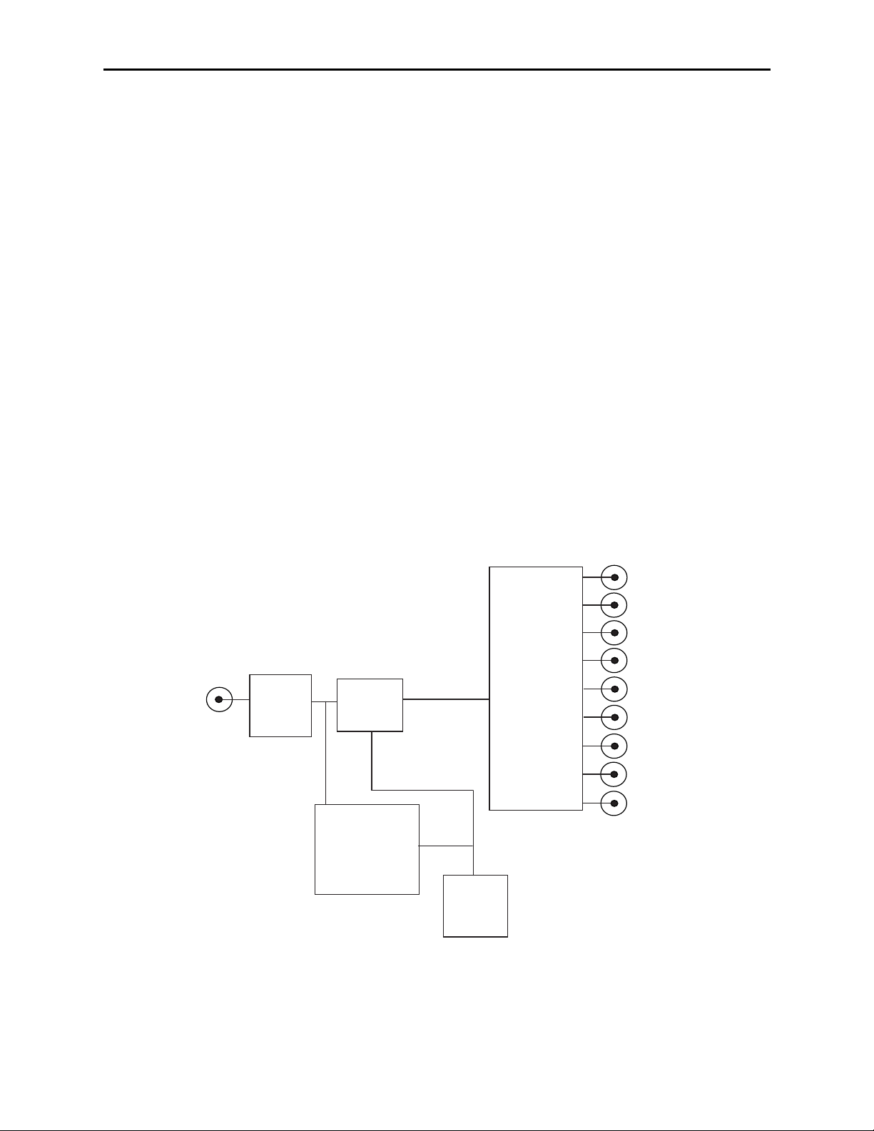
As shown in the block diagram below, the signal passes through an input buffer circuit
then goes on to the gain adjust circuitry. Overall gain can be adjusted locally with the trim
pot on the module front panel or remotely with one of the remote applications as
explained in the Front Panel Controls and Indicators section of this data pack.
Power is derived from the ± 12 volt frame power. It is regulated to the required +5 volts
for the module by on-board regulator. The module is fused with a resettable fuse device. If
the fuse opens due to an overcurrent condition, the module will lose power. After pulling
the module, the fuse will reset automatically requiring no replacement fuse.
The on-board CPU can monitor and report the module ID information (slot location,
software version and board revision) and signal presence detection which can be reported
by the optional frame System Control module to the optional interfaces available.
Model 5150 Analog Video/AES DA
5150 Analog Video DA Functional Block Diagram
5150-2
Input
Output
Input
Buffer
Gain
Adjust
Control
Signal
Detector
Drivers
CPU
Outputs
1
2
3
4
5
6
7
8
9
Page 3
APPLICATIONS
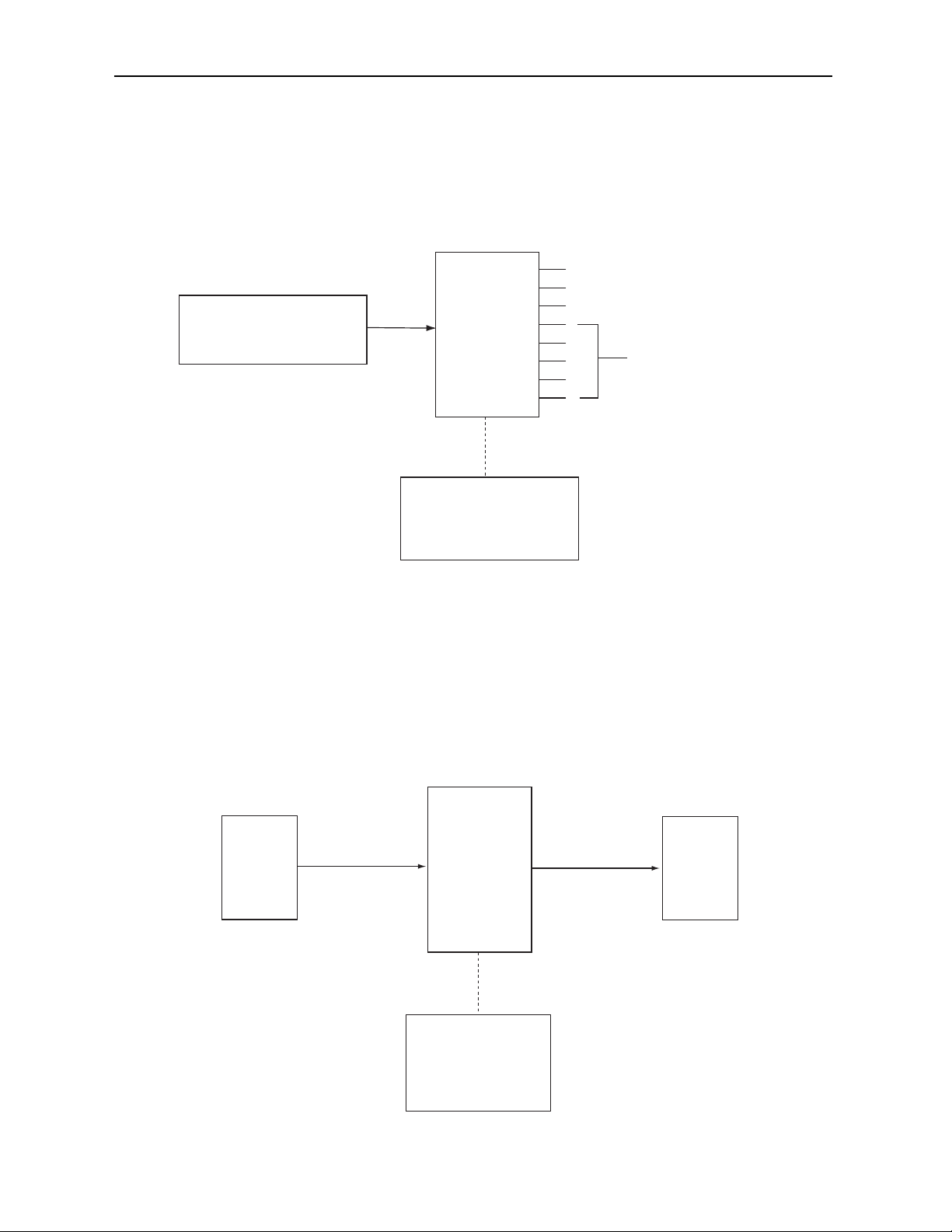
As shown in the example below, the 5150 DA can be utilized to distribute a master
reference source throughout a facility. The master reference genlock signal is inserted into
the 5150 input then distributed to up to nine destinations. The Avenue remote control
system can be set up to report an alarm if there is a loss of the house reference.
The application below shows the 5150 used a video presence detector. The Program
Output signal from a master control device is fed to the 5150 input and then the output of
the DA is sent to the transmitter. An alarm can be set in the Avenue control system to
send an alert if the sync signal to the transmitter is lost.
Model 5150 Analog Video/AES DA
5150-3
5150 Genlock Distribution Application
5150 as Video Presence Detector
BLACK REF
MASTER REFERENCE SOURCE
5150
AVENUE
CONTROL SYSTEM
REPORTS ALARM IF LOSS
OF HOUSE REFERENCE
DISTRIBUTED BLACK SIGNAL 1-9
TO EDIT SUTIE A
TO SWITCHER
TO STLL STORE
TO OTHER EQUIPMENT
5150 ANALOG DA
MASTER CONTROL
PROGRAM OUT
AVENUE
CONTROL SYSTEM
WITH ALARM SET TO DETECT
SIGNAL PRESENCE
AT TRANSMITTER
PROGRAM OUT
TRANSMITTER
Page 4
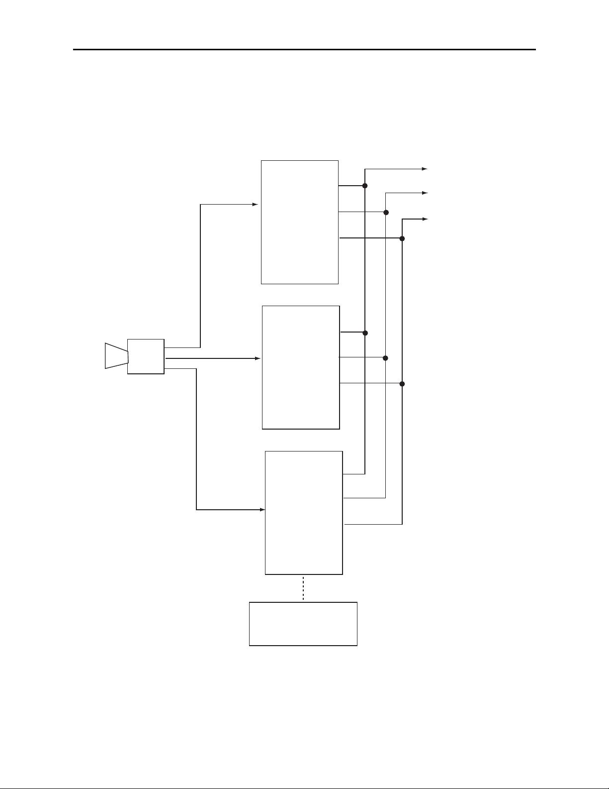
Three 5150 DAs can be utilized as RGB distribution amplifiers as shown in the example
below. The RGB signals from a camera can be distributed throughout the facility to a
switcher, monitor and other equipment.
Model 5150 Analog Video/AES DA
5150 Analog DA Distributing RGB Signals
5150-4
5150 ANALOG DA
TO SWITCHER
R
RED
R
R
5150 ANALOG DA
B
TO EDIT SUTIE
TO MONITOR
RGB CAMERA
BLUE
GREEN
B
B
5150 ANALOG DA
AVENUE
CONTROL SYSTEM
WITH ALARM SET TO DETECT
SYNC PRESENCE
G
G
G
NOTE: VIDEO PRESENCE DETECTION
POSSIBLE ONLY ON SIGNAL WITH
SYNC PRESENT SUCH AS GREEN
Page 5

Model 5150 Analog Video/AES DA
5150-5
INSTALLATION
Plug the 5150 module into any one of the slots in the 1 RU or 3 RU frames and install the
plastic overlay provided onto the corresponding group of rear BNC connectors associated
with the module location. Note that the plastic overlay has an optional adhesive backing
for securing it to the frame. Use of the adhesive backing is only necessary if you would
like the location to be permanent and is not recommended if you need to change module
locations. This module may be hot-swapped (inserted or removed) without powering down
or disturbing performance of the other modules in the system.
CABLING
Refer to the 3 RU and 1 RU backplane diagrams of the module below for cabling instructions. Note that unless stated otherwise, the 1 RU cabling explanations are identical to
those given in the 3 RU diagram.
Connect the analog video
source signal to be distributed
into the Input BNC.
NOTE: This input is self-terminated on the module, if the
module is removed, the input
will become unterminated.
Connect up to nine
analog output destinations
to the Out 1-9 BNCs.
The 15-pin connector is not
used in this application.
3 RU Backplane
1 RU Backplane
5150 DA
Out 9
Out 8
Out 7
Out 6
Out 5
Out 4
Out 3
Out 2
Out 1
Input
Control
Page 6

MODULE CONFIGURATION AND CONTROL
The parameters for each Avenue module must be configured after installation. This can be
done remotely using one of the Avenue remote control options or locally using the module
front panel controls. Each module has a REMOTE/LOCAL switch on the front edge of
the circuit board which must first be set to the control mode you will be using.
The configuration parameter choices for the module will differ between Remote and
Local modes. In Remote mode, the choices are made through software and allow more
selections. The 5150 Parameter Table below summarizes and compares the various con-
figuration parameters that can be set remotely or locally and the default/factory settings.
If you are not using an remote control option, the module parameters must be configured
from the front panel switches. Parameters that have no front panel control will be set to a
default value. The Local switches are illustrated in the Front Panel Controls and
Indicators section following the 5150 Parameter Table.
Avenue module parameters can be configured and controlled remotely from one or both of
the remote control options, the Avenue Touch Screen or the Avenue PC Application. Once
the module parameters have been set remotely, the information is stored on the module
CPU. This allows the module be moved to a different cell in the frame at your discretion
without losing the stored information. Remote configuration will override whatever the
switch settings are on the front edge of the module.
For setting the parameters remotely using the Avenue PC option, refer to the Avenue PC
Remote Configuration section of this document.
For setting the parameters remotely using the Avenue Touch Screen option, refer to the
Avenue Touch Screen Remote Configuration section of this data pack following
Avenue PC.
Model 5150 Analog Video/AES DA
5150-6
5150 Parameter Table
CONTROL
Gain 90-110%
LOCAL
Gain potentiometer:
REMOTE
DEFAULT VALUE
100%
adjust signal ± 10%
Page 7

Front Panel Controls and Indicators
Each front edge indicator and switch setting is explained in the diagram below:
Model 5150 Analog Video/AES DA
Remote/Local switch:
Set to the mode you
will be using.
In OK green LED:
ON indicates presence of valid
analog video signal (meets NTSC
or PAL sync specifications).
OFF indicates sync signal is not
present or invalid (does not meet
NTSC or PAL sync specifications).
Pwr green LED:
Indicates the presence (ON) or
absence (OFF) of power (+5V).
CPU green LED:
OFF:
A power fault or halted CPU
ON:
A halted CPU
FAST BLINK:
CPU Run error
SLOW BLINK:
System OK. (If SPI control is
active from the main frame
System Control Module, all
Run indicators will be syn-
chronized).
GAIN Adjustment:
Adjusts all nine analog
outputs equally.
5150-7
Page 8

Avenue PC Remote Configuration
The Avenue PC remote control menus for this module are illustrated and explained in this
section. Refer to the 5150 Parameter Table for a summary of available parameters that
can be set remotely through the menus illustrated. For more information on using Avenue
PC, refer to the Avenue PC Control Application Software data pack that came with the
option.
5150 Avenue PC Menus
In the Control Menu shown below, set the following parameters:
• Gain - set the gain of the analog output video to the desired setting (90-110
percent).
The following indicator is available in this menu:
• Signal - will indicate the input signal status of the module and will display
No Input or Input OK.
Model 5150 Analog Video/AES DA
5150-8
Page 9
Avenue Touch Screen Remote Configuration
Avenue Touch Screen remote control menus for this module are illustrated and explained
below. Refer to the 5150 Parameter Table for a summary of available parameters that can
be set remotely through the menus illustrated. For more information on using Avenue
Touch Screen, refer to the Avenue Touch Screen data pack that came with the option.
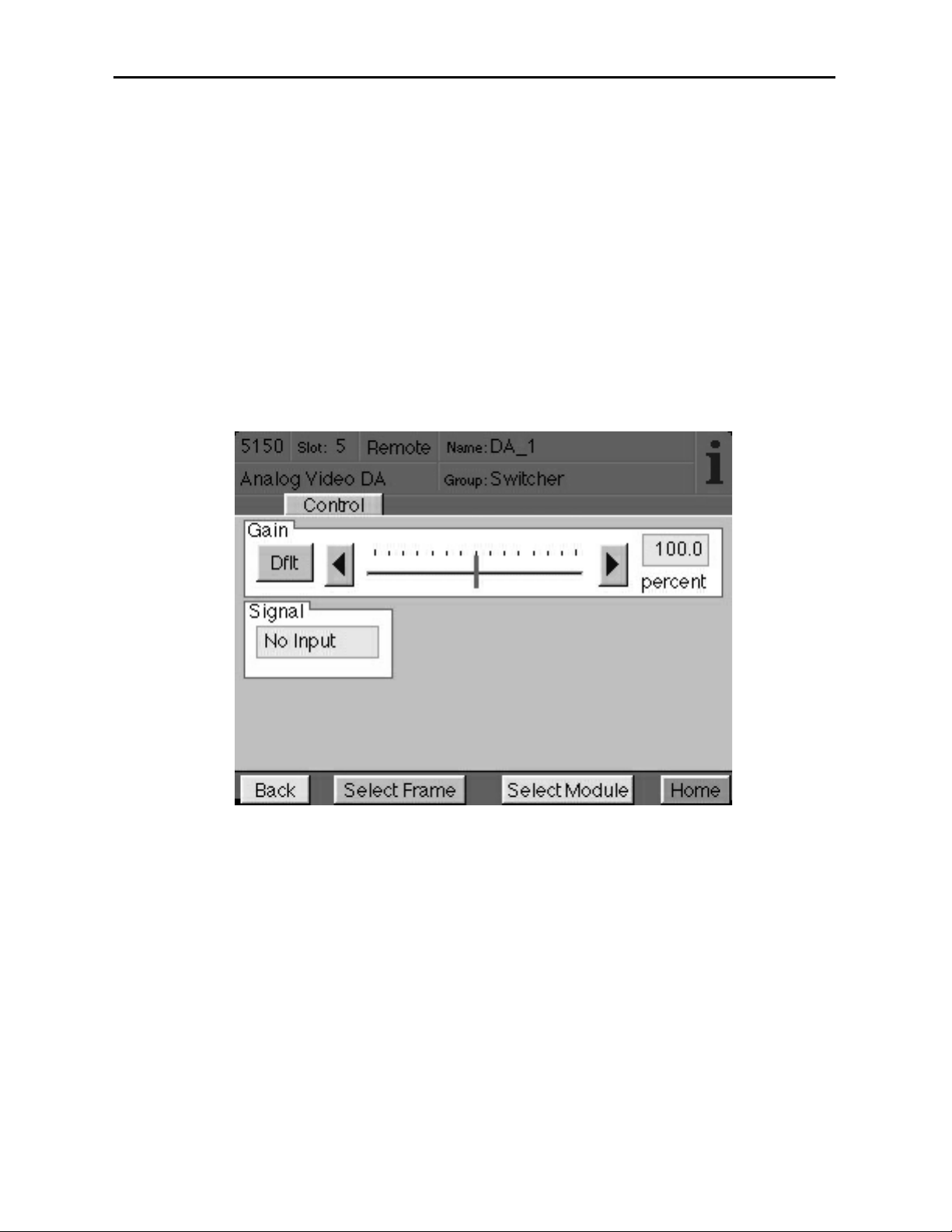
5150 Avenue Touch Screen Menus
In the Control Menu shown below, set the following parameters:
• Gain - set the gain of the analog output video to the desired setting (90-110
percent).
The following indicator is available in this menu:
• Signal - will indicate the input signal status of the module and will display
No Input or Input OK.
Model 5150 Analog Video/AES DA
5150-9
Page 10

TROUBLESHOOTING
To aid in troubleshooting, signal reference levels and presence, power and CPU status can
be easily monitored from the front panel of this module using the indicators explained in
the previous section.
If using the Remote mode, the following status items can be monitored using the Avenue
Touch Screen Control Panel or PC Application:
• Signal presence and validity
• Power status
• Slot ID, Software Version and Board Revision
Refer to the overall troubleshooting tips given below for the 5150 module:
No status lights are lit on front panel:
• Check that frame power is present (green LED{s} on frame power supplies).
• Check that module is firmly seated in frame. Try removing it and plugging
it in again.
Can’t control module:
• Check status of CPU Run green LED. Should be blinking slowly and in
unison with other modules if System Control module is present. If not, try
removing it and plugging it in again.
• System Control module may not be working properly if installed.
No analog signal out of module:
• Check cabling to input of module and presence of valid signal.
No In OK indication:
• Check for presence and validity of sync on input signal.
You may also refer to the technical support section of the Ensemble or Graham-Patten
web sites for the latest information on your equipment at the URLs below:
http://www
.ensembledesigns.com/support
http://www.grahampatten.com
SOFTWARE UPDATING
Software upgrades for each module can be downloaded remotely if the optional System
Control module is installed. These can be downloaded onto your PC and then Avenue PC
will distribute the update to the individual module. (Refer to the Avenue PC documentation for more information) Periodically updates will be posted on our web site. If you do
not have the required System Control Module and Avenue PC, modules can be sent back
to the factory for software upgrades.
Model 5150 Analog Video/AES DA
5150-10
Page 11

Model 5150 Analog Video/AES DA
5150-11
WARRANTYAND FACTORY SERVICE
Warranty
This Module is covered by a five year limited warranty, as stated in the main Preface of
this manual. If you require service (under warranty or not), please contact Ensemble
Designs or Graham-Patten Systems and ask for customer service before you return the
unit. This will allow the service technician to provide any other suggestions for identifying
the problem and recommend possible solutions.
Factory Service
If you return equipment for repair, please get a Return Material Authorization Number
(RMA) from the factory first.
Ship the product and a written description of the problem to:
Ensemble Designs, Inc.
Attention: Customer Service RMA #####
870 Gold Flat Rd.
Nevada City, CA. 95959 USA
(530) 478-1830
Fax: (530) 478-1832
service@endes.com
http://www.ensembledesigns.com
Be sure to put your RMA number on the outside of the box.
OR
Graham-Patten Systems, Inc.
13366 Grass Valley Avenue
Grass Valley, CA 95945
(800) 422-6662 or (530) 273-8412
Fax: (530) 273-7458
service@gpsys.com
http://www.grahampatten.com
Page 12

SPECIFICATIONS
5150 Analog Video DA
Input Signal Description:
Number: One, terminating on module
Signal Type: NTSC/525, PAL/625 composite video or AES audio
Impedance: 75 ohm
Return Loss: 15K - 5 MHz >40 dB
Output Signal Description
Number: Nine
Signal Type: NTSC/525, PAL/625 composite video or AES audio
Impedance: 75 ohm
Return Loss: 15K - 5 MHz >40 dB
DC Follow input: +/- 50 mV
Delay: 10 nS
14 degrees NTSC, 17 degrees PAL
Frequency Response: 300 KHz to 5.5 Mhz
(referenced to 1 MHz) < +/- 0.1 dB
K Factor, 2T Pulse: <0.25% Kp
Differential Phase: 10-90% apl < 0.1 degree
Differential Gain 10-90% apl < 0.15%
General Specifications
Power Consumption: < 3.0 Watts
Temperature Range: 0 to 40 degrees C ambient (all specs met)
Relative Humidity: 0 to 95% noncondensing
Altitude: 0 to 10,000 ft
Fusing: 1.5 Amp PTC resettable fuse
Due to ongoing product development, all specifications subject to change.
Model 5150 Analog Video/AES DA
5150-12
 Loading...