

Page 1

This data pack provides detailed installation, configuration and operation information for
the 5140 Analog EQ Video Distribution Amplifier (DA) as part of the Avenue Signal
Integration System.
The module information in this data pack is organized into the following sections:
• Module Overview
• Applications
• Installation
• Cabling
• Module Configuration and Control
°
Front Panel Controls and Indicators
°
Avenue PC Remote Control
°
Avenue Touch Screen Remote Control
• Troubleshooting
• Software Updating
• Warranty and Factory Service
• Specifications
5140-1
Model 5140
Analog EQ
Video DA
Data Pack
ENSEMBLE
DESIGNS
Revision 1.1 SW v1.0
Page 2

MODULE OVERVIEW
The 5140 provides analog distribution of composite video signals, NTSC and PAL. It can
equalize up to 1000 feet (300 meters) of coaxial cable. The purpose of equalization is to
compensate for the losses that occur when a video signal travels through a length of
coaxial cable. Due to their differing characteristics, different types of cable will require
different equalization networks on the 5140. Cable type must be specified when the
module is ordered.
Input signal validity is displayed locally and can be monitored through the Avenue remote
control options. Gain and EQ parameters can be adjusted locally as well as remotely.
Remote control is accessed via the optional Avenue Touch Screen Control Panel and
Avenue PC Control Applications.
As shown in the block diagram below, the signal passes through the Humblocker™ circuit
then goes on to the equalization circuitry. After that, the signal goes through the gain
adjustment circuitry. Nine outputs are provided.
Power is derived from the ± 12 volt frame power. It is regulated to the required +5 volts
for the module by the on-board regulator. The module is fused with a resettable fuse
device. If the fuse opens due to an overcurrent condition, the module will lose power. After
pulling the module, the fuse will reset automatically requiring no replacement fuse.
The on-board CPU can monitor and report the module ID information (slot location,
software version and board revision) and signal presence detection which can be reported
by the optional frame System Control module to the optional interfaces available.
HumBlocker™
HumBlocker™ technology on the 5140 will automatically process the analog signal to
remove power line hum and other types of interference. This is a superior solution to the
problem of recovering analog signals in noisy environments or in the presence of groundloops. Differential inputs can only provide their full benefit if the shield of the input
signal is never connected to local ground. Asimple patchbay or cable demarcation box can
render differential inputs useless. The HumBlocker feature on the 5140 will actually
identify and cancel power line interference within the video waveform itself.
Because the HumBlocker system is designed specifically for analog composite video, it
must be turned off if the module is being used to distribute other signals (AES, TriLevel
Sync, etc.)
Model 5140 Analog EQ Video DA
5140-2
Outputs
1
2
3
4
5
6
7
8
9
Input
Input
Buffer
Gain
Adjust
Control
Output
Drivers
Signal
Detector
CPU
Page 3

APPLICATIONS
As shown in the example below, the 5140 DA can be utilized to distribute a master
reference source throughout a facility. The master reference genlock signal is inserted into
the 5140 input then distributed to up to nine destinations. The Avenue remote control
system can be set up to report an alarm if there is a loss of house reference.
The application below shows the 5140 used as a video presence detector. The Program
Output signal from a master control device is fed to the 5140 input and then the output of
the DA is sent to the transmitter. An alarm can be set in the Avenue control system to
send an alert if the sync signal to the transmitter is lost.
Model 5140 Analog EQ Video DA
5140-3
5140 Genlock Distribution Application
5140 as Video Presence Detector
BLACK REF
MASTER REFERENCE SOURCE
5140
AVENUE
CONTROL SYSTEM
REPORTS ALARM IF LOSS
OF HOUSE REFERENCE
DISTRIBUTED BLACK SIGNAL 1-9
TO EDIT SUITE A
TO SWITCHER
TO STLL STORE
TO OTHER EQUIPMENT
5140 ANALOG DA
MASTER CONTROL
PROGRAM OUT
AVENUE
CONTROL SYSTEM
WITH ALARM SET TO DETECT
SIGNAL PRESENCE
AT TRANSMITTER
PROGRAM OUT
TRANSMITTER
Page 4

Three 5140 DAs can be utilized as RGB distribution amplifiers as shown in the example
below. The RGB signals from a camera can be distributed throughout the facility to a
switcher, monitor and other equipment.
Model 5140 Analog EQ Video DA
5140 Analog DA Distributing RGB Signals
5140-4
5140 ANALOG DA
TO SWITCHER
R
RED
R
R
TO EDIT SUITE
TO MONITOR
RGB CAMERA
BLUE
GREEN
5140 ANALOG DA
B
B
B
5140 ANALOG DA
G
G
G
AVENUE
CONTROL SYSTEM
WITH ALARM SET TO DETECT
SYNC PRESENCE
NOTE: VIDEO PRESENCE DETECTION
POSSIBLE ONLY ON SIGNAL WITH
SYNC PRESENT SUCH AS GREEN
Page 5

Model 5140 Analog EQ Video DA
5140-5
INSTALLATION
Plug the 5140 module into any one of the slots in the 1 RU or 3 RU frames and install the
plastic overlay provided onto the corresponding group of rear BNC connectors associated
with the module location. Note that the plastic overlay has an optional adhesive backing
for securing it to the frame. Use of the adhesive backing is only necessary if you would
like the location to be permanent and is not recommended if you need to change module
locations. This module may be hot-swapped (inserted or removed) without powering down
or disturbing performance of the other modules in the system.
CABLING
Refer to the 3 RU and 1 RU backplane diagrams of the module below for cabling instructions. Note that unless stated otherwise, the 1 RU cabling explanations are identical to
those given in the 3 RU diagram.
Connect the analog video
source signal to be distributed
into the Input BNC.
NOTE: This input is self-terminated on the module, if the
module is removed, the input
will become unterminated.
Connect up to nine
analog output destinations
to the Out 1-9 BNCs.
The 15-pin connector is not
used in this application.
3 RU Backplane
1 RU Backplane
5140 EQ DA
Out 1
Out 2
Out 3
Out 4
Out 5
Out 6
Out 7
Out 8
Out 9
Input
Out 2
Out 1
5140 EQ DA
Out 4
Out 3
Out 6
Out 5
Out 8
Out 7
Input
Input
Out 9
Page 6

MODULE CONFIGURATION AND CONTROL
The parameters for each Avenue module must be configured after installation. This can be
done remotely using one of the Avenue remote control options or locally using the module
front panel controls. Each module has a REMOTE/LOCAL switch on the front edge of
the circuit board which must first be set to the control mode you will be using.
The configuration parameter choices for the module will differ between Remote and
Local modes. In Remote mode, the choices are made through software and allow more
selections.
If you are not using a remote control option, the module parameters must be configured
from the front panel switches. Parameters that have no front panel control will be set to a
default value. The Local switches are illustrated in the Front Panel Controls and
Indicators section.
Avenue module parameters can be configured and controlled remotely from one or both of
the remote control options, the Avenue Touch Screen or the Avenue PC Application. Once
the module parameters have been set remotely, the information is stored on the module
CPU. This allows the module to be moved to a different cell in the frame at your discretion without losing the stored information. Remote configuration will override whatever
the switch settings are on the front edge of the module.
The 5140 can equalize up to 1000 feet (300 meters) of coaxial cable. Due to their differing
characteristics, different types of cable will require different equalization networks on the
5140. Cable type must be specified when the module is ordered. Alabel on the module
identifies the cable types for which it is appropriate. In addition, the Cable Type
indicator can be viewed through Avenue PC or the TouchScreen control panel.
The purpose of equalization is to compensate for the losses that occur when a video signal
travels through a length of coaxial cable. For lengths under 100 feet these losses are negligible, but for longer cables loss compensation is needed to preserve signal integrity.
Without equalization or compensation, long cables will introduce both gain and frequency
response errors.
Gain Adjustment
The gain errors are easy to correct at either the sending or receiving end of the cable by
simply boosting the overall signal. The frequency response errors are a more complex
problem. Although a long cable will attenuate the entire signal, the higher frequencies
are more significantly affected than the lower frequencies. With composite video, this
means that the chroma information carried in the subcarrier is rolled off with respect to
the luminance content. Adjusting the gain of the path will not correct the frequency
response.
Model 5140 Analog EQ Video DA
5140-6
Page 7

Front Panel Controls and Indicators
Each front edge indicator and switch setting is explained in the diagram below:
Model 5140 Analog EQ Video DA
Remote/Local switch:
Set to the mode you
will be using.
In OK green LED:
ON indicates presence of valid
analog video signal (meets NTSC
or PAL sync specifications).
OFF indicates sync signal is not
present or invalid (does not meet
NTSC or PAL sync specifications).
Pwr green LED:
Indicates the presence (ON) or
absence (OFF) of power (+5V).
CPU green LED:
OFF:
A power fault or halted CPU
ON:
A halted CPU
FAST BLINK:
CPU Run error
SLOW BLINK:
System OK. (If SPI control is
active from the main frame
System Control Module, all
Run indicators will be synchronized).
GAIN Adjustment:
Adjusts all nine analog
outputs equally.
5140-7
5140
Analog
EQ
DA
E
NSEMBLE
DESIGNS
In OK
Run
Pwr
REMOTE
LOCAL
Fine EQ
Gain
Page 8

EQ Adjustment
The 5140 has two controls for cable equalization. The Coarse Eq control selects the
approximate length of the cable to be equalized, while the Fine Eq control is used to
precisely adjust the exact amount of equalization. The total equalization will be the sum
of the Coarse and Fine Eq settings.
The Coarse Eq setting is made through Avenue PC or the TouchScreen when the module
is in Remote. When the module is in Local, the Coarse setting is made with a rotary
switch located in the center of the module. It will most likely be necessary to remove the
module from the frame in order to adjust this switch. The Coarse ranges are:
0 - 200 feet 0 - 60 meters
200-400 feet 60 - 120 meters
400-600 feet 120 - 180 meters
600-800 feet 180 - 240 meters
800-1000 feet 240 - 300 meters
Once the Coarse Eq setting is made, the Fine Eq control is used to bring the total equalization up to the proper amount. The Fine Eq control has an adjustment range of 0 to
250 feet (0 - 75 meters).
The final results should be verified by passing a known, reference signal through the
path. If using color bars, the Fine Eq would then be used to fine-tune the chroma
amplitude setting. ASweep or Multiburst signal can also be used to verify (and adjust if
needed) for flat frequency response.
For setting the parameters remotely using the Avenue PC option, refer to the Avenue PC
Remote Configuration section of this document.
For setting the parameters remotely using the Avenue Touch Screen option, refer to the
Avenue Touch Screen Remote Configuration section of this data pack following
Avenue PC.
Model 5140 Analog EQ Video DA
5140-8
Page 9
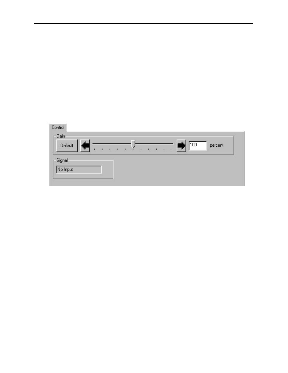
Avenue PC Remote Configuration
The Avenue PC remote control menus for this module are illustrated and explained in this
section. For more information on using Avenue PC, refer to the Avenue PC Control
Application Software data pack that came with the option.
5140 Avenue PC Menus
In the Control Menu shown below, set the following parameters:
• Gain - set the gain of the analog output video to the desired setting (90-110
percent).
The following indicator is available in this menu:
• Signal - will indicate the input signal status of the module and will display
No Input or Input OK.
In the EQ Menu, set the following parameters:
• Cable Type - 1694Aor 8281, or other selection
• Coarse EQ - there are five choices:
0 - 200 feet 0 - 60 meters
200-400 feet 60 - 120 meters
400-600 feet 120 - 180 meters
600-800 feet 180 - 240 meters
800-1000 feet 240 - 300 meters
• Fine EQ - set from 0 to 250 feet
Model 5140 Analog EQ Video DA
5140-9
Page 10

Avenue Touch Screen Remote Configuration
Avenue Touch Screen remote control menus for this module are illustrated and explained
below. For more information on using Avenue Touch Screen, refer to the Avenue Touch
Screen data pack that came with the option.
5140 Avenue Touch Screen Menus
In the Control Menu shown below, set the following parameters:
• Gain - set the gain of the analog output video to the desired setting (90-110
percent).
The following indicator is available in this menu:
• Signal - will indicate the input signal status of the module and will display
No Input or Input OK.
In the EQ Menu, set the following parameters:
• Cable Type - 1694Aor 8281, or other selection
• Coarse EQ - there are five choices:
0 - 200 feet 0 - 60 meters
200-400 feet 60 - 120 meters
400-600 feet 120 - 180 meters
600-800 feet 180 - 240 meters
800-1000 feet 240 - 300 meters
• Fine EQ - set from 0 to 250 feet
Model 5140 Analog EQ Video DA
5140-10
Page 11

TROUBLESHOOTING
To aid in troubleshooting, signal reference levels and presence, power and CPU status can
be easily monitored from the front panel of this module using the indicators explained in
the previous section.
If using the Remote mode, the following status items can be monitored using the Avenue
Touch Screen Control Panel or PC Application:
• Signal presence and validity
• Power status
• Slot ID, Software Version and Board Revision
Refer to the overall troubleshooting tips given below for the 5140 module:
No status lights are lit on front panel:
• Check that frame power is present (green LED{s} on frame power supplies).
• Check that module is firmly seated in frame. Try removing it and plugging
it in again.
Can’t control module:
• Check status of CPU Run green LED. Should be blinking slowly and in
unison with other modules if System Control module is present. If not, try
removing it and plugging it in again.
• System Control module may not be working properly if installed.
No analog signal out of module:
• Check cabling to input of module and presence of valid signal.
No In OK indication:
• Check for presence and validity of sync on input signal.
You may also refer to the technical support section of the Ensemble web site for the latest
information on your equipment at the URL below:
http://www
.ensembledesigns.com/support
SOFTWARE UPDATING
Software upgrades for each module can be downloaded remotely if the optional System
Control module is installed. These can be downloaded onto your PC and then Avenue PC
will distribute the update to the individual module. (Refer to the Avenue PC documentation for more information.) Periodically updates will be posted on our web site. If you do
not have the required System Control Module and Avenue PC, modules can be sent back
to the factory for software upgrades.
Model 5140 Analog EQ Video DA
5140-11
Page 12

Model 5140 Analog EQ Video DA
5140-12
WARRANTYAND FACTORY SERVICE
Warranty
This Module is covered by a five year limited warranty, as stated in the main Preface of
this manual. If you require service (under warranty or not), please contact Ensemble
Designs and ask for customer service before you return the unit. This will allow the
service technician to provide any other suggestions for identifying the problem and
recommend possible solutions.
Factory Service
If you return equipment for repair, please get a Return Material Authorization Number
(RMA) from the factory first.
Ship the product and a written description of the problem to:
Ensemble Designs, Inc.
Attention: Customer Service RMA #####
870 Gold Flat Rd.
Nevada City, CA. 95959 USA
(530) 478-1830
Fax: (530) 478-1832
service@endes.com
http://www.ensembledesigns.com
Be sure to put your RMA number on the outside of the box.
 Loading...