

Page 1
This data pack provides detailed installation, configuration and operation information for
the 5130 Reclocking Serial Distribution Amplifier (DA) with Monitor Outputs as
part of the Avenue Signal Integration System.
The module information in this data pack is organized into the following sections:
• Module Overview
• Applications
• Installation
• Cabling
• Module Configuration and Control
°
Front Panel Controls and Indicators
°
Avenue PC Remote Control
°
Avenue Touch Screen Remote Control
• Troubleshooting
• Software Updating
• Warranty and Factory Service
• Specifications
5130-1
Model 5130
Reclocking Serial DA
with Monitor Outputs
Data Pack
ENSEMBLE
DESIGNS
Revision 2.1 SW v1.1.0
Page 2
MODULE OVERVIEW
The 5130 module is a digital reclocking distribution amplifier (DA) providing one serial
digital input with four serial digital outputs for distributing 270 Mbs serial digital video.
Composite encoding provides four 8-bit composite monitor outputs for monitor viewing
and distribution. Setup on the monitor output is user selectable with an on-board jumper.
Reclocking signal processing performed on the input data stream provides improved jitter
performance and cable equalization of up to 300 meters.
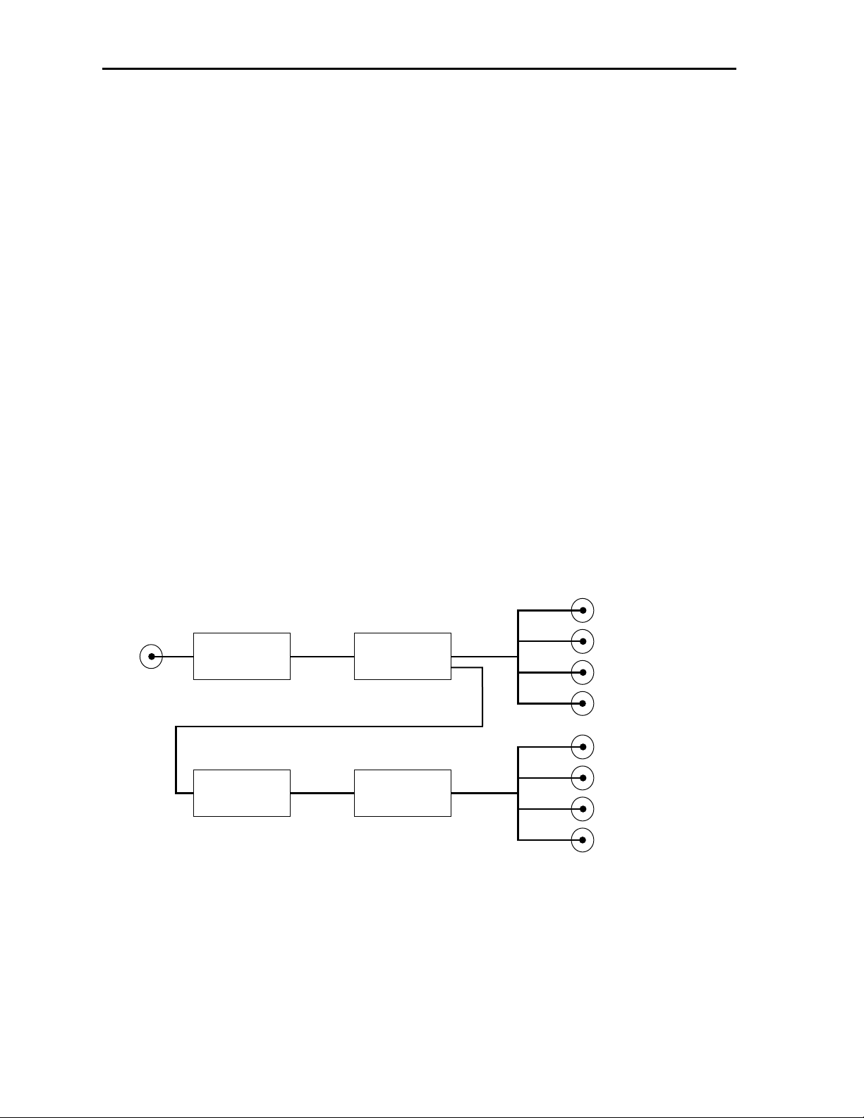
As shown in the block diagram below, the serial input signal passes through a serial
receiver circuit where cable equalization and input monitoring is done. This output passes
to the reclocking circuitry and is then AC coupled to the four serial outputs. The reclocked
video is also routed through a deserializer and is then encoded to composite video for
feeding the four monitor outputs. The input standard (525/625) is detected automatically.
Power is derived from the ± 12 volt frame power. It is regulated to the required +5 volts
for the module by on-board regulator. The module is fused with a resettable fuse device. If
the fuse opens due to an overcurrent condition, the module will lose power. After pulling
the module, the fuse will reset automatically requiring no replacement fuse.
The on-board CPU can monitor and report module ID information (slot location, software
version and board revision), equalization (cable length), and power status to the optional
frame System Control module. This information can be accessed by the user or set to
register an alarm if desired using the remote control options available.
Model 5130 Reclocking Serial DA with Composite Monitor Outputs
5130-2
5130 Reclocking DA with Monitor Outputs Block Diagram
Serial
Receiver
Deserializer
Reclocker
Composite
Encoder
Outputs
Serial Output 1
Serial Output 2
Serial Output 3
Serial Output 4
Moniter Output 1
Moniter Output 2
Moniter Output 3
Moniter Output 4
Page 3
APPLICATIONS
Serial DA with Composite Monitor Outputs
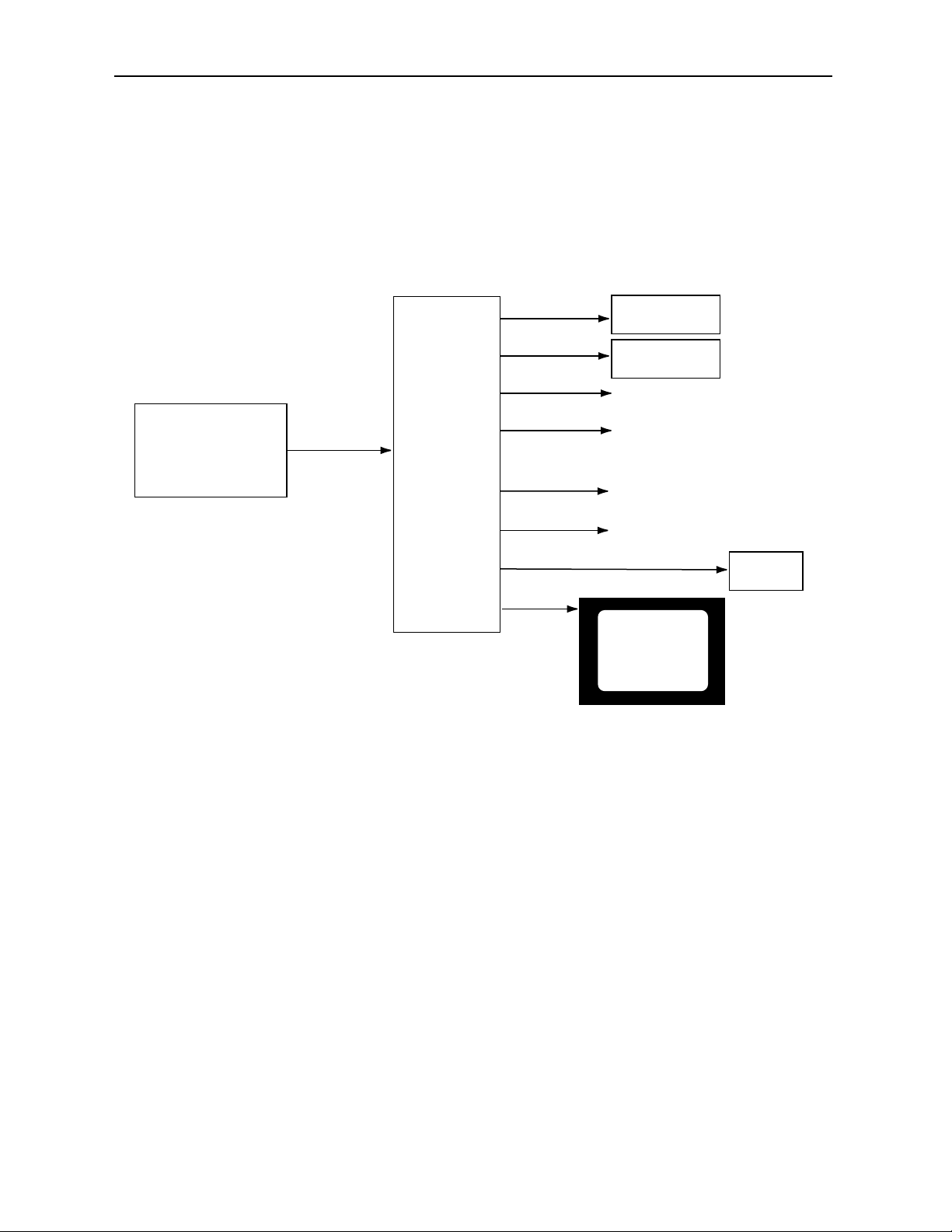
The 5130 is ideal for applications requiring both serial distribution and composite monitoring. The application shown in the block diagram below illustrates how the 5130
module can distribute serial digital video to digital destinations while providing composite
monitoring of these signals with a single module.
Model 5130 Reclocking Serial DA with Composite Monitor Outputs
5130-3
s
5130 Serial DA with Monitor Outputs Application
Digital Beta
SERIAL DIGITAL
VIDEO SWITCHER
Digital Router
Other Digital Video Destination
Other Composite Destinations
MONITOR
Digital Video Out
601 Video Out
5130 DA
Composite
Video Out
VTR
Page 4
Model 5130 Reclocking Serial DA with Composite Monitor Outputs
5130-4
INSTALLATION
Plug the 5130 module into any one of the slots in the 1 RU or 3 RU frame and install the
plastic overlay provided onto the corresponding group of rear BNC connectors associated
with the module location. Note that the plastic overlay has an optional adhesive backing
for securing it to the frame. Use of the adhesive backing is only necessary if you would
like the location to be permanent and is not recommended if you need to change module
locations. This module may be hot-swapped (inserted or removed) without powering down
or disturbing performance of the other modules in the system.
CABLING
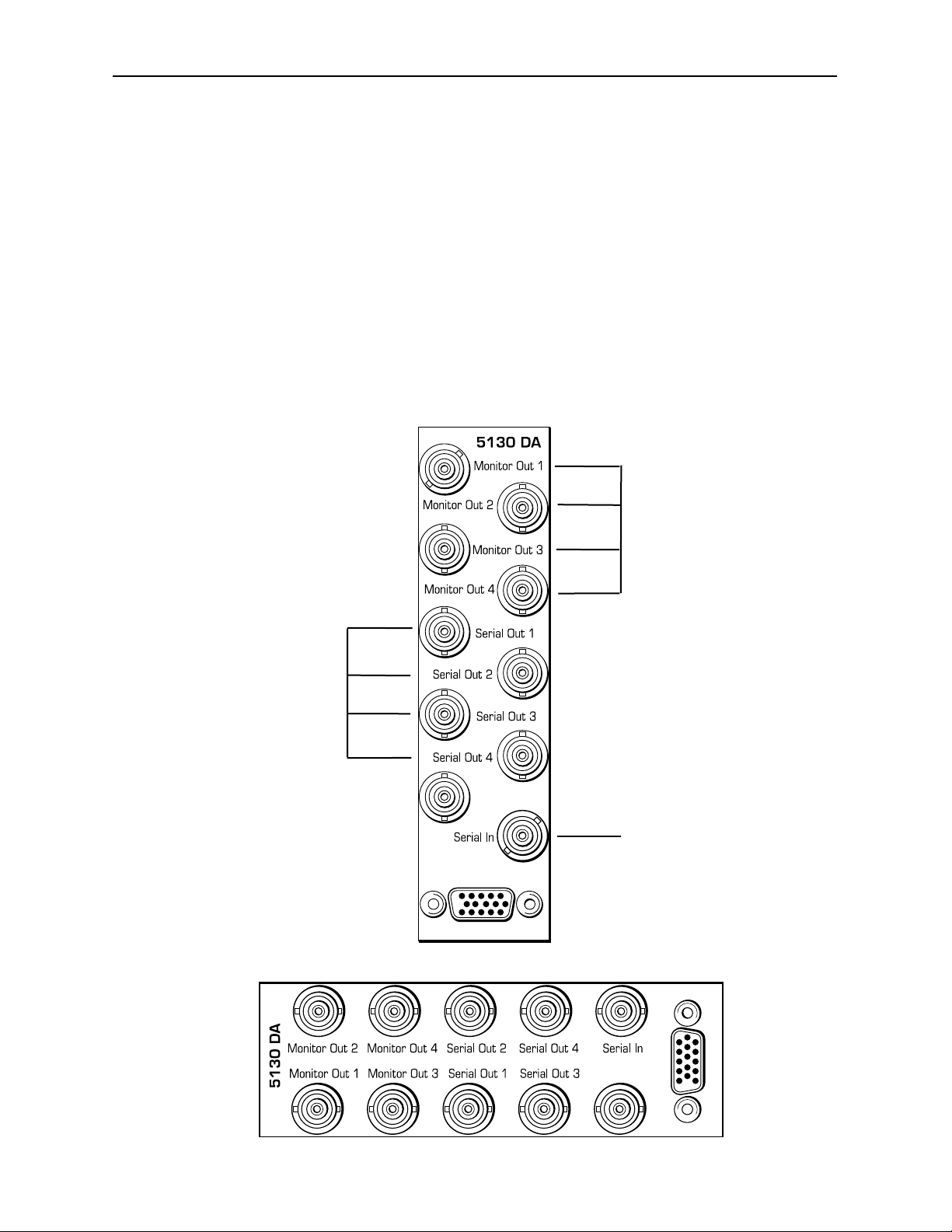
Refer to the 3 RU and 1 RU backplane diagrams of the module below for cabling instructions. Note that unless stated otherwise, the 1 RU cabling explanations are identical to
those given in the 3 RU diagram.
3 RU Backplane
1 RU Backplane
Connect the serial
digital input video signal
to be distributed into the
Serial In BNC.
Connect composite
output destinations to
the Monitor Out 1-4
BNCs.
Connect serial digital
output destinations to
the Serial Out 1-4
BNCs.
Page 5

MODULE CONFIGURATION AND CONTROL
There are no configuration parameters necessary to set on the 5130 module. Module
status is indicated by front panel LEDs or it can be read form remote control menus.
The module indicators are illustrated in the Front Panel Controls and Indicators
section. Avenue module status parameters can be monitored remotely from one or both of
the remote control options, the Avenue Touch Screens or the Avenue PC Application.
For monitoring the parameters remotely using the Avenue PC option, refer to the Avenue
PC Remote Configuration section of this document.
For monitoring the parameters remotely using the Avenue Touch Screen option, refer to
the Avenue Touch Screen Remote Configuration section of this data pack following
Avenue PC.
On-board Configuration
Setup on the monitor outputs when operating in 525 mode can be disabled if desired. To
disable setup, remove the shorting jumper on R11 on the component side of the circuit
board shown in the illustration below.
Model 5130 Reclocking Serial DA with Composite Monitor Outputs
5130-5
Remove Short on R11 for No Setup in 525 Mode
5130 DA
DETAIL
REMOVE SHORT
R11
FOR NO SETUP
Page 6

Front Panel Controls and Indicators
Each front edge indicator and switch setting is shown in the diagram below:
5130-6
Remote/Local switch:
Not used at this time.
Pwr green LED:
Indicates the presence (ON) or
absence (OFF) of power (+5V).
Run green LED:
OFF:
A power fault or halted CPU
ON:
A halted CPU
FAST BLINK:
CPU Run error
SLOW BLINK:
System OK. (If SPI control is
active from the main frame
System Control Module, all
Run indicators will be synchronized.).
EQ OK green LED:
ON when signal is present
and equalized.
OFF when signal is not
present or cable equalization
exceeds maximum cable
length allowed.
525/625 green LED:
ON when EQ is OK and serial
receiver is successfully locked
to either the 525 or 625 data
stream clock.
OFF when EQ is not OK or
serial receiver cannot lock to
either data stream clock.
Model 5130 Reclocking Serial DA with Composite Monitor Outputs
Page 7

Avenue PC Remote Configuration
The Avenue PC remote control status menu for this module is illustrated and explained
below. For more information on using Avenue PC, refer to the Avenue PC Control
Application Software data pack that came with the option.
5130 Avenue PC Menu
The Input menu screen shown below gives the following status information about the
module:
• Equalizer – shows if signal is present and equalized for all outputs.
• Input Status – indicates what line standard the module is locking to.
• Cable Length – indicates current cable length being equalized.
5130-7
Model 5130 Reclocking Serial DA with Composite Monitor Outputs
Page 8

Model 5130 Reclocking Serial DA with Composite Monitor Outputs
Avenue Touch Screen Remote Configuration
The Avenue Touch Screen remote control status menu for this module is illustrated and
explained below. For more information on using Avenue Touch Screen, refer to the Avenue
Touch Screen data pack that came with the option.
5130 Avenue Touch Screen Menus
The Input menu screen shown below gives the following status information about the
module:
• Equalizer – shows if signal is present and equalized for all outputs.
• Input Status – indicates what line standard the module is locking to.
• Cable Length – indicates current cable length being equalized.
5130-8
Page 9

TROUBLESHOOTING
As a troubleshooting aid, the signal equalization and presence, power and CPU status can
be easily monitored from the front panel of this module using the indicators explained in
the previous section.
The following status items can be monitored using the Avenue Touch Screen Control Panel
or PC Application:
• Equalization (cable length)
• Power status
• Slot ID, Software Version and Board Revision
Refer to the overall troubleshooting tips given below for the 5130 module:
No status lights are lit on front panel:
• Check that frame power is present (green LED{s} on frame power supplies).
• Check that module is firmly seated in frame. Try removing it and plugging
it in again.
Can’t control module:
• Check status of CPU Run green LED. Should be blinking slowly and in
unison with other modules if System module is present. If not, try removing
it and plugging it in again.
• System module may not be working properly if installed.
No signal out of module:
• Check status of EQ green LED. Should be lit. If not, check the input signal
for presence and quality.
• Check cabling to input of module.
You may also refer to the technical support section of the Ensemble web site for the latest
information on your equipment at the URL below:
http://www
.ensembledesigns.com/support
SOFTWARE UPDATING
Software upgrades for each module can be downloaded remotely if the optional System
Control module is installed. These can be downloaded onto your PC and then Avenue PC
will distribute the update to the individual module. (Refer to the Avenue PC documentation for more information) Periodically updates will be posted on our web site. If you do
not have the required System Control Module and Avenue PC, modules can be sent back
to the factory for software upgrades.
Model 5130 Reclocking Serial DA with Composite Monitor Outputs
5130-9
Page 10

5130-10
Model 5130 Reclocking Serial DA with Composite Monitor Outputs
WARRANTYAND FACTORY SERVICE
Warranty
This module is covered by a five year limited warranty, as stated in the main Preface of
this manual. If you require service (under warranty or not), please contact Ensemble
Designs and ask for customer service before you return the unit. This will allow the
service technician to provide any other suggestions for identifying the problem and
recommend possible solutions.
Factory Service
If you return equipment for repair, please get a Return Material Authorization Number
(RMA) from the factory first.
Ship the product and a written description of the problem to:
Ensemble Designs, Inc.
Attention: Customer Service RMA #####
870 Gold Flat Rd.
Nevada City, CA. 95959 USA
(530) 478-1830
Fax: (530) 478-1832
service@endes.com
http://www.ensembledesigns.com
Be sure to put your RMA number on the outside of the box.
Page 11

Model 5130 Reclocking Serial DA with Composite Monitor Outputs
SPECIFICATIONS
5130 Video Reclocking DA
Input Signal Description:
Number: One
Signal Type: Serial Digital (SMPTE 259M)
Impedance: 75 ohm
Return Loss: 270 Mbs >15 dB
Maximum Cable: 270 Mbs 300 meters of Belden 8281
Output Signal Description:
Number: Four
Signal Type: Serial Digital (SMPTE 259M)
Impedance: 75 ohm
Return Loss: 270 Mbs >15 dB
Output DC: None (AC coupled)
Composite Monitor Output
Number: Four
Signal Type: NTSC/PAL
Impedance: 75 ohm
Return Loss: > 40dB
Output DC: < +/- 200mV
Response: +/- 0.25 dB
10 KHz to 5.0 MHz
KFactors: <1.5%
Quantization: 9 bits
Setup: User Selectable
General Specifications
Power Consumption: < 5.0 Watts
Temperature Range: 0 to 40 degrees C ambient
Relative Humidity: 0 to 95% noncondensing
Altitude: 0 to 10,000 ft
Fusing: 1.5 Amp PTC resettable fuse
Due to ongoing product development, all specifications subject to change.
5130-11
 Loading...