

Page 1

Model 4500 MPEG Stream Processor
E NSEMBLE
DESIGNS
Model 4500
ASI and SMPTE 310M
Converter and MPEG
Transport Processor
Data Pack
Revision 1.1 SW v2.2.3
www.ensembledesigns.com
4500-1
Page 2

Model 4500 MPEG Stream Processor
Contents
MODULE OVERVIEW 4
DVB-ASI and SMPTE 310M Converter and MPEG Transport Processor 4
Clock Quality and Transmission 5
The Transport Stream Hierarchy 5
Transport Stream Bit Clocks and ATSC Transmissions 6
Importance of clock quality for broadcasting 6
MAJOR FUNCTIONAL CAPABILITIES OF THE 4500 7
Signal Conversion 7
Stream Analysis 7
Clock Cleaner 7
Transport Stream Time Base Corrector 7
BLOCK DIAGRAM 9
INSTALLATION 11
CABLING 11
Status and Alarm Cabling 11
3RU and 1RU Backplane Diagrams 12
4500 Parameter Table 14
Front Panel Controls and Indicators 15
AVENUE PC REMOTE CONFIGURATION 16
4500 Avenue PC Menus 17
Input Menu 17
Stream Menu 18
CRC Menu 19
Program Menu 20
Process Menu 21
www.ensembledesigns.com
4500-2
Page 3

Model 4500 MPEG Stream Processor
Cong Menu 22
AVENUE TOUCH SCREEN REMOTE CONFIGURATION 23
Input Menu 24
Stream Menu 25
CRC Menu 26
Program Menu 27
Process Menu 28
Cong Menu 29
TROUBLESHOOTING 30
SOFTWARE UPDATES 30
WARRANTY AND FACTORY SERVICE 31
Warranty 31
Factory Service 31
SPECIFICATIONS 32
www.ensembledesigns.com
4500-3
Page 4

Model 4500 MPEG Stream Processor
MODULE OVERVIEW
DVB-ASI and SMPTE 310M Converter and MPEG Transport Processor
The 4500 MPEG Transport Stream Processor processes DVB-ASI and SMPTE 310M bitstreams. It
provides stream content analysis with support for Priority 1 and Priority 2 test protocols of the ETR 290
DVB measurement guidelines. As a converter, it can translate ASI to 310M or 310M to ASI. Using the
reference input, the output bitstream can be synchronized to a video or 10 MHz reference signal.
The 4500 module is useful in broadcast and transmission applications. Set the output of the 4500
module to the desired signal type, either ASI or 310M. The module auto-senses what type of signal is
on the input and converts as needed. Advanced conguration in the Avenue Control System allows
choosing which services on the input are passed on to the output.
The built-in transport stream analyzer detects whether the input constitutes a valid signal by checking
for PAT, PMT, and PID packets. In addition to the ETR 290 test protocols, you can congure tests to
dene the minimum number of video and audio packets expected per second in a given service.
Alarms can be generated via SNMP, Avenue PC, and contact closure outputs.
The 4500 acts as a Time Base Corrector to remove jitter and adjust transport streams to the precise,
desired bit rate. The reference input to the 4500 allows the use of either analog video or a 10
MHz signal to synchronize the output of the module. This is of particular importance in broadcast
applications where the quality of the symbol clock – both jitter and accuracy – bears directly on the
modulation process.
Reference to the 4500 can be supplied from an Avenue 7400 or 9400 SPG with GPS Option in order to
provide the ultimate clock accuracy. In this conguration, the 4500 is an ideal solution to frequency
coordination for multi-transmitter systems like Single Frequency Networks (SFN) and mobile/handheld
transmission services.
A CRC and Data Checksum packet can be inserted into the stream by the 4500 to provide data path
integrity testing at downstream points. Monitoring of these special packets can be performed by
a second 4500 or an Avenue 4450, 4455, or 7455 ASI/310 Protection Switch. Data Integrity history
is carried forward through the system to facilitate fault nding. These CRC packets provide an
unequivocal test of data integrity on a transmission link by transmission link basis.
www.ensembledesigns.com
4500-4
Page 5

Model 4500 MPEG Stream Processor
Clock Quality and Transmission
This section addresses the underlying capabilities of the 4500. As background for that discussion, we
will take a quick look at the components of the transport stream.
The Transport Stream Hierarchy
The transport stream works as a hierarchy. At the top of the stream hierarchy is the PAT followed
by PID, PMT and PCR. See the following table for more information about the components of this
hierarchy.
Transport Stream Hierarchy
PAT Program Allocation Table
Goes by about every half a second; •
Shows how many programs are in the stream; •
Indicates which program it is; •
Points to the PID number or PMT for the program. •
PID Packet Identier
PID number for program 1 is 100; PID number for program 2 is 312; •
In the PID stream, there will be a PAT every half a second; •
Every half second, there will be enough packets to add up to 19.3 Mb/s. •
PMT Program Map Table
Indicates how to nd all constituent parts of the transport stream; •
Has description of the program; •
Indicates what the element count is; •
Refers to elemental streams that collectively make up the program; •
elemental stream includes video, audio, closed captions, surround sound;
Indicates where to nd the PCR. •
PCR Program Clock Reference
An on-going set of packets; •
When used properly, the 4500 causes the PCR to be frequency and phase •
locked all the way back to the station.
www.ensembledesigns.com
4500-5
Page 6

Model 4500 MPEG Stream Processor
Transport Stream Bit Clocks and ATSC Transmissions
Having clean, accurate, low-jitter clocks in the MPEG transport stream feeding an ATSC transmitting
system is important. The 4500 oers a method to improve clock quality, thereby improving the overall
performance of the transmission system.
Importance of clock quality for broadcasting
As it aects SDI signals
An SDI signal is a bitstream that contains both information (data) and the pacing (clock) needed to
read it. In order to recover error-free data at the end of a cable, the clocking that is used to construct
the bitstream must be stable and consistent. The eye pattern display on a digital waveform monitor
can be used to verify how well a particular signal source achieves that goal. The better the clock that
underlies the data, the longer a piece of cable that an SDI signal can transit without error.
When a serial clock’s frequency is unwavering and free of phase shifts and noise that would cause the
clock edges to jitter, the data can be easily recovered because the dierence between the symbols (the
ones and zeros in the bitstream) is clear and unambiguous.
As it aects ATSC digital transmission
There are two critical dierences between ATSC and SDI expressed in terms of restrictions in ATSC’s
8 VSB modulation.
The rst dierence is that the channel bandwidth of ATSC is severely restricted compared to an
SDI signal traveling on a piece of coaxial cable. The eective bandwidth of that cable is several
times greater than the fundamental bit rate being transmitted. The consequence of the bandwidth
restriction is that the 8 VSB eye is much smaller than the SDI eye.
The second dierence is ATSC’s use of eight symbols (discrete amplitude levels or voltage levels)
versus two for SDI. At each sampling point (clock) in the ATSC signal, the signal can take on any one of
eight dierent voltage levels (symbols). The digital waveform monitor displays this as a stack of seven
eyes, created by the eight discrete voltage levels possible at the sampling point.
The MPEG encoder generates the digital clock seen in the 8 VSB eye pattern. The frequency accuracy,
purity, and stability of the computer grade clocks is sucient for sending data from point to point on
a coaxial cable. However, these computer grade clocks are not sucient for creating a waveform as
complex as 8 VSB modulation.
Placing an Avenue 4500 MPEG Stream Processor in front of the ATSC Exciter helps the transmitter
present the cleanest possible digital signal.
www.ensembledesigns.com
4500-6
Page 7

Model 4500 MPEG Stream Processor
MAJOR FUNCTIONAL CAPABILITIES OF THE 4500
Signal Conversion
The 4500 converts DVB-ASI to SMPTE 310M or SMPTE 310M to DVB-ASI. Using the reference input, the
output bitstream can be synchronized to a video or 10 MHz reference signal.
Set the output of the 4500 module to the desired signal type. The module auto-senses what type of
signal is on the input and converts as needed. Additionally, it will pass DVB-ASI to DVB-ASI, and SMPTE
310M to SMPTE 310M.
DVB-ASI is a worldwide standard, whereas SMPTE 310M is broadcast in North America only because it
is highly specic to NTSC broadcast standards.
Stream Analysis
The idea of stream analysis in this context is similar to what the 4455 and 7455 can do, yet the
capabilities of the 4500 go above and beyond those products.
The built-in transport stream analyzer detects whether the input constitutes a valid signal by checking
for PAT, PMT, and PID packets. In addition to the ETR 290 test protocols, you can congure tests to
dene the minimum number of video and audio packets expected per second in a given service.
Clock Cleaner
Transport Stream Time Base Corrector
There are reclocking techniques that can be used to reduce jitter in a serial bitstream. But they cannot
correct any underlying frequency error, and ultimately their eectiveness is limited by the bandwidth
inherent in their design.
In contrast, the Avenue 4500 overcomes underlying frequency error by separating the content from
the original clock and generating a new output based upon more accurate and more stable clocks.
Although the data rate of the actual content is constantly varying in response to the compressibility
of that content, the overall data rate is held constant at 19.39 Mb/s. The 4500 accomplishes this by
adjusting the number of null packets (which contain no data) to keep the packet count at precisely
12,894 per second.
www.ensembledesigns.com
4500-7
Page 8

Model 4500 MPEG Stream Processor
As a transport stream arrives at the input of the Avenue 4500, the signal is deserialized and the Data
packets are saved into a buer. The Null packets are discarded.
Guided by a reference clock, Data packets are read from the buer. Null packets are inserted as needed
to bring the total bit rate up to 19.39 Mb/s. The packets are then serialized, using that reference clock,
as either a DVB-ASI or SMPTE 310M signal. All of the original Data is preserved, but the clocks are all
new.
www.ensembledesigns.com
4500-8
Page 9

Model 4500 MPEG Stream Processor
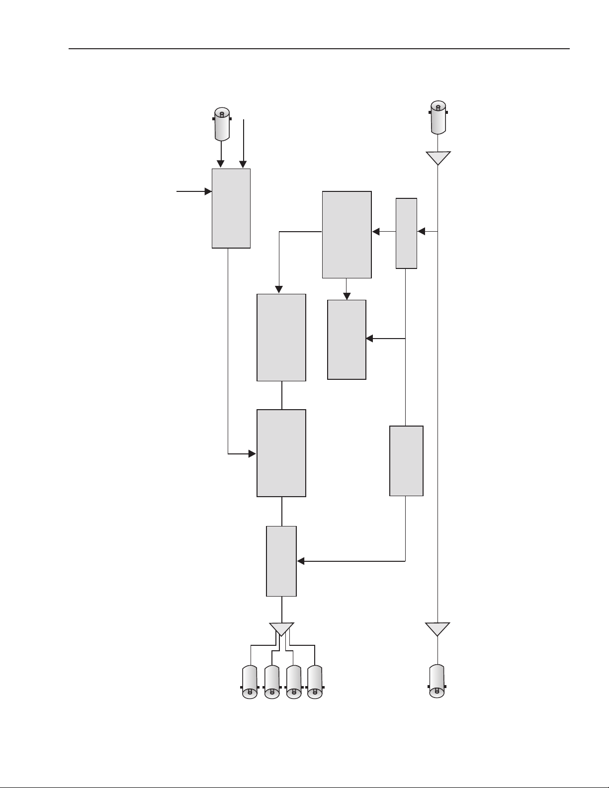
Processed Outputs
CRC Test
Master
Reference
Ext
Ref
Input
Reclocked Loopback Output
DVB-ASI / SMPTE 310M Input
Status and Alarms
SNMP, TCP/IP, GPI
Bit Rate
Clock Generation
CRC History
Management
Stream
Analysis
CRC
Insertion
Packet
Buer
Output
Formatting
Internal
Precision
Reference
BLOCK DIAGRAM
www.ensembledesigns.com
4500 MPEG Stream Processor
Functional Block Diagram, Portrait View
4500-9
Page 10
Processed Outputs
CRC Test
Master
Reference
Ext
Ref
Input
Reclocked Loopback Output
DVB-ASI / SMPTE 310M Input
Status and Alarms
SNMP, TCP/IP, GPI
Bit Rate
Clock Generation
CRC History
Management
Stream
Analysis
CRC
Insertion
Packet
Buer
Output
Formatting
Internal
Precision
Reference
Model 4500 MPEG Stream Processor
Functional Block Diagram, Landscape View
4500 MPEG Stream Processor
www.ensembledesigns.com
4500-10
Page 11

Model 4500 MPEG Stream Processor
INSTALLATION
Plug the 4500 module into any one of the slots in the 1RU or 3RU frame and install the plastic overlay
provided onto the corresponding group of rear BNC connectors associated with the module location.
Note that the plastic overlay has an optional adhesive backing for securing it to the frame. Use of
the adhesive backing is only necessary if you would like the location to be permanent and is not
recommended if you need to change module locations. This module may be hot-swapped (inserted or
removed) without powering down or disturbing performance of the other modules in the system.
CABLING
Refer to the 1RU and 3RU backplane diagrams of the module on the following page for cabling
instructions. Note that unless stated otherwise, the 1RU cabling explanations are identical to those
given in the 3RU diagram.
Status and Alarm Cabling
In addition to full monitoring and access through the control system, the module provides contact
closure status indications through the 15-pin D Control connector on the corresponding rear slot
of the frame. These connections can drive an alarm system or other external monitoring devices
including LEDs. Two override GPI Inputs can also be accessed through the connector. Pinouts for the
status monitoring are given in the illustration on the next page.
Form C relay contacts provide both NO (Normally Open) and NC (Normally Closed) switching to
indicate fault status of the Primary and Secondary inputs and the protection switch output. Both
the NO and NC contacts are simultaneously available on the Control connector. Each output is
independently strappable to provide Ground, current limited +5V (1k Ω resistor), or a Common which
appears on the D connector.
The three relay contacts provide the following status reporting:
Primary Good or Failed• – indicates Primary input status as Good when NO contact is active
(switched to Common).
Secondary Good or Failed• – indicates Secondary input status as Good when NO contact is
active (switched to Common).
Switch Position• – indicates the position of the protect switch as either Primary or Secondary
selected. The normal position corresponds to the Primary feeding the input.
An individual common is provided to each of the relays. For each of the three status relays there is a
3-position jumper on the module which congures the common signal that will be used by that relay.
The choices are as follows:
COM• – uses the user-provided common signal from the Control connector.
+5• – provides a +5V signal through a 1k Ω resistor to the relay common.
Gnd• – uses ground as the relay common.
www.ensembledesigns.com
4500-11
Page 12

Model 4500 MPEG Stream Processor
Out 1
Out 4
Ref In
4500 MSP
Control
Out 2
ASI/310M In
Out 3
Loop Out
PIN FUNCTION
1
1
6
11
5
10
15
Control
2
3
4
5
6
7
8
9
10
11
12
13
14
15
GPI Out 1
GND
GND
GPI Out 4
GPI Out 2
GPI In 1
GPI Out 3
GPI In 2
GND
GPI In 4
GPI In 3
4500 MSP
Out 2
Out 4
Out 1 Ref In
ASI/310MLoop Out
Control
Out 3
3RU and 1RU Backplane Diagrams
Out 1, Out 2, Out 3, Out 4:
Outputs 1 through 4 carry
the processed signal. The
output is selectable and
can be either DVB-ASI at
270 Mb/s or SMPTE 310M.
Set the output from the
Process menu.
3RU Backplane
Loop Outut: The loop output
is reclocked and follows the
ASI/310M Input.
Ref In: The Reference input is
used to correct the ASI and 310M
symbol clock and remove jitter.
The Reference Input can have two
sources: an external source, or
the Frame Master Reference. The
reference input signal can be PAL
or NTSC composite video or 10
MHz 1V P-P sine or square.
www.ensembledesigns.com
1RU Backplane
4500-12
Using the reference input,
the output bitstream can be
synchronized to a video or 10 MHz
reference signal.
ASI/310M In: Can be either DVBASI at 270 Mb/s or SMPTE 310M
signal input. The module autosenses what type of signal is on the
input and converts as needed.
Page 13

Model 4500 MPEG Stream Processor
MODULE CONFIGURATION AND CONTROL
The conguration parameters for each Avenue module must be selected after installation. This can
be done remotely using one of the Avenue remote control options or locally using the module front
panel controls. Each module has a REMOTE/LOCAL switch on the front edge of the circuit board
which must rst be set to the desired control mode.
The conguration parameter choices for the module will dier between Remote and Local modes.
In Remote mode, the choices are made through software and more selections are available. The
4500 Parameter Table on the following page summarizes and compares the various conguration
parameters that can be set remotely or locally and the default/factory settings.
If you are not using a remote control option, the module parameters must be congured from the
front panel switches. Parameters that have no front panel control will be set to a default value. The
Local switches are illustrated in the Front Panel Controls and Indicators section following the 4500
Parameter Table.
Avenue module parameters can be congured and controlled remotely from one or both of the
remote control options, the Avenue Touch Screen or the Avenue PC Application. Once the module
parameters have been set remotely, the information is stored on the module CPU. This allows
the module be moved to a dierent cell in the frame at your discretion without losing the stored
information. Remote conguration will override whatever the switch settings are on the front edge of
the module.
For setting the parameters remotely using the Avenue PC option, refer to the Avenue PC Remote
Conguration section of this document.
For setting the parameters remotely using the Avenue Touch Screen option, refer to the Avenue
Touch Screen Remote Conguration section of this data pack following Avenue PC.
www.ensembledesigns.com
4500-13
Page 14

Model 4500 MPEG Stream Processor
4500 Parameter Table
CONTROL LOCAL REMOTE DEFAULT
Ref Source None Congured Ref
Internal
Input Stream
Program Sel None 1 - 100 1
Output Format ASI/310M switch:
Select ASI (left) to select
ASI as the output, or 310M
(right) to select 310M as the
output.
CRC Insert None O
CRC Err Gen None O
Congured Ref None Master Ref
CRC PID None 4000 - 8000 4000
DVB-ASI
SMPTE 310M
On - Forward
On - No Fwd
CRC Error Only
CSum Error Only
CRC & CSum Error
External Ref
Congured Ref
DVB-ASI
O
O
Master Ref
www.ensembledesigns.com
4500-14
Page 15

Model 4500 MPEG Stream Processor
DVB-ASI
310M
Remote
Local
Run
Pwr
4500
MPEG
Stream
Processor
Ref
Input
ASI/310M
Genlock
On
Out
Front Panel Controls and Indicators
Each front edge indicator and switch setting of the 4500 is shown in the diagram below:
DVB-ASI green LED:
ON when input is DVB-ASI.
OFF when no DVB-ASI signal is
present in the input. The module
auto-senses what type of signal
is on the input and converts as
needed.
310M green LED:
ON when input is 310M.
OFF when no 310M signal is
present in the input. The module
auto-senses what type of signal
is on the input and converts as
needed.
Ref green LED:
ON when Reference input is
detected and locked.
OFF when no Reference input is
detected.
ASI/310M switch:
Select ASI (left) to select ASI as
the output, or 310M (right) to
select 310M as the output.
Remote/Local switch:
Set to the mode you wish to use:
Up for Remote mode and down
for Local mode.
Run green LED:
OFF A power fault or halted CPU
ON A halted CPU
FAST BLINK CPU Run error
SLOW BLINK System OK. (If SPI
control is active from the main
frame System Control Module, all
Run indicators will be
synchronized.)
Pwr green LED:
Indicates the presence (ON) or
absence (OFF) of power (+5V).
www.ensembledesigns.com
4500-15
Page 16

Model 4500 MPEG Stream Processor
AVENUE PC REMOTE CONFIGURATION
The Avenue PC remote control status menus for the 4500 module are illustrated and explained below.
Refer to the 4500 Parameter Table for a summary of available parameters that can be set remotely
through the menus illustrated. For more information on using Avenue PC, refer to the Avenue PC
Control Application Software data pack that came with the option.
Parameter elds that are grayed out can indicate one of the following conditions:
An option is not installed. •
The function is not active. •
The module is locked. •
The User Level set with Avenue PC is not accessible from the current User Level. •
www.ensembledesigns.com
4500-16
Page 17

Model 4500 MPEG Stream Processor
4500 Avenue PC Menus
Input Menu
The Input menu screen shown below displays the Input Status, Reference Source and Reference
Status. This is useful for verifying which signal is present in the input and which reference source is
selected. The built-in transport stream analyzer detects whether the input constitutes a valid signal by
checking for PAT, PMT, and PID packets.
Input Status• – Auto-detects which input signal is present. Can be either DVB-ASI at 270 Mb/s
or SMPTE 310M. If there is no input signal present, this eld will show “No input.”
Ref Source• – Shows the selected Reference Source. Available selections are: Congured Ref,
Internal, and Input Stream.
Congured Ref means that the Ref Status eld will reect what has been selected under the
Cong menu.
Internal means that the Ref Status eld shows Internal.
Input Stream means that the Ref Status eld reects the signal present in the Input, either ASI
Input or SMPTE 310M Input.
Ref Status• – Displays one of the following:
No Reference, SD525 Sync, SD625 Sync, 10 MHz, ASI Input, 310M Input, Internal, Unknown.
www.ensembledesigns.com
4500-17
Page 18

Model 4500 MPEG Stream Processor
Stream Menu
The Stream menu shown below displays information about the signal stream for monitoring
purposes. All the elds are read-only.
Stream Status• – Status indicators for the signal stream are Good, Not Present, and No Input.
Packet Length• – Indicates the packet length in bytes. Can be 188, 204 or 208.
PAT per Sec• – Shows how many Program Allocation Tables are present in the signal per
second.
Stream Rate• – Shows the stream rate in terms of kilobytes per second.
Null Rate• – Indicates the current rate of Null packets being inserted into the signal stream in
terms of kilobytes per second.
Null Min• and Null Max – These elds show the range of minimum and maximum Null packets
in the signal stream in terms of kilobytes per second.
www.ensembledesigns.com
4500-18
Page 19

Model 4500 MPEG Stream Processor
CRC Menu
The CRC menu shown below allows you to monitor the status of the Cyclic Redundancy Check (CRC)
data in the stream. A CRC and Data Checksum packet can be inserted into the stream by the 4500 to
provide data path integrity testing at downstream points. These CRC packets test the data integrity on
a transmission link by transmission link basis.
Input CRC• – Possible values are: None, Good, CRC Bad, CSum Bad, CRC/CSum Bad.
CRC ErrSec• – The CRC error rate per second.
CSum ErrSec• – The Checksum error rate per second.
Hop Count• – The number of times that the signal has gone from one 4500 to another.
For example, a 4500 module upstream may insert CRC packets which are detected by a
downstream 4500 module.
UpStream CRC• – Indicates whether there has been an error in the signal upstream.
www.ensembledesigns.com
4500-19
Page 20

Model 4500 MPEG Stream Processor
Program Menu
The Program menu shown below allows you to select a program and monitor its program status,
Program Map Tables per second, Program Clock References per second, video rate and audio rate.
Program Sel• – Select a program by clicking the arrows or entering a value directly in the eld.
(Touch Screen: Select a program by pressing the arrows.) Available values are 1 to 100.
Program Status• – Reports the program status. Possible values are: No Input, No Stream, No
PAT, No PMT, No Video, No Audio, Good.
PMT per Sec• – Reports the number of Program Map Tables detected in the signal per second.
PCR per Sec• – Reports the number of Program Clock References detected in the signal per
second.
Video Rate• – Reports the Video Rate in terms of kilobytes per second.
Audio Rate• – Reports the Audio Rate in terms of kilobytes per second.
www.ensembledesigns.com
4500-20
Page 21

Model 4500 MPEG Stream Processor
Process Menu
The Process menu allows you to select which Output Format you want (DVB-ASI or SMPTE 310M) for
BNC Outputs 1 through 4 for the processed signal. You can also congure how you want to treat CRC
insertion and CRC and Checksum error generation using the drop-down menus CRC Insert and CRC
Error Generator. Data Integrity history is carried forward through the system to facilitate fault nding.
Output Format• – Set the output of the 4500 module to the desired signal type, either DVB-ASI
or SMPTE 310M.
CRC Insert• – Available selections are: O, On - Forward, On - No Fwd.
O means that no CRC packets are inserted into the signal.
On - Forward means that CRC packets are inserted into the signal and also forwarded on so
that they can be detected downstream.
On - No Fwd means that CRC packets are inserted into the signal but are not forwarded on.
CRC Err Gen• – Available selections are: O, CRC Error Only, CSum Error Only, CRC & CSum Error.
www.ensembledesigns.com
4500-21
Page 22

Model 4500 MPEG Stream Processor
Cong Menu
The Cong menu allows you to select which reference you want to use (Master Ref or External Ref).
The Ref In eld reports the type of reference signal coming in. You can also select an option for the
CRC PID control (from 4000 to 8000).
Congured Ref• – Select either Master Ref or External Ref.
Master Ref means that the module is taking its reference signal from the Avenue Frame itself.
External Ref means that the module is taking its reference from an external source, such as an
Avenue 7400 Test Signal and Sync Pulse Generator installed in the Avenue Frame.
Ref In• – Reports the type of reference signal coming in.
Possible values are: No Reference, 525 Composite, 625 Composite, 10 MHz.
CRC PID• – Use the arrow buttons to select a value from 4000 to 8000. You can also enter a
number directly in the eld. This is commonly a “set and forget” type of conguration. Use it to
select the PID you want to use for inserting CRCs or Checksum, replacing Null packets.
The Cong menu showing the available selections for the
Congured Ref control.
The Cong menu showing the upper limit that can be selected for
the CRC PID control.
www.ensembledesigns.com
4500-22
Page 23

Model 4500 MPEG Stream Processor
AVENUE TOUCH SCREEN REMOTE CONFIGURATION
The Avenue Touch Screen remote control status menus for this module are illustrated and explained
below. Refer to the 4500 Parameter Table for a summary of available parameters that can be set
remotely through the menus illustrated. For more information on using Avenue Touch Screen, refer to
the Avenue Touch Screen data pack.
Parameter elds that are grayed out can indicate one of the following conditions:
An option is not installed. •
The function is not active. •
The module is locked. •
The User Level set with Avenue PC is not accessible from the current User Level. •
www.ensembledesigns.com
4500-23
Page 24

Model 4500 MPEG Stream Processor
Input Menu
The Input menu screen shown below displays the Input Status, Reference Source and Reference
Status. This is useful for verifying which signal is present in the input and which reference source is
selected. The built-in transport stream analyzer detects whether the input constitutes a valid signal by
checking for PAT, PMT, and PID packets.
Input Status• – Auto-detects which input signal is present. Can be either DVB-ASI at 270 Mb/s
or SMPTE 310M. If there is no input signal present, this eld will show “No input.”
Ref Source• – Shows the selected Reference Source. Available selections are: Congured Ref,
Internal, and Input Stream.
Congured Ref means that the Ref Status eld will reect what has been selected under the
Cong menu.
Internal means that the Ref Status eld shows Internal.
Input Stream means that the Ref Status eld reects the signal present in the Input, either ASI
Input or SMPTE 310M Input.
Ref Status• – Displays one of the following:
No Reference, SD525 Sync, SD625 Sync, 10 MHz, ASI Input, 310M Input, Internal, Unknown.
www.ensembledesigns.com
4500-24
Page 25

Model 4500 MPEG Stream Processor
Stream Menu
The Stream menu shown below displays information about the signal stream for monitoring
purposes. All the elds are read-only.
Stream Status• – Status indicators for the signal stream are Good, Not Present, and No Input.
Packet Length• – Indicates the packet length in bytes. Can be 188, 204 or 208.
PAT per Sec• – Shows how many Program Allocation Tables are present in the signal per
second.
Stream Rate• – Shows the stream rate in terms of kilobytes per second.
Null Rate• – Indicates the current rate of Null packets being inserted into the signal stream in
terms of kilobytes per second.
Null Min• and Null Max – These elds show the range of minimum and maximum Null packets
in the signal stream in terms of kilobytes per second.
www.ensembledesigns.com
4500-25
Page 26

Model 4500 MPEG Stream Processor
CRC Menu
The CRC menu shown below allows you to monitor the status of the Cyclic Redundancy Check (CRC)
data in the stream. A CRC and Data Checksum packet can be inserted into the stream by the 4500 to
provide data path integrity testing at downstream points. These CRC packets test the data integrity on
a transmission link by transmission link basis.
Input CRC• – Possible values are: None, Good, CRC Bad, CSum Bad, CRC/CSum Bad.
CRC ErrSec• – The CRC error rate per second.
CSum ErrSec• – The Checksum error rate per second.
Hop Count• – The number of times that the signal has gone from one 4500 to another.
For example, a 4500 module upstream may insert CRC packets which are detected by a
downstream 4500 module.
UpStream CRC• – Indicates whether there has been an error in the signal upstream.
www.ensembledesigns.com
4500-26
Page 27

Model 4500 MPEG Stream Processor
Program Menu
The Program menu shown below allows you to select a program and monitor its program status,
Program Map Tables per second, Program Clock References per second, video rate and audio rate.
Program Sel• – Select a program by clicking the arrows or entering a value directly in the eld.
(Touch Screen: Select a program by pressing the arrows.) Available values are 1 to 100.
Program Status• – Reports the program status. Possible values are: No Input, No Stream, No
PAT, No PMT, No Video, No Audio, Good.
PMT per Sec• – Reports the number of Program Map Tables detected in the signal per second.
PCR per Sec• – Reports the number of Program Clock References detected in the signal per
second.
Video Rate• – Reports the Video Rate in terms of kilobytes per second.
Audio Rate• – Reports the Audio Rate in terms of kilobytes per second.
www.ensembledesigns.com
4500-27
Page 28

Model 4500 MPEG Stream Processor
Process Menu
The Process menu allows you to select which Output Format you want (DVB-ASI or SMPTE 310M) for
BNC Outputs 1 through 4 for the processed signal. You can also congure how you want to treat CRC
insertion and CRC and Checksum error generation using the drop-down menus CRC Insert and CRC
Error Generator. Data Integrity history is carried forward through the system to facilitate fault nding.
Output Format• – Set the output of the 4500 module to the desired signal type, either DVB-ASI
or SMPTE 310M.
CRC Insert• – Available selections are: O, On - Forward, On - No Fwd.
O means that no CRC packets are inserted into the signal.
On - Forward means that CRC packets are inserted into the signal and also forwarded on so
that they can be detected downstream.
On - No Fwd means that CRC packets are inserted into the signal but are not forwarded on.
CRC Err Gen• – Available selections are: O, CRC Error Only, CSum Error Only, CRC & CSum Error.
www.ensembledesigns.com
4500-28
Page 29

Model 4500 MPEG Stream Processor
Cong Menu
The Cong menu allows you to select which reference you want to use (Master Ref or External Ref).
The Ref In eld reports the type of reference signal coming in. You can also select an option for the
CRC PID control (from 4000 to 8000).
Congured Ref• – Select either Master Ref or External Ref.
Master Ref means that the module is taking its reference signal from the Avenue Frame itself.
External Ref means that the module is taking its reference from an external source, such as an
Avenue 7400 Test Signal and Sync Pulse Generator installed in the Avenue Frame.
Ref In• – Reports the type of reference signal coming in.
Possible values are: No Reference, 525 Composite, 625 Composite, 10 MHz.
CRC PID• – Use the arrow buttons to select a value from 4000 to 8000. You can also enter a
number directly in the eld. This is commonly a “set and forget” type of conguration. Use it to
select the PID you want to use for inserting CRCs or Checksum, replacing Null packets.
www.ensembledesigns.com
4500-29
Page 30

Model 4500 MPEG Stream Processor
TROUBLESHOOTING
As a troubleshooting aid, reference signal status and presence, as well as power and CPU status can be
easily monitored from the front panel of the 7465 module using the front panel indicators.
Refer to the troubleshooting tips below:
Can’t control module
Check status of CPU Run green LED. Should be blinking slowly and in unison with other •
modules if System module is present. If not, try removing it and plugging it in again to be sure
it is seated properly.
System module may not be working properly if installed. •
Module remote controls are grayed out
Module is locked or access to module controls is restricted by User Level. •
No signal out of module
Check status of Active LEDs. Primary or Secondary should be lit. If not, check the inputs for •
signal presence and quality.
Check cabling to input of the module. •
Please also refer to the technical support section of the Ensemble Designs web site for the latest
information on your equipment at the URL below:
http://www.ensembledesigns.com/support
SOFTWARE UPDATES
Software updates for each module can be downloaded remotely if the optional System Control
module is installed. These can be downloaded onto your PC, then Avenue PC will distribute the update
to the individual module. (Refer to the Avenue PC documentation for more information) Updates are
periodically posted on the Ensemble Designs web site. If you do not have the required System Control
Module and Avenue PC, modules can be sent back to the factory for software upgrades.
www.ensembledesigns.com
4500-30
Page 31

Model 4500 MPEG Stream Processor
WARRANTY AND FACTORY SERVICE
Warranty
This product is covered by a ve year limited warranty. If you require service (under warranty or not),
please contact Ensemble Designs and ask for customer service before you return this product. This
will allow the service technician to provide any other suggestions for identifying the problem and
recommend possible solutions.
Factory Service
If you return equipment for repair, please get a Return Material Authorization Number (RMA) from the
factory rst.
Ship the product and a written description of the problem to:
Ensemble Designs, Inc.
Attention: Customer Service RMA #####
870 Gold Flat Rd.
Nevada City, CA. 95959 USA
(530) 478-1830
Fax: (530) 478-1832
Ensemble Designs customer service email address:
service@ensembledesigns.com
Website: http://www.ensembledesigns.com
Be sure to put your RMA number on the outside of the box.
www.ensembledesigns.com
4500-31
Page 32

Model 4500 MPEG Stream Processor
SPECIFICATIONS
Input Signals
Number One
Signal Type DVB-ASI at 270 Mb/s or SMPTE 310M
Loopback
Number One
Impedence 75 Ω
Output Signal (processed)
Number Four
Signal Type DVB-ASI at 270 Mb/s or SMPTE 310M, selectable
Impedance 75 Ω
Reference Input
Number Two: External or Frame Master Reference
Signal Type PAL or NTSC composite video or 10 MHz 1V P-P sine
or square
Return Loss >40 dB (applies to external ref input)
Signal Analysis
ETR 290 Compliant, Priority 1 and Priority 2
Data integrity CRC test
Clock Accuracy
Internal Reference (TCXO)
Freq Error <0.1 ppm
<10
-7
External reference follows Ref Source
10
-12
possible with GPS grade reference
General Specications
Power Consumption <7.0 watts
Temperature Range 0 to 40°C ambient
(all specs met)
Relative Humidity 0 to 95%, noncondensing
Altitude 0 to 10,000 ft
www.ensembledesigns.com
4500-32
 Loading...