

Page 1
This data pack provides detailed installation, configuration and operation information for
the 4110 DVB-ASI Distribution Amplifier (DA) as part of the Avenue Signal
Integration System.
The module information in this data pack is organized into the following sections:
• Module Overview
• Applications
• Installation
• Cabling
• Module Configuration and Control
°
Front Panel Controls and Indicators
°
Avenue PC Remote Control
°
Avenue Touch Screen Remote Control
• Troubleshooting
• Software Updating
• Warranty and Factory Service
• Specifications
4110-1
Model 4110
DVB-ASI DA
Data Pack
ENSEMBLE
DESIGNS
Revision 1.1 SW v1.1.0
Page 2
MODULE OVERVIEW
The 4110 DVB-ASI DAprovides distribution of a DVB-ASI, DVB-SSI or SMPTE 310M
input signal to eight outputs. The module handles data rates from 19.39 Mb/s to 270 Mb/s.
Signal presence detection and cable equalization is provided on the module.
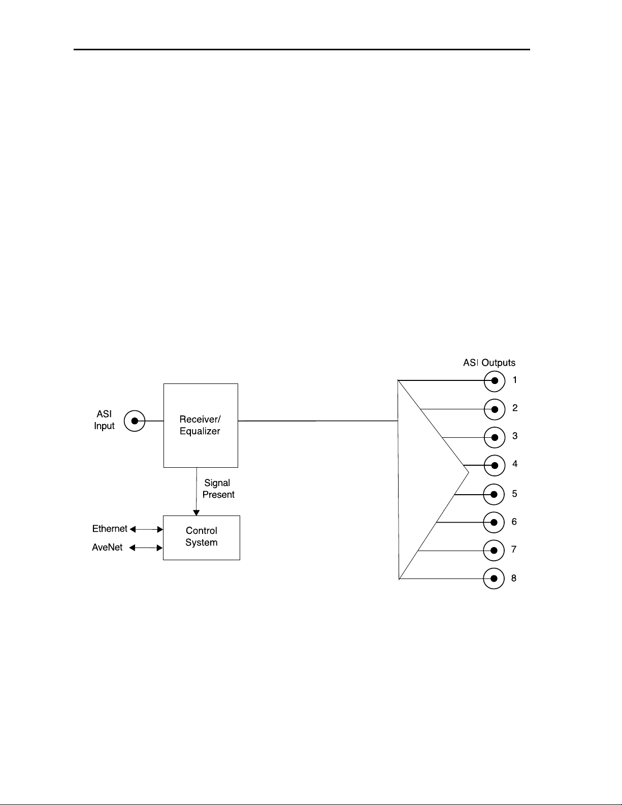
As shown in the block diagram below, the input signal passes through a receiver/equalizer
circuit. The signal strength of the equalized output is monitored by the module processor
for cable equalization and EQ warning information available to the user via the optional
Avenue control interfaces. The DVB-ASI outputs are buffered then AC coupled to the
BNCs on the rear of the frame providing eight serial outputs for distribution.
Power is derived from the ± 12 volt frame power. It is regulated to the required +5 volts
for the module by on-board regulator. The module is fused with a resettable fuse device. If
the fuse opens due to an overcurrent condition, the module will lose power. After pulling
the module, the fuse will reset automatically requiring no replacement fuse.
Module ID information (slot location, software version and board revision) can be
monitored by the optional frame System Control module and read using the optional
interfaces available.
Model 4110 DVB-ASI DA
4110 DVB-ASI DA Functional Block Diagram
4110-2
Page 3
APPLICATIONS
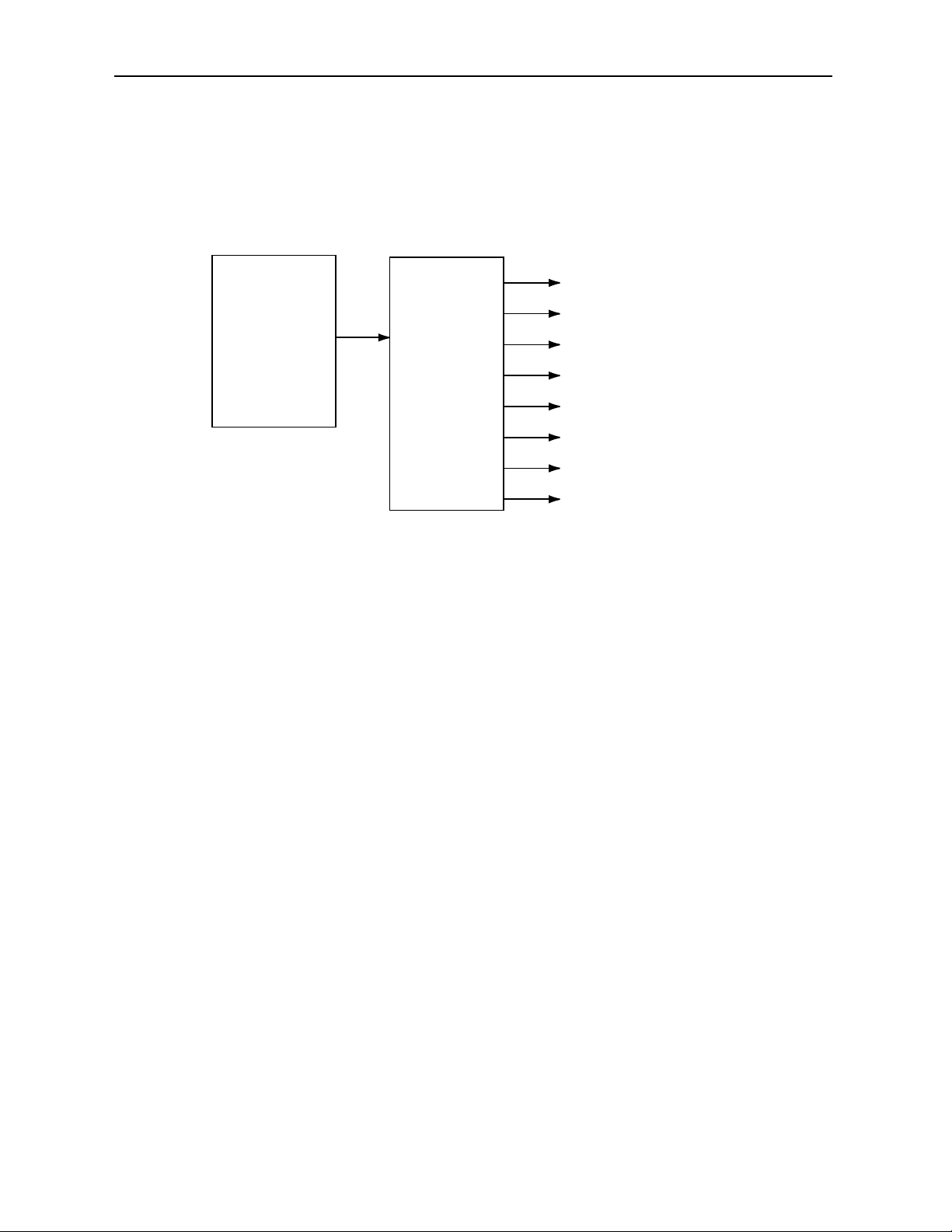
The 4110 DVB-ASI Distribution Amplifier is ideal for applications where distribution of
ASI signals from a server to other ASI-compatible destinations is required. Use the 4110
module to distribute signals as shown in the example below.
Model 4110 DVB-ASI DA
4110-3
4110 DVB-ASI Distribution Amplifier and 4430 ASI Router Application
SERVER
4110 ASI DA
ENCODERS
4430 ASI ROUTER
ASI OUT
ASI IN
OTHER SERVERS
OTHER ASI DESTINATIONS
Page 4
Model 4110 DVB-ASI DA
4110-4
INSTALLATION
Plug the 4110 module into any one of the slots in the 1 RU or 3 RU frame and install the
plastic overlay provided onto the corresponding group of rear BNC connectors associated
with the module location. Note that the plastic overlay has an optional adhesive backing
for securing it to the frame. Use of the adhesive backing is only necessary if you would
like the location to be permanent and is not recommended if you need to change module
locations. This module may be hot-swapped (inserted or removed) without powering down
or disturbing performance of the other modules in the system.
CABLING
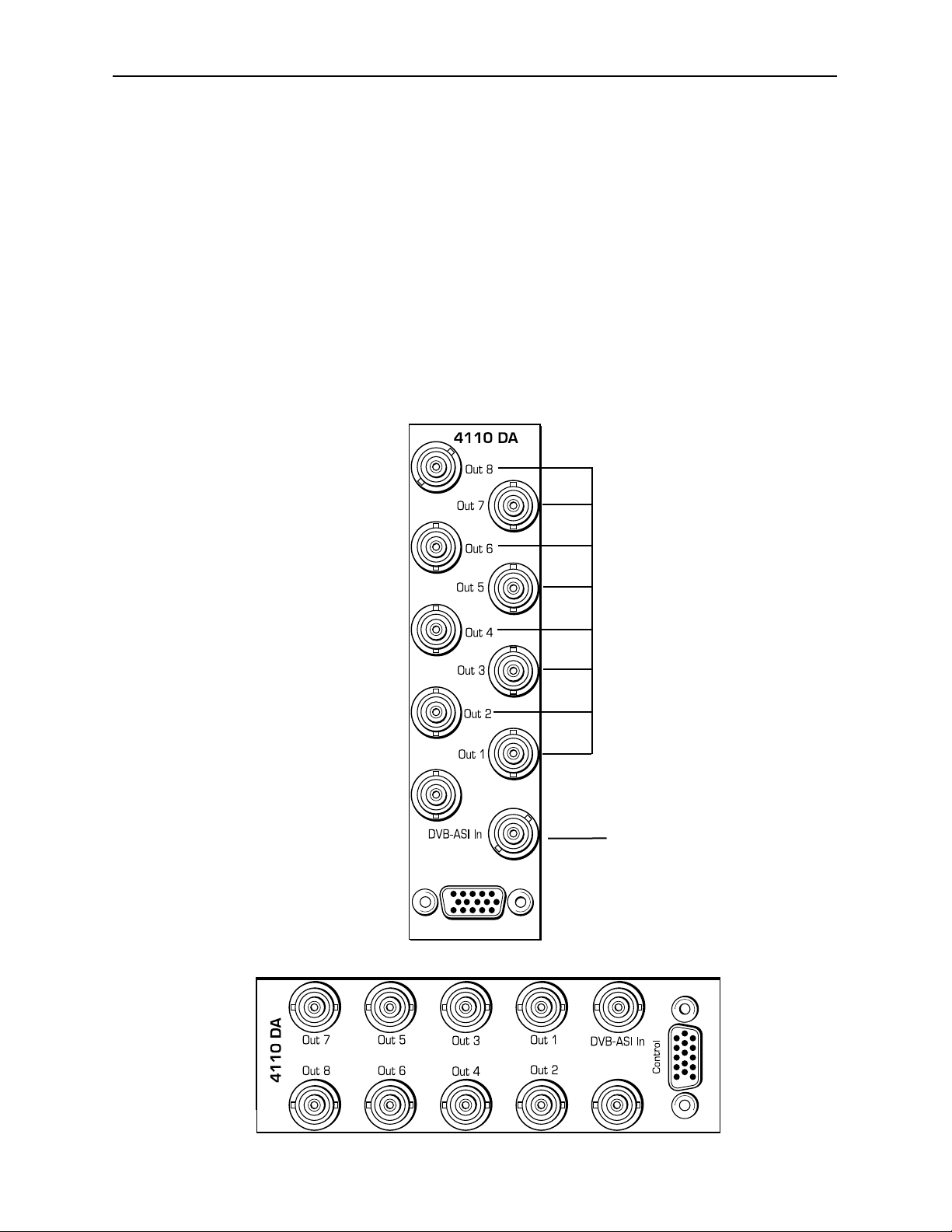
Refer to the 3 RU and 1 RU backplane diagrams of the module below for cabling
instructions. Note that unless stated otherwise, the 1 RU cabling explanations are
identical to those given in the 3 RU diagram.
Connect the DVB-ASI
signal to be distributed to
the DVB-ASI In BNC.
Connect DVB-ASI
output destinations to
the outputs at BNCs
Out 1 – Out 8.
3 RU Backplane
1 RU Backplane
Page 5

MODULE CONFIGURATION AND CONTROL
The configuration parameters for each Avenue module must be selected after installation.
This can be done remotely using one of the Avenue remote control options or locally using
the module front panel controls. Each module has a REMOTE/LOCAL switch on the
front edge of the circuit board which must first be set to the control mode you will be
using.
The configuration parameter choices for the module will differ between Remote and
Local modes. In Remote mode, the choices are made through software and allow more
selections. The 4110 Parameter Table below summarizes and compares the various con-
figuration parameters that can be set remotely or locally and the default/factory settings.
If you are not using an remote control option, the module parameters must be configured
from the front panel switches. Parameters that have no front panel control will be set to a
default value. The Local switches are illustrated in the Front Panel Controls and
Indicators section following the 4110 Parameter Table.
Avenue module parameters can be configured and controlled remotely from one or both of
the remote control options, the Avenue Touch Screen or the Avenue PC Application. Once
the module parameters have been set remotely, the information is stored on the module
CPU. This allows the module be moved to a different cell in the frame at your discretion
without losing the stored information. Remote configuration will override whatever the
switch settings are on the front edge of the module.
For setting the parameters remotely using the Avenue PC option, refer to the Avenue PC
Remote Configuration section of this document.
For setting the parameters remotely using the Avenue Touch Screen option, refer to the
Avenue Touch Screen Remote Configuration section of this data pack following
Avenue PC.
Model 4110 DVB-ASI DA
4110-5
4110 Parameter Table
CONTROL
Max Cable
LOCAL
REMOTE
DEFAULT VALUE
200-350 meters300 meters 300 meters
Page 6

Front Panel Controls and Indicators
Each front edge indicator and switch setting is explained in the diagram below:
Model 4110 DVB-ASI DA
Remote/Local switch:
Set to the mode you
will be using.
EQ OK green LED:
ON indicates signal is present
and equalized for all outputs.
OFF indicates the signal may not
be present or equalized.
Pwr green LED:
Indicates the presence (ON) or
absence (OFF) of power (+5V).
Run green LED:
OFF:
A power fault of halted CPU
ON:
A halted CPU
FAST BLINK:
CPU Run error
SLOW BLINK:
System OK. (If SPI control is
active from the main frame
System Control Module, all
Run indicators will be syn-
chronized.).
4110-6
Page 7

Avenue PC Remote Configuration
The Avenue PC remote control menu for this module is illustrated and explained below.
For more information on using Avenue PC, refer to the Avenue PC Control Application
Software data pack that came with the option.
4110 Avenue PC Menus
Set the following parameter from the Control menu:
• Max Cable – set the maximum cable equalization between 200 to 350 meters.
The following indicators are available from this menu:
• Cable Length – displays the amount of cable being equalized
• Equalizer – indicates input signal status of No Input or Input OK.
Model 4110 DVB-ASI DA
4110-7
Page 8

Avenue Touch Screen Remote Configuration
Avenue Touch Screen remote control menu for this module is illustrated and explained
below. For more information on using Avenue Touch Screens, refer to the Avenue Touch
Screen section of the Avenue System Overview.
4110 Avenue Touch Screen Menus
Set the following parameter from the Control menu:
• Max Cable – set the maximum cable equalization between 200 to 350 meters.
The following indicators are available from this menu:
• Cable Length – displays the amount of cable being equalized.
• Equalizer – indicates input signal status of No Input or Input OK.
Model 4110 DVB-ASI DA
4110-8
Page 9

TROUBLESHOOTING
As a troubleshooting aid, the signal equalization and presence, power and CPU status can
be easily monitored from the front panel of this module using the indicators explained in
the previous section.
If using the Remote mode, the following status items can be monitored using the Avenue
Touch Screen Control Panel or PC Application:
• Equalization (cable length)
• Power status
• Slot ID, Software Version and Board Revision
Refer to the overall troubleshooting tips given below for the module:
No status lights are lit on front panel:
• Check that frame power is present (green LED{s} on frame power supplies).
• Check that module is firmly seated in frame. Try removing it and plugging
it in again.
Can’t control module:
• Check status of CPU Run green LED. Should be blinking slowly and in
unison with other modules if System module is present. If not, try removing
it and plugging it in again.
• System module may not be working properly if installed.
No signal out of module:
• Check status of EQ OK green LED. Should be lit. If not, check the input
signal for presence and quality.
• Check cabling to input of module.
• Check remote cable equalization by switching the module to Local using
the front panel switch and see if the EQ OK LED comes on.
You may also refer to the technical support section of the Ensemble web site for the latest
information on your equipment at the URL below:
http://www
.ensembledesigns.com/support
SOFTWARE UPDATING
Software upgrades for each module can be downloaded remotely if the optional System
Control module is installed. These can be downloaded onto your PC and then Avenue PC
will distribute the update to the individual module. (Refer to the Avenue PC documentation for more information) Periodically updates will be posted on our web site. If you do
not have the required System Control Module and Avenue PC, modules can be sent back
to the factory for software upgrades.
Model 4110 DVB-ASI DA
4110-9
Page 10

Model 4110 DVB-ASI DA
4110-10
WARRANTYAND FACTORY SERVICE
Warranty
This Module is covered by a five year limited warranty, as stated in the main Preface of
this manual. If you require service (under warranty or not), please contact Ensemble
Designs and ask for customer service before you return the unit. This will allow the
service technician to provide any other suggestions for identifying the problem and
recommend possible solutions.
Factory Service
If you return equipment for repair, please get a Return Material Authorization Number
(RMA) from the factory first.
Ship the product and a written description of the problem to:
Ensemble Designs, Inc.
Attention: Customer Service RMA #####
870 Gold Flat Rd.
Nevada City, CA. 95959 USA
(530) 478-1830
Fax: (530) 478-1832
service@endes.com
http://www.ensembledesigns.com
Be sure to put your RMA number on the outside of the box.
Page 11

SPECIFICATIONS
4110 DVB-ASI DA
Input Signal Description:
Number: One
Signal Type: DVB-SSI, DVB-ASI @ 270 Mbps or SMPTE 310M
Impedance: 75 Ω
Return Loss: > 15dB DC to 270 MHz
Maximum Cable
Length: 300 meters
Output Signal Description
Number: Eight
Signal Type: Serial Digital (SMPTE 259M)
Impedance: 75 Ω
Return Loss: > 15dB Dc to 270 Mbps
General Specifications
Power Consumption: < 2.5 watts
Temperature Range: 0 to 40 degrees C ambient (all specs met)
Relative Humidity: 0 to 95% noncondensing
Altitude: 0 to 10,000 ft
Fusing: 1.5 Amp PTC resettable fuse
Due to ongoing product development, all specifications subject to change.
4110-11
Model 4110 DVB-ASI DA
 Loading...