

Page 1

EP-KL21
Motherboard of
Pentium II with MMX
User’s Manual
Order Number 41010005
December 1997
Page 2

EC-Conformity Declaration
(EC conformity marking)
FOR THE FOLLOWING EQUIPMENT:
Product Name : MOTHERBOARD
Model : EP-KL21
Manufacturer Address: 6FL., No. 19, Wu Chuan 6 Rd.
Wu-Ku Industrial Park, Taipei, Taiwan,
R.O.C.
IS HEREWITH CONFIRMED TO COMPLY WITH THE EQUIPMENTS
SET UP IN THE COUNCIL DIRECTIVE ON THE APPROXIMATION
OF THE LAW OF MEMER STATES RELATING TO
ELECTROMAGNETIC COMPATIBILITY (89/336/EEC) AND LOW
VOLTAGE DIRECTIVE 78/28/EEC. FOR THE EVALUATION
REGARDING THE ELECTROMAGNETIC COMPATIBILITY AND
SAFETY, THE FOLLOWING STANDARDS WERE APPLIED:
EN50081-1 (1992): GENERIC EMISSION STANDARDS
EN550022 (1994): EMISSION
EN60555-2 (1987): HARMONICS
EN60555-3 (1987): VOLTAGE FLUCTUATIONS
EN50082-1 (1992): GENERIC IMMUNITY STANDARD
IEC 801-2 (1984): ELECTROSTATIC DISCHARGE IMMUNITY
IEC 801-3 (1984): RADIATED IMMUNITY
IEC 801-4 (1988): ELECTRICAL FAST TRANSIENT
The manufacturer also declares the conformity of the above-mentioned
product, with the actual required safety standards in accordance with LVD
73/23 EEC.
Manufacturer/Importer
Date:
Signature: ___________________ Signature: .
Name : Jeff Chang Name : Kunnau Chen
Page 3

(Project Leader) (President)
Page 4

EP-KL21
Motherboard
for
Compatible PC
User Manual Rev 1.1
Related Motherboard: EP-KL21 P.C.B. Rev 1.X
Date: Dec. 1997
EP-KL21 User’s Manual
i
Page 5

TABLE OF CONTENTS
Chapter 1.............................................................................................1
1-1 About this Manual……......................................................................1
1-2 Item Checklist…………....................................................................2
1-3 Specifications………….....................................................................3
Chapter 2.............................................................................................6
2-1 Motherboard Description...................................................................6
2-2 Motherboard Layout……..................................................................7
2-3 System Memories……….............................................................…..8
2-4 Central Processing Unit (CPU)........................................................10
2-5 Expansion Cards & Slots.................................................................12
2-6 External Connectors…….................................................................13
2-7 Hardware Jumper/Switch Setup.......................................................25
EP-KL21 User’s Manual
ii
Page 6

FCC & DOC COMPLIANCE
Federal Communications Commission Statement
This device complies with FCC Rules Part 15. Operation is subject to
the following two conditions:
This device may not cause harmful interference, and
This device must accept any interference received, including
interference that may cause undesired operation.
This equipment has been tested and found to comply with the limits
for a Class B digital device, pursuant to Part 15 of the FCC Rules.
These limits are designed to provide reasonable protection against
harmful interference in a residential installation. This equipment
generates, uses and can radiate radio frequency energy and, if not
installed and used in accordance with manufacturer’s instructions,
may cause harmful interference to radio communications. However,
there is no guarantee that interference will not occur in a particular
installation. If this equipment does cause harmful interference to radio
or television reception, which can be determined by turning the
equipment off and on, the user is encouraged to try to correct the
interference by one or more of the following measures:
Re-orient or relocate the receiving antenna.
Increase the separation between the equipment and receiver.
Connect the equipment to an outlet on a circuit different from that to
which the receiver is connected.
Consult the dealer or an experienced radio/TV technician for help.
Warning: The use of shielded cables for connection of the monitor to
the graphics card is required to assure compliance with FCC
regulations. Changes or modifications to this unit not expressly
approved by the party responsible for compliance could void the
user’s authority to operate this equipment.
EP-KL21 User’s Manual
iii
Page 7

Federal Communications Commission (Continued...)
Canadian Department of Communications Statement
This digital apparatus does not exceed the Class B limits for radio
noise emissions from digital apparatus set out the Radio Interference
Regulations for the Canadian Department of Communications.
EP-KL21 User’s Manual
iv
Page 8

1
Chapter 1 INTRODUCTION
1-1 About this Manual
This manual is arranged to help you set up and run this Motherboard
of Pentium II with MMX as soon as possible.
The information is presented in the following two chapters:
Chapter 1 Introduction:
Presents what you should receive with your
motherboard, the features and specifications
of the product. This chapter enclosed with a
diagram showing the layout of the
motherboard.
Chapter 2 Installation:
Motherboard Installation includes detailed
information on how to install and configure
the motherboard.
EP-KL21 User’s Manual
Page 9

Chapter 1 INTRODUCTION
1-2 Item Checklist
This product comes with the following components:
Motherboard x 1
40-pin IDE Connector Flat Cable x 1
34-pin Floppy Disk Drive Flat Cable x 1
User’s Manual x 1
Bus Master IDE Drivers Diskette x 1 (Option)
Rear Panel Shielding (Option)
IrDA Module x 1 (Option)
LDCM Diskette x 1 (Option)
Note:
Option : Components will be included upon customer ordering
instructions per Proforma Invoice & additional external
procurement cost will be included.
EP-KL21 User’s Manual
2
Page 10

3
Chapter 1 INTRODUCTION
1-3 Specifications
Processor: Slot 1 support Intel Pentium II with MMX
Series CPU’s, CPU Clock Select support for
66 MHz CPU Bus speed configuration.
Chipset: Intel 82443LX System Controller
Intel 82371AB PCI/ISA IDE Accelerator
BIOS Award BIOS With Flash ROM, support PnP,
PCI 2.1, CD-ROM, ATAPI, LS-120, and any
IDE Device Bootable, Virus Protection, DMI
Ready
System Memory: 3 x 168-pin DIMM Slots Support Mixed
Memory Technologies: Extended Data Output
(EDO), Fast Page (FP) DRAM), Synchronous
DRAM (SDRAM)
Multi-I/O Onboard: 1 x FDD Port support up to 2.88MB
1 x Parallel Port (LPT) support ECP/EPP
2 x High Speed Serial (16C550 UART) Ports
2 x Universal Serial Bus (USB) Ports
1 x PS/2 Keyboard Port
1 x PS/2 Mouse Port
2 x IrDA Infrared Interfaces
EP-KL21 User’s Manual
Page 11

Chapter 1 INTRODUCTION
PCI Bus Master IDE: PCI Enhanced IDE Interface with 4 IDE
Devices
Support HDD Auto-Detect
Support up to PIO Mode 4, DMA Mode 2
Support Ultra DMA/33 mode
Fully compatible with PCI Local Bus
Specifications V2.1
ATX Stack Connector: 2 x USB Ports, 1 x PS/2 Keyboard Port, 1 x
PS/2 Mouse Port, 1 x Parallel Port, 2 x Com
Port
Expansion Slots: 3 x 16-bit ISA Slots with 100% ISA
Compatible Functions
4 x 32-bit PCI Slots supporting PCI BUS
Master Slots Conform with PCI
Specifications Version 2.1
1 x AGP Slot supported.
Options: 2 x Infrared (IrDA) Wireless Interface Kit
(Front & Rear)
Universal Serial Bus (USB) Connector Kit
LM78 Hardware Monitor Circuit Design and
LM75 CPU Temperature reading, LDCM
for system Voltage, System Temperature,
Fan Speed detect.
EP-KL21 User’s Manual
4
Page 12

5
Chapter 1 INTRODUCTION
Extended Features: Advanced Configuration and Power Interface
(ACPI) ready
CPU Temperature detect
Support System Power Monitor
Support Win95 Soft Power Off (For ATX
Power only)
Support SM-Bus
Dimension: 305 mm x 195 mm
Form Factor: ATX Form Factor
EP-KL21 User’s Manual
Page 13

Chapter 2 INSTALLATION
2-1 Motherboard Description
The motherboard is designed with the Intel 82440LX PCI chipset
which is developed by Intel Corporation to fully support the
Pentium II Processor PCI/ISA system. The Intel 82440LX PCI chipset
provides increased integration and improved performance designs.
The chipset provides an integrated IDE controller with two high
performance IDE interfaces for up to four IDE devices (hard devices,
CD-ROM device, etc). The Super I/O controller provides the standard
PC I/O function: floppy interface, two 16Byte FIFO serial ports and
EPP/ECP capable parallel port.
Care must be taken when inserting memory modules, inserting CPU
or even plugging PCI card into associated slots to avoid damaging any
circuits or sockets on board. A cooling fan is strongly recommended.
The motherboard supports minimum of 8MB of system memory and a
maximum of 512MB SDRAM, 1GB EDO RAM.
The motherboard supports standard Fast Page (FP), EDO (Extended
Data Output), or SDRAM (Synchronous DRAM). The motherboard
provides three 168-pin DIMM. The socket supports 1Mx32 (32MB)
single-sided or double-sided memory modules. The memory timing
requires 70ns Fast Page devices or 60ns EDO RAM. Memory parity
generation and checking is not supported. (DRAM Modules may be
parity (x36) or non-parity (x32).
The board also supports onboard two PCI IDE connectors, and detects
the IDE hard disk type by the BIOS utility which is automatic. The
system also supports Award Plug & Play BIOS for the ISA and PCI
cards.
EP-KL21 User’s Manual
6
Page 14
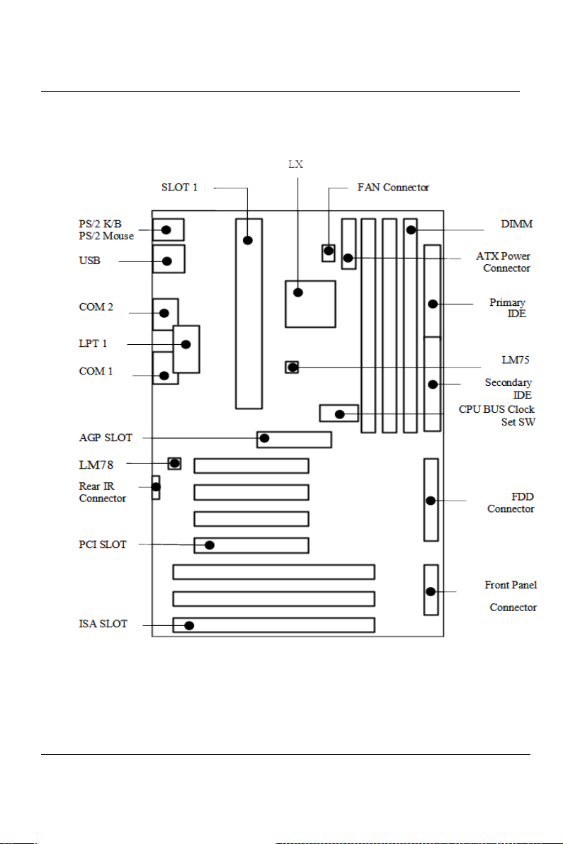
7
Chapter 2 INSTALLATION
2-2 Motherboard Layout
EP-KL21 User’s Manual
Page 15

Chapter 2 INSTALLATION
2-3 System Memories
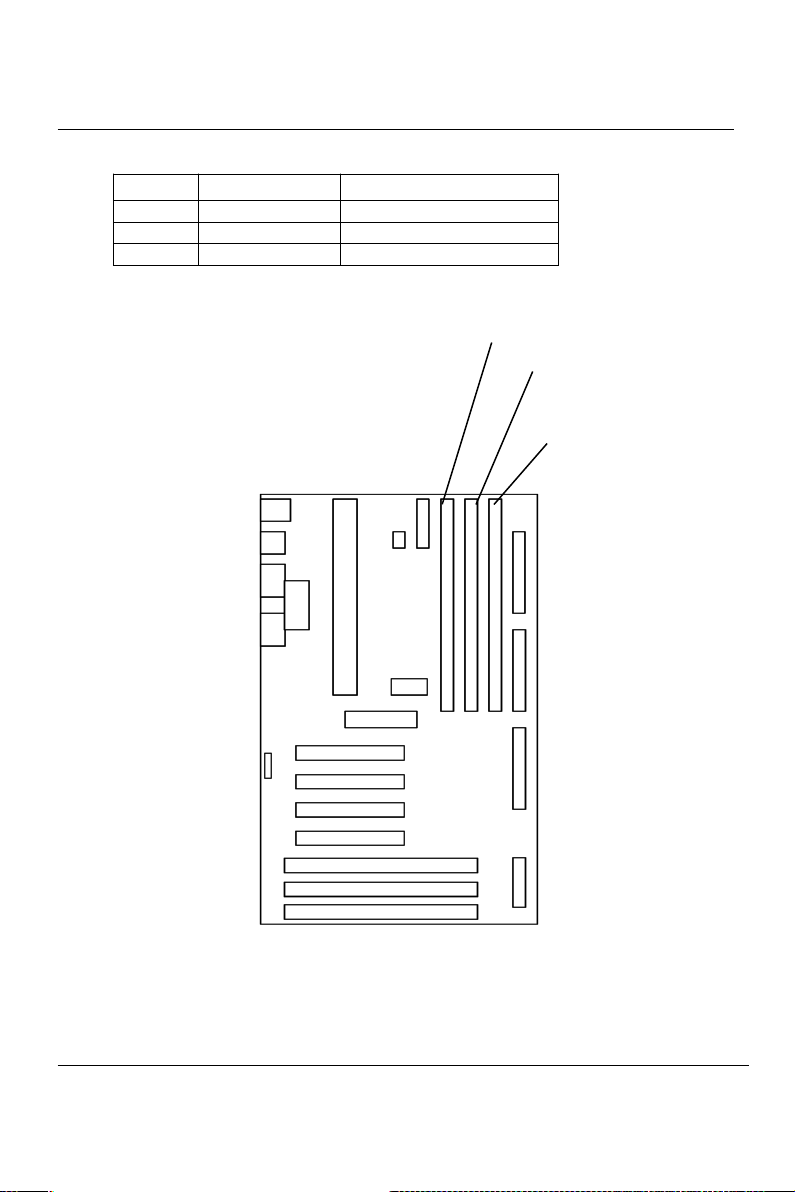
This motherboard supports three 168-pin DIMM. The SDRAM can be
either 60ns.
Install memory in any or all of the banks in any combination as the
following page:
EP-KL21 User’s Manual
8
Page 16
9
Chapter 2 INSTALLATION
Item Bank Memory Module
1 DIMM 1 8~256MB
2 DIMM 1, 2 8~256MB
3 DIMM 1, 2, 3 8~256MB
EP-KL21 User’s Manual
DIMM3
DIMM 2
DIMM 1
Page 17
Chapter 2 INSTALLATION
2-4 Central Processing Unit (CPU)
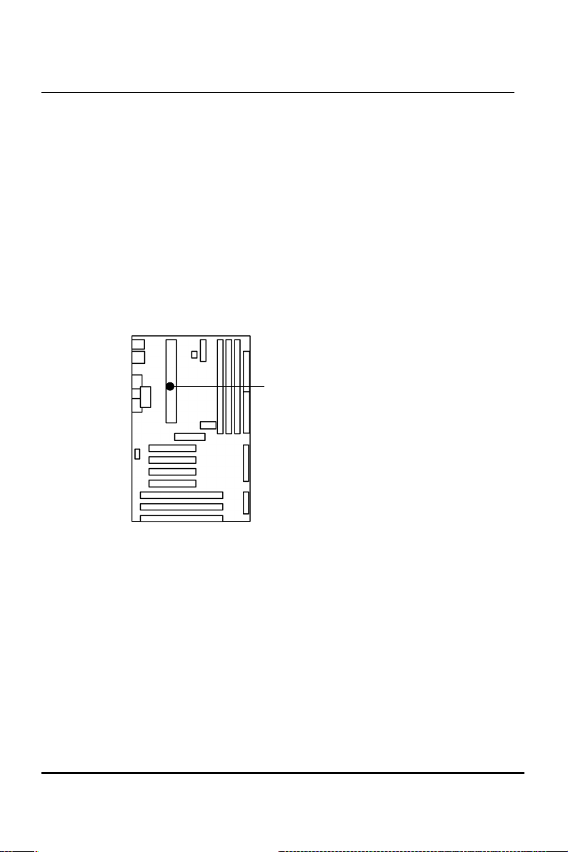
The motherboard provides a SLOT 1 for Pentium II CPU. The CPU
should have a fan attached to it to prevent overheating. If your CPU
did not come with a fan, then purchase a fan before you turn on your
system.
NOTE: Without a fan, the CPU can overheat and cause damage
to both the CPU and the motherboard.
EP-KL21 User’s Manual
SLOT 1
10
Page 18
11
Chapter 2 INSTALLATION
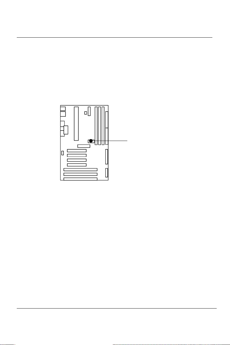
To install a CPU, locate the SLOT 1. Insert the CPU with the correct
orientation. you should have a CPU fan that will cover the face of the
CPU.
EP-KL21 User’s Manual
SW1 : (Use dip sw. or pin header)
CPU Bus Clock Select
Page 19
Chapter 2 INSTALLATION
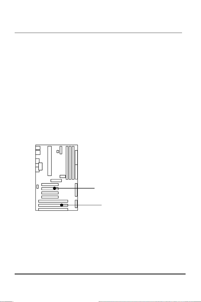
2-5 Expansion Cards & Slots
Assigning DMA Channels for ISA Cards:
Some ISA cards, both Legacy and PnP may also need to use a DMA
(Direct Memory Access) channel. DMA assignments for this
motherboard are handled the same way as the IRQ assignment process
. You can select a DMA channel in the PCI and PnP configuration
section of the BIOS Setup utility.
NOTE: Choose “Legacy ISA” for those IRQ’s and DMA’s you
wish to reserve for Legacy (Non-PnP) ISA expansion
cards in “IRQ xx Used by ISA” and “DMA x Used By
ISA” of the PnP and PCI Setup in the BIOS Software
section, otherwise conflicts may occur.
EP-KL21 User’s Manual
12
4 x PCI SLOTS
3 x ISA SLOTS
Page 20
13
Chapter 2 INSTALLATION
2-6 External Connectors
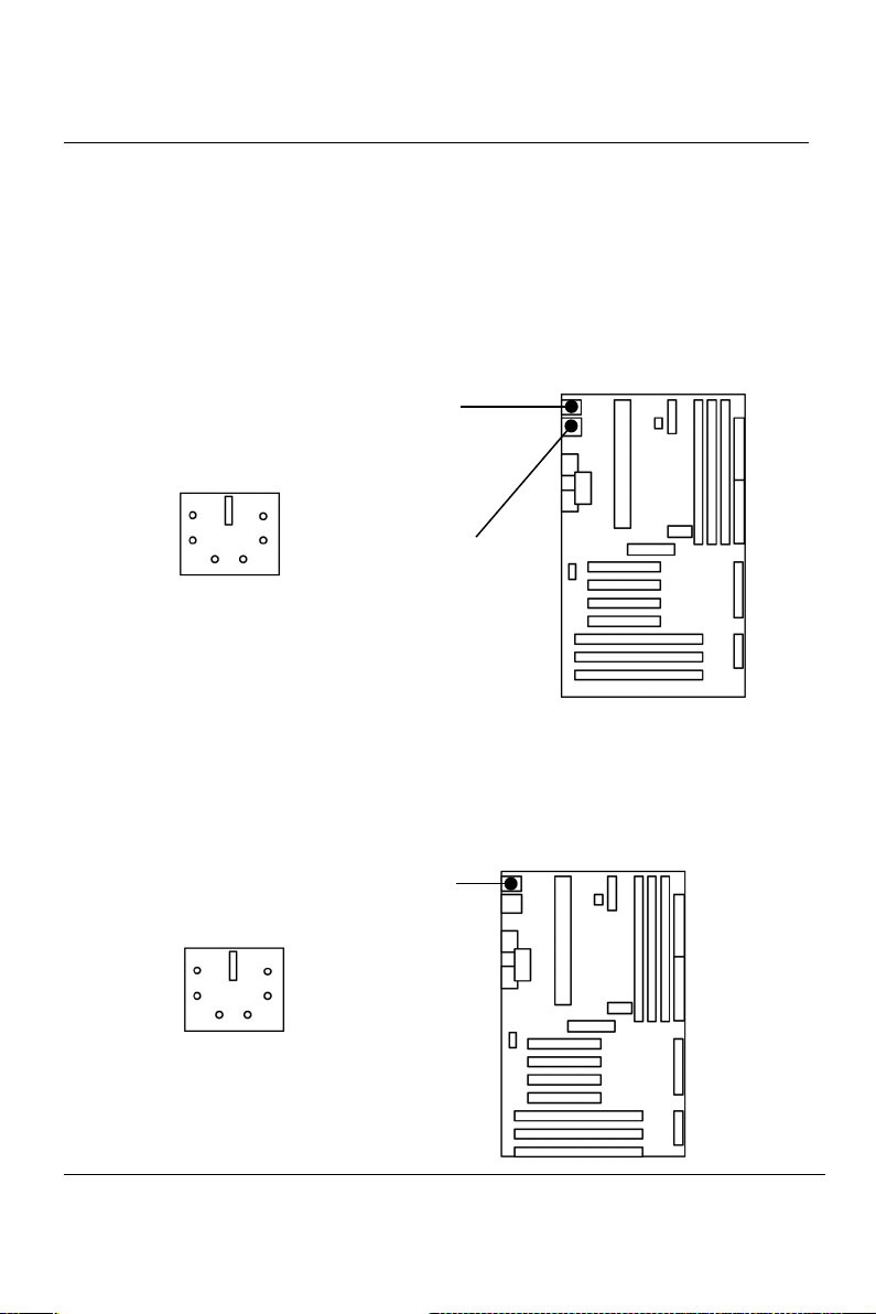
1. PS/2 Keyboard Connector and USB Port (J12, 6-pin Female
and J8, USB Connector)
This connection is for a standard keyboard using PS/2 plug (mini
DIN). This connector will not allow standard AT size (large DIN)
keyboard plugs. You may use a DIN to mini DIN adapter on
standard AT keyboard.
2. PS/2 Mouse Connector (J7, 6-pin Female)
The system will direct IRQ12 to the PS/2 mouse if one is
detected. If not detected, expansion cards can use IRQ12.
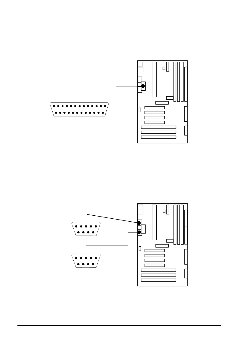
3. Parallel Port (J9, 25-pin Female)
EP-KL21 User’s Manual
J12: PS/2 Keyboard
Connector
J8 : USB Port
(Support Standard
USB Spec.)
J7: PS/2 Mouse Connector
Page 21
Chapter 2 INSTALLATION
You can enable the parallel port (LPT1) and choose the IRQ
through BIOS Setup on “Onboard Parallel Port”.
4. Serial Ports (J10: COM1, J11: COM2, 9-pin Male).
The two serial (COM1 & COM2) ports can be used for pointing
devices or other serial devices. See “Onboard Serial Port” in
Chipset Features Setup of the BIOS Software.
EP-KL21 User’s Manual
J9: Parallel Port
1
14
J11: Com2
J10: Com1
Page 22
15
Chapter 2 INSTALLATION
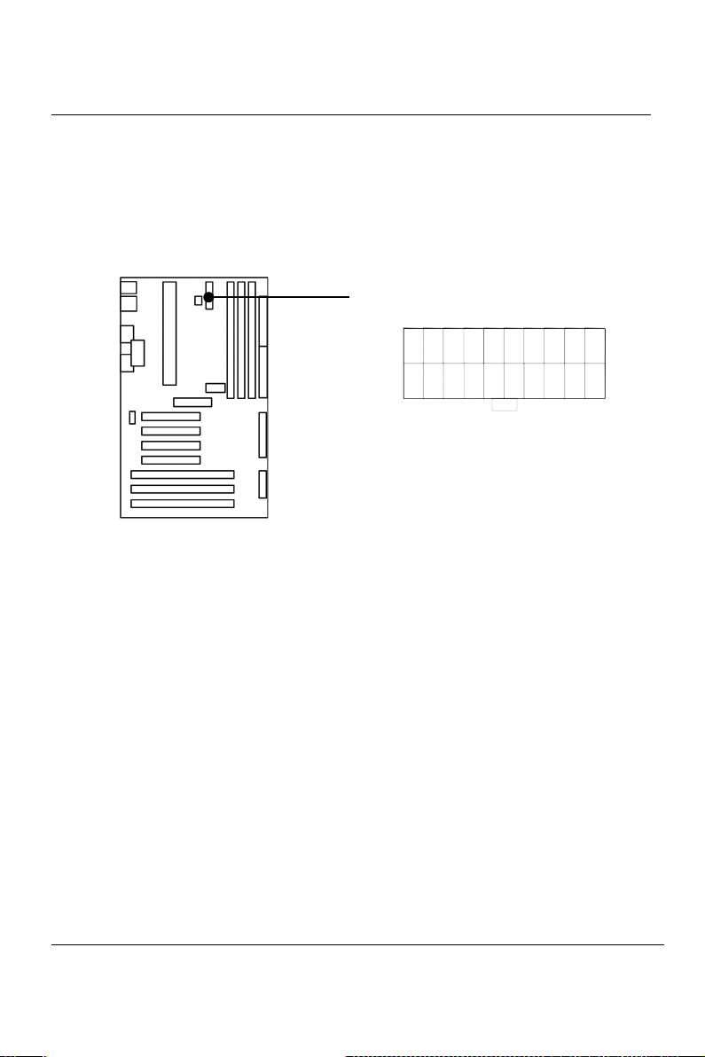
5. ATX Power Connector (PS1, 20-pin block)
This connector connects to an ATX power supply. The plug from
the power supply will only insert in one orientation because of
the different hole sizes. Find the proper orientation and pushed
down firmly making sure that it is locked in place.
NOTE:
To prevent electrical spikes, make sure that the power
supply is not connected to an outlet when making or removing
connections. Power supplies contain power reserves which can
damage electrical components.
EP-KL21 User’s Manual
PS1: ATX Power Connector
Page 23

Chapter 2 INSTALLATION
6. Floppy Drive Connector (J2, 34-pin block)
This connector supports the provided floppy disk drive ribbon
cable. After connecting the single end to the board, connect the
plugs on the other end to one or two floppy drives.
EP-KL21 User’s Manual
J2: FDD Connector
16
Page 24
17
Chapter 2 INSTALLATION
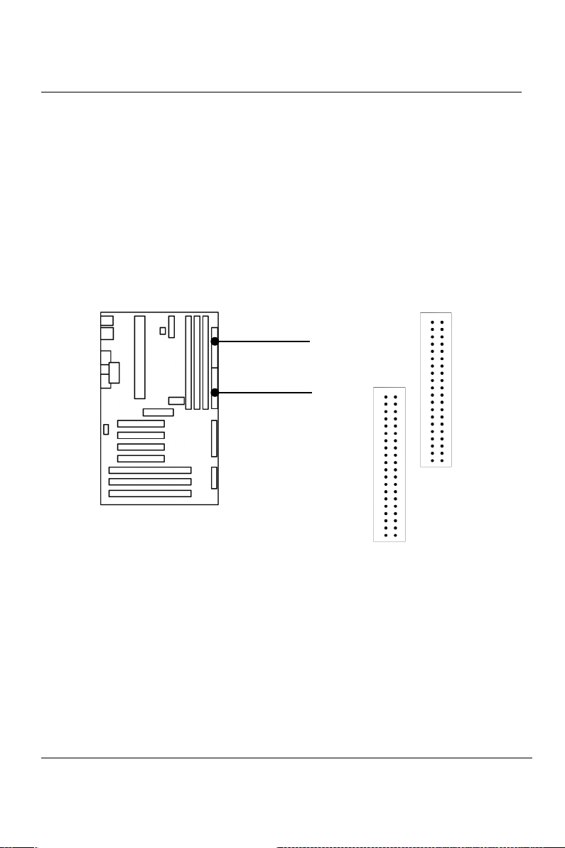
7. Primary/Secondary IDE connectors (J3 & J4: Two 40-pin
Blocks)
These connectors support the provided IDE hard disk ribbon
cable. After connecting the single end to the board, connect the
two plugs at the other end to your hard disk(s). If you install two
hard disks, you must configure the second drive to Slave mode by
setting its jumper accordingly. Please refer to the documentation
of your hard disk for the jumper settings.
EP-KL21 User’s Manual
J4: Primary
HDD
J3: Secondary
HDD
Page 25
Chapter 2 INSTALLATION
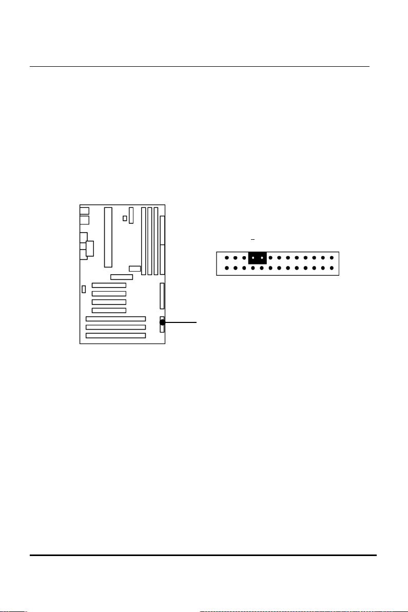
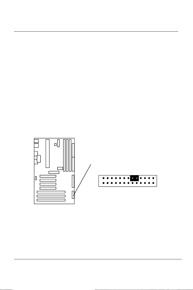
8. a. IDE Activity LED (J1, Pin 17,19)
This connector connects to the IDE (hard disk) activity
indicator light on the system cabinet.
EP-KL21 User’s Manual
J1, Pin 17,19 : IDE Activity LED
+
1
18
Page 26
19
Chapter 2 INSTALLATION
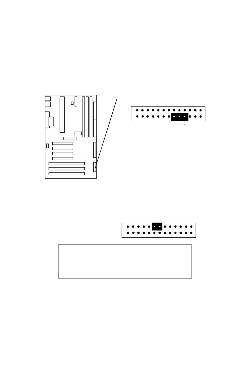
b. System Power LED (J1, Pin 8,10,12)
This 3-pin connector lights the system power LED when the
motherboard has power.
c. Turbo LED (J1, Pin 13,15)
EP-KL21 User’s Manual
- +
+
J1, Pin 8,10,12:System Power LED
For 3-pin Power LED Connector
Pin 8 : GND
10 : NC
12 : VCC
If the cabinet provide the turbo LED cable,
connect the cable to this two pin connector to
turn on the LED on the front panel.
1
Page 27
Chapter 2 INSTALLATION
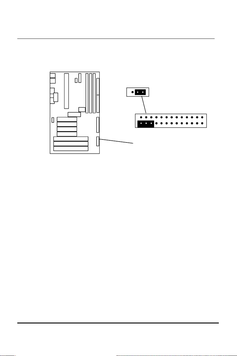
d. CMOS Clear (J1, Pin 22,24,26)
EP-KL21 User’s Manual
J1, Pin 22,24,26:
Clear CMOS
Clear : Pin 22,24
Normal : Pin 24,26 (Default)
ClearNormal
1
1 +
20
Page 28
21
Chapter 2 INSTALLATION
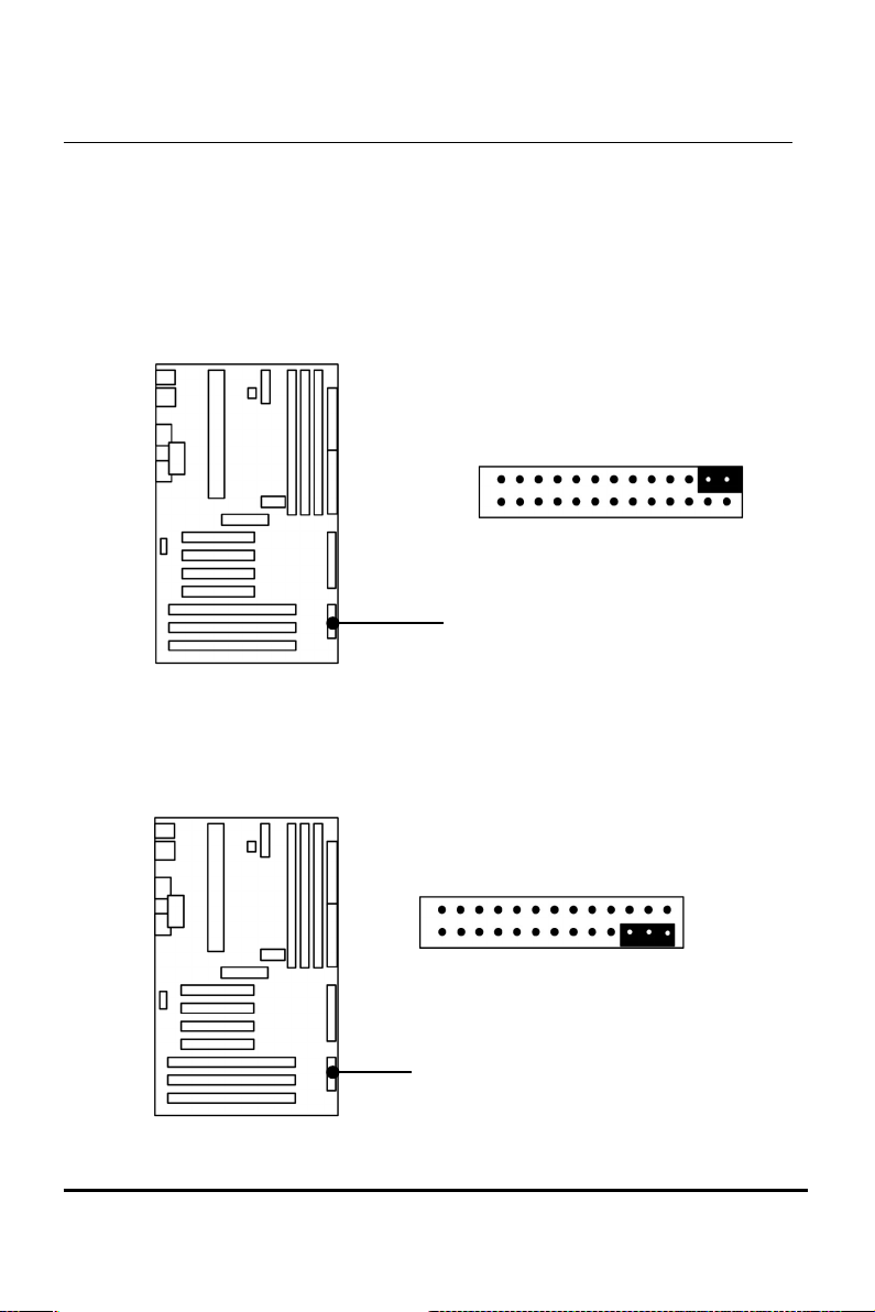
e. ATX Power Switch Lead ( J1, Pin 9,11)
The system power is controlled by a push-switch, connected
to this lead. Pushing the button once will turn on the power
and pushing again will turn off the power. The system power
LED shows that status of the system’s power. This
connection does not have a function when a standard power
supply is used.
NOTE: If the power to the ATX power supply is interrupted
while the motherboard is on, standby power will
remember that the motherboard should be on and boot
the computer when power is reapplied to the ATX
power supply.
EP-KL21 User’s Manual
J1, Pin 9,11:
ATX Power Switch Lead
1
Page 29
Chapter 2 INSTALLATION
f. Reset Switch Lead (J1, Pin 1,3)
This 2-pin connector connects to the case-mounted reset
switch for rebooting your computer without having to turn
off your power switch. This is a preferred method of
rebooting in order to prolong the life of the system’s power
supply.
g. Keyboard Lock Switch Lead
(J1, Pin 2,4,6)
This 3-pin connector connects to the case-mounted keyboard
lock switch for locking the keyboard.
EP-KL21 User’s Manual
J1, Pin 2,4,6 : KEYLOCK
J1, Pin 1,3: Reset Switch Lead
1
22
Keylock
Page 30
23
Chapter 2 INSTALLATION
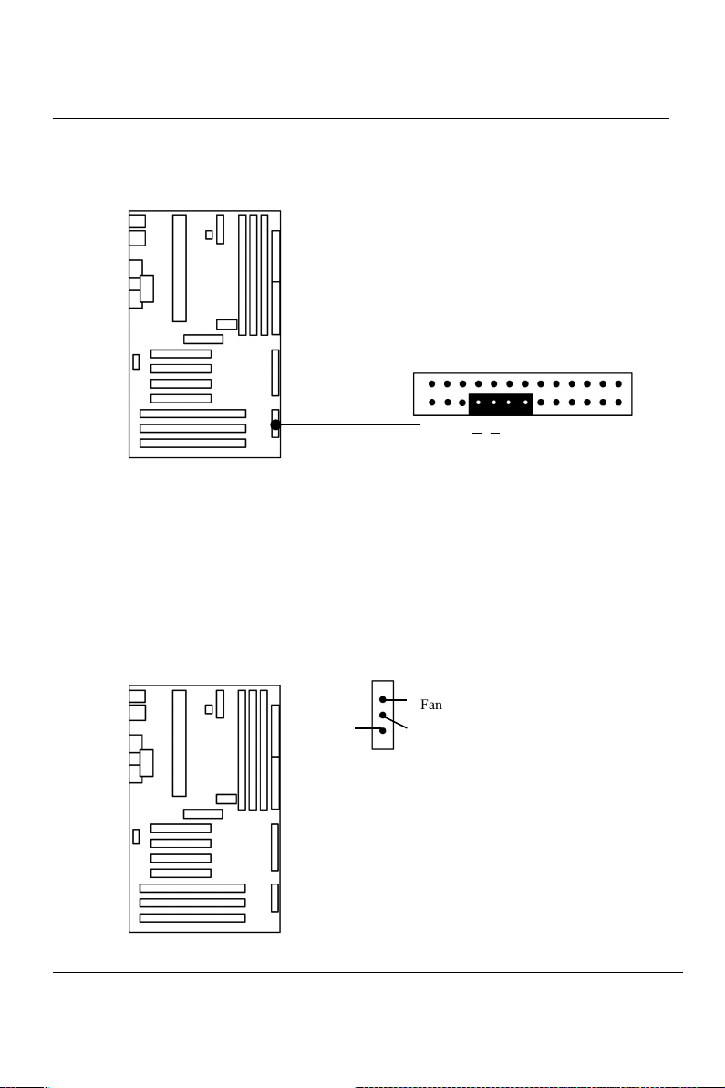
9. Speaker Connector (J1, Pin 14,16,18,20)
This 4-pin connector connects to the case-mounted speaker.
10. CPU Cooling Fan Connector (JP8 support fan detect)
This connector support a CPU cooling fan of 500 mAMP
(6WATT, +12V) or less. Orient the fan so that the heat sink fins
allow airflow to go across the onboard heat sink(s). Depending
on the fan manufacturer, the wiring and plug may be different.
The red wire should be positive, while the black should be
ground. Connect the fan’s plug to the board taking into
consideration the polarity of the connector.
EP-KL21 User’s Manual
JP8, FAN Connector
J1, Pin 14,16,18,20:
Speaker Connector
+ +
1
1
Fan Detect
GND
Page 31
Chapter 2 INSTALLATION
NOTE: The CPU and/or motherboard will overheat if there is
no airflow across the CPU and onboard heat sinks.
Damage may occur to the motherboard and/or the CPU
fan if these pins are incorrectly used. These are not
jumpers, do not place jumper caps over these pins.
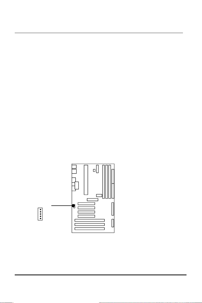
11. IrDA Compliant Infrared Module Connector (J13, Rear IrDA)
These connectors support the optional wireless transmitting and
receiving infrared module. This module mounts to a small
opening on system cases that support this feature. You must also
configure UART 2. Use Infrared in Chipset Features Setup to
select whether UART 2 is directed for use with COM2 or IrDA.
When IrDA is selected in BIOS, COM2 will be disabled. Use the
five pins or six pins as shown and connect a ribbon cable from
the module to the motherboard to the pin definitions.
EP-KL21 User’s Manual
1
Pin 1 : VCC
2 : IRRX
3 : NC
4 : GND
5 : IRTX
J13: IrDA Rear
24
Page 32
25
Chapter 2 INSTALLATION
2-7 Hardware Jumper/Switch Setup
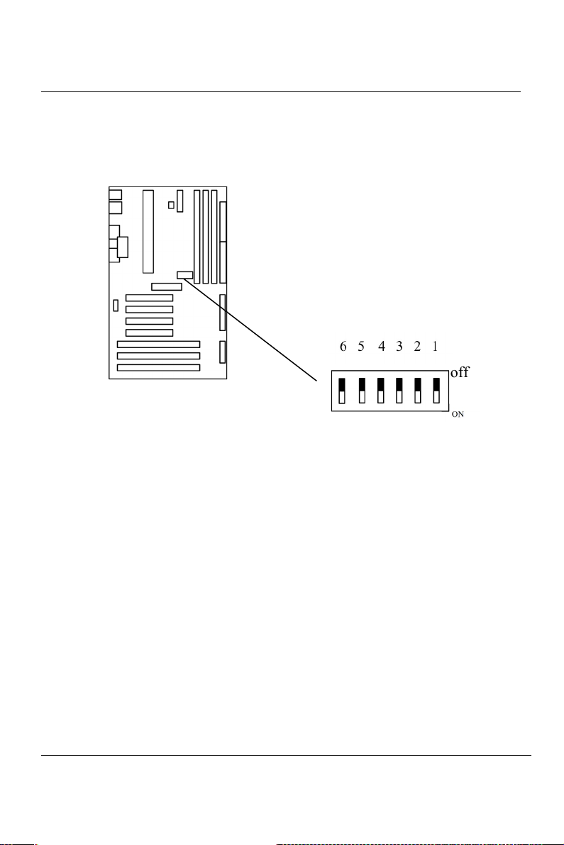
12. External HCLK Frequency Setup (Fixed to 66 MHz)
EP-KL21 User’s Manual
Default setting :
SW1: 1~4 Fixed to off position
off
SW1 : 5~6 Fixed to off
Page 33
Chapter 2 INSTALLATION
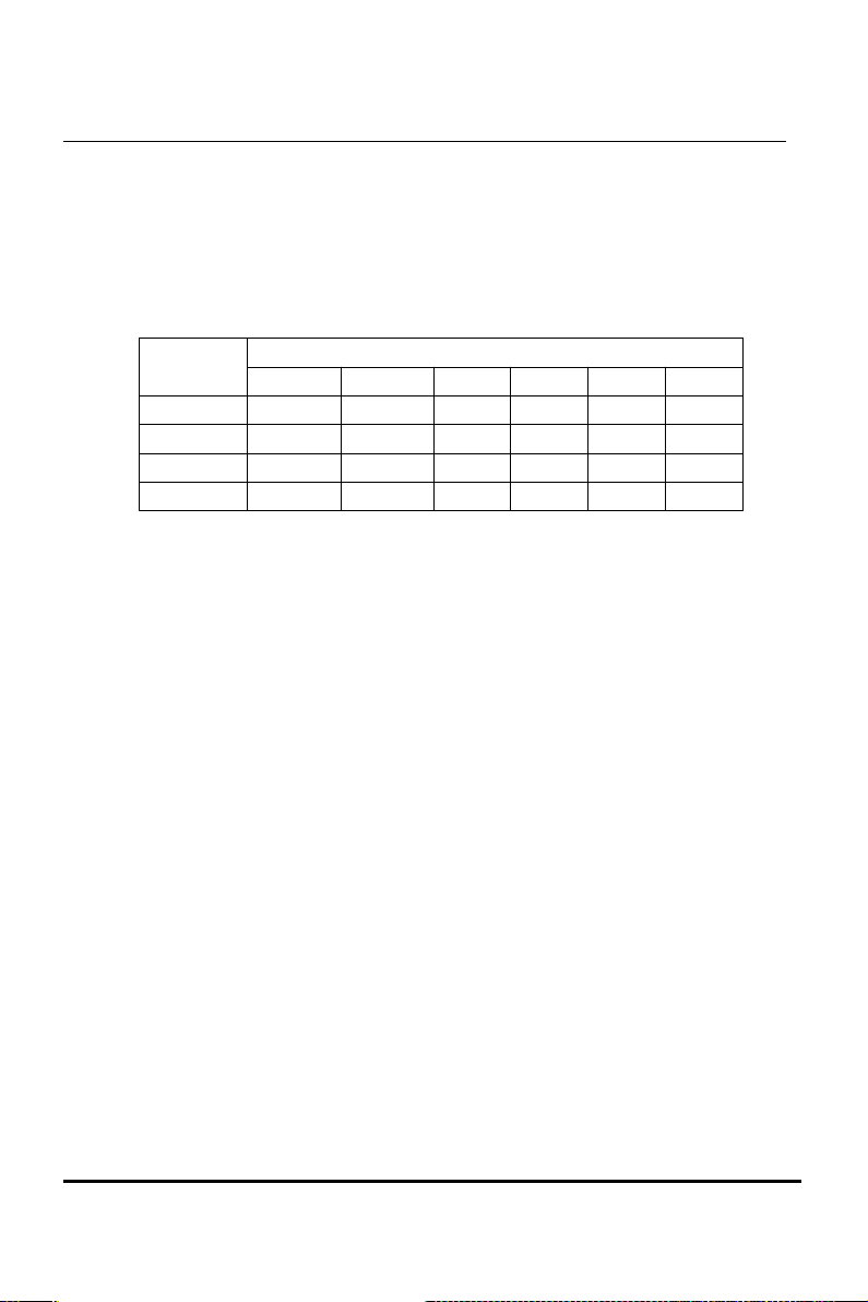
13. Frequency Ratio Select Table (SW1)
CPU SPEED
SW 1
1 2 3 4 5 6
233 ON OFF OFF ON OFF OFF
266 OFF ON ON ON OFF OFF
300 OFF ON OFF ON OFF OFF
333 OFF OFF ON ON OFF OFF
( NOTE : The CPU Speed is in MHz )
EP-KL21 User’s Manual
26
Page 34

100
POST-CONSUMER
RECYCLED PAPER
EP-KL21
User’s Manual
 Loading...