

Page 1

EP-KE21
Motherboard of
Pentium II with MMX
User’s Manual
Order Number 41010017
User Manual Rev 1.0
Related Motherboard: P.C.B. Rev 1.0
Date: MAY 1998
Page 2

TABLE OF CONTENTS
Chapter 1 INSDUCTION ................................................................1
1-1 About this Manual……......................................................................1
1-2 Item Checklist…………....................................................................2
1-3 Specifications………….....................................................................3
Chapter 2 INSTALLATION...........................................................6
2-1 Motherboard Description...................................................................6
2-2 Motherboard Layout……..................................................................7
2-3 System Memories……….............................................................…..7
2-4 Central Processing Unit (CPU)........................................................10
2-5 Expansion Cards & Slots.................................................................12
2-6 External Connectors…….................................................................13
2-7 Hardware Jumper Setup...................................................................25
Chapter 3 SPECIAL FEATURE..................................................28
3-1 Security Keyboard and Mouse Power On........................................28
3-2 Modem Ring / LAN Power On ……...............................................28
3-3 Hardware Monitorning ……............................................................28
Chapter 4 APPENDIX ..................................................................29
A What is AGP (Accelerated Graphics Port) ? .................................29
B ISO 9002 QA Certificate ...............................................................30
EP-KL11/KE11 User's Manual
i
Page 3

1-1 About this Manual
This manual is arranged to help you set up and run this Motherboard
of Pentium II with MMX as soon as possible.
The information is presented in the following two chapters:
Chapter 1 INTRODUCTION
Presents what you should receive with your
motherboard, the features and specifications
of the product. This chapter enclosed with a
diagram showing the layout of the
motherboard.
Chapter 2 INSTALLATION
Motherboard Installation includes detailed
information on how to install and configure
the motherboard.
Chapter 3 SPECIAL FEATURE
Describes this motherboard special feature of
"Security Keyboard and Mouse Power On",
"Modem Ring/LAN Wake-Up", "Hardware
Monitoring".
Chapter 4 APPENDIX
This appendix describes what the AGP is and
presents the ISO9002 certificate.
EP-KE21 User's Manual
i
Page 4

Chapter 1 INTRODUCTION
1-2 Item Checklist
This product comes with the following components:
Motherboard x 1
40-pin IDE Connector Flat Cable x 1
34-pin Floppy Disk Drive Flat Cable x 1
User’s Manual x 1
CPU Retention Mechanism Kit x 1
Audio Software Drivers Diskette x 1
Winbond W83781 Hardware Monitoring
Detection Drivers Diskette x 2
Bus Master IDE/Ultra DMA-33 Drivers Diskette x 1 (Option)
IrDA Module x 1 (Option)
LDCM Diskette x 1 (Option)
Option : Components will be included upon customer ordering
instructions per Proforma Invoice & additional
external procurement cost will be included.
EP-KE21 User's Manual
1
Page 5

Chapter 1 INTRODUCTION
1-3 Specifications
Processor: Slot 1 support Intel Pentium II with MMX
Series CPU’s, CPU Clock Select support for
66, 75, 83 MHz CPU Bus speed
configuration.
Chipset: Intel 82443EX System Controller
Intel 82371EB PCI/ISA IDE Accelerator
3D Audio High Performance Chips
Ultra I/O Chip with security Keyboard/Mouse
Power On, Modem/LAN Wake-Up
BIOS Award BIOS With Flash ROM, support PnP,
PCI 2.1, CD-ROM, ATAPI, LS-120, and any
IDE Device Bootable, Virus Protection, DMI
Ready
System Memory: 2 x DIMMs Slots Support Mixed Memory
Technologies: Extended Data Output (EDO),
Synchronous DRAM (SDRAM)
Multi-I/O Onboard: 1 x FDD Port support up to 2.88MB
1 x Parallel Port (LPT) support ECP/EPP
2 x High Speed Serial (16C550 UART) Ports
2 x Universal Serial Bus (USB) Ports
1 x PS/2 Keyboard Port
1 x PS/2 Mouse Port
2 x IrDA Infrared Interfaces
EP-KE21 User's Manual
2
Page 6

Chapter 1 INTRODUCTION
PCI Bus Master IDE: PCI Enhanced IDE Interface with 4 IDE
Devices
Support HDD Auto-Detect
Support up to PIO Mode 4, DMA Mode 2
Support Ultra DMA/33 mode
Fully compatible with PCI Local Bus
Specifications V2.1
I/O Connector: 2 x USB Ports, 1 x PS/2 Keyboard Port, 1 x
PS/2 Mouse Port, 1 x Parallel Port, 2 x Com
Port, 1 x MIDI/Game Port, 1 x Audio Line in
Port, 1 x Audio Line Out Port, 1 x Audio
Mic. In Port, 1 x CD-IN port
Expansion Slots: 1 x 16-bit ISA Slots with 100% ISA
Compatible Functions
3 x 32-bit PCI Slots supporting PCI BUS
Master Slots Conform with PCI
Specifications Version 2.1
1 x AGP Slot supported.
Options: 2 x Infrared (IrDA) Wireless Interface Kit
(Front & Rear)
Universal Serial Bus (USB) Connector Kit
W83781 Hardware Monitor Circuit Design
and CPU Temperature reading, LDCM for
system Voltage, System Temperature, Fan
Speed detected.
EP-KE21 User's Manual
3
Page 7

Extended Features: Advanced Configuration and Power Interface
(ACPI) ready
CPU Temperature detect
Support System Power Monitor
Support Win95 Soft Power Off
Surround 3D Audio with LINE-IN, LINEOUT, MIC-IN and MIDI/GAME port
Compliant with PC97
Support SM-Bus
Dimension: 244 mm x 200 mm
Form Factor: Micro ATX Form Factor
Page 8

Chapter 2 INSTALLATION
2-1 Motherboard Description
The motherboard is designed with the Intel 82440EX PCI chipset
which is developed by Intel Corporation to fully support the
Pentium II Processor PCI/ISA system. The Intel 82440EX PCI chipset
provides increased integration and improved performance designs.
The chipset provides an integrated IDE controller with two high
performance IDE interfaces for up to four IDE devices (hard devices,
CD-ROM device, etc). The Super I/O controller provides the standard
PC I/O function: floppy interface, two 16Byte FIFO serial ports and
EPP/ECP capable parallel port.
Care must be taken when inserting memory modules, inserting CPU
or even plugging PCI card into associated slots to avoid damaging any
circuits or sockets on board. A cooling fan is strongly recommended.
The motherboard supports minimum of 8MB of system memory and a
maximum of 256 MB SDRAM.
The motherboard supports EDO (Extended Data Output), or SDRAM
(Synchronous DRAM). The motherboard provides two 168-pin
DIMM sockets.
The board also supports two onboard PCI IDE connectors, and
automatically detects the IDE hard disk type through the BIOS utility.
The system also supports Award Plug & Play BIOS for the ISA and
PCI cards.
Page 9
Chapter 2 INSTALLATION
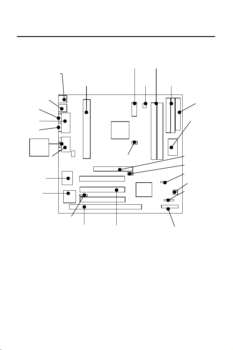
2-2 Motherboard Layout
PS/2 Mouse
PS/2 Keyboard
USB Port
COM 1
LPT
COM 2
Line-In
Line-out
Mic.-In
MIDI/Game
Port
Audio Chip
I/O Chip
Rear IR
Conn.
CD-In
SLOT 1
ATX PWR Conn.
440EX
HCLK SELECTOR
PCI SlotISA Slot
FAN
371EB
DIMM Socket
IDE Conn.
FDD
BIOS
AGP Slot
Ratio Selector
CMOS Clear
FAN 2
Front IR
Conn.
Front Panel Conn.
Page 10

Chapter 2 INSTALLATION
2-3 System Memories
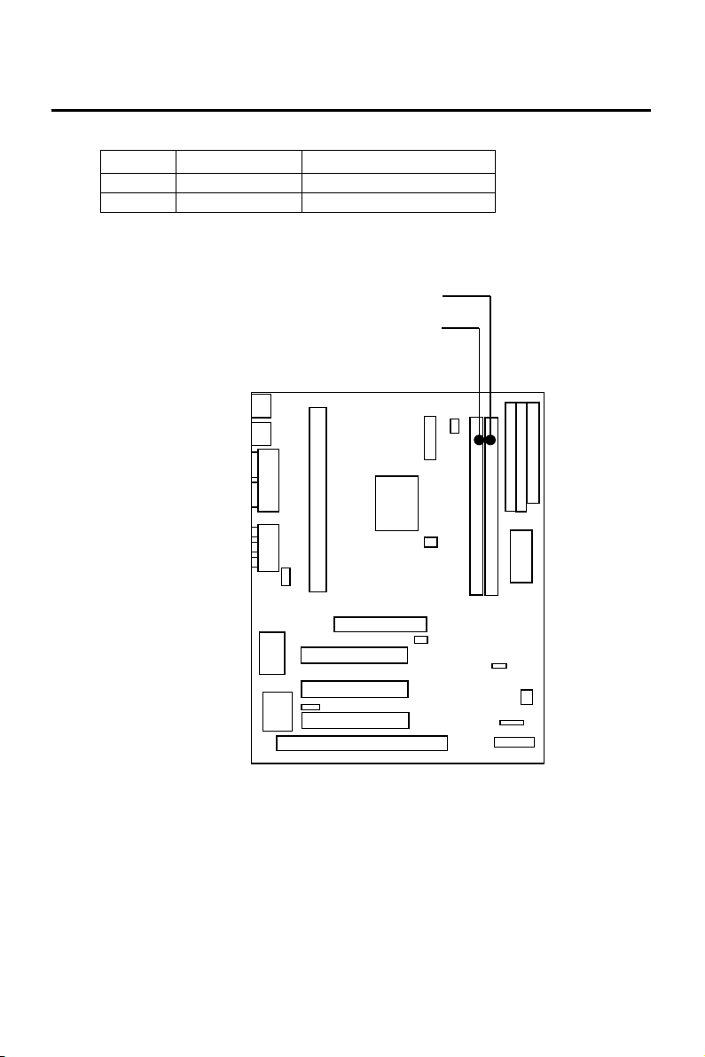
This motherboard only supports Dual Inline Memory Modules
(DIMM’S), The Dual Inline Memory Module (DIMM) must be 3.3
Volt Unbuffered Synchronous DRAM (SDRAM) of either 8, 16,
32, 64, or 128MB to form a memory size between 8MB to 256MB.
Note : Install memory in any or all of the banks in any combination as
the following page :
Page 11
Chapter 2 INSTALLATION
Item Bank Memory Module
1 DIMM 1 8~128MB
2 DIMM 1, 2 8~128MB
DIMM 2
DIMM 1
Page 12
Chapter 2 INSTALLATION
2-4 Central Processing Unit (CPU)
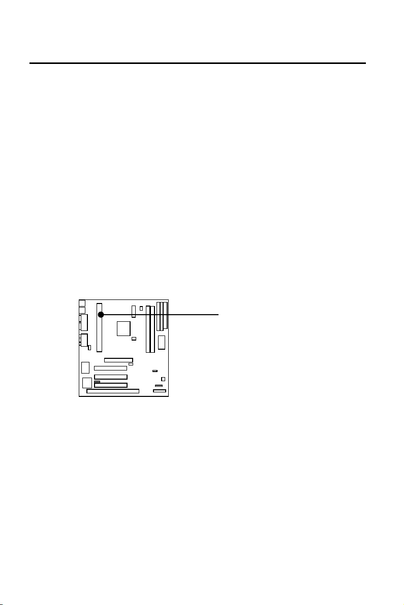
The motherboard provides a SLOT 1 for Pentium II CPU. The CPU
should have a fan attached to it to prevent overheating. If your CPU
did not come with a fan, then purchase a fan before you turn on your
system.
NOTE 1 : You must set the CPU External Clock (BUS) Frequency
Selection” and “CPU to BUS Frequency Ratio” depending
on the CPU that you install.
2 : Without a fan, the CPU can overheat and cause
damage to both the CPU and the motherboard.
SLOT 1
Page 13
Chapter 2 INSTALLATION
To install a CPU, locate the SLOT 1. Insert the CPU with the correct
orientation. you should have a CPU fan that will cover the face of the
CPU.
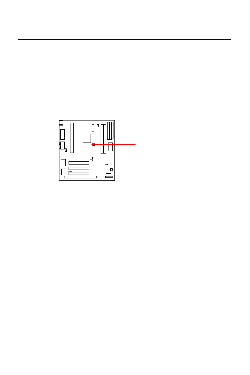
JP4 : (Use pin header )
CPU Host Clock Select
Note : The JP4 is CPU Speed Select Utilize Pin
Header, See The Page 25, 26 For Detailed
Description.
Page 14
Chapter 2 INSTALLATION
2-5 Expansion Cards & Slots
Assigning DMA Channels for ISA Cards:
Some ISA cards, both Legacy and PnP may also need to use a DMA
(Direct Memory Access) channel. DMA assignments for this
motherboard are handled the same way as the IRQ assignment process
. You can select a DMA channel in the PCI and PnP configuration
section of the BIOS Setup utility.
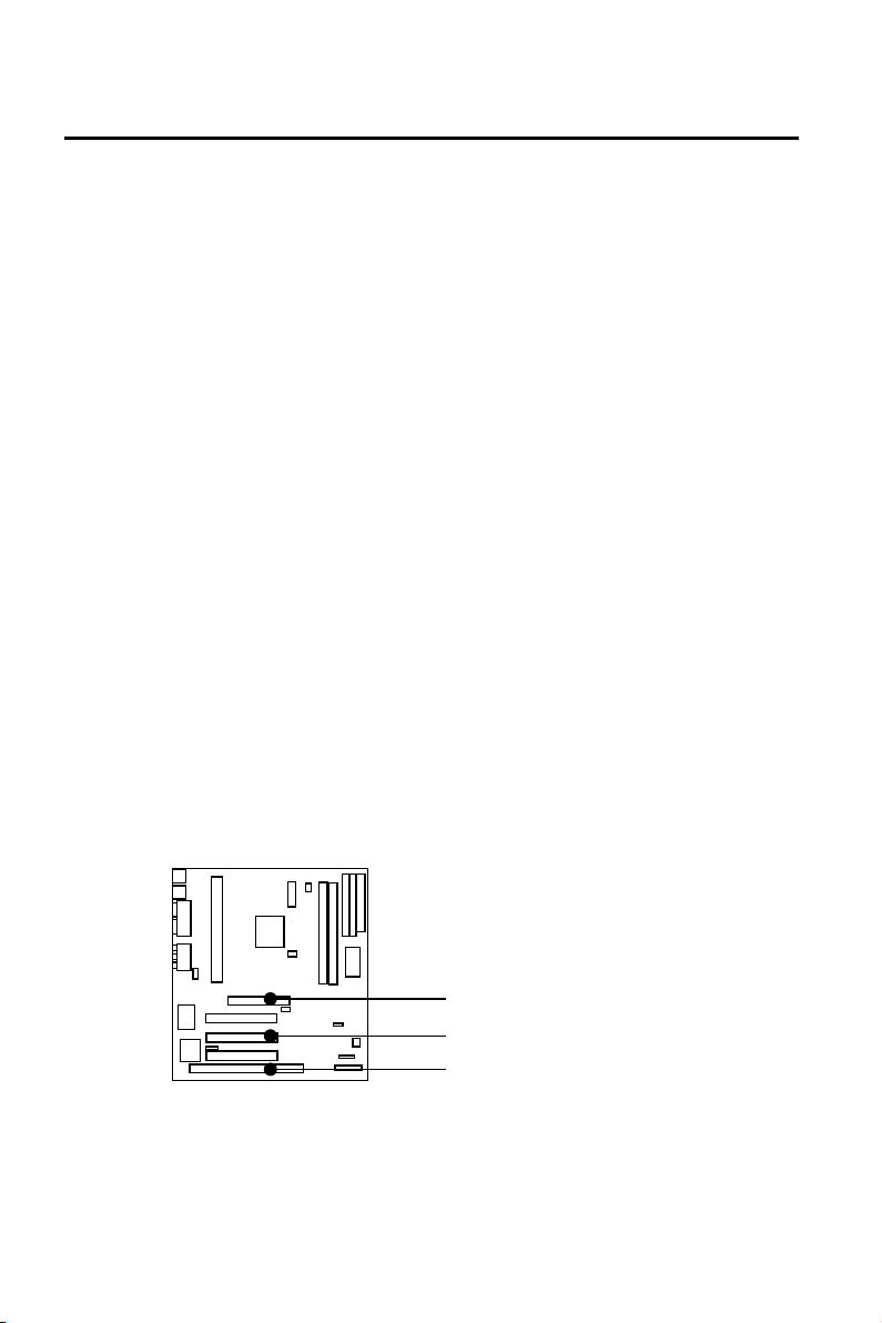
This motherboard provides an AGP (Accelerated Graphics Port) slot
to support a new generation of graphics cards with ultra-high memory
bandwidth. (Note : For the detail of AGP to see appendix)
NOTE: Choose “Legacy ISA” for those IRQ’s and DMA’s
you wish to reserve for Legacy (Non-PnP) ISA
expansion cards in “IRQ xx Used by ISA” and “DMA
x Used By ISA” of the PnP and PCI Setup in the
BIOS Software section, otherwise conflicts may
occur.
1 x AGP SLOT
3 x PCI SLOTS
1 x ISA SLOTS
Page 15
Chapter 2 INSTALLATION
2-6 External Connectors
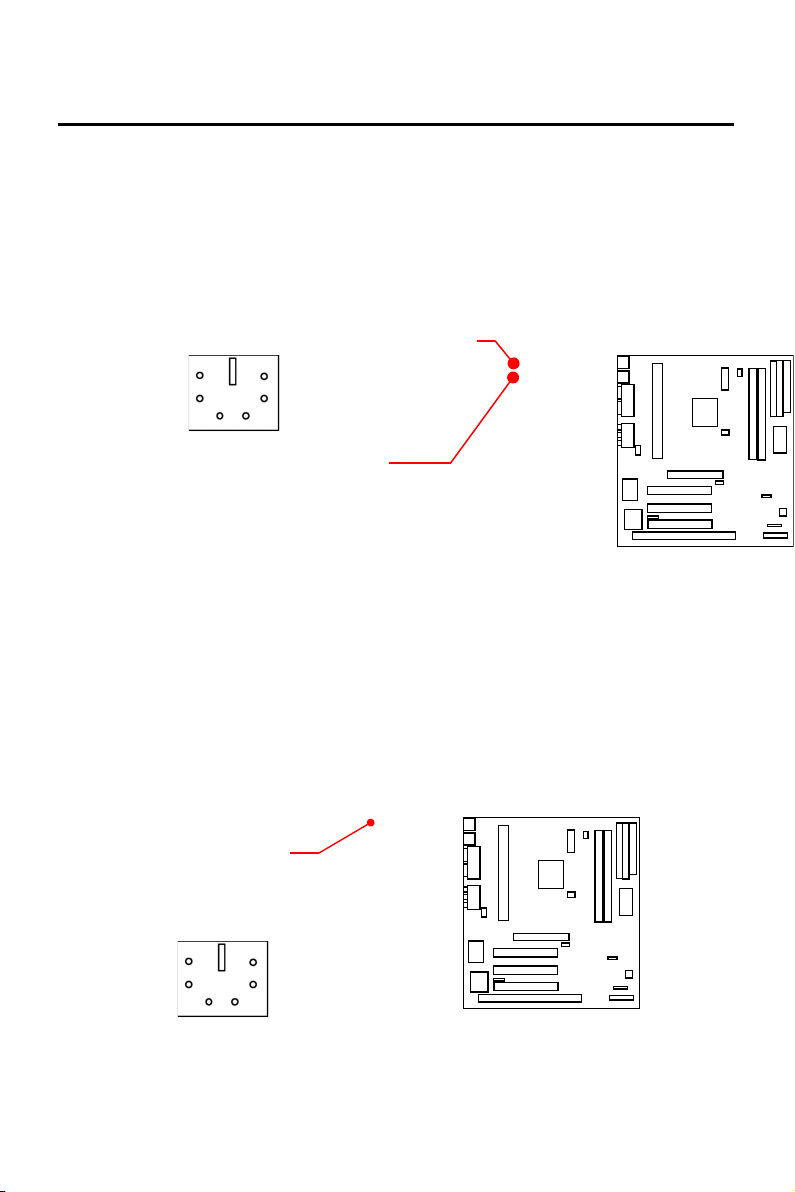
1. Keyboard Connector and USB Port (K/B, 6-pin Mini DIN
connector and USB, standard stack connector)
This K/B connection is for a PS/2 Keyboard connector, which is
on lower stack connector.
2. PS/2 Mouse Connector (PS/2, 6-pin Mini DIN Connector)
This Mouse connection is for a PS/2 Mouse connector, which is
on upper stack connector.
If you are not using a PS/2 mouse, you must disable the PS/2 port
in the BIOS Setup. <default is enable>
Note : The USB Port Support Standard USB Spec.
PS/2 Mouse
Connector
K/B : Keyboard
Port
USB Port
Page 16
Chapter 2 INSTALLATION
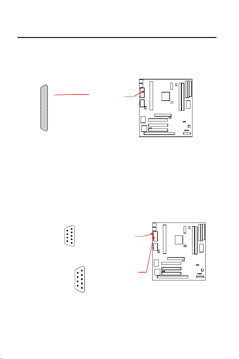
3. Parallel Port (CN7, 25-pin D-SUB connector)
You can enable the parallel port (LPT1) and choose the IRQ
through BIOS Setup on “Onboard Parallel Port”.
4. Serial Ports (COM1, COM2, 9-pin D-SUB connector).
The two serial (COM1 & COM2) ports can be used for pointing
devices or other serial devices. See “Onboard Serial Port” in
Chipset Features Setup of the BIOS Software.
Parallel Port
CN1:COM1
CN2:COM2
Page 17
Chapter 2 INSTALLATION
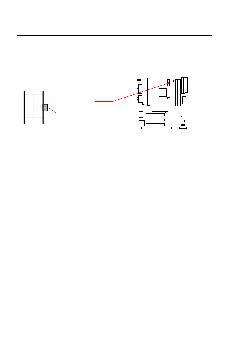
5. ATX Power Supply Connectors (ATXPWR1:20-pin block)
ATX is a standard ATX-type power connector. (The ATX
power connector can only be inserted the correct way.)
NOTE:
To prevent electrical spikes, make sure that the power
supply is not connected to an outlet when making or removing
connections. Power supplies contain power reserves that can
damage electrical components.
Key holder
ATX Power
Connector
Page 18
Chapter 2 INSTALLATION
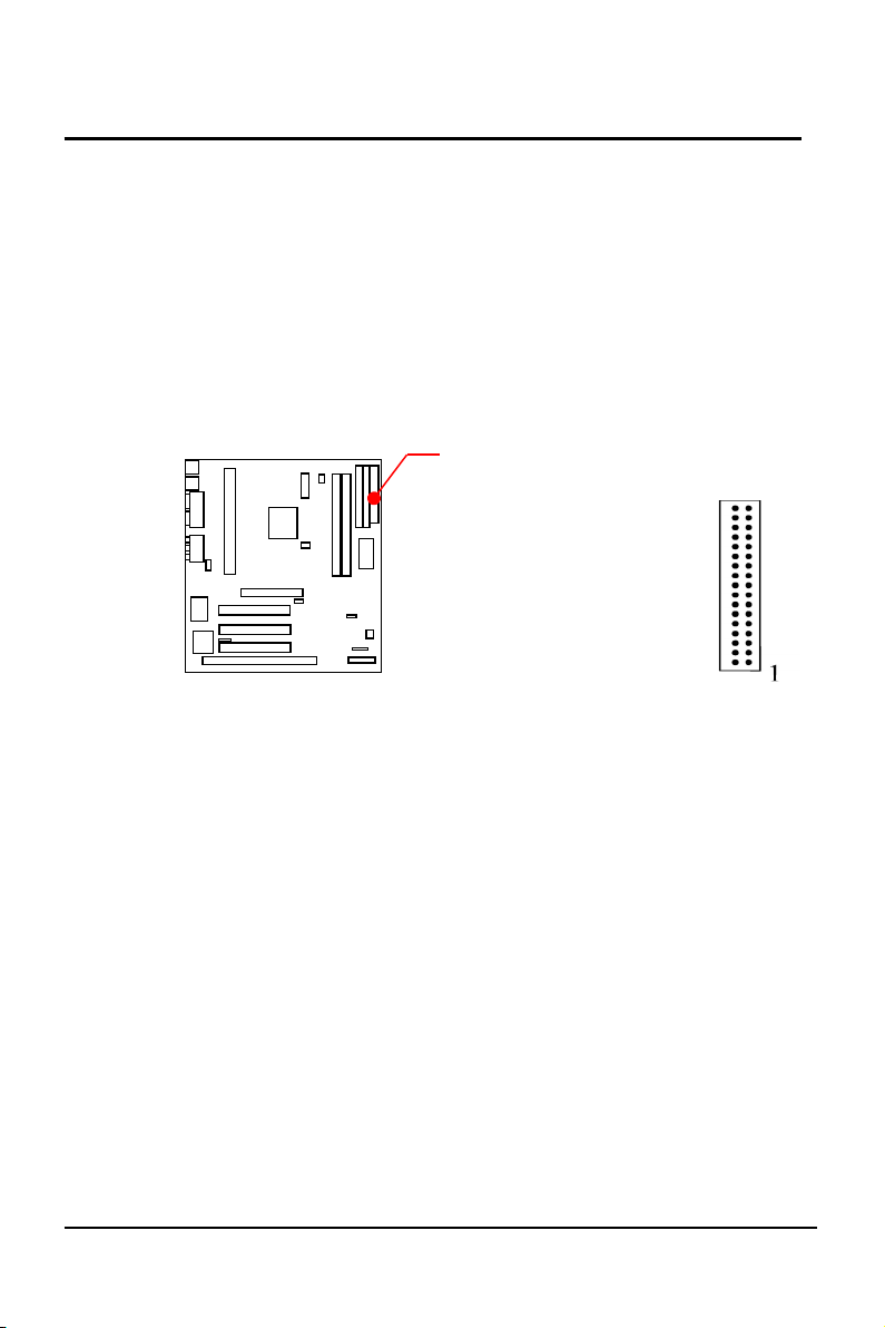
6. Floppy Drive Connector (FDD1, 34-pin Pin header)
This connector supports the provided floppy disk drive ribbon
cable. After connecting the single end to the board, connect
the plugs on the other end to one or two floppy drives. The
motherboard provides a standard floppy disk (FDD) connector
that supports 360K, 720K, 1.2M, 1.44M and 2.88M floppy
disk types. You can attach a floppy disk cable directly to this
connector.
EP-KE21 User’s Manual
FDD Connector
15
Page 19
16
Chapter 2 INSTALLATION
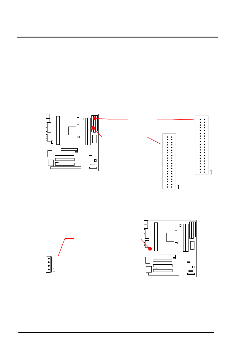
7. Primary/Secondary IDE connectors (IDE1 & IDE2: Two 40-
pin Pin header)
These connectors support the provided IDE hard disk ribbon
cable. After connecting the single end to the board, connect
the two plugs at the other end to your hard disk(s). If you
install two hard disks, you must configure the second drive to
Slave mode by setting its jumper accordingly. Please refer to
the documentation of your hard disk for the jumper settings.
8. CD-IN Connector (JP1: 4-pin Connector)
This connector supports CD-ROM Audio signal input from
CD-ROM driver.
EP-KE21 User’s Manual
IDE 1
IDE 2
CD-IN Connector
Pin # :
1. L-IN
2. GND
3. R-IN
4. GND
Page 20
Chapter 2 INSTALLATION
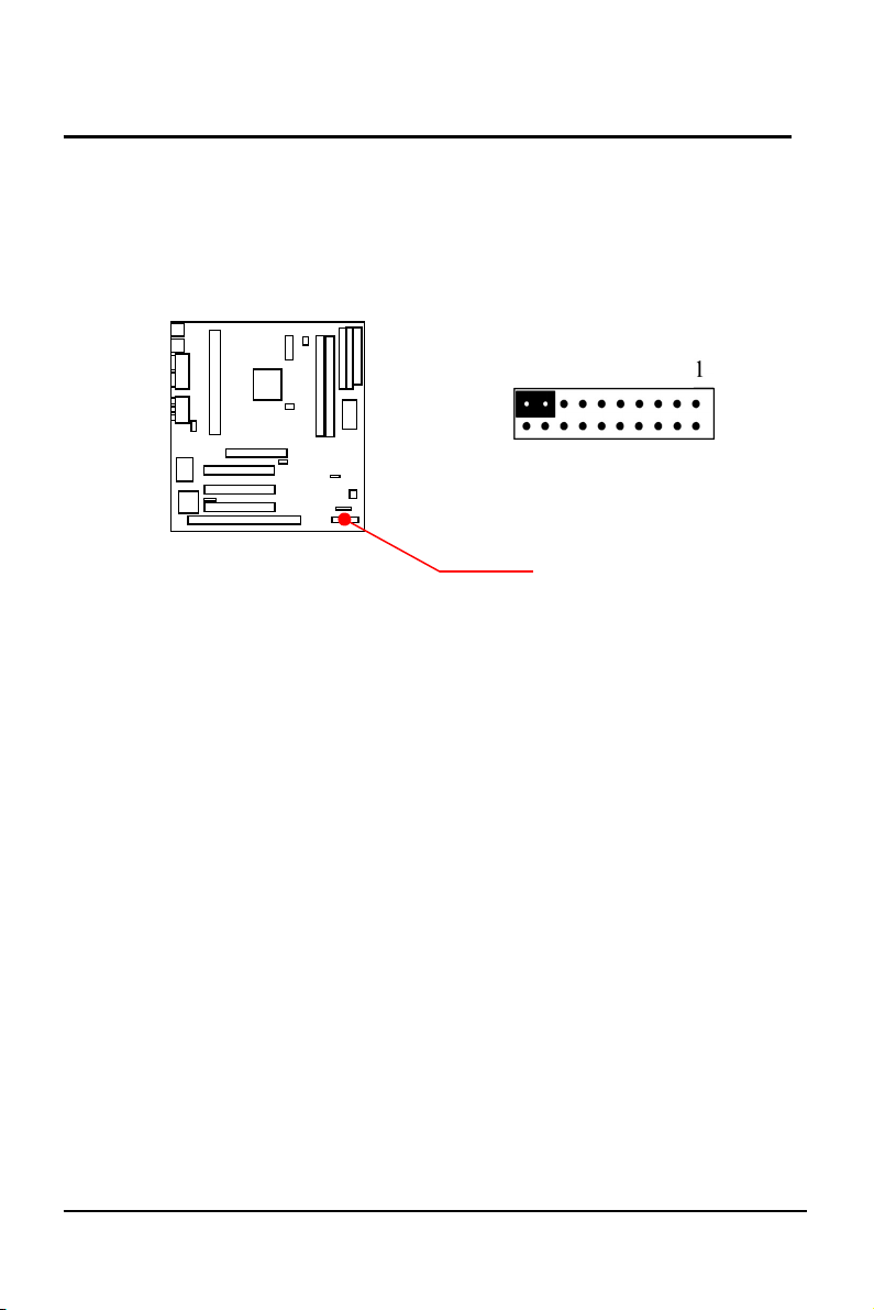
9. a. IDE Activity LED (J1, Pin 2, 4 )
This connector connects to the IDE (hard disk) activity
indicator light on the system cabinet.
EP-KE21 User’s Manual
J1, HDD LED
Pin 17 : +
Pin 19 : G
17
Page 21
18
Chapter 2 INSTALLATION
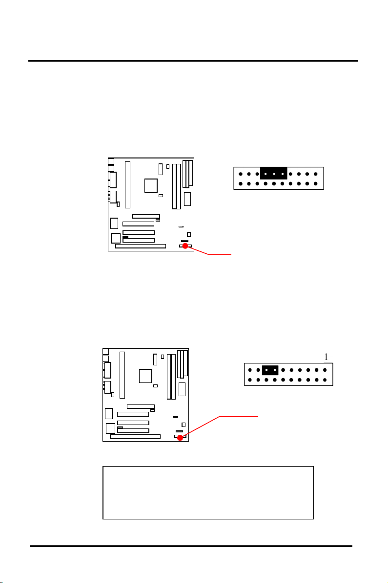
b. System Power LED (J1, Pin 9, 11, 13)
This 3-pin connector lights the system power LED when
the motherboard has power.
c. Turbo LED (J1, Pin 13, 15)
EP-KE21 User’s Manual
J1, System Power LED
Pin 13 : +
Pin 15 : G
- + +
If the cabinet provides the turbo LED cable,
connect the cable to this two pin connector to
turn on the LED on the front panel.
Page 22
Chapter 2 INSTALLATION
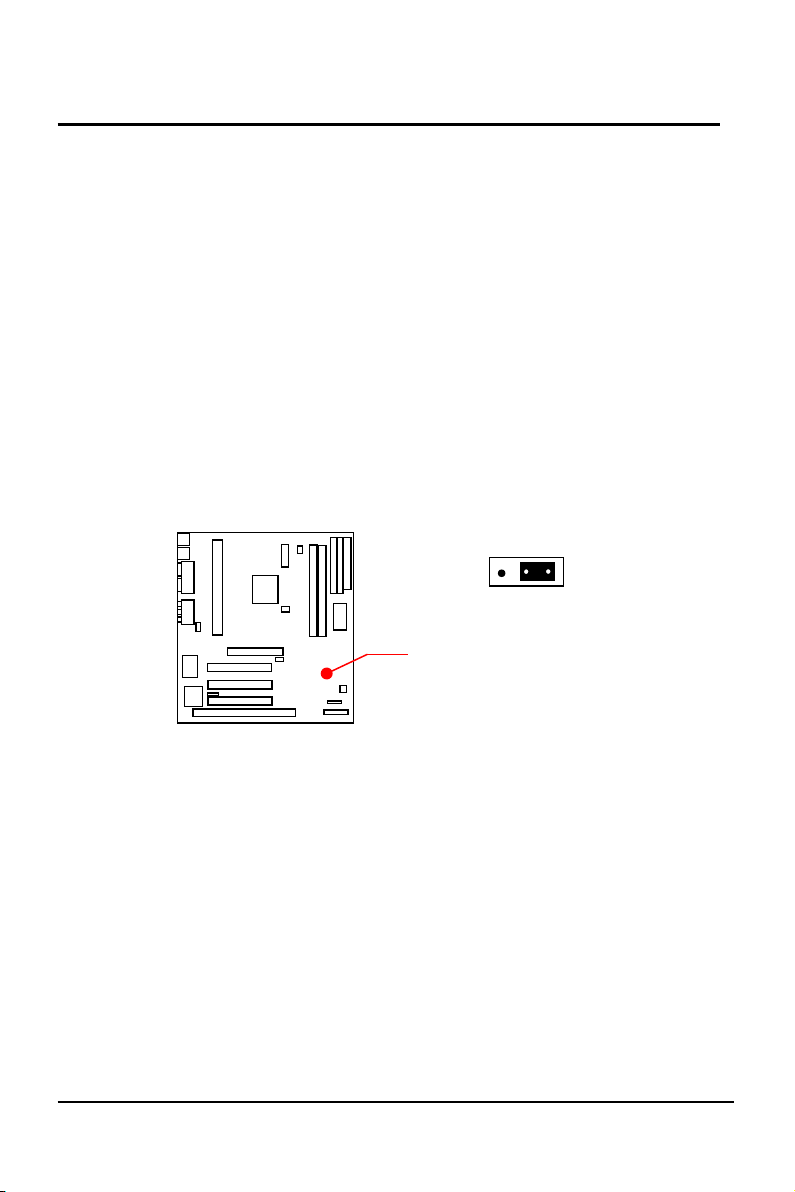
d. CMOS Clear ( JP3 )
The CMOS RAM is powered by the onboard button cell
battery.
You can follow process to clear the RTC data :
(a) Turn-off power of computer
(b) To put the pin cap locate at “Clear” for a while
(c) Reput the pin cap locate at “Normal”, and turn-
on computer power
(d) Hold down <Del> key during the system booting
and enter BIOS setup screen to re-keyin the users
setting.
EP-KE21 User’s Manual
1
Clear
Normal
JP3 : Clear CMOS
19
Normal : Pin 1,2 (Default)
Clear : Pin 2,3
Page 23
20
Chapter 2 INSTALLATION
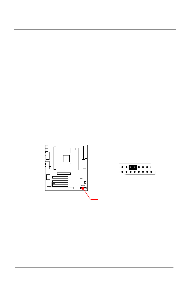
e. ATX Power Switch Lead ( J1, Pin 9, 11)
The system power is controlled by a push-switch,
connected to this lead. Pushing the button once will turn
on the power and pushing again will turn off the power.
The system power LED shows that status of the system’s
power. This connection does not have a function when a
standard power supply is used.
NOTE : If the power to the ATX power supply is interrupted
while the motherboard is on, standby power will
remember that the motherboard should be on and
boot the computer when power is reapplied to the
ATX power supply.
EP-KE21 User’s Manual
J1, Pin 9, 11:
ATX Power Switch On/ Off
Lead
Page 24
Chapter 2 INSTALLATION
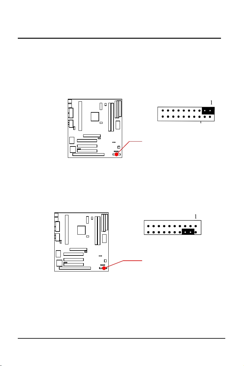
f. Reset Switch Lead (J1, Pin 1, 3)
This 2-pin connector connects to the case-mounted reset
switch for rebooting your computer without having to turn
off your power switch. This is a preferred method of
rebooting in order to prolong the life of the system’s power
supply.
g. Keyboard Lock Switch Lead
(J1, Pin 4, 6)
This 2-pin connector connects to the case-mounted
keyboard lock switch for locking the keyboard.
EP-KE21 User’s Manual
J1, Pin 1, 3:
Reset Switch Lead
J1, Pin 4, 6 :
KEYLOCK
1
21
1
2
Page 25
22
Chapter 2 INSTALLATION
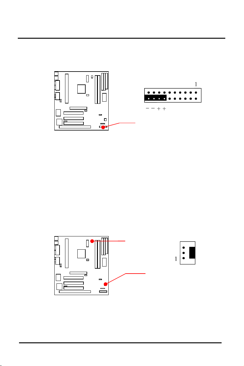
10. Speaker Connector (J1, Pin 14, 16, 18, 20)
This 4-pin connector connects to the case-mounted speaker.
11. CPU Cooling Fan Connector (FAN1&FAN2 : support fan
detect)
This connector supports a CPU cooling fan of 500 mA
(6WATT, +12V) or less. Orient the fan so that the heat sink fins
allow airflow to go across the onboard heat sink(s). Depending
on the fan manufacturer, the wiring and plug may be different.
The red wire should be positive, while the black should be
ground. Connect the fan’s plug to the board taking into
consideration the polarity of the connector.
EP-KE21 User’s Manual
J1, Pin 14, 16, 18, 20 :
Speaker Connector
FAN 2
FAN 1
Pin 1 : GND
Pin 2 : +12V
Pin 3 : Detect
Page 26
Chapter 2 INSTALLATION
NOTE: The CPU and/or motherboard will overheat if there
is no airflow across the CPU. Damage may occur to
the motherboard and/or the CPU fan if these pins are
incorrectly used. These are not jumpers, do not place
jumper caps over these pins.
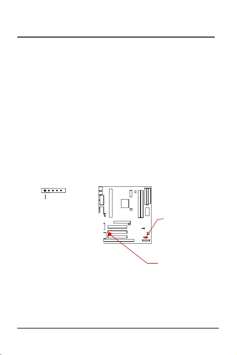
12. IrDA Compliant Infrared Module Connector (IR1, IR2)
This connector supports the optional wireless transmitting and
receiving infrared module. This module mounts to a small
opening on system cases that support this feature. You must
also configure UART 2. Use Infrared in Chipset Features Setup
to select whether UART 2 is directed for use with COM2 or
IrDA. When IrDA is selected in BIOS, COM2 will be disabled.
Use the five pins as shown and connect a wire cable from the
module to the motherboard to the pin definitions.
EP-KE21 User’s Manual
IR1 “FRONT IR”
2. FIRRX
1. +5V
IR2 “REAR IR”
23
Pin # :
5. IRTX
4. GND
3. IRRX
Page 27
24
Chapter 2 INSTALLATION
2-7 Hardware Jumper Setup
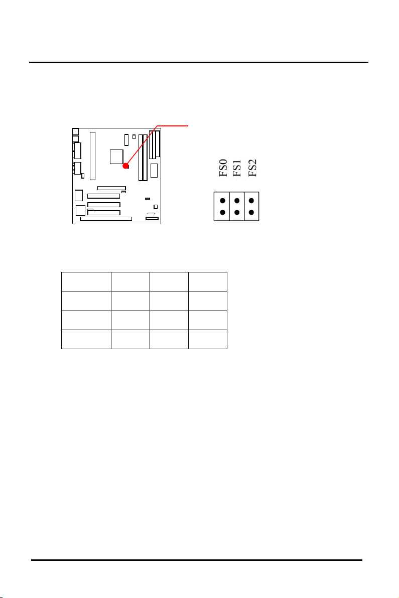
8. External HCLK Frequency Select
FS0 FS1 FS2
68.5MHz OFF OFF ON
75 MHz OFF ON OFF
83.3MHz ON OFF ON
EP-KE21 User’s Manual
JP4 : HCLK Select
Page 28
Chapter 2 INSTALLATION
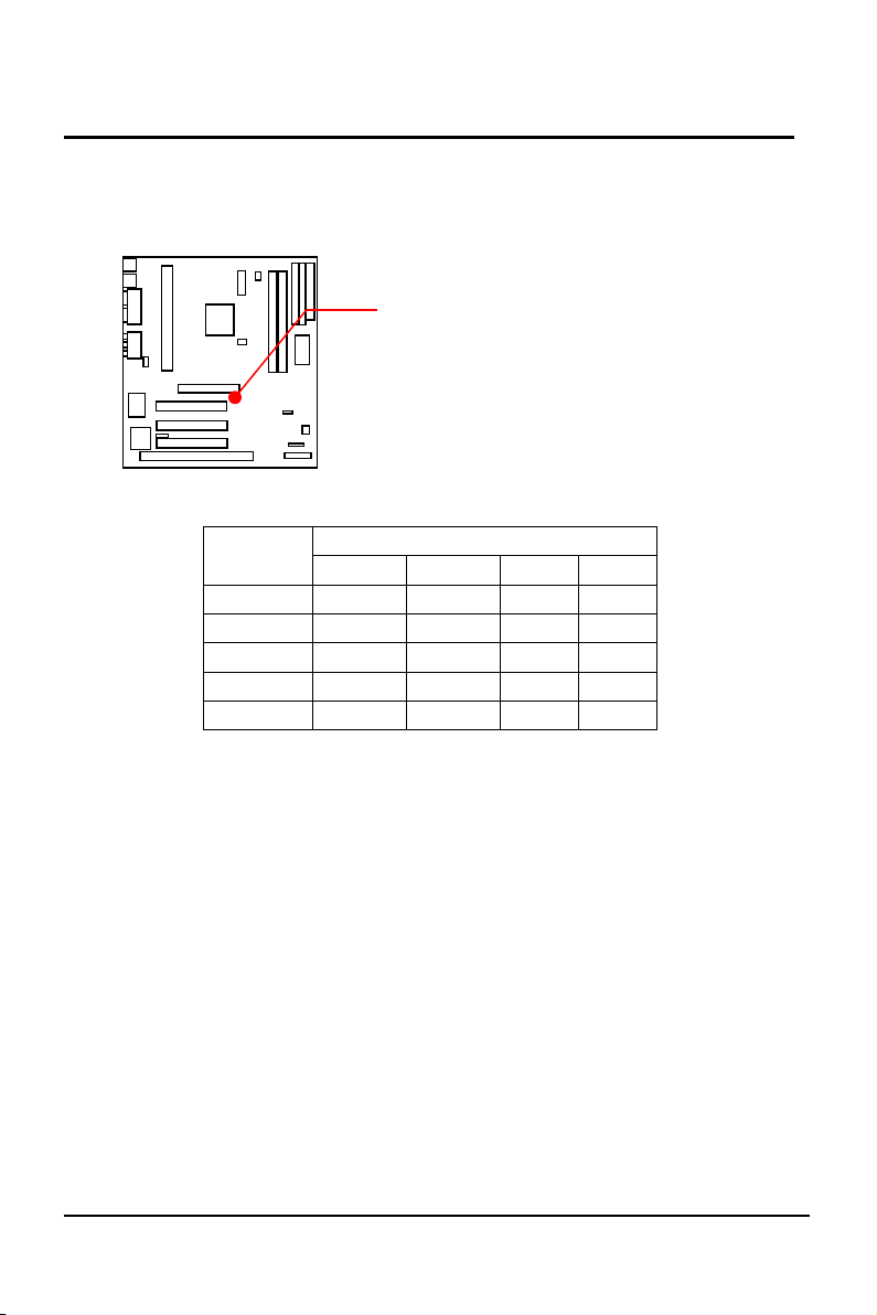
9. Frequency Ratio Select Table (JP2)
RATIO
JP2
1 2 3 4
X3.5 ON OFF OFF ON
X4.0 OFF ON ON ON
X4.5 OFF ON OFF ON
X5.0 OFF OFF ON ON
X5.5 OFF OFF OFF ON
NOTE :
1. On : Install Pin Cap,
2. Off : Uninstall Pin Cap
EP-KE21 User’s Manual
JP2 : Ratio Select
25
Page 29
26
Chapter 2 INSTALLATION
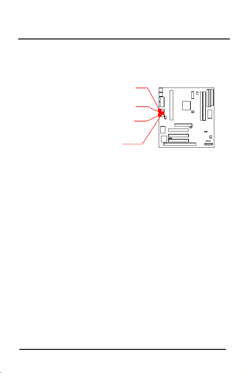
10. Audio Jack & Game Port
This jack and MIDI/Game port is stack connector to support
LINE-IN, LINE-OUT, MIC-IN and 15-pin D-SUB Connector
for joy stick or MIDI player
EP-KE21 User’s Manual
LINE-IN
LINE-OUT
MIC-IN
MIDI/Game Port
Connector
Page 30

Chapter 3 SPECIAL FEATURE
3-1. Security Keyboard and Mouse Power On
The Winbond W83977TF-AW is a new IC whose keyboard and
mouse controller (KBC) is enhanced with “Programmable OnNow /
Security Wake-Up” feature. It provides the function that users can
wake up a shutdown PC system simply by a keystroke or a click of
mouse button. This is a perfect implementation of OnNow. Users are
able to program a combination of 1-5 characters as the password. By
choosing the "INTEGRATED PERIPHERALS" option from the
CMOS SETUP UTILITY Menu to enable or disable the following
features :
1, Password. 2, Hot kEY. 3, BUTTON ONLY
4, Mouse Left. 5, Mouse Right.
3-2. Modem Ring / LAN Wake-Up
This feature is able to wake-up the system from Modem or LAN
when the PC system is suspended to memory through ACPI but not
powered off. You have to choose "POWER MANAGEMENT
SETUP" option from the CMOS SETUP UTILITY Menu to enable
or disable this feature.
3-3. Hardware Monitoring
This motherboard provided a hardware status monitoring IC for
personal computers to monitor several critical hardware parameters of
the system, including power supply voltages, fan speeds, and
temperatures. The users can read all the monitored parameters of
system from time to time. The application software could be the
popular Intel LDCM (LANDesk Client Management) or Winbond's
application software. Also the users can setup the upper and lower
limits of these monitored parameters and to activate two
programmable and maskable interrupts. An optional beep tone could
be used as warning signal when the monitored parameters are out of
the preset ranges.
Page 31

Chapter 4 APPENDIX
A, What is AGP (Accelerated Graphics Port) ?
The Accelerated Graphics Port (AGP) is a new port on the
Host–To–PCI bridge device that supports an AGP port. The main
purpose of the AGP port is to provide fast access to system
memory.
The AGP port can be used either as fast PCI port (32-bits at
66MHz VS. 32-bits at 33MHz) or as an AGP port which supports
2x data rate, a read queue, and side band addressing. When the 2x
date is used the port can transmit data at 533MB/sec. (66.6 2
4). The read-queue can be used to pipline reads removing the
effects of the reads latency. Side band addressing can be used to
transmit the data address on a separate line in order to further speed
the transaction.
Page 32
Chapter 3 SPECIAL FEATURE
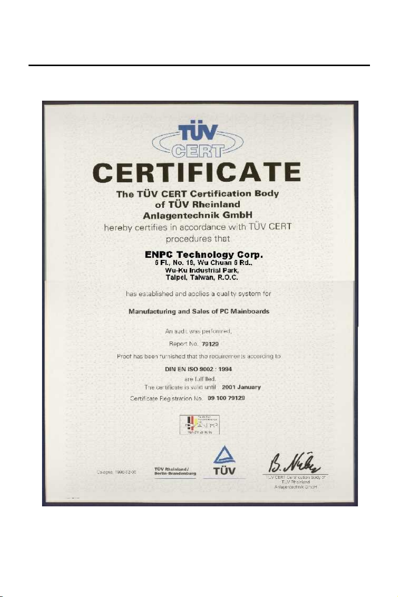
B, ISO-9002 QA CERTIFICATE
Page 33

Chapter 4 APPENDIX
Page 34

100
POST-CONSUMER
RECYCLED PAPER
EP-KE21
User’s Manual
 Loading...