

Page 1

Main Board
KB21 User’s Manual
Released Date : Sep. 1998
User’s Manual Version : 1.4
Page 2

Main Board
AB-641 User’s Manual
Released Date : Sep. 1998
User’s Manual Version : 1.4
Page 3

User’s Manual Rev. 1.4
CONTENTS
I. INTRODUCTION...................................................................… 2
How this manual is organized ...........................................…..... 2
Item Checklist..............................................................………… 2
II. FEATURES…………………………………………………….…… 3
Specification of the Motherboard ......……….........……………… 3
Feature of the Motherboard ….……..........…………….………… 5
III. INSTALLATION.....................................................................… 6
Motherboard Layout .......…………….....................…..……….... 6
1. Jumpers Setting........................................................…... 8
2. Install System Memory Module....................................… 9
3. Install the CPU………………………………...............…... 10
4. Install the Expansion Cards…………… .......................... 12
Assigning IRQs for Expansion Cards.............................. 13
Assigning DMA Channels for ISA Cards......................... 14
5. External Connection........................................................ 15
6. Power on Procedures .......................................…………. 21
IV. BIOS SETUP Tips ...................................................................... 22
V. FAQ of this Mother Board ………………………………………... 31
VI. Year 2000 (Y2K) Compliant ……………………………………….. 32
1
Page 4

User’s Manual Rev. 1.4
I. INTRODUCTION
How this manual is organized
This manual is divided into the following sections:
I Introduction : Manual information and checklist
II. Features : Information and specifications concerning this product
III. Installation : Instructions on setting up the motherboard
IV. BIOS Setup : Instructions on setting up special feature in the BIOS
Item Checklist
Please check that your package is complete. If you discover damaged or
missing items, please contact your retailer.
Motherboard x 1
40-pin IDE Connector Flat Cable x 1
34-pin Floppy Disk Drive Flat Cable x 1
User’s Manual x 1
CD x 1
LDCM Diskette x 1 (Option)
USB Connector Cable with bracket x 1 (Option)
IrDA Module x 1 (Option)
Option : Components will be include upon customer ordering instructions
per Proforma Invoice & additional external procurement cost will
be included.
2
Page 5

II FEATURES
Specifications
The motherboard is designed with the Intel 82443BX PCI chipset which is
developed by Intel Corporation to fully support the Pentium II Processor
PCI/ISA system. The Intel 82443BX PCI chipset provides increased
integration and improved performance designs. The chipset provides an
integrated IDE controller with two high performance IDE interfaces for up
to four IDE devices (hard devices, CD-ROM device, etc). The Super I/O
controller provides the standard PC I/O function: floppy interface, two
16Byte FIFO serial ports and EPP/ECP capable parallel port. Care must
be taken when inserting memory modules, inserting CPU or even
plugging PCI card into associated slots to avoid damaging any circuits or
sockets on board. A cooling fan is strongly recommended. The
motherboard supports minimum of 8MB of system memory and a
maximum of 1GB SDRAM.The motherboard provides Four 168-pin DIMM.
The socket supports 1Mx32 (32MB) single-sided or double-sided memory
modules. The board also supports two onboard PCI IDE connectors, and
detects the IDE hard disk type by the BIOS utility which is automatic. The
system also supports Award Plug & Play BIOS for the ISA and PCI cards.
Processor:
Slot 1 support Intel Pentium II with MMX Series CPU’s, CPU Clock
Select support for 66 MHz and up to 112 MHz CPU Bus speed
configuration.
Chipset:
Intel 82443BX System Controller
Intel 82371EB PCI/ISA IDE Accelerator
BIOS
Award BIOS With Flash ROM, support PnP, PCI 2.1, CD-ROM, ATAPI, LS120, and any IDE Device Bootable, Virus Protection, DMI Ready
System Memory:
3 x 168-pin DIMM Slots Support Mixed Memory Technologies: Extended
Data Output (EDO), Fast Page (FP) DRAM, Synchronous DRAM (SDRAM)
Multi-I/O Onboard:
1 x FDD Port support up to 2.88MB
1 x Parallel Port (LPT) support ECP/EPP
Page 6

2 x High Speed Serial (16C550 UART) Ports
2 x Universal Serial Bus (USB) Ports
1 x PS/2 Keyboard Port
1 x PS/2 Mouse Port
2 x IrDA Infrared Interfaces
PCI Bus Master IDE:
PCI Enhanced IDE Interface with 4 IDE Devices
Support HDD Auto-Detect
Support up to PIO Mode 4, DMA Mode 2
Support Ultra DMA/33 mode
Fully compatible with PCI Local Bus Specifications V2.1
ATX Stack Connector:
2 x USB Ports, 1 x PS/2 Keyboard Port, 1 x PS/2 Mouse Port, 1 x Parallel
Port, 2 x Com Port
Expansion Slots:
3 x 16-bit ISA Slots with 100% ISA Compatible Functions
4 x 32-bit PCI Slots supporting PCI BUS Master Slots Conform with PCI
Specifications Version 2.1
1 x AGP Slot supported.
Options:
2 x Infrared (IrDA) Wireless Interface Kit (Front & Rear)
Universal Serial Bus (USB) Connector Kit
Winbond W83781D (Register compatible with LM78/75 ) Hardware Monitor
/ CPU Temperature reading Circuit Design, LDCM for system Voltage,
System Temperature, Fan Speed detect.
Dimension: 305 mm x 190 mm
Form Factor: ATX Form Factor with double stack connector design
Page 7

II. FEATURES
ACPI Ready –
ACPI (Advanced Configuration and Power Interface) is also
implemented on this motherboards. ACPI provide more Energy Saving
Features for the future operating systems (OS) supporting OS Direct
Power Management (DPM) functionality. With these features
implemented in the OS, PCs can be ready around the clock everyday,
yet satisfy all the energy saving standards. To fully utilize the benefits
of ACPI, an ACPI-supported OS such as in the next release of
Windows 95/98 must be used.
PC '97 Compliant –
Both the BIOS and hardware levels of smart series of motherboards
meet PC '97 compliance. The PC 97 requirements for systems and
components are based on the following high-level goals: Support for
Plug and Play compatibility and power management for configuring
and managing all system components, and 32-bit device drivers and
installation procedures for both Windows 95/98 and Windows NT.
Temperature Monitoring and Alert –
To prevent system overheat and system damage, there are heat
sensors to monitor the CPU and system temperatures to warn of
damaging temperatures.
Voltage Monitoring and Alert –
System voltage levels are monitored to ensure stable current to critical
motherboard components. Voltage specifications are more critical for
future processors, so monitoring is necessary to ensure proper system
configuration and management.
Modem Ring On –
This allows a computer to be turned on remotely through an external
modem. With this benefit on-hand, any user can access vital
information from their computer from anywhere in the world.
Wake ON LAN –
This main board implements a LAN-Wake UP connector, to use LAN
Wake-up function, user need a network card that supports this feature.
In addition, user also needs to install network management software,
such as LDCM. The connector will receive a wakeup packet or signal
from LAN Card to power up the system.
Sometimes, the external MODEM just power ON/OFF, the pulse
will be taken as the Ring in signal, which will make the machine
power up. User needs to pay more attention about this
symptom.
Page 8
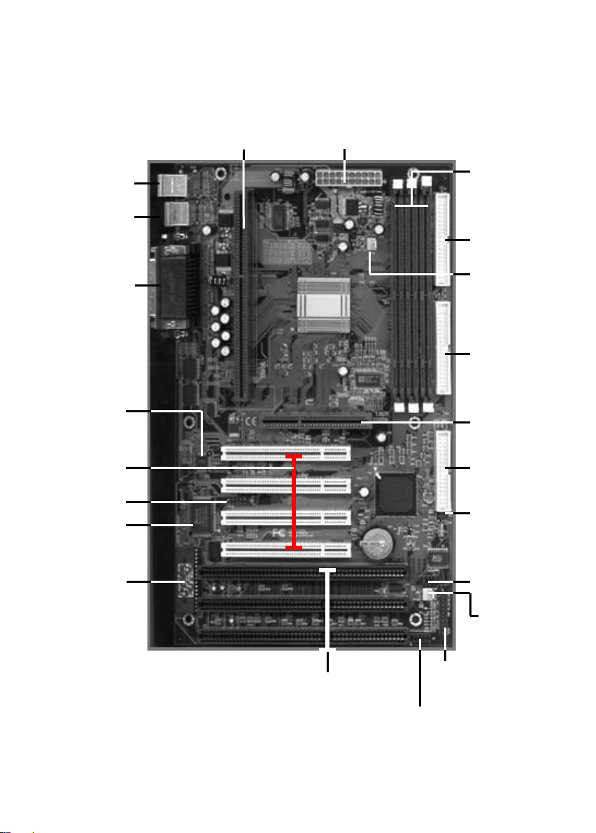
III. INSTALLATION
Keyboard
Mouse
ATX Power Supply
Primary
IDE
COM 2
LPT
COM 1
W83781D
( Option)
4 x PCI
Slots
I/O Chip
CPU FAN 1
Secondary
IDE
CMOS
Clear
CPU FSB
Clock
CPU
FAN 2
Front Panel
Connector
Page 9
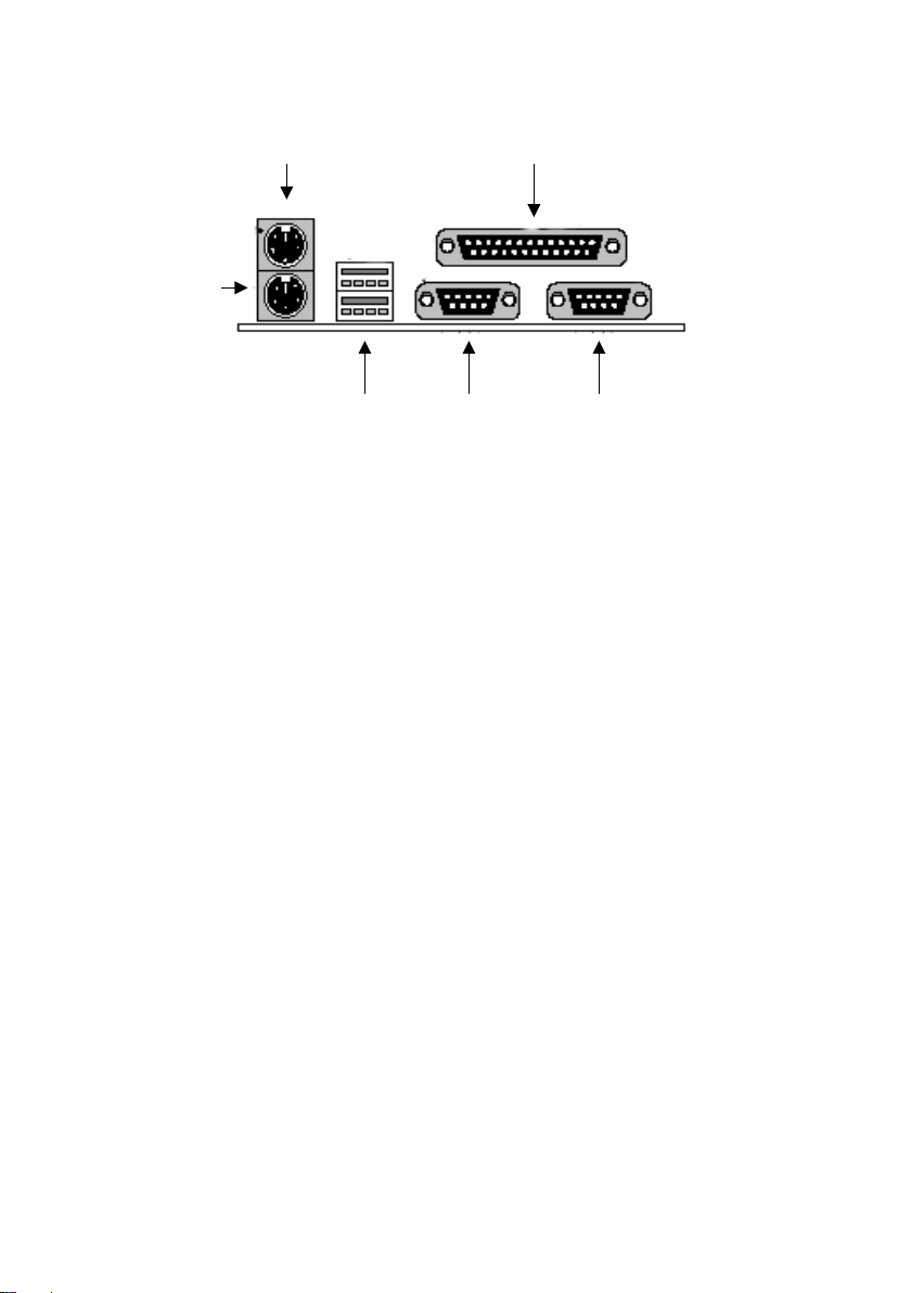
Keyboard
Front Panel
Connector
Page 10
III. INSTALLATION
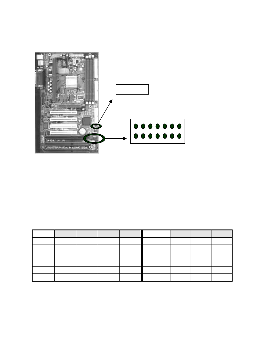
III-1 Jumpers Setting
1 2 3
CMOS Clear:
1 – 2 Normal
2 – 3 Clear
1). CMOS Clearing
CMOS Clear, which is a safety hook if you forget the password. Follow the
steps:
After you have turned off your computer, clear the CMOS memory by
momentarily shorting pins 2-3, for a few seconds. Then restore it to the
initial 1-2 jumper setting in order to recover and retain the default settings.
Reset your computer now.
2). External HCLK Frequency Setup
Ratio 1 2 3 4 BUS CLK 5 6 7
3.0 ON OFF ON ON 112 MHz OFF ON OFF
3.5 ON OFF OFF ON 100 MHz OFF OFF OFF
4.0 OFF ON ON ON 83 MHz ON OFF ON
4.5 OFF ON OFF ON 75 MHz ON ON OFF
5.0 OFF OFF ON ON 66 MHz ON OFF OFF
5.5 OFF OFF OFF ON
1 2 3 4 5 6 7
J3:
CPU Clock
Setting
Page 11
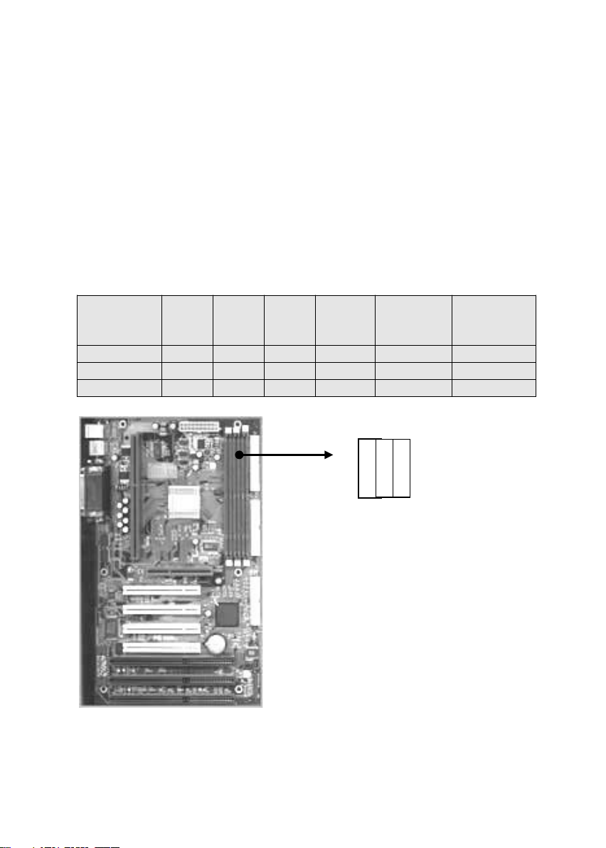
III-2 Install System Memory Modules
This motherboard support 3 slots for 168-pin 3.3V Non-buffered DIMM
modules, providing support for up to 1GB of main memory using DIMM
modules from 8MB to 256MB. For 66MHz host bus CPUs, please use 12ns
or faster DIMM modules. For 100MHz host bus CPUs, please use 8ns or
faster DIMM modules. The following is the example to install the system
SDRAM memory module combination: if you have two DIMM Modules, you
has better install them into DIMM Slot 1 & Slot 2 with the Max possible
memory size up to 256MB ( 128 + 128 ) if the 128MB DIMM module is
available.
Number Of
Memory
Module
DIMM1 DIMM2 DIMM3 DIMM4
Memory
Module Max. Size
1 1 st 8~128MB 128 MB
2 1 st 2 nd 8~128 MB 256 MB
3 1 st 2 nd 3 rd 8~128 MB 384 MB
DIMM 1 2 3
The DIMM types supported SDRAM
(Synchronous DRAM). The following is the
summary:
Single side:
1Mx64 (8MB), 2Mx64 (16MB), 4Mx64
(32MB), 8Mx64 (64MB), 16Mx64 (128MB)
Double side:
1Mx64x2 (16MB), 2Mx64x2 (32MB),
4Mx64x2 (64MB), 8Mx64x2 (128MB).
Total Memory Size:
There is no jumper setting required for the
memory size or type. It is automatically
detected by the system BIOS, and the
total memory size is to add them together.
D
Page 12
III-3 Install the Central Processing Unit (CPU)
The following table is the recommendation for the CPU setting with the
Frequency and the Ratio. Please refer to the related jumper setting
with the J3 in the page 8.
CPU Host Cock
(MHz)
X Multiplier = CPU Frequency (MHz)
66 X 3.5 = 233
66 X 4.0 = 266
66 X 4.5 = 300
66 X 5 = 333
100 X 3 = 300
100 X 3.5 = 350
100 X 4 = 400
100 X 4.5 = 450
100 X 5 = 500
Notes:
If you want to Over-Clock the CPU, please make sure the other
peripherals can work fine with one another. That mean you need to
well test the whole system with your own configuration, otherwise,
please set the default and safe setting with 66MHZ or 100MHZ front
side bus.
Install the CPU on the Motherboard
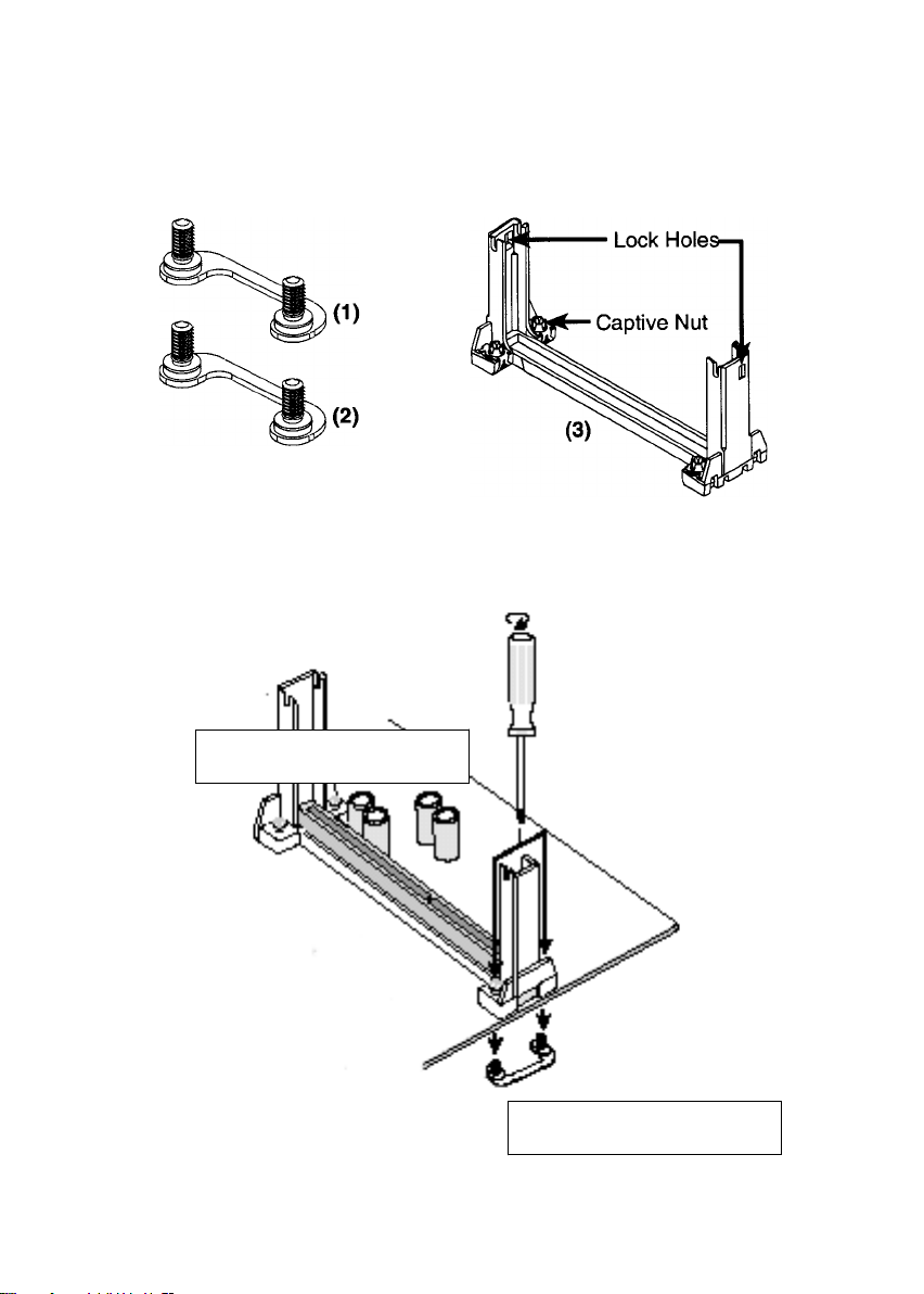
1. Insert the attach mount bridges (For the remaining instructions) into
the bottom of the mainboard with the curved edges facing outwards,
toward the edge of the mainboard.
2. Use a screw driver to lightly tighten the attach mount bridges and the
Pentium II Retention Mechanism
3. Insert the Pentium II processor into the Pentium II retention Mechanism
with the processor Heatsink. Press evenly and gently until the snaps on
the upper side of the processor have been inserted into the holes at the
top of the retention base. Note that when removing the processor, these
snaps can be clicked into a completely vertical position, leaving your
hands free to stabilize the board and pull the processor evenly and
gently out of the board. Also note that like PCI and ISA slots, Slot 1 has a
divider that prevents backwards insertion.
4. Attach the Thermal Sensor (optional): If you purchased the specially
designed thermal sensor, you can contact the thermal sensor to the CPU
Heatsink as nearest as possible.
Page 13
Install the CPU on the Motherboard
NOTE: The pictures in the following pages will have the same item
numbers next to them for your reference. The design and color of your
items may be slightly different.
Attach Mount Bridges
(Items 1,2)
Pentium II Retention Mechanism
(Item 3)
Retention Mechanism
Attach mount bridges
Page 14
III-4 Install Expansion Cards
Expansion Card Installation Procedure
Read the documentation for your expansion card and make any
necessary hardware or software settings for your expansion card,
such as jumpers.
Remove your computer system's cover and the bracket plate on the
slot you intend to use. Keep the bracket for possible future use.
Carefully align the card's connectors and press firmly.
Secure the card on the slot with the screw you removed above.
Replace the computer system's cover.
Set up the BIOS if necessary (such as IRQ xx Used By ISA: Yes in
PNP AND PCI SETUP)
Install the necessary software drivers for your expansion card.
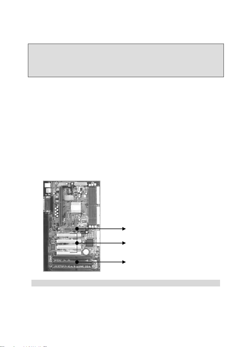
This motherboard also provides an AGP (Accelerated Graphics Port)
slot to support a new generation of graphics cards with ultra-high
memory bandwidth.
WARNING!
Unplug your power supply when adding or removing expansion cards or
other system components. Failure to do so may cause severe damage to
both your motherboard and expansion cards.
AGP Slot
4 PCI Slots
Page 15

Install Expansion Cards Tips:
Assigning IRQs for Expansion Cards:
Some expansion cards need to use an IRQ to operate. Generally an IRQ
must be exclusively assigned to one use. In a standard design there are 16
IRQs available but most of them are already in use, leaving 6 IRQs free for
expansion cards.
Both ISA and PCI expansion cards may require to use IRQs. System IRQs
are available to cards installed in the ISA expansion bus first, then any
remaining IRQs are available to PCI cards. Currently, there are two types of
ISA cards. The original ISA expansion card design, now referred to as
legacy ISA cards, requires that you configure the card's jumpers manually
and then install it in any available slot on the ISA bus. You may use
Microsoft Diagnostics (MSD.EXE) utility located in the Windows directory to
see a map of your used and free IRQs. If you use Windows 95/98, the
Resources tab under Device Manager displays the resource settings being
used by a particular device (to gain access, double-click the System icon
under the Control Panel program). Ensure that no two devices share the
ame IRQs or your computer will experience problems when those two
devices are in use at the same time. The original ISA expansion card
design, now referred to as "Legacy" ISA cards, requires that you configure
the card's jumpers manually and then install it in any available slot on the
ISA bus. You may use Microsoft's Diagnostic (MSD.EXE) utility included in
the Windows directory to see a map of your used and free IRQs. For
Windows 95/98 users, the "Control Panel" icon in "My Computer," contains
a "System" icon which gives you a "Device Manager" tab. Double clicking
on a specific device give you "Resources" tab which shows the Interrupt
number and address. Make sure that no two devices use the same IRQs or
your computer will experience problems when those two devices are in use
at the same time. To simplify this process this motherboard has complied
with the Plug and Play (PnP) specification which was developed to allow
automatic system configuration whenever a PnP-compliant card is added to
the system. For PnP cards, IRQs are assigned automatically from those
available. If the system has both Legacy and PnP ISA cards installed, IRQs
are assigned to PnP cards from those not used by Legacy cards. The PCI
and PnP configuration of the BIOS setup utility can be used to indicate
which IRQs are being used by Legacy cards. For older Legacy cards that
do not work with the BIOS, you can contact your vendor for an ISA
Configuration Utility. An IRQ number is automatically assigned to PCI
expansion cards after those used by Legacy and PnP ISA cards. In the PCI
bus design, the BIOS automatically assigns an IRQ to a PCI slot that has a
card in it that requires an IRQ. To install a PCI card, you need to set
something called the INT (interrupt) assignment. Since all the PCI slots on
Page 16

this motherboard use an INTA #, be sure that the jumpers on your PCI
cards are set to INT A.
Assigning DMA Channels for ISA Cards
Some ISA cards, both legacy and PnP, may also need to use a DMA
(Direct Memory Access) channel. DMA assignments for this motherboard
are handled the same way as the IRQ assignment process described
earlier. You can select a DMA channel in the PCI and PnP configuration
section of the BIOS Setup utility.
IMPORTANT:
To avoid conflicts, reserve the necessary IRQs and DMAs for legacy ISA
cards (under PnP AND PCI SETUP of the BIOS SOFTWARE, choose Yes
in IRQ xx Used By ISA and DMA x Used By ISA for those IRQs and DMAs
you want to reserve).
Notes:
If you have the problem to install the Windows 95 /98, maybe
system hung up or something wrong, the installation can’t
complete. Please try the following step:
1. Remove all the Add-ons, only remain the Display Card.
2. Set the BIOS default value.
3. Re- Install the OS ( Windows 95 or Windows 98. )
4. After completely install the OS, add the other expansion cards
one by one.
If your system can’t power on or no display, you may do the
following step to verify the problem:
1. Check the jumper on the Mother Board.
2. Set the BIOS to default value.
3. Remove all the add-ons only remain the VGA Card.
4. Change the VGA Card with different Slot.
5. Change the DIMM module.
6. Remove all the HDD, FDD Cable.
Page 17
III-5 External Connection
Important:
1. Ribbon cables should always be connected with the red stripe on the
Pin 1 side of the connector. The Four Corners of the connectors are
labeled on the motherboard. Pin 1 is the side closest to the power
connector on hard drives and floppy drives. IDE ribbon cable must be
less than 18in. (46cm), with the second drive connector no more than
6in. (15cm) from the first connector.
2. The motherboard requires a power supply with at least 250 Watts and a
"power good" signal. Make the ATX power supply can take at least
10mAmp load on the 5V Standby lead (5VSB) to meet the standard
ATX specification.
3. To prevent electrical spikes, make sure that the power supply is not
connected to an outlet when making or removing connections. Power
supplies contain power remains, which can damage electrical
components.
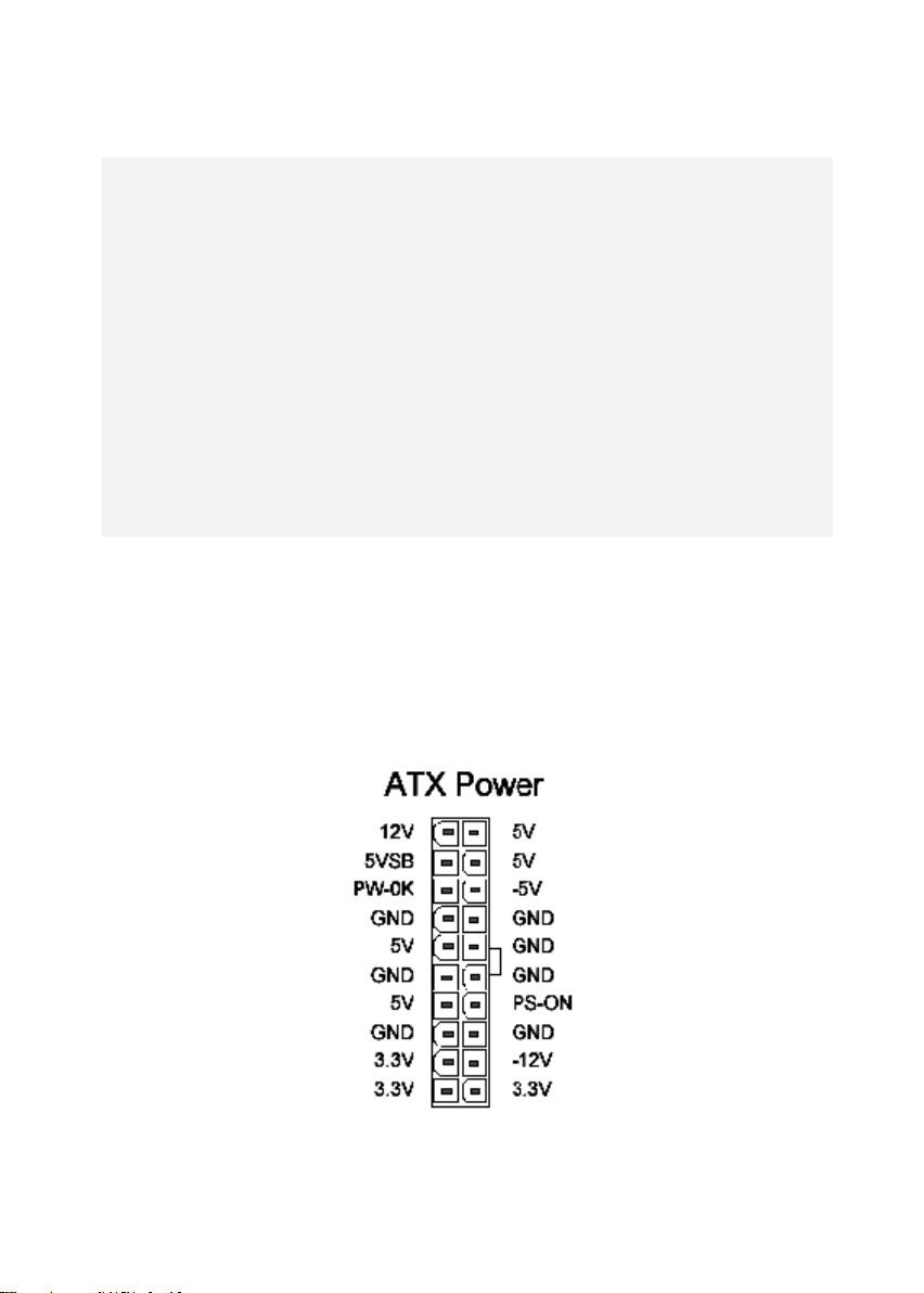
III-5-1 Power Supply Connector
Plug the connector from the power directly into the 20-pin male ATX PW
connector on the motherboard as shown in the following figure. The plug from the
power supply will only insert in one orientation because of the different hole sizes.
Find the proper orientation and push down firmly making sure that the pins are
aligned and the power supply is off before connecting or disconnecting the power
cable.
Page 18
III-5-2 Keyboard, Mouse, USB, COM Port and Printer port
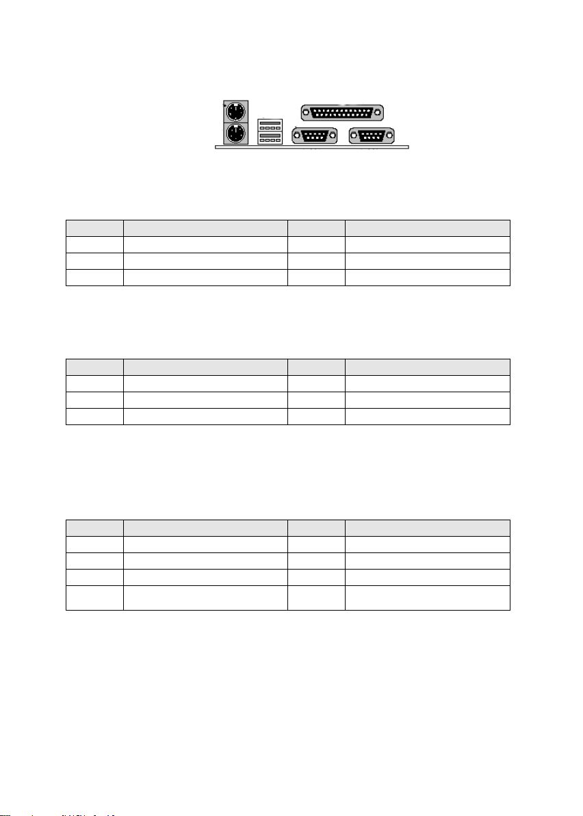
PS/2 Keyboard Connector
The onboard PS/2 keyboard connector is a 6-pin Mini-Din connector
marked KB2.The view angle of drawing shown here is from back panel
of the housing.
Pin Description Pin Description
1 Keyboard Data 2 N.C.
3 Ground 4 +5VDC
5 Keyboard Clock 6 N.C.
PS/2 Mouse Connector
The onboard PS/2 mouse connector is a 6-pin Mini-Din connector
marked PS2.The view angle of drawing shown here is from back
panel of the housing.
Pin Description Pin Description
1 Mouse Data 2 N.C.
3 Ground 4 +5VDC
5 Mouse CLK 6 N.C
USB (Universal Serial Bus Connector)
You can attach USB devices to the USB connector. The Mother board contains two
USB connectors, which are marked as USB. USB is a new serial bus design that is
capable of cascading low-/medium-speed peripherals (less than 12Mbps) such as
keyboard, mouse, joystick, scanner, printer and modem/ISDN. With USB, complex
cable connections at the back panel of your PC can be eliminated.
Pin Description Pin Description
1 +5 VDC 5 +5VDC
2 DATA - 6 DATA3 DATA + 7 DATA+
4 Ground 8 Ground
Serial Devices (COM1/COM2)
The onboard serial connectors are 9-pin D-type connector on the back
Panel of mainboard. The serial port 1 connector is marked as COM1 and
the serial port 2 connector is marked as COM2.
Printer Port ( LPT )
The onboard printer connector is a 25-pin D-type connector marked
PRINTER. The view angle of drawing shown here is from back panel of the
housing.
Page 19
III-5-3 Front Panel Connector
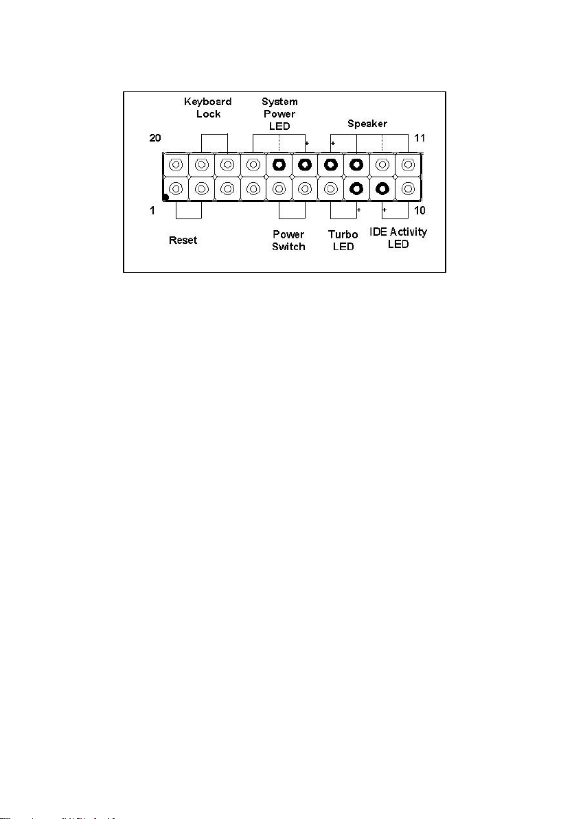
1). IDE Activity LED ( Pin 9,10)
This connector connects to the IDE (hard disk) activity indicator light on the
system abinet.
2). System Power LED ( Pin 15,16,17)
This 3-pin connector lights the system power LED when the motherboard
has power.
3). Turbo LED (Pin 7,8)
If the cabinet provide the turbo LED cable, connect the cable to this two pin
connector to turn on the LED on the front panel.
4). ATX Power Switch ( Pin 5,6 )
The system power is controlled by a push-switch, connected to this lead.
Pushing the button once will turn on the power and pushing again will turn
off the power. The system power LED shows that status of the system’s
power. If the power to the ATX power supply is interrupted while the
motherboard is on, standby power will remember that the motherboard
should be on and boot the computer when power is reapplied to the ATX
power supply.
5). Reset Switch ( Pin 1,2 )
This 2-pin connector connects to the case-mounted reset switch for
rebooting your computer without having to turn off your power switch. This
is a preferred method of rebooting in order to prolong the life of the
system’s power supply.
6). Keyboard Lock Switch Lead ( Pin 18,19 )
This 3-pin connector connects to the case-mounted keyboard lock switch
for locking the keyboard.
7). Speaker Connector ( Pin 11,12,13,14 )
This 4-pin connector connects to the case-mounted speaker.
Page 20
III-5-4 FAN Connector
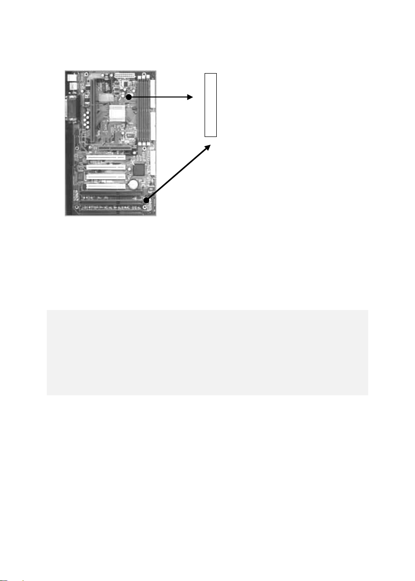
1).This connectors support a CPU cooling fan of 500 mA (6WATT, +12V) or
less. Orient the fan so that the heat sink fins allow airflow to go across the
onboard heat sink(s). Depending on the fan manufacturer, the wiring and
plug may be different. The red wire should be positive (+12V), while the
black should be ground. Connect the fan’s plug to the board taking into
consideration the polarity of the connector.
WARNING!
The CPU and/or motherboard will overheat if there is no airflow
across the CPU and onboard Heatsink. Damage may occur to the
motherboard and/or the CPU fan if these pins are incorrectly used.
These are not jumpers, do not place jumper caps over these pins.
Vcc ( FAN Speed Control )
Page 21
III-5-5 IrDA Compliant Infrared Module Connector
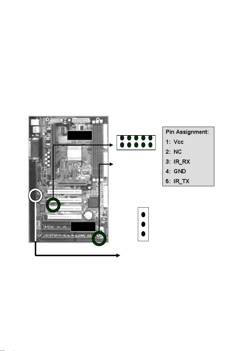
These connectors support the optional wireless transmitting and receiving
infrared module. This module mounts to a small opening on system cases
that support this feature. You must also configure UART 2. Use Infrared in
Chipset Features Setup to select whether UART 2 is directed for use with
COM2 or IrDA. When IrDA is selected in BIOS, COM2 will be disabled. Use
the five pins or six pins as shown and connect a ribbon cable from the
module to the motherboard to the pin definitions. There are two connectors
are available for the IrDA, one is near to Front Panel the other is rear, user
can use one of them to connect to IrDA module depending on the location
you want.
III-5-6 Wake-On-LAN (WOL)
Attach the 3-pin connector from the LAN card which supports the WakeOn-LAN (WOL) function to the WOL connector on the motherboard. This
WOL function lets users wake up the connected computer through the LAN
card. Please install according to the above pin assignment:
1 2 3 4 5
10 6
WOL ( Option )
Page 22
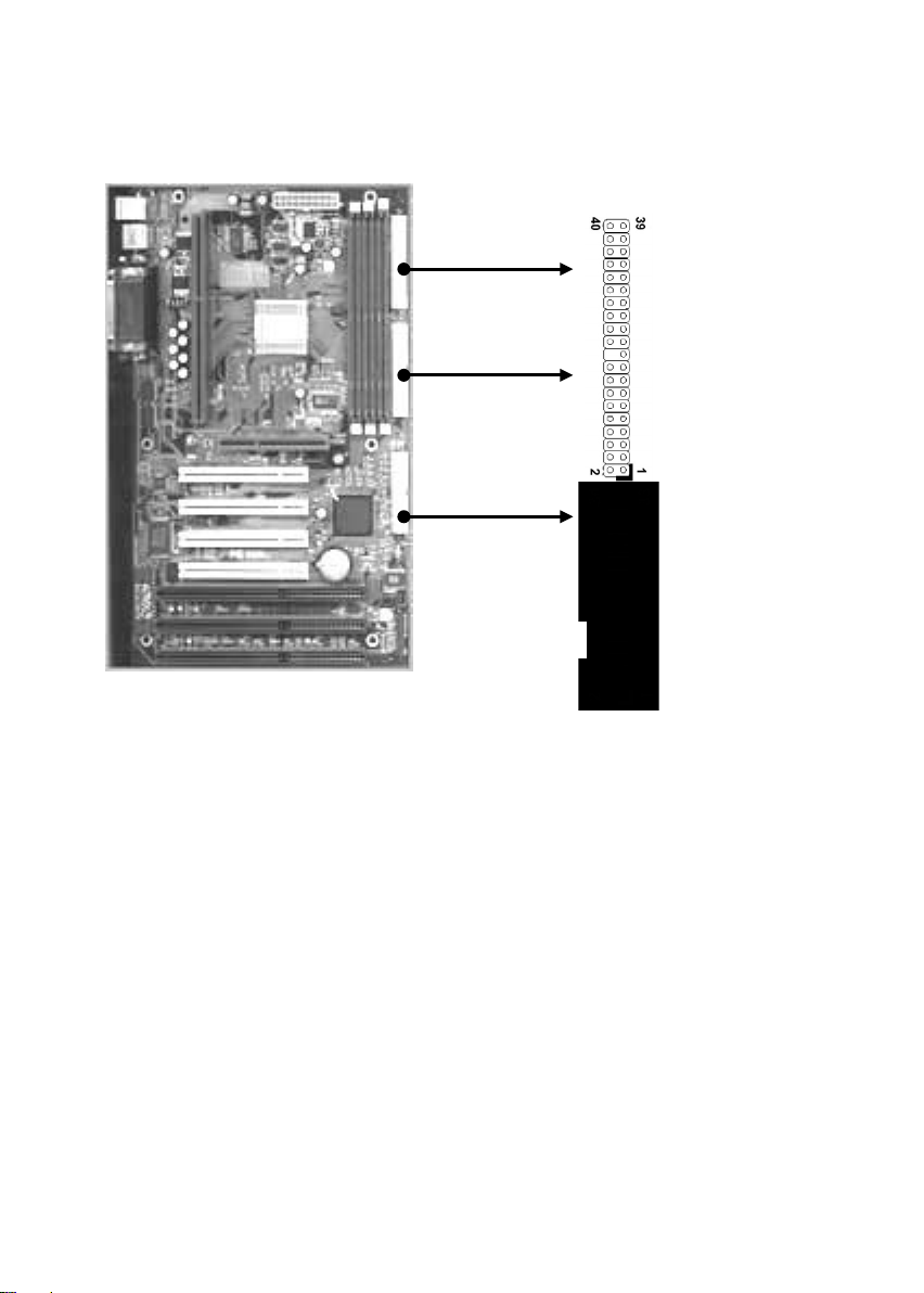
III-5-7 FDD & HDD Connector
IDE 1
FDD
IDE 2
Page 23

III-6 Power On Procedure:
1. After all connections are made, close the system case cover.
2. Be sure that all switches are off (in some systems, marked with ○).
3. Make sure your power supply voltage is correctly set to 110V or 230V.
4. Connect the power supply cord into the power supply located on the
back of your system case according to your system user's manual.
5. Connect the power cord into a power outlet that is equipped with a
surge protector.
6. You may then turn on your devices in the following order:
Your monitor
External SCSI devices (starting with the last device on the
chain)
Your system power. For ATX power supplies, you need to
switch on the power supply as well as press the ATX power
switch on the front of the case.
7. The power LED on the front panel of the system case will light. For
ATX power supplies, the system LED will light when the ATX
power switch is pressed. The monitor LED may light up after the
system power up. if it complies with "green" standards or if it has a
power standby feature. The system will then run power-on tests.
While the tests are running, additional messages will appear on the
screen. If you do not see anything within 30 seconds from the time
you turn on the power, the system may have failed a power-on
test. Recheck your jumper settings and connections or call your
retailer for assistance.
8. During power-on, hold down <Delete> to enter BIOS setup menu if
you want to run the BIOS Setup Utility.
Note:
Powering Off your computer: You must first exit or shut down your
operating system before switching off the power switch. For ATX
power supplies, you can press the ATX power switch after exiting or
shutting down your operating system. If you use Windows 95/98, click
the Start button, click Shut Down, and then click Shut down the
computer. The system will give three quick beeps after about 30
seconds and then power off after Windows shuts down.
Page 24
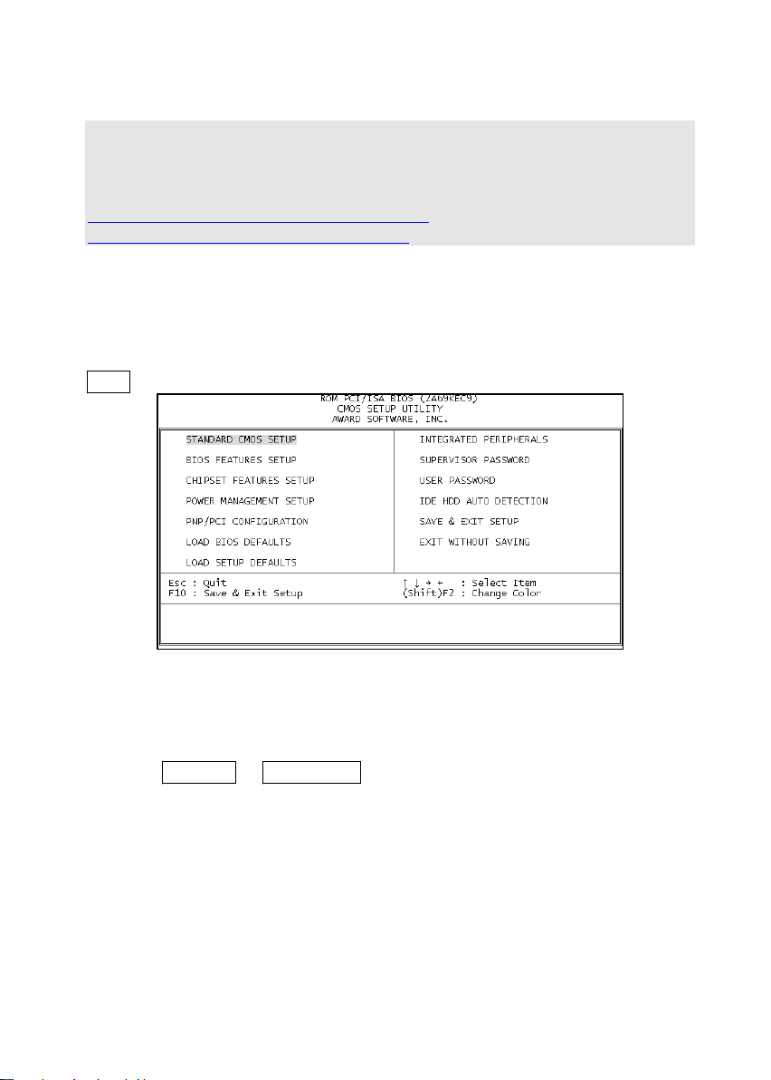
IV. BIOS SETUP TIPS
This charter only describes the major items that could be setup by End
User point of view. If you are technical people or familiar with the BIOS
setting or you have the interesting about the details of the BIOS setup,
please refer to the documents from Award by download following files.
http://www.enpc.com.tw/ftp/ts/setup451.zip
http://www.enpc.com.tw/ftp/ts/i440bx.zip
Entering the Award BIOS Setup Menu
The BIOS setup utility is a segment of codes/routines residing in the BIOS
Flash ROM. This routine allows you to configure the system parameters
and save the configuration into the 128 byte CMOS area, (normally in the
RTC chip or directly in the main chipset). To Enter the BIOS Setup, press
DEL during POST (Power-On Self Test).
Standard CMOS Setup
The "Standard CMOS Setup" sets the basic system parameters such as
the date, time, and the hard disk type. Use the arrow keys to highlight an
item and Page Up or Page Down to select the value for each item.
Tips:
The enhanced IDE feature allows the system to use a hard disk with a
capacity of more than 528MB. This is made possible through the Logical
Block Address (LBA) mode translation. The LBA is now to be considered as
a standard feature of current IDE hard disk on the market which capability
is larger than 528MB. Note that if HDD is formatted with LBA On, it will not
be able to boot with LBA Off.
Page 25
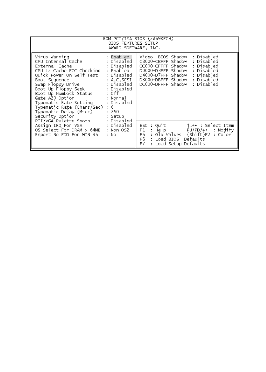
BIOS Features Setup
This screen appears when you select the option "BIOS Features Setup"
from the main menu. There are many items for the user to setup regarding
to the BIOS feature. Most of them are standard setting, basically, it is
recommended to set to default, the following item is the description for the
special function and setup tips:
Virus Warning
This feature protects the boot sector and partition table of your hard disk from virus
intrusion.
Quick Power On Self Test
Speeds up POST by skipping some items that are normally checked.
Boot Sequence
Allows you to specify the system boot up search sequence. For example, if you
want to boot up the system from CD-ROM, you can set the sequence here.
Boot Up NumLock Status
Setting this parameter to On enables the numeric function of the numeric keypad.
Gate A20 Option
Fast that mean GateA20 signal supported by core logic. Normal mean GateA20
signal supported by keyboard controller
Assign IRQ For VGA
This option allows BIOS to assign IRQ for VGA device
OS Select for DRAM > 64MB
Set to OS/2 if your system is utilizing an OS/2 operating system and has a memory
size of more than 64 MB.
Page 26
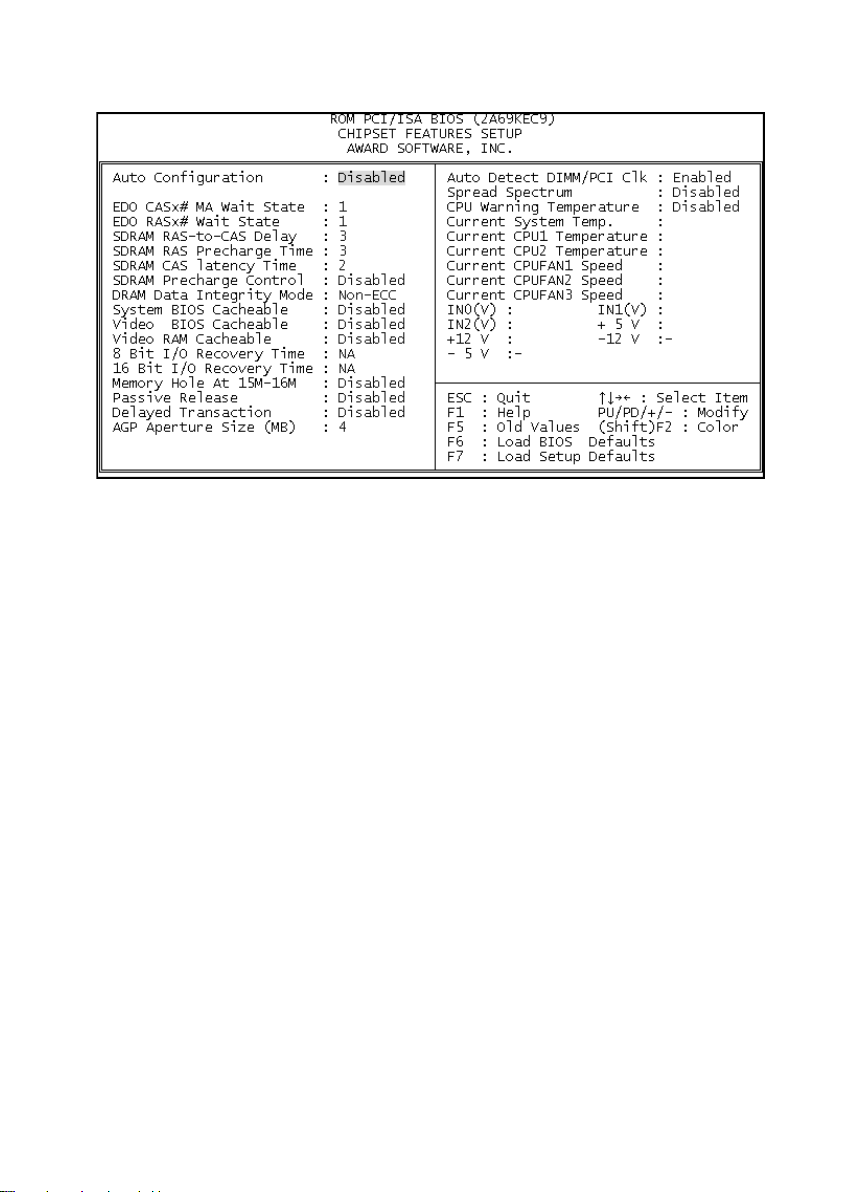
Chipset Features Setup
The "Chipset Features Setup" includes settings for the chipset dependent
features. These features are related to system performance. It is highly
recommended that the items are optimal setting for this Main-Board. You
should not change them unless you are familiar with the chipset. Make sure
you fully understand the items contained in this menu before you try to
change anything. You may change the parameter settings to improve
system’s performance. However, it may cause system unstable if the
settings are not correct for your system configuration. Once you change the
setting and not sure which one will be better parameter, please load the
BIOS default by press “F6” or load the SETUP default by press “F7”.
SDRAM RAS-to-CAS delay
They are important parameters that affect the SDRAM performance. If your SDRAM
has unstable problem, change 2/2 to 3/3.
SDRAM CAS Latency Time
This setting defines the CAS timing parameter of the SDRAM in terms of clocks.
Sometime, the BIOS will recommend you to set the correct value depending on the
DIMM Module you use.
Page 27
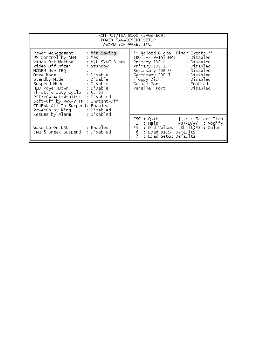
Power Management Setup
The Power Management Setup screen enables you to control the Main
Board green features.
Power Management
This function allows you to set the default parameters of power-saving modes.
PM Control by APM
If "Max Saving" is selected, you can turn on this item, transfer power
management control to APM
Video Off Method
The option "V/H SYNC+Blank" allows the BIOS to blank off screen display by
turning off the V-Sync signals sent from add-on VGA card. "DPMS Supported"
allows the BIOS to blank off screen display by your add-on VGA card which
supports DPMS; "Blank Screen" allows the BIOS to blank screen display by
turning off the red-green-blue signals.
Video Off After
What time frame that the video will be disabled under current power
management settings.
MODEM use IRQ
When the system is in green function, modem will wakes up the system through
IRQ you assigned here.
Doze Mode
When disabled, the system will not enter Doze mode. The specified time option
defines the idle time the system takes before it enters Doze mode.
Page 28

Standby Mode
When the standby mode timer times-out, it will enter the standby mode and
retain CPU at a slow working speed. The screen will be blanked out.
Suspend Mode
This function works only when the Pentium II Processor is installed. The timer
starts to count when system Standby mode timer is timed out and no PM
Events are occurring. Valid range is from 1 minute up to 1 hour.
HDD Power Down
This option lets you specify the IDE HDD idle time before the device enters the
power down state.
Throttle duty Cycle
Choose the duty cycle time : 12.5%, 25%, 37.5%, 50%, 62.5%(default), 75%, or
87.5%. The bigger of the percentage, the more saving power it gets.
PCI/VGA Active Monitor
Enabled : the system can not enter the power saving mode when monitor is on.
Disabled : the system can enter the power saving mode when monitor is on.
Soft-Off by PWRBTN
When enabled, turning the system off with the on/off button places the system
in a very low-power-usage state, with only enough circuitry receiving power to
detect power button activity or Resume by Ring activity.
Resume by Ring
Enabled : Wake up the system from ring signal.
Disabled : (default) Ring signal can not wake up the system.
Resume by Alarm:
his option allows you to have the system turn on at a preset time each day or
on a certain day.
IRQ8 Break Suspend
Choose Enabled or Disabled (default). Alarm function will be activated when
this function is enabled.
If the [ Resume by Ring ] set to Enable, that means the machine will
wake up after a external Modem Ring in through the COM Port. That is
the special function for the Modem Ring on. But if the machine is in the
off mode and you just power ON/OFF the external Modem, sometimes,
it will cause the machine power on, because the Modem Power
On/OFF pulse will be taken as the Modem Ring in signal and then
power up the machine.
Page 29

Page 30
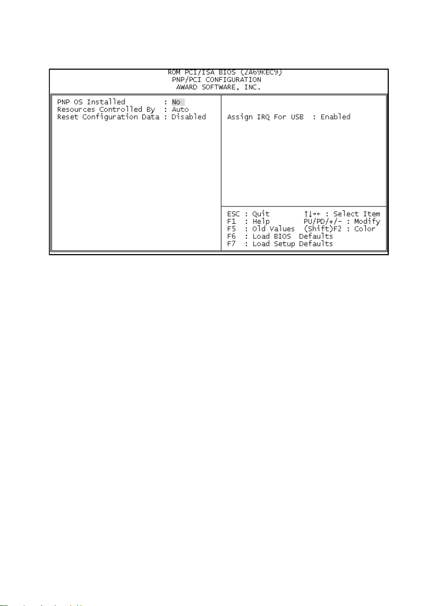
PNP/PCI Configuration
The PNP/PCI Configuration Setup allows you to configure the ISA and PCI
devices installed in your system.
PnP OS Installed
Normally, the PnP resources are allocated by BIOS during POST (Power-On Self
Test). If you are using a PnP operating system (such as Windows 95,98), set this
item to Yes to inform BIOS to configure only the resources needed for booting
(VGA/IDE or SCSI). The rest of system resources will be allocated by PnP
operating system.
Resources Controlled By
Setting this option to Manual allows you to individually assign the IRQs and DMAs
to the ISA and PCI devices. Set this to Auto to enable the auto-configuration
function.
Reset Configuration Data
If you had plugged some Legacy cards in the system and there were records into
ESCD (Extended System Configuration Data). You can set this field to Enabled to
clear ESCD one time, while the Legacy cards were removed.
Assign IRQ For USB
Assign IRQ For USB device
Page 31

LOAD BIOS / SETUP DEFAULTS
This Main Menu item loads the default system values. These settings are
recommended for optimum performance. If the CMOS is corrupted when
enter BIOS setup utility you must load setup default again. Choose this item
and the following message appears:
Load SETUP Defaults (Y/N)? Y
To use the Setup defaults, change the prompt to and press <Y> and press
<Enter>.
Note:
Optimal is not the slowest setting for this mainboard. If you need to
verify a unstable problem, you may manually set the parameter in the
"BIOS Features Setup" and "Chipset Features Setup" to get slowest
and safer setting.
Page 32
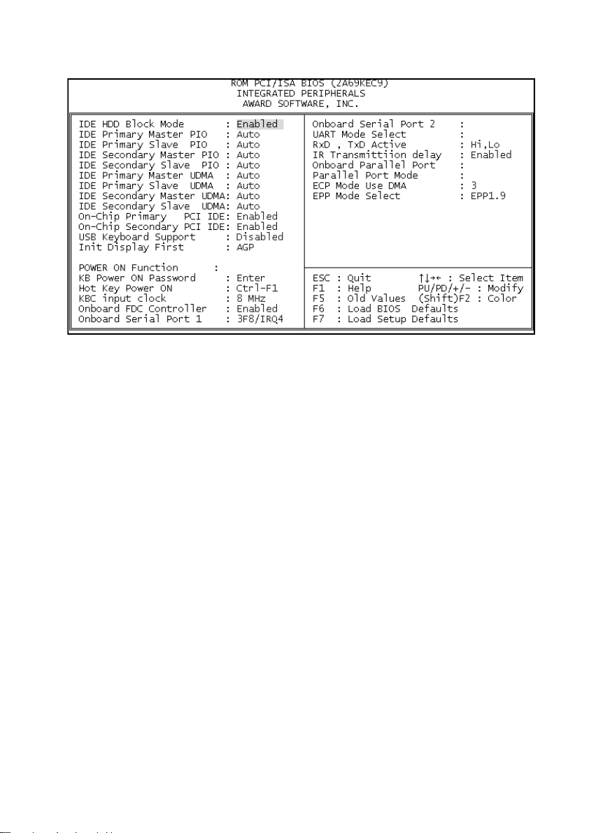
INTEGRATED PERIPHERALS SETUP
The INTEGRATED PERIPHERIALS is used to control the values of the I/O
chipset registers. These registers control the mode of HDD type and I/O
address port.
Note:
If you don't use the Onboard IDE connector, than use On-card (PCI or ISA
card ) IDE connector, you will set Onboard Primary PCI IDE : Disabled and
Onboard Secondary PCI IDE : Disabled from CHIPSET FEATURES
SETUP UTILITY. The Onboard PCI IDE cable should be equal to or less
than 18 inches (45cm).
IDE Secondary Master UDMA / IDE Secondary Slave UDMA
Allows you to select the second PCI IDE channel of the secondary master hard disk
mode or to detect it by the BIOS if the hard disk supports UDMA (Ultra DMA, faster
than DMA).
USB Keyboard Support
Choose Disabled (default) or Enabled. You need to use the regular keyboard to get
in the BIOS Setup to enable this function before using the USB keyboard.
Init Display First
Set the Display Card priority for the PCI slot or AGP Slot
Page 33

KB Power on Password
Set the keyboard power on password, if you enable this function, you can use the
keyboard to power on the machine with the password you defined, but at the
same time, the machine can’t be power on with the normal power button on the
front panel.
Hot key power on
Set the power on hot key, the function almost the same with the keyboard power on
function.
UART Mode Select
Choose Normal (default), IrDA 1.0, or ASKIR to meet the specification of your Infra
Red device.
RxD, TxD Active
Choose Hi/Hi; Hi/Lo (default); Lo/Hi; or Lo/Lo. Ask your IR provider when you use
this function.
IR Transmission Delay
Choose Enabled or Disabled. Ask your IR provider when you use this function.
USER Password
This Main Menu item lets you configure the system so that a password is
required every time the system boots or an attempt is made to enter the
Setup program. The password cannot be longer than 8 characters.
IDE HDD Auto Detection
If your system has an IDE hard drive, you can use this utility to detect its
parameters and automatically enter them into the Standard CMOS Setup.
Normal mode
For drivers small than 528MB
Large Mode
For drives larger than 528MB that do not use LBA. There can only be used
with MS-Dos operating system.
LBA mode
For drivers larger than 528MB and up to 8.4GB that use logic block
addressing mode. Normally we recommend to select LBA Mode if our HDD
drivers large than 528MB
SAVE & EXIT SETUP
Page 34

V. FAQ for this MotherBoard
1. The bios gives the error message "SPD not found on slot 3". It will
boot anyway but the error is still there and it makes end users
very worried.
Please read the following message from the Intel Web Site:
http://developer.intel.com/design/motherbd/se/SE_MEM.htm
All memory components and DIMMs used with the SE440BX motherboard should
comply with the PC SDRAM specifications. These include: the PC SDRAM
Specification (memory component specific), the PC Unbuffered DIMM
Specification, and the PC Serial Presence Detect Specification.
NOTE. It is recommended that SPD memory DIMMs be used with the SE440BX
motherboard. However, the BIOS will allow the use of non-SPD DIMM memory ”
That mean your DIMM module is not support SPD specification, but it is
OK, it just a warning message and doesn’t impact the PC working.
2. Celeron 300A CPU does not ID correctly and does not function
correctly on this motherboards.
Please update the BIOS to V1.6 from the Web Site:
http://www.enpc.com.tw/ftp/bios/Kb2116.bin
3. Can’t have the sound output with the Creative PCI 128 Sound Card
and this Mother Board.
Please try to change one resistor, R176 located between ISA1 and ISA 2 and near
the FAN1 connector, from 4.7k to 1k ohm. For this Old Version Mother Board. Rom
the Version 1.4 of the M/B, the problem had been solved.
4. I have an Intel 300-Mhz Pentium II CPU, I am pretty sure the bus
clock should be set to 66-Mhz and the ratio set to 4.5. Is that
correct or can I run this at 100-Mhz bus with ratio at 3 ?
Yes! the M/B support 100Mhz clock, you can select 100MHZ x 3 for the PII
300 MHZ CPU, and also please make sure the DIMM can support PC-100
specification. That mean if you use the 100Mhz, it is highly recommended
that use the -8 or -7 DIMM Module instead of -10 or -12 DIMM module.
The Intel have two kinds of the P II 300 MHZ CPU, you also need to double
check the CPU, is it a Klamath type or Dechute? The first one supports only
66 MHZ front side bus, the other one support real PC-100 Spec. That’s why
there are two selection for 300Mhz ( 66 x 4.5 and 100 x 3 ).
Page 35

VI. Year 2000 (Y2K) Compliant
Dear Sirs,
The following is the Year 2000 (Y2K) Compliant Test Report for the Model
KB21:
Uses the test program released by NSTL to ensure the product are Year
2000 compliant both in hardware and BIOS. The testing procedure is as
below:
Run the program Y2000.EXE released by NSTL for the compliance test:
1. Verify MC146818 RTC compatibility. This test ensures that the date and
time indices are compatible to the MC146818 and the data is in packed
BCD format. Some non-DOS based operating systems, like Unix, do not
use the BIOS but use drivers to access the clock directly. This test
ensures that the clock is a Motorola MC146818 compatible chip. If the
chip is not compatible, then these "other" operating systems or programs
that read the clock directly may fail.
2. Verify real-time progression from December 31st, 1999 to January 1st,
2000. If real-time support fails, then the ability to set the date manually is
checked.
3. Verify recognition and support of leap years from 2000 through 2009.
Detail BIOS Version : KB21 ROM BIOS Ver. 1.6 09/04/1998
Test Result: : PASS
 Loading...