

Page 1

1
Page 2

Table of Contents
Chapter 1 Product Overview .................................................................................................................................................... 6
Key Features ............................................................................................................................................................................................ 7
Introduction .............................................................................................................................................................................................. 8
System Requirements ............................................................................................................................................................................... 9
Package Contents ..................................................................................................................................................................................... 9
Applications ........................................................................................................................................................................................... 10
Technical Specifications .........................................................................................................................................................................11
Physical Interface ................................................................................................................................................................................... 12
Chapter 2 Before You Begin ................................................................................................................................................... 14
Considerations for Wireless Installation ................................................................................................................................................ 15
Computer Settings .................................................................................................................................................................................. 16
Hardware Installation ............................................................................................................................................................................. 20
Mounting the Access Point .................................................................................................................................................................... 21
Chapter 3 Configuring Your Access Point ............................................................................................................................. 24
Default Settings ...................................................................................................................................................................................... 25
Web Configuration ................................................................................................................................................................................. 26
Chapter 4 User Interface ......................................................................................................................................................... 30
Navigation Panel..................................................................................................................................................................................... 31
Live View Management .......................................................................................................................................................................... 33
Chapter 5 Access Point Settings ............................................................................................................................................ 36
Device Status .......................................................................................................................................................................................... 37
Connections ............................................................................................................................................................................................ 40
Realtime ................................................................................................................................................................................................. 41
Chapter 6 Network ................................................................................................................................................................... 43
IPv4 Settings .......................................................................................................................................................................................... 44
2
Page 3

Spanning Tree Settings........................................................................................................................................................................... 45
Chapter 7 Wireless ................................................................................................................................................................... 46
System Properties ................................................................................................................................................................................... 47
Operation mode ...................................................................................................................................................................................... 48
2.4GHz/5GHz SSID Profile ................................................................................................................................................................... 51
Wireless Security ................................................................................................................................................................................... 53
Wireless MAC Filter .............................................................................................................................................................................. 56
Traffic Shaping ....................................................................................................................................................................................... 57
Fast Roaming ......................................................................................................................................................................................... 58
WDS Link Settings ................................................................................................................................................................................ 59
Guest Network ....................................................................................................................................................................................... 61
RSSI Threshold ...................................................................................................................................................................................... 63
Management VLAN Settings ................................................................................................................................................................. 64
Chapter 8 DDNS ........................................................................................................................................................................ 65
Chapter 9 UPnP ........................................................................................................................................................................ 68
Chapter 10 Service Port .......................................................................................................................................................... 70
Chapter 11 Mesh ...................................................................................................................................................................... 72
Status ...................................................................................................................................................................................................... 73
Settings ................................................................................................................................................................................................... 74
Tools ....................................................................................................................................................................................................... 75
Node List ................................................................................................................................................................................................ 75
Link Status ............................................................................................................................................................................................. 77
Ping ........................................................................................................................................................................................................ 77
Trace Route ............................................................................................................................................................................................ 78
Throughput ............................................................................................................................................................................................. 78
Chapter 12 Management ......................................................................................................................................................... 79
Controller Settings ................................................................................................................................................................................. 80
3
Page 4

SNMP Settings ....................................................................................................................................................................................... 80
CLI/SSH Settings ................................................................................................................................................................................... 83
HTTPS Settings...................................................................................................................................................................................... 84
Email Alert ............................................................................................................................................................................................. 85
Date and Time Settings .......................................................................................................................................................................... 86
WiFi Scheduler ....................................................................................................................................................................................... 87
Tools ....................................................................................................................................................................................................... 89
LED Control ........................................................................................................................................................................................... 93
Device Discovery ................................................................................................................................................................................... 94
Chapter 13 System Manager .................................................................................................................................................. 95
Account Setting ...................................................................................................................................................................................... 96
Firmware Upgrade ................................................................................................................................................................................. 98
Backup/Restore ...................................................................................................................................................................................... 99
Reset/Reboot ........................................................................................................................................................................................ 101
System Log .......................................................................................................................................................................................... 101
Chapter 14 Camera OverView ............................................................................................................................................. 103
Camera Status ...................................................................................................................................................................................... 104
PC Storage Path ................................................................................................................................................................................... 105
Chapter 15 Media .................................................................................................................................................................. 106
Video .................................................................................................................................................................................................... 107
Camera ................................................................................................................................................................................................. 108
Advance ................................................................................................................................................................................................115
Privacy Mask.........................................................................................................................................................................................117
Audio .....................................................................................................................................................................................................118
Chapter 16 Event Management .......................................................................................................................................... 119
Event Control ....................................................................................................................................................................................... 120
Motion Detection ................................................................................................................................................................................. 123
4
Page 5

Audio Detection ................................................................................................................................................................................... 126
Tampering Detection ............................................................................................................................................................................ 127
Event Action ......................................................................................................................................................................................... 128
Chapter 17 Event Server ...................................................................................................................................................... 130
Network Storage .................................................................................................................................................................................. 131
FTP(File Transfer Protocol) ................................................................................................................................................................. 134
E-Mail .................................................................................................................................................................................................. 135
Chapter 17 Storage Info ....................................................................................................................................................... 136
Storage Info .......................................................................................................................................................................................... 137
Appendix ................................................................................................................................................................................... 139
Appendix A - FCC Interference Statement .......................................................................................................................................... 140
Appendix B - CE Interference Statement............................................................................................................................................. 142
5
Page 6

Chapter 1
Product Overview
6
Page 7

Introduction
Key Features
Deploy and manage with ease using EWS Series Wireless Management Switches.
Advance Access Point mode with mesh network support.
Dual Concurrent 2.4GHz and 5GHz architecture with max transfer rates of up to 300+867 Mbps.
Internal 5dBi Omni-Directional MIMO antennas optimized for maximum RF performance.
Backward compatible with IEEE802.11a/b/g/n wireless devices.
Integrated Power over Ethernet (IEEE802.3af) for lowering deploying costs. Can be powered using either the included power
adapter or via PoE with PoE 802.3af capable Switches or Injectors.
Band Steering to load balance clients between 2.4GHz and 5 GHz for better throughput performance.
Secure Guest Network option available.
Stylish low profile design with easy ceiling mounting kit.
Full HD Sony CMOS image sensor delivers 30fps in 1080P resolution.
Provide true day/night functionality with 20 meter IR LEDs illuminator and IR cut filter.
H.264 high compression video with VLAN and prioritizing QoS for delivering easily.
EnGenius DDNS, P2P and Push Notification.
Free iOS & Android APP for view / record.
Free bundle Video Management Software.
ONVIF compatible (Profile S).
7
Page 8

Introduction
EnGenius Indoor Mesh Access Point Camera is a new concept of dual band concurrent, high power, high sensitivity and strong reliability
for enterprise solutions. Easy setup and installation for combination of two products – Access point and IP camera, one PoE or DC power
solve the power input, and single UI interface for all configurations. To integrate the hotspot service and surveillance, EWS1025CAM not
only wireless mesh access point extends wireless access over large, metro scale areas, eliminates costly Ethernet cabling to every Wi-Fi
access point, but also provides high resolution video streaming for security. It can be easily deployed and maintained with no
configuration deployment and recovery capacity. Extended signal range from high-gain antenna arrays reduce the number of mesh
nodes typically required. The EWS1025CAM is a component of the EWS Neutron Series Switches, delivering a robust wireless network
with maximum capacity and uptime, the wireless mesh can be seamlessly deployed as an extension of wired and wireless networks,
with central management through controllers. No IT experts required for installation, system automatically determines the optimal
network topology and maintains the best connections between mesh nodes. The centralize functions of the wireless LAN to provide
scalable management, advanced security, seamless mobility, and proven reliability.
This device is an enhanced-powered, long-range wireless access point. It is designed to operate in numerous environments; from large
homes, small and medium-sized businesses, multiple-floor offices, hotels, and other venues, to larger enterprise deployments. Its
enhanced-powered, long-range characteristics make it a cost-effective alternative to ordinary Access Points that don’t have the range
and reach to connect to a growing number of wireless users who wish to connect to a large hotspot or business network.
To protect sensitive data during wireless transmissions, the device offers different encryption settings for wireless transmissions,
including industry standard WPA and WPA2 encryption. The device also includes MAC address filtering to allow network
administrators to offer network access only to known computers and other devices based on their MAC addresses.
8
Page 9

System Requirements
The following are the Minimum System Requirements in order to configure the device:
Computer with an Ethernet interface or wireless network capability
Windows OS (XP, Vista, 7, 10), Mac OS, or Linux-based operating systems
Web-Browsing Application (i.e. : Internet Explorer, Firefox, Safari, or another similar browser application)
Package Contents
The package contains the following items (all items must be in package to issue a refund):
EWS1025CAM Managed Indoor Mesh Camera
Power Adapter
RJ-45 Ethernet Cable
Quick Installation Guide
Mounting Bracket
Mount Screw kit
9
Page 10

Applications
Wireless LAN (WLAN) products are easy to install and highly efficient. The following list describes some of the many applications
made possible through the power and flexibility of WLANs:
Difficult-to-Wire Environments: There are many situations where wires cannot be installed, deployed easily, or cannot be
hidden from view. Older buildings, sites with multiple buildings, and/or areas that make the installation of a Ethernet-based
LAN impossible, impractical or expensive are sites where WLAN can be a network solution.
Temporary Workgroups: Create temporary workgroups/networks in more open areas within a building; auditoriums,
amphitheaters classrooms, ballrooms, arenas, exhibition centers, or temporary offices where one wants either a permanent or
temporary Wireless LAN established.
The Ability to Access Real-Time Information: Doctors/Nurses, Point-of-Sale Employees, and/or Warehouse Workers can access
real-time information while dealing with patients, serving customers, and/or processing information.
Frequently Changing Environments: Set up networks in environments that change frequently (i.e.: Show Rooms, Exhibits, etc.).
Small Office and Home Office (SOHO) Networks: SOHO users require a cost-effective, easy, and quick installation of a small
network.
Training/Educational Facilities: Training sites at corporations or students at universities use wireless connectivity to exchange
information between peers and easily access information for learning purposes.
10
Page 11

Technical Specifications
EWS1025CAM
Standard
2.4GHz
IEEE802.11b/g/n
5GHz
IEEE802.11a/n/ac
Antennas
4 x Internal 5dBi Omni-Directional
Image Sensor
Sony 2Megapixel 1920 x1080 Progressive Scan COMS sensor
Lens
Fixed Board Lens, f =2.8mm/F2.0, F.O.V=120 Degree(Diagonal)
IR illuminator
20 Meter Range
Interface
1 x 10/100/1000 Gigabit Ethernet Port
1 x Reset Button
1 x Power Connector
1 x Micro SDXC card slot
LED Indicator
5GHz, 2.4GHz, Power, LAN, Mesh
PoE Support
IEEE802.3af
Power Requirement
External Power Adapter
DC IN, 12V/1.5A
Environment
Operating:
Temperature: 32°F to 122°F (0°C to 40°C)
Humidity (Non-condensing): 90% or less
Storage:
Temperature: -4°F to 140°F (-20°C to 60°C)
Humidity (Non-condensing): 90% or less
Dimensions
5.24 x 3.82 in./134 x 97mm
Weight
1.05lbs/478g
11
Page 12

Physical Interface
1
2 3 4 5 6 9 7
8
1. LAN Port (802.3af PoE): Ethernet port for RJ-45 cable.
2. Power Connector: 12V DC IN for Power Adapter.
3. Ceiling Mount Hole: Using the provided mounting kit, the Access Point can be attached to a ceiling or wall.
4. Micro SD card slot: Supported SDXC card for local storage.
5. Reset Button: Press and hold for over 10 seconds to reset to factory default settings.
6. LED Indicators: LED lights for Mesh, WLAN 5GHz, WLAN 2.4GHz, LAN, and Power.
7. Lens: 2 Megapixel wind angle fixed board lens.
8. Built-in Microphone: One way audio for recording.
12
Page 13

9. IR illuminator: 20 meter infrared for low lux environment.
13
Page 14

Chapter 2
Before You Begin
14
Page 15

Before You Begin
This section will guide you through the installation process. Placement of the EnGenius Access Point is essential to maximize the
Access Point’s performance. Avoid placing the Access Point in an enclosed space such as a closet, cabinet, or stairwell.
Considerations for Wireless Installation
The operating distance of all wireless devices can often not be pre-determined due to a number of unknown obstacles in
the environment in which the device is deployed. Obstacles such as the number, thickness, and location of walls, ceilings,
or other objects that the Access Point’s wireless signals must pass through can weaken the signal. Here are some key
guidelines for allowing the Access Point to have an optimal wireless range during setup.
Keep the number of walls and/or ceilings between the Access Point and other network devices to a minimum. Each wall and/or
ceiling can reduce the signal strength, resulting in a lower overall signal strength.
Building materials make a difference. A solid metal door and/or aluminum stubs may have a significant negative effect on the
signal strength of the Access Point. Locate your wireless devices carefully so the signal can pass through drywall and/or open
doorways. Materials such as glass, steel, metal, concrete, water (example: fish tanks), mirrors, file cabinets, and/or brick can
also diminish wireless signal strength.
Interference from your other electrical devices and/or appliances that generate RF noise can also diminish the Access Point’s
signal strength. The most common types of devices are microwaves or cordless phones.
15
Page 16

Computer Settings
Windows XP/Windows 7
In order to use the Access Point, you must first configure the TCP/IPv4 connection of your Windows OS computer system.
1. Click the
2a. In
Windows XP
button and open the
Start
Windows XP Windows 7
, click on Network Connections.
Control Panel
.
16
Page 17

2b. In
Windows 7
settings.
3. Right click on
, click
View network status and tasks
Local Area Connection
and select
Properties
in the
.
Network and Internet
section, then select
Change adapter
4. Select
Internet Protocol Version 4 (TCP/IPv4)
and then select
Properties
17
.
Page 18

5. Select
Use the following IP address
and enter an IP address that is different from the
Access Point and Subnet mask, then click OK.
: Ensure that the IP address and Subnet mask are on the same subnet as the
Note
device.
For example: EWS1025CAM IP address: 192.168.1.1
PC IP address: 192.168.1.2 – 192.168.1.255
PC Subnet mask: 255.255.255.0
18
Page 19

Apple Mac OS X
1. Go to
2. Select
System Preferences
Network
3. Highlight
4. In
Configure IPv4
in the
Ethernet
(it can be opened in the
Internet & Network
.
, select
Manually
Applications
folder or by selecting it in the Apple Menu).
section.
.
5. Enter an IP address that is different from the Access Point and
Subnet mask, then click OK.
Note: Ensure that the IP address and Subnet mask are on the same
subnet as the device.
For example: EWS1025CAM IP address: 192.168.1.1
PC IP address: 192.168.1.2 – 192.168.1.255
PC Subnet mask: 255.255.255.0
6. Click
Apply
when finished.
19
Page 20

Hardware Installation
1. Ensure that the computer in use has an Ethernet Controller port (RJ-45 Ethernet Port). For more information, verify with your
computer’s user manual.
2. Connect one end of the Category 5e Ethernet cable into the RJ-45 port of the Access Point and the other end to the RJ-45
port of the computer. Ensure that the cable is securely connected to both the Access Point and the computer.
3. Connect the Power Adapter DC connector to the DC-IN port of the Access Point and the Power Adapter to an available
electrical outlet. Once both connections are secure, verify the following:
a) Ensure that the
b) Ensure that the 2.4 GHz/5 GHz WLAN light is on (it will be
c) Ensure that the LAN (Computer/ Access Point Connection) light is on (it will be
d) Once all three lights are on, proceed to set up the Access Point using the computer.
POWER
light is on (it will be
orange
).
for 2.4G, and
blue
green
blue
for 5G).
).
20
Page 21

Mounting the Access Point
Using the provided hardware, the Access Point can be attached to a ceiling or wall.
To attach the Access Point to a ceiling or wall using the mounting bracket:
1. Attach the mounting bracket to the wall or ceiling using the provided wall/ceiling mounting hardware kit.
2. Insert the provided short screws into the bottom cover of the Access Point.
Leave enough of the screws exposed to ensure that the unit can be attached to the mounting bracket.
If extra space is required, use the provided spacers and long screws from the T-Rail mounting hardware kit to increase the space
between the unit and the mounting bracket.
21
Page 22

3. Mount the Access Point on the mounting bracket by rotating the unit clockwise about 90 degrees to secure it in place.
Attaching the Access Point to a ceiling using the provided T-Rail connectors:
1. Attach the T-Rail connectors to the bottom cover of the Access Point using the provided short screws.
Note:
space is required to accommodate drop ceiling tiles, use the provided spacers and long screws.
Two sizes of T-Rail connectors are included in the mounting hardware kit: 15/16in (2.38cm) and 9/16in (1.43cm). If extra
2. Line up the connected T-Rail connectors with an appropriately sized rail and press the unit onto the rail until it snaps into
place.
22
Page 23

23
Page 24

Chapter 3
Configuring Your
Access Point
24
Page 25

Configuring Your Access Point
IP Address
192.168.1.1/192.168.1.1200
Username/Password
admin/admin
This section will show you how to configure the device using the web-based configuration interface.
Default Settings
Please use your Ethernet port or wireless network adapter to connect the Access Point.
25
Page 26

Web Configuration
1. Open a web browser (Internet Explorer/Firefox/Safari) and enter the IP Address http://192.168.1.1.
: If you have changed the default LAN IP Address of the Access Point, ensure you enter the correct IP Address.
Note
2. The default username and password are:
admin
. Once you have entered the correct username and password, click the
Login
button to open the web-based configuration page.
3. For the first time of login, you will be informed to download and install “WebCMS”. Please click on “Download WebCMS“ to start
download (you will be required to have Internet connection on your router). WebCMS enables browsers to support camera
feature. Don’t worry if you are prompted with a different version number because the software upgrades from time to time.
26
Page 27
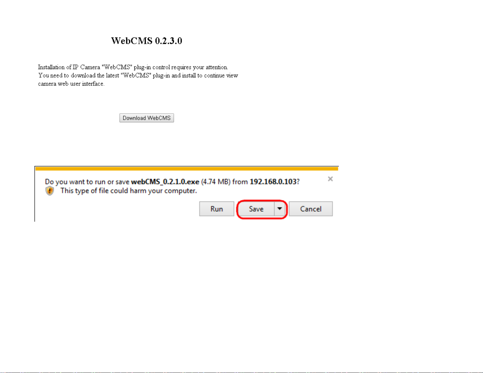
If prompted with the following question, click on Save (
the downloaded file.
Save
Internet Explorer
).
27
Page 28

Once download is completed, you MUST close all the browsers before install WebCMS.
Double click on
seconds for
WebCMS
WebCMS
to install the program. You may not have noticed, the installation is very fast, it only takes a few
to be installed.
When installation is completed, open the browser and login into the camera again. You should be able to see the camera
viewer in live as shown below. If you do not see the viewer that means you did not install WebCMS properly or try login using
other browsers.
28
Page 29

NOTE
: If you are seeing grey color in the viewer, it is because the camera has detected insufficient of light in the room and
enabled night vision mode automatically. If you point your camera to a brighter area, you should be able to see it switched to
normal color mode. Try a few places to get a feeling on how it works. If listening closely, you may hear the click sound from the
camera when night vision is switched on and off.
4. If successful, you will be logged in and see the Access Point User Interface.
29
Page 30

Chapter 4
User Interface
30
Page 31

User Interface
The
User Interface
• Navigation Panel
• Live View Management
The following sections describe these options.
section contains the following options:
Navigation Panel
31
Page 32

The
Navigate to home page for device information and connection status
Navigate to Reboot/Reset device page
Navigate to camera live view page
Navigate to the main setting page
Navigate to the Mesh tools page
Logout
Navigation Panel
is located at the top-right corner of the page.
The descriptions are as follows:
32
Page 33

Live View Management
There are two streams running concurrently: Stream1 (1920x1080) and Stream2 (640x360).
Stream1 has the higher resolution than stream2. Stream2 serves lower resolution for mobile devices
which has smaller screens. You can preview each stream at real time by selecting it from the list.
This opens the local folder where the real time captured images and clips are stored. You may
change the folder path at Main Menu System PC Storage Path
The
Live View Management
menu is located at the right side of the page.
33
Page 34

This switch only applies to resolution 640 x 360. When enabled, the preview image will switched to
1:1 mode. By default the image will expand and fill the view screen if the actual image is smaller
than the view.
This switch will hide the browser and expand the view to full screen. You can press ESC button to
cancel the full screen mode.
ePTZ display the digital zoom in for the region of interest, use your mouse to move the green
window at the left bottom to the area you intend to monitor.
34
Page 35

This button takes a snap-shot on the real time view and store the image in the local folder.
Toggle this button to start recording movie clip at real time. Click on the button to start recording.
Please note that when icon changed to blue icon the camera is recording. To stop
recording, simply click the button again.
Toggle this button to turn PC audio from the camera ON and OFF. The default is ON, click the
button to turn it ON; the icon should change to to signify OFF state.
35
Page 36

Chapter 5
Access Point Settings
36
Page 37

Overview
The
Overview
• Device Status
• Connections
• Real Time
The following sections describe these options.
section contains the following options:
Device Status
Clicking the
• The
Version, and Management VLAN ID
Device Status
Device Information
link under the
section shows general system information such as Device Name, MAC address, Current Time, Firmware
Overview
menu shows the status information about the current operating mode.
37
Page 38

• The
Memory Information
section shows system memory information such as used and Total available, Free, Cached and
Buffered
The
LAN Information
section shows the Local Area Network settings such as the LAN IP Address, Subnet mask, Gateway,
DNS Address, DHCP Client, and STP status.
The
Wirelesss LAN Information 2.4 GHz/5GHz
section shows wireless information such as Operating Mode, Frequency, and
Channel. Since the Access Point supports multiple-SSIDs, information about each SSID and security settings are displayed.
38
Page 39

39
Page 40

The
UID/DDNS
section shows each device is distributed with an exclusive unique identification (UID)/DDNS. You can find
the default UID/DDNS shown here.
Connections
Clicking the
Connections
link under the
Overview
menu displays the list of clients associated to the Access Point’s
2.4GHz/5GHz, along with the MAC address, TX, RX and signal strength for each client. Clicking
this client.
Click
Refresh
to refresh the Connection List page.
in the Block column removes
Kick
40
Page 41

Realtime
Clicking the
Realtime
link under the
Overview
menu displays CPU load, Traffic and Connections
CPU Load:
3 minutes CPU loading percentage information, it displays current loading, average loading and peak loading status. Left bar is
loading percentage; button is time tracing. Interval is every 3 seconds.
Realtime Traffic (kb/s):
2.4GHz and 5GHz and Ethernet port inbound and outbound traffic by current, average and peak time.
41
Page 42

Realtime Connection (Pkts):
Overview on current active network connections. It displays UDP and TCP packets information and other connection status. UDP
connections curve is in blue; TCP connection curve is in green; others curve is in red. Below of chart shows connections source
and destination.
42
Page 43

Chapter 6
Network
43
Page 44

Basic
This page allows you to modify the device’s IP settings and the Spanning Tree settings. Enabling Spanning Tree protocol will
prevent network loops in your LAN network.
IPv4 Settings
IP Network Setting
obtained automatically when the device connects to a DHCP server.
IP Address
IP Subnet Mask
Gateway
Primary/Secondary DNS
: The IP Address of this device.
: The Default Gateway of this device. Leave it blank if you are unsure of this setting.
: Select whether the device IP address will use the static IP address specified in the IP Address field or be
: The IP Subnet mask of this device.
: The primary/secondary DNS address for this device.
44
Page 45

Spanning Tree Settings
Status
Hello Time
communicate information about the topology throughout the entire Bridged Local Area Network.
Max Age
of time, it is assumed to be inactive.
Forward Delay
Learning states before the Forwarding state is entered. This delay is provided so that when a new bridge comes onto a busy
network, it analyzes data traffic before participating.
Priority
Apply
: Enables or disables the Spanning Tree function.
: Specify Bridge Hello Time, in seconds. This value determines how often the device sends handshake packets to
: Specify Bridge Max Age, in seconds. If another bridge in the spanning tree does not send a hello packet for a long period
: Specifies Bridge Forward Delay, in seconds. Forwarding Delay Time is the time spent in each of the Listening and
: Specify the Priority Number. A smaller number has greater priority.
: Click Apply to save the changes.
45
Page 46

Chapter 7
Wireless
46
Page 47

System Properties
Note: When enable band steering function, both 2.4GHz and 5GHz SSID and security setting must be the same.
Device Name
: Enter a name for the device. The name you type appears in SNMP management. This name is not the SSID and is not
broadcast to other devices.
Region
Band Steering
: Select Region to conform to local regulations.
: Send 802.11n client to the 5GHz band, where 802.11b/g clients cannot go and leave 802.11b/g clients in 2.4GHz
to operate their slower rate. Band Steering works within the Access Point by directing 5GHz-capable clients to the band.
EnGenius Band Steering supports following advanced settings,
*Prefer 5GHz: When band steering is configured to Prefer 5GHz mode, the AP will steer dual band capable client devices to 5GHz
radio when the RSSI value of these client devices on 5GHz radio is more than set one. The allowed RSSI value for default setting is
-75dBm.
*Force 5GHz: When band steering is configured to Force 5GHz mode, the AP will not dual band capable client devices to network to
the 2.4GHz band only if the client devices are not currently associated on 2.4GHz radio in this AP.
*Band Balance: When band steering is configured to Band Balance mode, the AP will steer dual band capable client devices to 5GHz
when the RSSI value of these client devices on 5GHz radio is more than set one. To evenly allocate RF resource on the both 2.4GHz
and 5GHz radios, users also can set the portion of client devices on 5GHz radio to assure smoothly connection. The default value of
the 5GHz radio is 75%.
Save: Click Save to confirm the changes.
47
Page 48

Operation mode
2.4GHz
5GHz
Access Point
Client Bridge
WDS AP
WDS Bridge
WDS Station
Access Point
● ● ● ● ●
Client Bridge
● X ● X X
WDS AP
● ● ● ● ●
WDS Bridge
● X ● X X
WDS Station
● X ● X X
The EWS1025CAM supports five operating modes:Access Point, Client Bridge, WDS AP, WDS Bridge, and WDS Station.
This page displays the current status of the Wireless settings of the EWS1025CAM.
48
Page 49

2.4G/5G Wireless Network (Access Point / WDS AP mode)
Wireless Mode
Wireless mode supports 802.11b/g/n mixed mode in 2.4G and 802.11ac/a/n mixed mode
in 5G.
Channel HT Mode
Scroll down this list to select bandwidth for operating under a frequency band. The default
channel bandwidth is 20 MHz on 2.4GHz frequency radio and 40 MHz on 5GHz frequency
radio. Considering the different applications, users can decide to implement a channel
bandwidth to fulfill real applications. The larger the channel, the greater the transmission
quality and speed.
49
Page 50

Channel / Frequency
Select the channel and frequency appropriate.
Auto
Check this option to enable auto-channel selection.
RTS/CTS Threshold
Threshold packet size for RTC/CTS. A small number causes RTS/CTS packet to be sent
more often and consumes more bandwidth.
Client Limit
Limits the total number of clients on this radio. Once setting the ceiling of client numbers,
the maximum associated client devices will be restricted at this number.
Aggregation
Merges data packets into one packet. This option reduces the number of packets, but also
increases packet size.
AP Detection
AP Detection can select the best channel to use by scanning nearby areas for Access
Points.
Current Profile
Configure up to eight different SSIDs (four in WDS AP mode). If many client devices will be
accessing the network, you can arrange the devices into SSID groups. Click Edit to
configure the profile and check whether you want to enable extra SSID.
Save
Click Save to confirm the changes.
Note: Only support four SSID in WDS AP mode.
50
Page 51

2.4GHz/5GHz SSID Profile
Under
to.
Wireless Settings
, you can edit the SSID profile to fit your needs. Click
under the SSID you would like to make changes
Edit
51
Page 52

Enable:
SSID:
Security:
Check this option to enable this profile.
Specifies the SSID for the current profile.
Displays the Security Mode the SSID uses. You can click
section.
Hidden SSID:
Client Isolation:
VLAN Isolation:
L2 Isolation:
VLAN ID:
Check this option to hide the SSID from clients. If checked, the SSID will not appear in the site survey.
Check this option to prevent communication between client devices.
Check this option to enable VLAN Isolation feature.
Check this option to enable L2 Isolation feature.
Specifies the VLAN ID for the SSID profile.
to change the security mode. For more details, see the next
Edit
52
Page 53

Wireless Security
The Wireless Security section lets you configure the Access Point’s security modes: WEP, WPA-PSK, WPA2-PSK, WPA-PSK Mixed,
WPA-Enterprise, WPA2-Enterprise and WPA Mixed Enterprise.
It is strongly recommended that you use
the security settings.
WEP
Auth Type:
Input Type:
Select Open System or Shared Key.
ASCII: Regular Text (Recommended) or HEX: Hexadecimal Numbers (For advanced users).
WPA2-PSK
. Click on the
button under Wireless Settings next to the SSID to change
Edit
Key Length:
password lengths.
Default Key:
are for decryption only. You must enter a Key Value for the Default Key.
Encryption Key:
Select the desired option and ensure the wireless clients use the same setting. Your choices are: 64, 128, and 152-bit
Select the key you wish to be default. Transmitted data is ALWAYS encrypted using the Default Key; the other Keys
Enter the Key Value or values you wish to use. The default is none.
53
Page 54

WPA-PSK/WPA2-PSK (Pre-Shared Key)
Encryption:
Protocol) and AES (Advanced Encryption Standard). Please ensure that your wireless clients use the same settings.
Passphrase:
characters in length. If using HEX format, the Key must be 64 HEX characters in length.
Group Key Update Interval:
Select the WPA/WPA2 encryption type you would like to use. Available options are Both, TKIP (Temporal Key Integrity
Wireless clients must use the same Key to associate the device. If using ASCII format, the Key must be from 8 to 63
Specify how often, in seconds, the Group Key changes.
WPA/WPA2-Enterprise
54
Page 55

Encryption:
Select the WPA/WPA2 encryption type you would like to use. Available options are Both, TKIP (Temporal Key Integrity
Protocol) and AES (Advanced Encryption Standard). Please ensure that your wireless clients use the same settings.
Group Key Update Interval:
Radius Server:
Radius Port:
Radius Secret:
Radius Accounting:
Radius Accounting Server:
Radius Accounting Port:
Radius Accounting Secret:
Enter the IP address of the Radius server.
Enter the port number used for connections to the Radius server.
Enter the secret required to connect to the Radius server.
Enables or disables the accounting feature.
Enter the IP address of the Radius accounting server.
Enter the port number used for connections to the Radius accounting server.
Enter the secret required to connect to the Radius accounting server.
Interim Accounting Interval:
Note:
802.11n does not allow WEP/WPA-PSK TKIP/WPA2-PSK TKIP security mode. The connection mode will automatically change
from 802.11n to 802.11g.
Specify how often, in seconds, the group key changes.
Specify how often, in seconds, the accounting data sends.
55
Page 56

Wireless MAC Filter
Wireless MAC Filter is used to allow or deny network access to wireless clients (computers, tablet PCs, NAS, smart phones, etc.)
according to their MAC addresses. You can manually add a MAC address to restrict permission to access the Access Point. The
default setting is: Disable Wireless MAC Filter.
ACL (Access Control List) Mode:
Determines whether network access is granted or denied to clients whose MAC addresses appear
in the MAC address table on this page. Choices given are: Disabled, Deny MAC in the list, or Allow MAC in the list.
MAC Address:
Click
Add:
Delete:
Deletes the selected entries.
Enter the MAC address of the wireless client.
to add the MAC address to the MAC Address table.
Add
56
Page 57

Traffic Shaping
Traffic Shaping regulates the flow of packets leaving an interface to deliver improved Quality of Service.
Enable Traffic Shaping:
Download Limit:
Upload Limit:
Per User:
download / upload bandwidth for each client devices on this SSID.
Save:
Check this option to enable wireless traffic shaping per user function. This function allow users to limit the maximum
Click
Save
Specifies the wireless transmission speed used for downloading.
Specifies the wireless transmission speed used for uploading.
to apply the changes.
Select to Enable or Disable Wireless Traffic Shaping.
57
Page 58

Fast Roaming
Enable the function to serve mobile client devices that roam from Access Point to Access Point. Some applications running on
Client devices require fast re-association when they roam to a different Access Point
Please enter the settings of the SSID and initialize the Security mode to WPA enterprise, as well as to set the Radius Server
firstly. Users can enable the Fast Roaming and implement the advanced search.
Please also set the same enterprise Encryption under the same SSID on other Access Points and enable the Fast Roaming. When
the configuration is realized on different Access Point, the mobile client devices can run the voice service and require seamless
roaming to prevent delay in conversation from Access Point to Access Point.
Enable Fast Roaming:
Enable or disable fast roaming feature.
Enable Advanced Search:
Enable or disable advanced search feature.
58
Page 59

WDS Link Settings
Using the WDS (Wireless Distribution System) feature will allow a network administrator or installer to connect to Access Points
wirelessly. Doing so will extend the wired infrastructure to locations where cabling is not possible or inefficient to implement.
: Compatibility between different brands and models of Access Points is not guaranteed. It is recommended that the WDS
Note
network be created using the same models for maximum compatibility.
Also note
To create a WDS network, please enter the MAC addresses of the Access Points that you want included in the WDS.
There can be a maximum of four Access Points.
Note
: All Access Points in the WDS network need to use the same Channel and Security settings.
: Only applicable in WDS AP and WDS Bridge modes.
2.4 GHz/5 GHz WDS Link Settings
59
Page 60

Security
AES Passphrase
: Select None or AES from the drop-down list.
: Enter the Key Values you wish to use.
Other Access Points must use the same Key to establish a WDS link.
MAC Address
Mode
Save
: Select to disable or enable from the drop-down list.
: Click Save to confirm the changes.
: Enter the Access Point’s MAC address to where you want to extend the wireless area.
60
Page 61

Guest Network
The Guest Network function allows administrators to grant Internet connectivity to visitors or guests while keeping other
networked devices (computers and hard drives) and sensitive personal or company information private and secure.
Enable SSID:
Specify the SSID for the current profile. This is the name visible on the network to wireless clients.
SSID:
Security:
Hidden SSID:
Select to Enable or Disable SSID broadcasting.
You can use None or WPA-PSK / WPA2-PSK security for this guest network.
Check this option to hide the SSID from broadcasting to discourage wireless users from connecting to a particular
SSID.
Client Isolation:
Check this option to prevent wireless clients associated with your access point to communicate with other
wireless devices connected to the AP.
61
Page 62

After enabling Guest Network in the SSID Config page, assign an IP Address, Subnet Mask and DHCP server IP address range for
this Guest Network.
Manual IP Settings
IP Address:
Subnet Mask:
Specify an IP Address for the Guest Network
Specify the the Subnet Mask IP Address for the Guest Network
Automatic DHCP Server Settings
Starting IP Address:
Ending IP Address:
WINS Server IP:
Specify the starting IP Address range for the Guest Network.
Specify the ending IP Address range for the Guest Network.
Specify the WINS Server IP Address for the Guest Network. WINS means Windows Internet Name Service. It is
Microsoft's implementation of NetBIOS Name Service (NBNS), a name server and service for NetBIOS computer names.
62
Page 63

RSSI Threshold
The RSSI value can be adjusted to allow more clients to stay associated to this AP. Note that setting the RSSI value too low may
cause wireless clients to reconnect frequently.
RSSI Threshold: Enable the RSSI Threshold feature by ensuring that each client is served by at least one Access Point at any
time. Access Points continuously monitor the connectivity quality of any client in their range and efficiently share this
information with other Access Points in the vincinity of that client to coordinate which of them should serve the client best.
RSSI: Enter the RSSI (Received Signal Strength Index) in order to determine the handover procedure which the current wireless
link will terminate. RSSI is an indication of the power level being received by the antenna. Therefore, the higher the RSSI number,
the stronger the signal.
63
Page 64

Management VLAN Settings
This section allows you to assign a VLAN tag to the packets. A VLAN is a group of computers on a network whose software has
been configured so that they behave as if they were on a separate Local Area Network (LAN). Computers on VLAN do not have
to be physically located next to one another on the LAN.
Status:
the VLAN ID. Otherwise, click
If your network includes VLANs and if tagged packets need to pass through the Access Point, select
Disable
.
Save:
Click
to apply the changes.
Save
Note:
If you reconfigure the Management VLAN ID, you may lose your connection to the Access Point. Verify that the DHCP
server supports the reconfigured VLAN ID and then reconnect to the Access Point using the new IP address.
Enable
and enter
64
Page 65

Chapter 8
DDNS
65
Page 66

You must Enable EnGenius Cloud first and then choose the Type.
A key part about EnGenius Cloud Service is DDNS. Dynamic DNS (DDNS) is a type of DNS that works with dynamic IP address. DDNS
keeps update its mapping regularly and ensures a consistent matching so that your device can be accessed over the Internet using a
fixed DDNS name. You can either use the default EnGenius DDNS Service or other 3rd party Service you prefer.
Users are recommended to use the free DDNS address printed on the label enclosed in the package. This is because ISP often leases
dynamic WAN IP address that changes from time to time. DDNS domain name will always be the same even if the WAN IP address
changes.
Default UID: default UID
UID Status: when working properly, it should show “Connected”.
Default DDNS: shows the default DDNS
66
Page 67

Alias DDNS Name: You may find that your DDNS is too difficult to remember. EnGenius provides free DDNS name registration as
long as the alias is not yet been taken other EnGenius product users. You can check the availability by clicking on the button
Availability Check for verification. In this example, “superman.engeniusddns.com” is available. That is, when the setting is
activated, both DDNS name “superman.engeniusddns.com” and “0e95c28.engeniusddns.com” can be used to access this
camera.
Refresh Time: options are 3HR, 6HR, 9HR, 12HR and 24HR. DDNS server needs to synchronize with your IP address often so
that you can access your device over the Internet with DDNS name. Depends on your Internet Service provider, your WAN IP
address lease time will be different. You can check with your local Internet Service provider for WAN IP address refresh time. The
default setting is 24HR (which means DDNS server will check the synchronization every 24 hours). Normally, the default
setting 24HR is okay for most cases.
DDNS Status: when working properly, it should show “Connected”.
Note: DDNS will only work only if your router is connected to the Internet. If router is not connected to the Internet, your DDNS
status will show “Disconnected”.
If you prefer to use third-party DDNS server, you can choose this option.
The current supported third-party DDNS services are 3322(qdns), DHS, DynDNS, ZoneEdit and CyberGate. Choose the one that
best suits your purpose. You should provide your account information so that the camera can communicate with the selected
DDNS vendor.
Your third-party DDNS service account credential should include the following information.
Host Name: please enter your registered Host Name
Username: please enter your registered Username
Password: please enter the password for this
Click Apply when configuration is done to activate new settings.
67
Page 68

Chapter 9
UPnP
68
Page 69

Universal Plug and Play (UPnP) allows the other device to detect the presence of the camera so that communication becomes
possible. You should enable UPnP if you wish your camera to be recognized by your router. UPnP Traversal makes camera remote
access over the Internet possible using camera DDNS name. You won’t be able to access the camera if you disable UPnP feature.
Please keep it Enable if you are not sure.
Hostname: You may rename your camera to other meaningful names such as storage room, lobby, or any other descriptions you
find suitable to describe the space being monitored.
UPnP: Enable or Disable
UPnP Traversal: Enable or Disable
Click Apply when configuration is done to activate new settings.
69
Page 70

Chapter 10
Service Port
70
Page 71

The default setting is as follows. This is only reserved for advanced users who want to keep certain ports for other particular
services. Changing the ports will result in unexpected result. Unless necessary, please keep the default setting.
71
Page 72

Chapter 11
Mesh
72
Page 73

Simple to deploy and create a mesh network by the EWS controller or EzMaster in minutes, but for standalone mode without
these two applications, user needs to configure the same settings of Mesh network in each device, once EWS1025CAM plugged
into any power source, the EnGenius mesh devices automatically optimizes routes between wireless mesh devices and creates a
truly adaptive mesh infrastructure with all system. As the wireless environment changes, such as the addition of a new node or
link broken, data paths are re-evaluated, and the mesh network self-tunes automatically to maintain its performance. All
self-tuning processes are dynamic, occurring in the background and in real time.
Status
It shows the current status of mesh network, such as Enable/Disable, Interface, ID, Channel, and Type.
For this mesh device list, system will display the information as device name, MAC address and IP address which connect to the mesh
network. You can click the “Refresh” button to get the new status again.
73
Page 74

Settings
Each device must have the same settings in this setting page.
: If you have changed the settings in Network Wireless page, please make sure all the settings must be the same in each device.
Note
: Enable or Disable the mesh function, system will save the settings even mesh function is disable.
Mesh
Operation Mode
: The
when user selected the
Mesh AP
Mesh Point
mode is mesh point with wireless AP function. And system will auto disable the wireless AP function
mode.
74
Page 75

Mesh Device Name
: You can click the hyper link to modify the Mesh device name from wireless setting page of device name.
Mesh Band
Mesh ID
Password
Mesh RSSI
The higher the RSSI number, the stronger the signal.
: Select the 2.4GHz or 5GHz for the mesh backbone connection.
: The mesh ID should be maximum up to 8 characters in numbers 0 ~ 9.
: The mesh password should be maximum up to 12 characters.
: Enter the Mesh RSSI in order to determine the connection procedure which the current wireless link will terminate.
Tools
This diagnostic tools page provides easy ways to check the current status of the mesh network. This section contains the following
options:
Node List
75
Page 76

All the connected Mesh nodes will be displayed in this page.
: It shows the device name and MAC address.
Node
: There are two types of the node. The
Type
Root node
uplink to the gateway by wire, and connect with other mesh node by wireless
simultaneously.
Hops Count
: The hops count refers to the number of intermediate devices through which data must pass between the Mesh node itself
and Root node. If the Hops Count number is more than 3, we recommend that you have to optimize your deployment of the device
location. System shows “—“ when the node is Root or alone node
Neighbor Nodes
: Display all the neighbor nodes which discovered by individually mesh node, no matter with its signal strength allowed
to link or not.
: The current signal strength of the node.
RSSI
Signal Strength
: There are four levels signal bar to display the RSSI, if the RSSI is below -76db, then it will display a red bar.
76
Page 77

Link Status
The Mesh network view is an overview for all mesh nodes.
Mesh View
Unreachable Mesh Node(s)
nodes.
: The node is not allowed to link with mesh if its current signal strength is continuously lower than the Mesh RSSI which is in the
RSSI
mesh settings page.
Detector Nodes
: Mouse over on any Mesh node (black) for the linking status which is linking to other Mesh nodes (blue) with green line.
: The nodes which can't be connected to the mesh network, due to the weak signal detected by neighbor
: The neighbor node(s) which detected the unreachable mesh node.
Ping
77
Page 78

This page allows you to analyze the connection quality of a mesh node to other mesh node in the mesh network.
Trace Route
This page allows you to analyze the routing table to a target from a mesh node to other mesh node in the mesh network.
Throughput
This page allows you to analyze the throughput from a mesh node to other mesh node in the mesh network.
78
Page 79

Chapter 12
Management
79
Page 80

Controller Settings
Adding EWS1025CAM to ezMaster Device Inventory, you must first bind the AP to ezMaster's Device Inventory by ‘registering’ the device.
You can manually redirecting each AP to ezMaster, or skip this section if you are managing only local devices. You can test the ezMaster
Device Inventory by IP address, and get the connection status between EWS1025CAM and ezMaster Device Inventory.
SNMP Settings
This page allows you to assign the Contact Details, Location, Community Name, and Trap Settings for Simple Network Management
Protocol (SNMP). This is a networking management protocol used to monitor network attached devices. SNMP allows messages (called
protocol data units) to be sent to various parts of the network. Upon receiving these messages, SNMP compatible devices (called agents)
returns the data stored in their Management Information Bases. To configure SNMP Settings, click under the
bar under
Management
.
80
Advanced
tab on the side
Page 81

Status:
Contact:
Location:
Community Name (Read Only):
Community Name (Read/Write):
Trap Destination Address:
Enables or Disables the SNMP feature.
Specifies the contact details of the device.
Specifies the location of the device.
Specifies the port and IP address of the computer that will receive the SNMP traps.
Specifies the password for the SNMP community for read only access.
Specifies the password for the SNMP community with read/write access.
81
Page 82

Displays the port number.
Port:
Trap Destination Community Name:
SNMPv3 Status:
User Name:
Auth Protocol:
Auth Key:
Specify the Authentication Key for authentication.
Priv Protocol:
Priv Key:
Engine ID:
Specifies the privacy key for privacy.
Specifies the Engine ID for SNMPv3.
Enables or Disables the SNMPv3 feature.
Specifies the username for the SNMPv3.feature
Select the Authentication Protocol type: MDS or SHA.
Select the Privacy Protocol type: DES.
Specifies the password for the SNMP trap community.
82
Page 83

CLI/SSH Settings
Most users will configure the device through the graphical user interface (GUI). However, for those who prefer an alternative
method there is the command line interface (CLI). The CLI can be access through a command console, modem or Telnet connection.
For security’s concern, you can enable SSH (Secure Shell) to establish a secure data communication.
CLI Status:
SSH Status:
Select
Select
Enable
Enable
with a secure channel.
or
Disable
or
Disable
to enable or disable the ability to modify the Access Point via a command line interface (CLI).
to enable or disable the ability to modify the Access Point via a command line interface (CLI)
83
Page 84

HTTPS Settings
Hypertext Transfer Protocol Secure (HTTPS) is a communications protocol for secure communication over a computer network, with
especially wide deployment on the Internet. Technically, it is not a protocol in and of itself; rather, it is the result of simply layering
the Hypertext Transfer Protocol (HTTP) on top of the SSL/TLS protocol, thus adding the security capabilities of SSL/TLS to standard
HTTP communications.
Status:
Select
Enable
HTTPS forward:
or
Disable
to enable or disable the ability to modify the Access Point via a HTTPS.
Enable this option; it will be forwarded to HTTPS if user uses HTTP to access the Access Point.
84
Page 85

Email Alert
The Access Point will send email alerts when configurations have been changed.
Status:
From:
To:
Subject:
Check
Enable
Enter the address to show as the sender of the email.
Enter the address to show as the receiver of the email.
Enter the subject to show as the subject of the email.
to enable Email Alert feature.
Email Account
Username/Password:
SMTP Server/Port:
Security Mode
Send Test Mail:
: Select the mode of security for the Email alert. The options are None, SSL/TLS and STARTTLS.
Click
Enter the username and password required to connect to the SMTP server.
Enter the IP address/domain name and port of the SMTP server. The default port of SMTP Server is port 25.
Send Test Mail
button to test the Email Alert setup.
85
Page 86

Apply:
Click
Apply
to save the changes.
Date and Time Settings
This page allows you to set the internal clock of the Access Point. To access the Date and Time settings, click
under the
Management
tab on the side bar.
Time Zone
Manually Set Date and Time:
Synchronize with PC:
Automatically Get Date and Time:
internal clock set automatically.
Time Zone:
Enable Daylight Savings:
dates that correspond to the present year’s daylight savings time.
Click
Apply
Choose the time zone you would like to use from the drop-down list.
to save the changes.
Click to synchronize the Access Point’s internal clock with the computer’s time.
Manually specify the date and time.
Enter the IP address of an NTP server or use the default NTP server to have the
Check the box to enable or disable daylight savings time for the Access Point. Next, enter the
86
Page 87

WiFi Scheduler
Use the schedule function to reboot the Access Point or control the wireless availability on a routine basis. The Schedule
function relies on the GMT time setting acquired from a network time protocol (NTP) server. For details on how to connect
the Access Point to an NTP server, see Date and Time Settings.
Auto Reboot Settings
You can specify how often you would like to reboot the Access Point.
Status:
Timer:
Enables or disables the Auto Reboot function.
Specifies the time and frequency in rebooting the Access Point by Min, Hour and Day.
87
Page 88

WiFi Scheduler
Status:
Wireless Radio:
SSID Selection:
Schedule Templates:
weekends. Select Custom schedule if you want to set the schedule manually.
Schedule Table:
*5GHz radio settings only available for dual radio models.
Enables or disables the WiFi Scheduler function.
Select 2.4GHz or 5GHz* to use WiFi Schedule.
Select a SSID to use WiFi Schedule.
There are 3 templates available: Always available, Available 8-5 daily and Available 8-5 daily except
Set the schedule manually.
88
Page 89

Tools
This section allows you to analyze the connection quality of the Access Point and trace the routing table to a target in the
network.
Ping Test Parameters
Target IP/Domain Name:
Ping Packet Size:
Number of Pings:
Start:
Click
Start
Enter the packet size of each ping.
Enter the number of times you wish to ping.
to begin pinging target device (via IP).
Enter the IP address or Domain name you would like to search.
89
Page 90

Traceroute Parameters
Target IP/Domain Name:
Start:
Stop:
Click
Start
Halts the traceroute test.
to begin the trace route operation.
Enter an IP address or domain name you wish to trace.
90
Page 91

Nslookup Parameters
Target IP/Domain Name:
Start:
Click
Start
to begin the Nslookup operation.
Enter an IP address or domain name you wish to trace.
91
Page 92

Speed Test Parameters
Target IP/Domain Name:
Time Period
Start
IPv4:
: Starts the Speed Test.
The Access Point uses IPv4 port 5001 for the speed test.
: Enter the time in seconds that you would like the test to run for and in how many intervals.
Enter an IP address or domain name you wish to run a Speed Test for.
92
Page 93

LED Control
This section allows you to control the LED control functions: Power status, LAN interface and 2.4GHz/5GHz/Mesh WLAN interface.
Click
Apply
to save the settings after selecting your choices from the boxes.
93
Page 94

Device Discovery
Under Device Discovery, you can choose for the Access Point to automatically scan for local devices to connect to. Click
begin the process.
Scan
to
94
Page 95

Chapter 13
System Manager
95
Page 96

Account Setting
This page allows you to change the username and password of the device. There are three types of the account settings:
1. Web Account By default, the username is
alphanumeric characters and is case sensitive.
2. Onvif Account By default, the username is
alphanumeric characters and is case sensitive.
3. Viewer Account By default, the username is
alphanumeric characters and is case sensitive. You can add four different accounts for viewer account.
admin
and the password is
and the password is
onvif
guest
and the password is
admin
admin
guest
. The password can contain from 0 to 12
. The password can contain from 0 to 12
. The password can contain from 0 to 12
Administrator Username:
Current Password:
New Password:
Verify Password:
Enter the old password for logging in to the Current Password entry box.
Enter the new password for logging in to the New Password entry box.
Re-enter the new password in the Verify Password entry box for confirmation.
Enter a new username for logging in to the Administrator Username entry box.
96
Page 97

Apply:
Click
Apply
to save the changes.
Note:
it is highly recommended that you change your password to something more unique for greater security.
Push Message Mobile List
Here will list the devices which enable the feature of push message on this camera. When an event triggered, camera will send the
message to all the devices in this list. You can click “Delete” to disable the feature of the mobile device.
97
Page 98

Firmware Upgrade
This page allows you to upgrade the Firmware of the Access Point.
To Perform the Firmware Upgrade:
1. Click the
Browse…
button and navigate the OS File System to the location of the Firmware upgrade file.
2. Select the upgrade file. The name of the file will appear in the Upgrade File field.
3. Click the
Note:
The device is unavailable during the upgrade process and must restart when the upgrade is completed. Any connections
Upload
button to commence the Firmware upgrade.
to or through the device will be lost.
98
Page 99

Backup/Restore
This page allows you to save the current device configurations. When you save the configurations, you can also reload the
saved configurations into the device through the
if you have set the device incorrectly, you can use the
configurations of the device to the original default settings. To Configure the Backup/Restore Settings, click
Backup/Restore
only”.
under the
Systems Manager
Restore New Settings
Reset
tab. All the settings can be separated to “Camera only” or “Access Point
button in the
from a file folder. If extreme problems occur, or
Reset to Default
section to restore all the
Factory Setting
Backup Setting:
Restore New Setting:
Reset to Default:
Click
Click the
Export
Choose the file you wish restore for settings and click
to save the current device configurations to a file.
Reset
button to restore the Access Point to its factory default settings.
99
Import
.
Page 100

User Setting
Back Up Setting as Default:
Restore to User Default:
Click
Click
Restore
Backup
to backup the user settings you would like to use as the default settings.
to restore the Access Point to user’s default settings.
All the settings can be separated to “Camera only” or “Access Point only”
100
 Loading...