

Page 1

User Manual
Business Solutions
AC867 5GHz
Outdoor Long Range WirelessAccess Point
EnStationACv2/EnStation5-ACv2/ENS500-ACv2/ENS500EXT-ACv2
version 1.0
Page 2

2
IMPORTANT
To installthis AccessPoint pleasereferto the
QuickInstallationGuideincludedin theproductpackaging.
Page 3

3
Chapter 1 Product Overview............................................... 4
Key Features/Introduction........................................................ 5
System Requirements............................................................... 6
Package Contents......................................................................... 7
Technical Specifications.............................................................. 8
Physical Interface.......................................................................... 10
Chapter 2 Before You Begin................................................. 12
Computer Settings....................................................................... 13
Hardware Installation...........................................................17/21
Mounting the Device...................................................18/22
Chapter 3 Configuring Your Access Point......................... 24
Default Settings./Web Configuration................................ 25
Chapter 4 Building a Wireless Network........................... 26
Access Point ................................................................................ 27
Client Bridge Mode...................................................................... 28
WDS AP Mode....................................................................................29
WDS Bridge Mode........................................................................ 30
WDS Station Mode....................................................................... 31
Chapter 5 Status....................................................................32
Main Status..................................................................................... 33
Connection...................................................................................... 35
Chapter 6 Network .............................................................. 37
Basic IP Settings............................................................................38
Spanning Tree Protocol Setting............................................. 38
Chapter 7 Wireless.................................................................40
Wireless Settings.......................................................................... 41
Wireless Network.......................................................................... 42
SSID Profile...................................................................................... 43
Wireless Security.......................................................................... 45
Fast Roaming...................................................................................46
Wireless MAC Filtering............................................................... 47
Wireless Traffic Shaping.............................................................45
Guest Network Settings............................................................ 49
ManagementVLAVSetting.........................................................50
Chapter 8 Management ........................................................51
Advanced Settings....................................................................... 52
CLI Settings/Email Alert............................................................. 53
Time Zone........................................................................................ 55
Auto Reboot Settings................................................................ 56
Wi-Fi Scheduler............................................................................... 57
Tools.................................................................................................. 58
Account/Firmware........................................................................ 60
Backup/Restore............................................................................. 61
Log...................................................................................................... 63
Logout/Reset................................................................................. 64
Appendix................................................................................. 65
FCC Interference Statement................................................... 66
ProfessionalInstallationInstruction(FCC).............................67
IC Interference Statement..............................................................68
Professional installation instruction(IC).........................................70
Table of Contents
Page 4
Chapter 1
Product Overview
4
Page 5

Maximum data rates are based on IEEE 802.11 standards. Actual throughput and range may vary depending on many factors including environmental conditions, distance
between devices, radio interference in theoperating environment, and mix of devices in the network. Features and specifications subject to change without notice. Trademarks and
registered trademarks arethe propertyof theirrespectiveowners.For United Statesof America: Copyright© 2018 EnGenius Technologies,Inc.All rightsreserved.
Key Features
•Supports IEEE802.11ac/a/n wireless standards with up to 867
Mbps data rate.
•Internal 15.5dBi high gain directional antenna(EnStation5-
ACv2/EnStationACv2);Internal 13.42dBi high gain directional
antenna(ENS500-ACv2);
•External 5.17dBi dipoleantenna(ENS500EXT-ACv2)
•ENS500EXT-ACv2/ENS500-ACv2/EnStation5-ACv2 Can be used
with included 24V PoE adapter
•EnStationACv2 Can be used with included 54V PoE adapter
•Secured Guest Network optionavailable
• Advanced 256-QAM technology toachieve optimal performance
throughout ultra-long distance
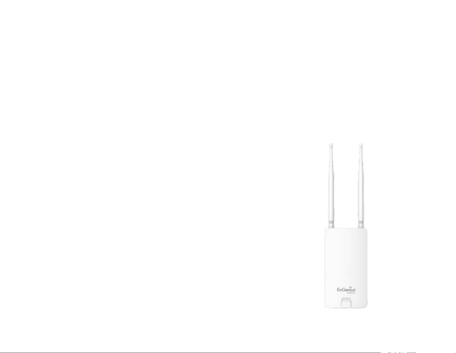
Introduction
The EnStation5-ACv2/EnStationACv2/ENS500-ACv2/
ENS500EXT-ACv2 is a high-powered, ultra long-range 2x2
Wireless 802.11ac/a/n Outdoor Access Point with speeds
up to 867 Mbps on both its high-powered 5 GHz radios.
Builded in EnGenius EnJet solution, AP can transmit data
more efficiently, avoid collisions,and reduce latency and
packet losses. It can be configured as an: Access Point,
Client Bridge or WDS (AP & Station) when EnJet enable, or
Access Point, Client Bridge or WDS (AP, Station & Bridge)
when EnJet disable. The EnStation5-ACv2/EnStationACv2/
Introduction
ENS500-ACv2/ENS500EXT-ACv2 is designed to operate in
a variety of outdoor environments. Its high-powered, long-
range characteristicsmake it acost effective alternative to
ordinaryAccess Points thatdon’thave the range andreach
to connect to a growing number of wireless CPEs who
wish to connect to a business network. The EnStation5-
ENS500-ACv2/ETD500EXT
5
En St at i on5 -A Cv2 /
EnStationACv2
Page 6

6
ACv2/EnStationACv2/ENS500-ACv2/ENS500EXT-ACv2
supports the 5 GHz frequency band for communicating to
other 5GHz frequency bands Access Points concurrently.
Several EnStation5-ACv2/EnStationACv2/ENS500-ACv2/
ENS500EXT-ACv2s can be networked in a campus setting
using the 5 GHz band between countries, which is easy
to be installed in virtually any location with its included
PoE (Power over Ethernet) Adapter for quick outdoor
installation. The EnStation5-ACv2/EnStationACv2/
ENS500-ACv2/ENS500EXT-ACv2 enables network
administrators to control its transmit power and features
settings for selecting VHT80 bandwidth to perform ture
AC transmission. When EnJet enable, administrators can
adjust the AP time slot and Station Priority to maximize
transmissionefficiency.It alsosupportswirelessencryption
including Wi-Fi Protected Access (WPA2-PSK) Encryption
and IEEE802.1X withRADIUS.)
Page 7

7
System Requirements
The following are the Minimum System Requirements in
order to configure thedevice.
• Computerwith an Ethernetinterfaceor wirelessnetworkcapability
• Windows OS (XP, Vista, 7, 8, 10), Mac OS, or Linux-based operating
systems
• Web-Browsing Application (i.e.: Internet Explorer, Firefox, Safari, or
anothersimilar browserapplication)
Package Contents
The EnStation5-ACv2/EnStationACv2packagecontainsthe
followingitems:*
•EnStation5-ACv2/EnStationACv2 Customer PremisesEquipment
•EnStation5-ACv2 withPoEAdapterEPA2406GR/EnStationACv2 with
PoE AdapterEPA5006GR
•PowerCord
•Pole MountStrap
•WallMountBracketBase
•Screw SetsKit
•Rubber
•SealingNut
•DynamicStick
•Quick InstallationGuide
*(allitemsmustbe in packageto issuea refund):
The ENS500-ACv2/ENS500EXT-ACv2 package contains
the followingitems:*
•ENS500-ACv2/ENS500EXT-ACv2
•5GHzDetachableAntennas*2 (ENS500EXT-ACv2)
•PoE Adapter(EPA2406GR)
•PowerCord
•Pole MountStrap
•WallMountScrewSet
•Quick InstallationGuide
*(allitemsmustbe in packageto issuearefund):
Page 8

8
WDS Bridge
WDSStation
Optimal Performance
Distance Control (AckTimeout)
Multicast Supported
Data Rate Selection
Auto ChannelSelection
BSSIDSupport
AP Time Slot
Station Priority
Easily Management
VLAN Tag / VLANPass-through
Guest Network
QoS: Complaint with IEEE 802.11e/WMM
RADIUSAccounting
Wireless STA (Client) connectionlist
Traffic Shaping (PerSSID)
Intuitive Tools
SNMP v1/v2c/v3support
MIB I/II, Private MIB
Save Configuration as Default
CLISupport
WiFi-Scheduler/Auto Reboot
E-mail Alert
Reinforcement Security
WPA2 Enterprise
Hide SSID in beacons
MAC address filtering, up to 32 MACs per SSID
Wireless STA (Client) connectionlist
Standard:
IEEE802.11ac wave2/a/n on 5 GHz
Antenna
Internal 15.5dBi high gain directional antenna (EnStation5-ACv2/
EnStationACv2)
Internal 13.42dBi high gain directional antenna (ENS500-ACv2)
External 2*5.17dBi detachable antenna (ENS500EXT-ACv2)
Physical Interface
2 x 10/100/1000 Gigabit Ethernet Port with PoE support
EnStation5-ACv2/EnStationACv2 LAN(PoE) Port supports
24V/54V PoEInput
LED Indicator
Power
LAN1
LAN2
WLAN
WLAN LED (Weak, Medium,Strong)
Power Requirements
EnStation5-ACv2/EnStationACv2 Include PoE Adapter, 24V
0.6A/54V 0.6A
Operation Modes-EnJetenable
Access Point
Client Bridge
WDS AP
WDS Station
Operation Modes-EnJetdisable
Access Point
Client Bridge
WDS AP
Technical Specifications
Page 9

9
Https Support
SSHSupport
QoS (Quality of Service)
Complaint with IEEE 802.11estandard
Physical/Environment Conditions
Operating:
Temperature: -20 °C to 60 °C (-4 °F to 140°F)
Humidity (non-condensing): 90% or less
Storage:
Temperature: -30 °C to 80 °C (-22 °F to 176°F )
Humidity (non-condensing): 90% or less
Page 10
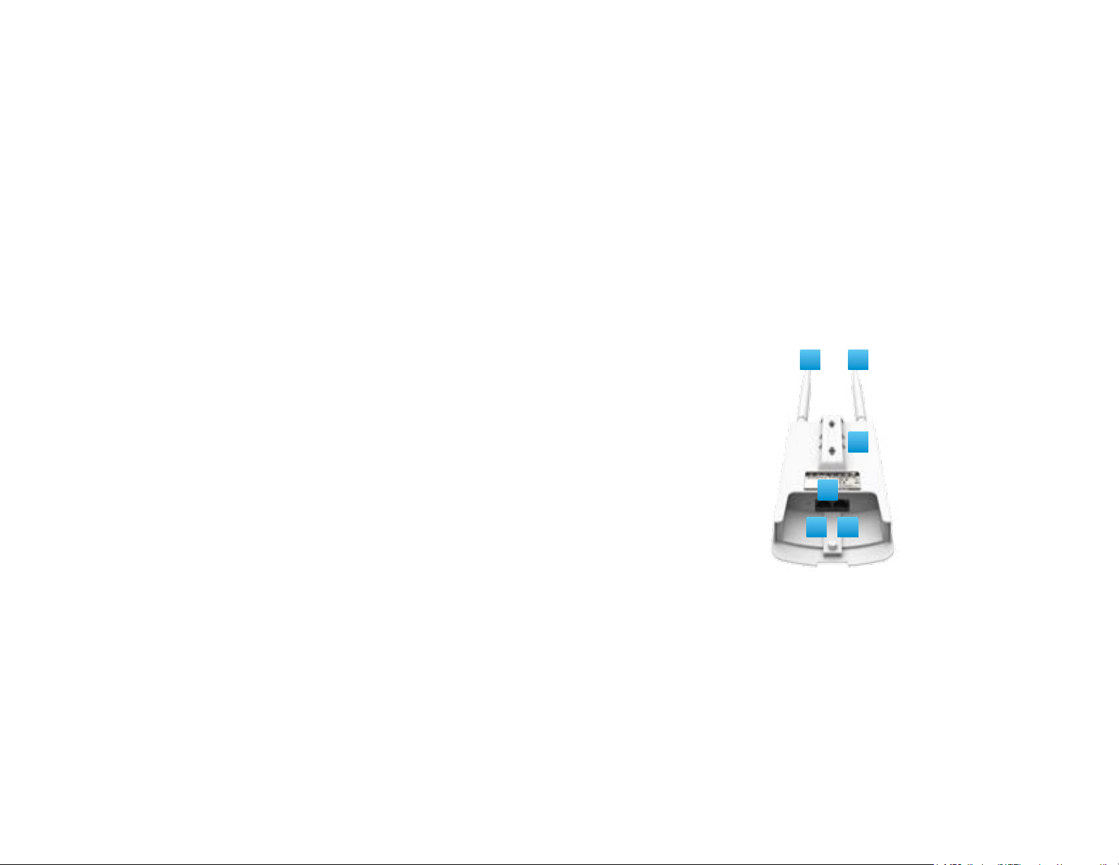
Physical Interface-EnStation5-ACv2/EnStationACv2
Dimensions and Weights
EnStation5-ACv2/EnStationACv2
Dimension: 190mm(7.48”)
Height: 38mm (1.9”)
Weight: 527g (1.16lbs)
1 WLAN Signal LED: Applied on Client Bridge/WDS
(1)Red: Weak Signal: Connecting quality isbad.
(2)Yellow: Connecting quality isNormal.
(3)Green: Connection quality isGood.
2 LAN(PoE) Signal LED
3 LAN Signal LED of the 2nd Port
4 Power Signal:
5 LAN Port 1: GigabitEthernet portforRJ-45 cable.
6 LAN Port 2: Gigabit Ethernet port for RJ-45 cable.
5
1
6
2
3
4
10
Page 11
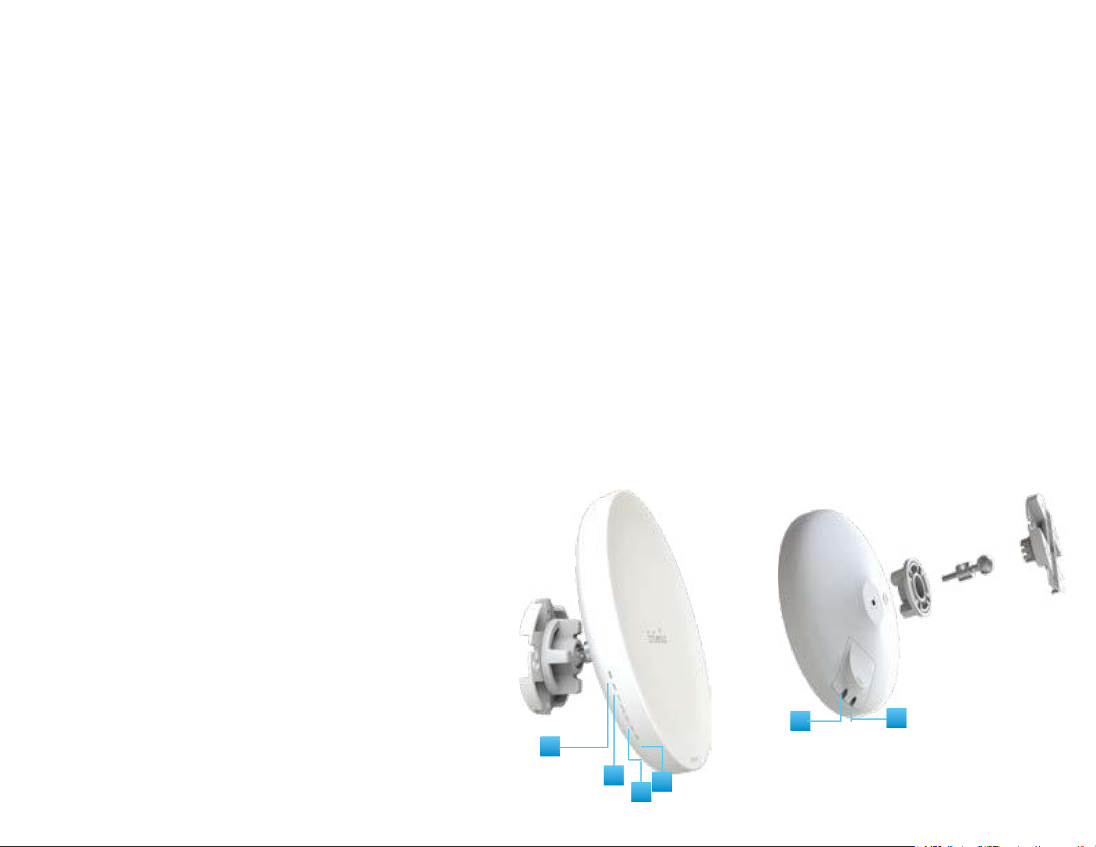
Physical Interface -ENS500-ACv2/ENS500EXT-ACv2
Dimensions
Length: 186 mm(7.32”)
Width: 100 (3.94”)
Depth: 29mm(1.14”)
1 5 GHz Antennas Detachable 5 dBi 5 GHz Omni-directional
Antennas (ENS500EXT-ACv2Only)
2 LAN Port 1 (Proprietary24V PoE): Ethernet portforRJ-45 cable.
3 LAN Port 2 :Ethernet port for RJ-45 cable.
4 LED Indicators: LED lights for Power, LAN Port 1, LAN Port 2,
2.4 GHz Connection and 5GHz Connection.
5 Mounting Holes: Using the provided hardware, the AP can be
attached to a wall or pole.
*Theinstallation angleof antenna must be vertical to the ground.
4
3 2
1 1
5
11
Page 12
Chapter 2
Before You Begin
12
Page 13
Windows XP/Windows 7/Windows 8/Windows
10
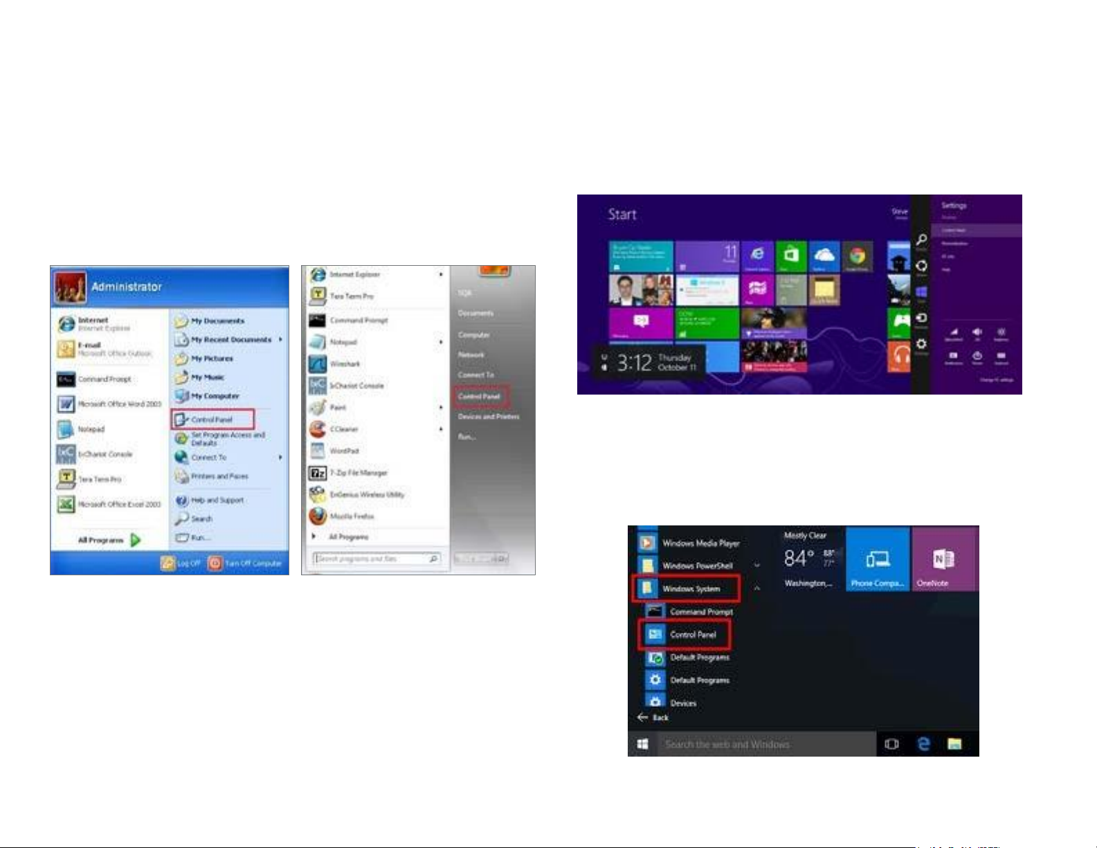
In orderto usethe AccessPoint,youmustfirstconfigurethe
TCP/IPv4connectionof yourWindowsOS computersystem.
1a. Clickthe Start button and open the Control Panel
1b. Move your mouse to the lower right hot corner to
display the Charms Bar and select the Control Panel in
Windows 8 OS.
Computer Settings
WindowsXP Windows7
Windows 8
1c. In Windows 10, click Start to select All APPs to enter
the folder of Windows system for selecting Control
Panel.
Windows10
13
Page 14
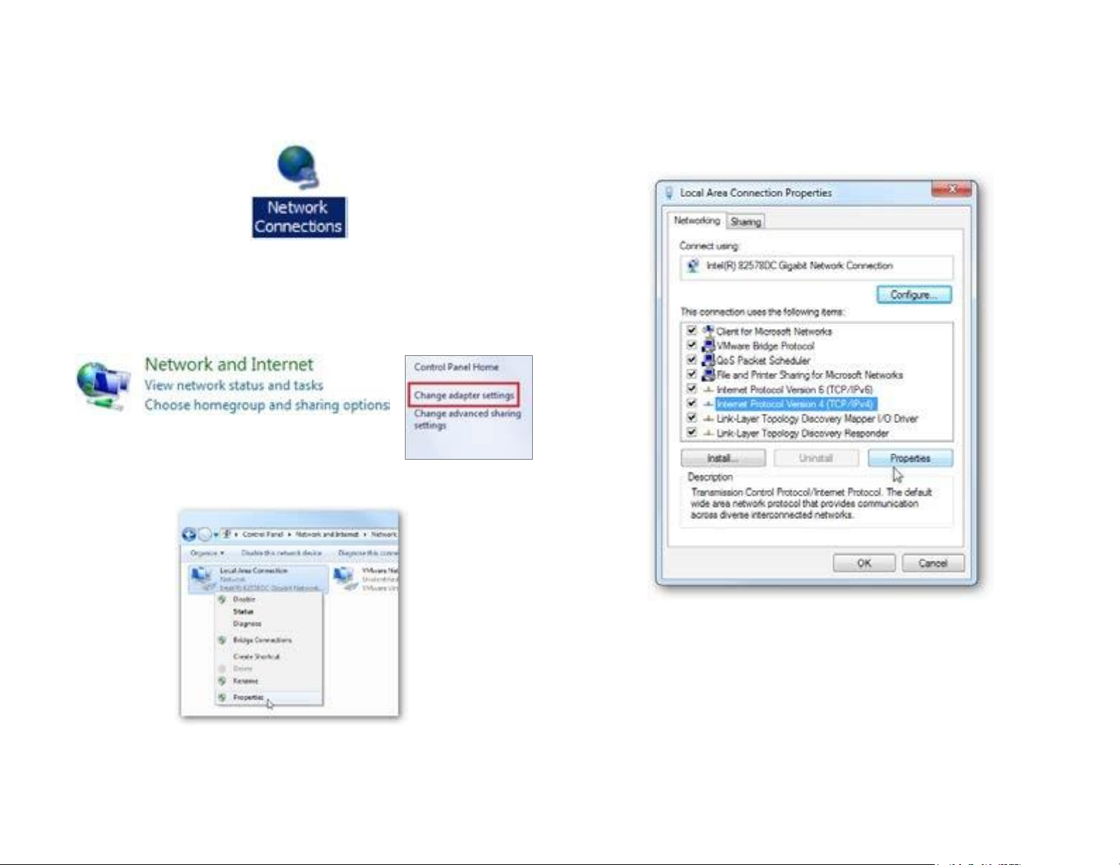
2a.InWindows XP, clickNetwork Connections.
2b.In Windows 7/Windows 8/Windows 10, click View
Network Status and Tasks in the Network and
Internetsection,thenselectChange adaptersettings.
3. RightclickonLocalAreaConnectionandselectProperties.
4. Select Internet Protocol Version 4 (TCP/IPv4) and then
selectProperties.
5. Select Use the following IP address and enter an IP
addressthatis different fromtheAccessPointandSubnet
mask,thenclick OK.
14
Page 15
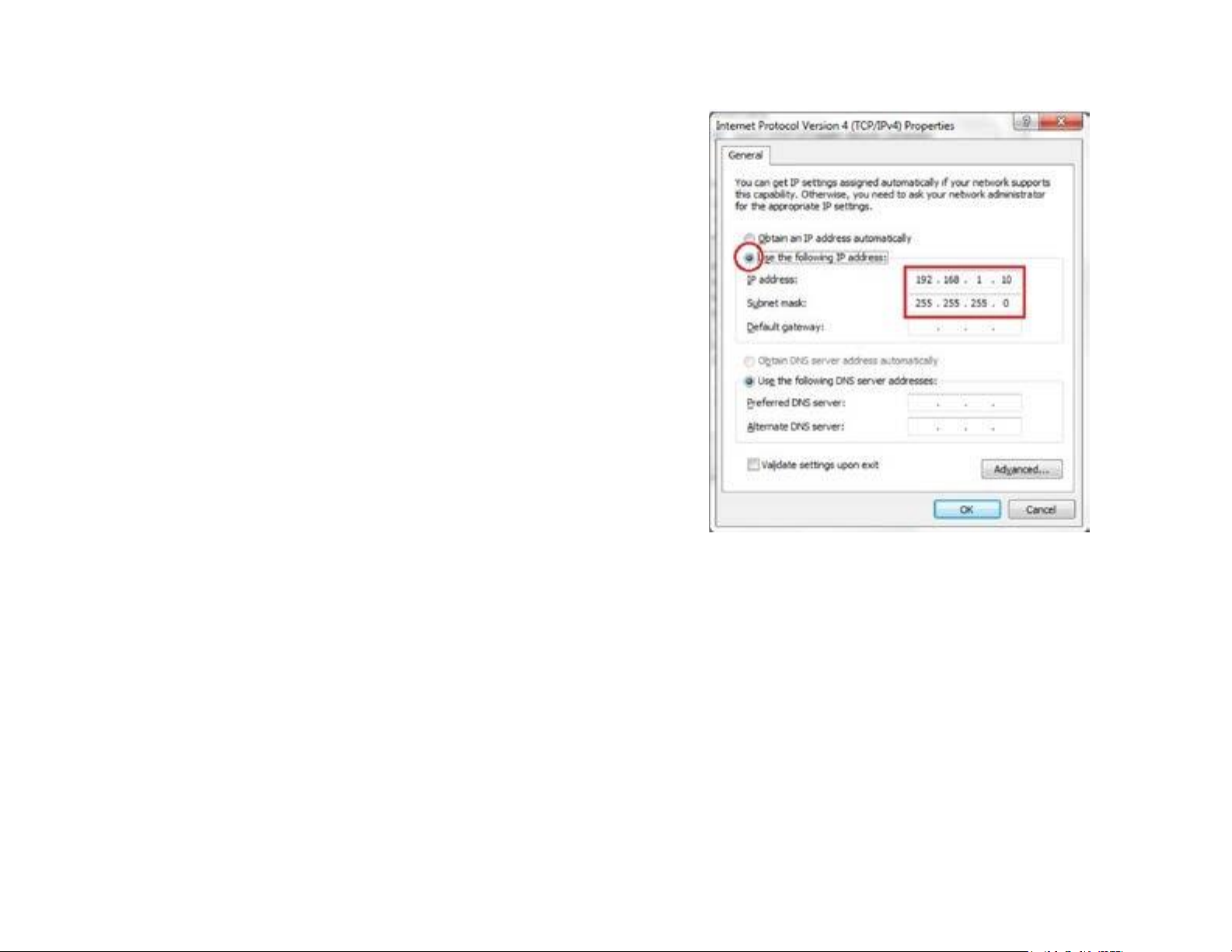
Note: Ensure that the IP address and Subnet mask are
on the samesubnet as the device.
For example: ENH220EXT IP address: 192.168.1.1
PCIPaddress:192.168.1.2–192.168.1.255
PC Subnet mask:255.255.255.0
15
Page 16
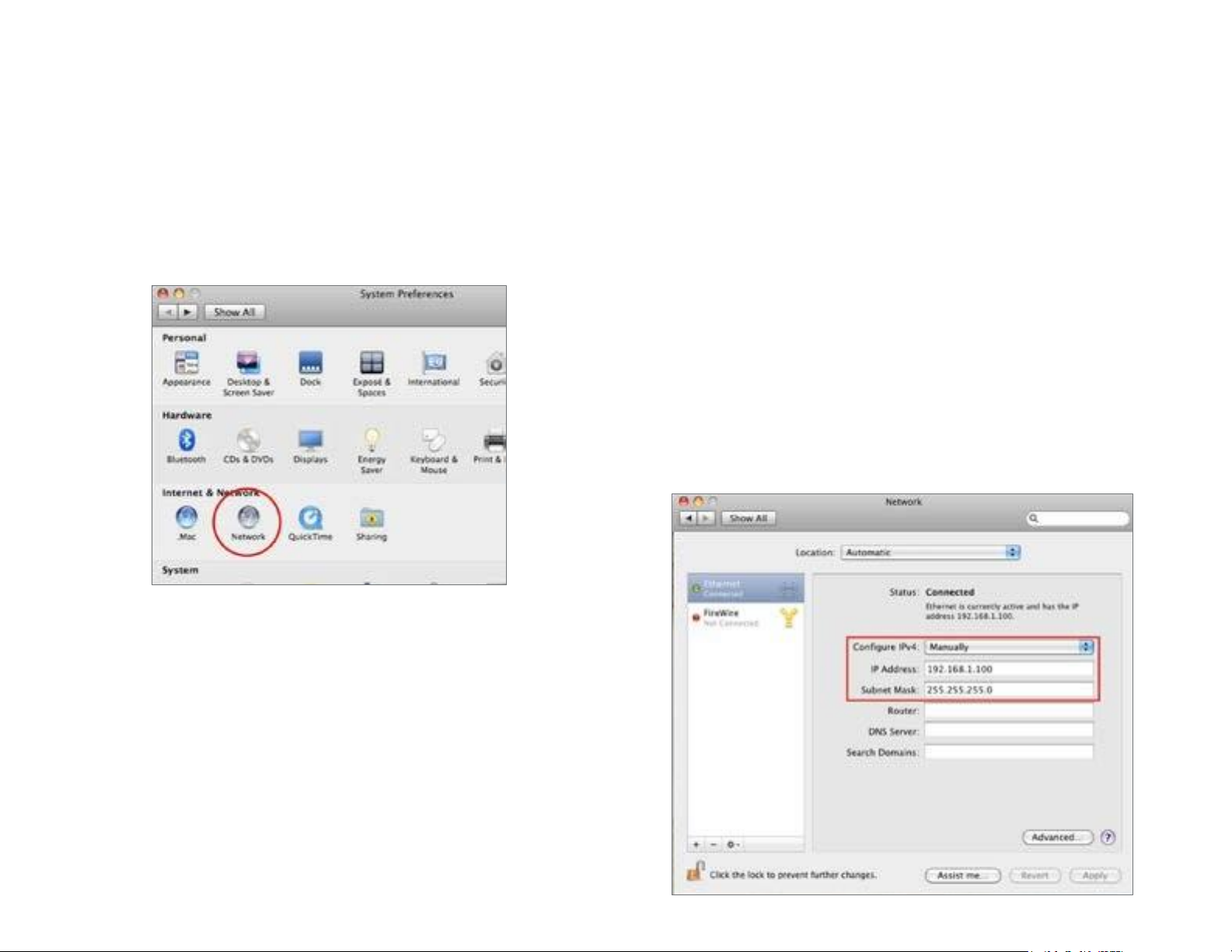
Apple Mac OSX
1. Go to System Preferences (Whichcanbe openedin the
Applications folder or selecting it in the Apple Menu).
2. Select Network in the Internet & Network section.
3. Highlight Ethernet.
4. In Configure IPv4, selectManually.
5. Enter an IP address that is different from the Access
PointandSubnet maskthen press OK.
Note: Ensure that the IP address and Subnet mask are
on the same subnetas the device.
For example: ENH900EXT IP address: 192.168.1.1
PCIPaddress:192.168.1.2–192.168.1.255
PC Subnet mask:255.255.255.0
6. Click Apply whendone.
16
Page 17
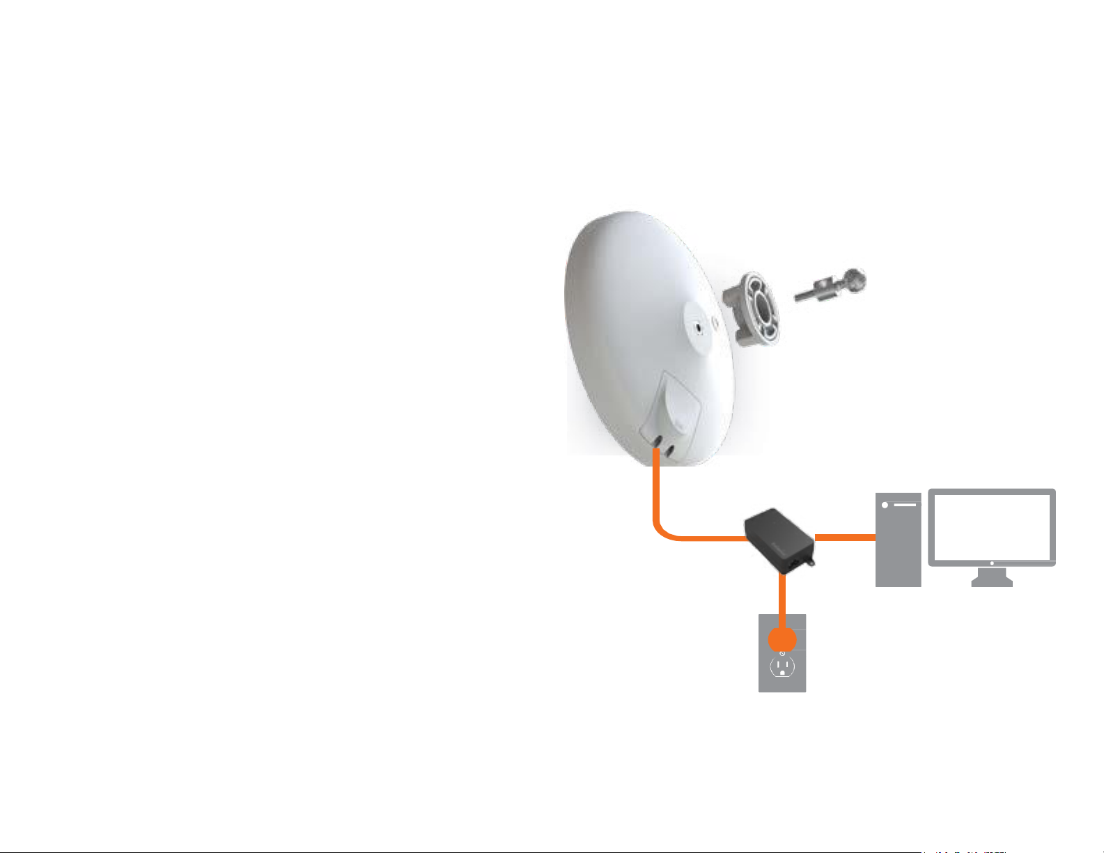
1. Remove the rear bottompanel.
2. Connect one end of the Ethernet cable into the main
LAN port (PoE) of the Access Point and the other endto
the AP Ethernet port on the PoE Adapter.
3. Connect the Power cord to the PoE Adapter and plug
the other endin to an electrical outlet.
4. Connectthe second Ethernet cable intothe LAN port of
the PoE Adapter and the otherend to the Ethernet port
on the computer.
5. Place the panel back intodevice
Note: The EnStationACv2 should ONLY be powered via
Ethernetcableconnected to included supportsbothIEEE
802.3at PoE (Power over Ethernet) or the included PoE
Adapter. You may use either one as the power source.
Do NOTuse both at the same time.
Note:The EnStationACv2cansupplythe 802.3af power
sourcewhenusedwithincludedPoE Adapter.
Hardware Installation
EnStation5-ACv2/EnStationACv2
Ethernet
PC
Power
Outlet
PoE Adapter
17
Page 18

Mounting the EnStation5-ACv2/EnStationACv2
Using the providedhardware, the EnStation5-ACv2can be attached to a wall or a pole.
1. ETD
5. Screw SetKit 6. SealingNut
4. PoleMounting Strap
7. DynamicStick 8. Rubber
2. PoE Adapter& 3. Bracket
Power Cord
18
Page 19
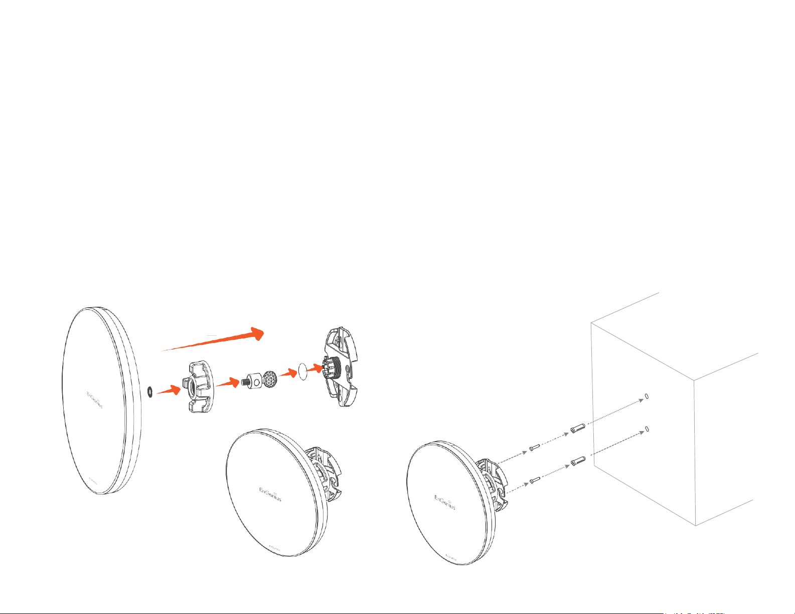
Wall mounting theEnStation5-ACv2/
EnStationACv2
1. Put the included rubber into the bracket.
2. Plug the dynamicstickinto the bracket.
3. Screwthe sealing nut andassembledparts,as well as
tighten it.
4. Put the nockwasher on the dynamicstick.
5. Assemblet he mountingpartsto the EnStation. .
6. Determine the mountinglocation.Mark and drill two
pilotholes aligning to the screw holesof the bracket
7. Put wall anchors into the holesandinsert screw into the
wall anchor.
8. Screwandsecruethe bracketin the place.
1
2
3
4
5
6
7
8
B
A
Dimension:
A: Ø 5.5*18 mm
B: Ø 8*25 mm
19
Page 20
1
2
3
4
5
6
20
7
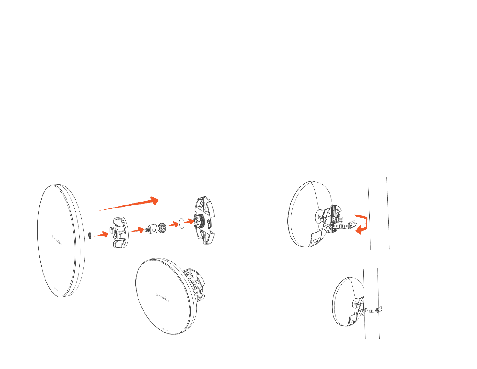
Pole mounting the EnStation5-ACv2/
EnStationACv2
1. Put the included rubber into the bracket.
2. Plug the dynamicstickinto the bracket.
3. Screwthe sealing nut andassembledparts,as well as
tighten it.
4. Put the nockwasher on the dynamicstick.
5. Assemblet he mountingpartsto the EnStation. .
6. Thread the open end of the pole strap through the two
tabs on thebracket.
7. Lockandtighten polestrapto securebracketto the pole
Page 21
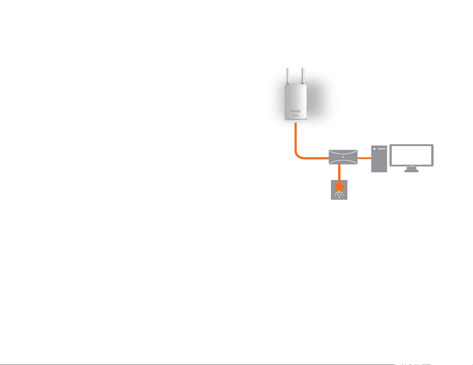
1. Connect one endof the Ethernet cable intothe LAN port
(PoE) of the AP/ Bridge and the other end to the PoE
port on the PoE adapter.
2. Connect the Power cord with the PoE Adapter and plug
the other endinto an electrical outlet.
3. Connectthe second Ethernet cable into the LAN port of
the PoE adapter and the other end to the Ethernet port
on the computer.
4. Screwon the providedantennasto the top of thisdevice.
Note: The AP/Bridge should ONLY be powered via
Ethernet cable connected to the includedPoE Adapter.
This diagramdepicts the hardware configuration.
Note: The AP/Bridge should ONLY be powered via
Ethernet cable connectedto the includedPoE Adapter.
Hardware Installation
ENS500-ACv2/ENS500EXT-ACv2
21
Page 22

Mounting the ENS500-ACv2/ENS500EXT-ACv2
Usingthe provided hardware, the ENS202EXT canbe attached to a wall or a pole.The heightshould not exceed 2 meter.
1. Wall MountingKit
(Anchors:Φ5.5*18mm&Bolts:Φ8*25mm)
2. PoleMounting Strap
(Φ66*12.6 mm)
Anchors
Bolts
22
Page 23

To attach the ENS500-ACv2/ENS500EXT-ACv2
to a wall using wall mounting kit.
A. Determine where the Access Point to be placed and
stick the Adhesive label on the surface.
B. Use the appropriate drill bit to drill two 8.1mm
diagramand 26mmdepth holes on the markings of the
label.
C. Removethe label andscrewthe anchors unto the holes
until they are flushwiththe wall.
D. Screw the included screws into the anchors. Place the
AccessPointagainstwallwiththemountingscrewheads.
To attach the ENS500EXT-ACv2 to a pole using
the provided pole mounting kit:
A. Thread the openend of the Pole Strapthrough the two
tabs on the Pole MountBracket.
B.LockandtightenPoleStrapto secure Pole MountBracket
to thepole.
23
Page 24

Chapter 3
Configuring Your
Access Point
24
Page 25

This section will show you how to configure the device
usingthe web-based configuration interface.
Default Settings
Pleaseuse yourEthernetportor wireless networkadapter
to connect theAccess Point.
IP
Address
192.168.1.1
Username /
Password
admin
/admin
Web Configuration
1. Open a web browser (Internet Explorer/Firefox/Safari/
Chrome) and enter theIP Address http://192.168.1.1
Note: If you havechangedthe default LANIP Addressof
the AccessPoint,ensureyouenterthe correctIP Address.
2. The default username and password are admin. Once
you have entered the correct username and
password, click the Login button to open the web-base
configurationpage.
*The model name will be varied by different models
3. If successful, you will be logged in and see the
EnStationAC UserInterface.
Configuring Your Access Point
25
Page 26

Chapter 4
Building a Wireless
Network
26
Page 27

Before starting to configure this Access Point, you may realize the used scenario under varied operating modes. The
EnStation5-ACv2/EnStationACv2/ENS500-ACv2/ENS500EXT-ACv2 is built in EnGenius EnJet solution, AP can transmit
data moreefficiently, avoidcollisions,andreduce latencyand packetlosses. WhenEnJet enable, it canbe configured as an:
Access Point, Client Bridgeor WDS(AP & Station) or Access Point,Client Bridge or WDS(AP, Station & Bridge)when EnJet
disable. This chapter describes purpose of different operating modesand lists down the operating modesfor outdoor
Access Points or ClientPremiseEquipments (CPE).
Access Point Mode
In AccessPointMode,AP/CPEbehaveslikesacentralconnectionforstationsor clientsthatsupportIEEE802.11ac/a/nnetworks.
The stations and clients must be configured to use the same SSID(ServiceSet Identifier) andsecuritypassword to associate
withthe EnStationAC.The EnStationACsupportsup to eight(8)SSIDsperbandat the sametimeforsecure access.
27
Page 28

Client Bridge Mode
The AP/CPE essentially acts as a wireless adapter that connects to an access point to allow a system of wireless access
to the network in the ClientBridge mode.Since the computersareon the samesubnet,the AP/CPEcanbroadcastto reach
all end-devices.
If you use the client bridge mode in the AP/CPE, you can use the AP Detection feature to scan for Access Points within
range. When you find an Access Point, configure the AP/CPE to use the same SSIDand Security Password as the Access
Point to associate with it.
28
Page 29

WDS AP Mode
The AP/CPE also supports WDS AP mode. This operating mode allows wireless connections to the AP/CPE using WDS
technology. In this mode, configure the MAC addresses in both Access Points to enlarge the wireless area by enabling
WDSLink settings. WDSsupports up to four (4)AP MACaddresses.
29
Page 30

WDS Bridge Mode
In WDS Bridge Mode, the AP/CPE can wirelessly connect different LANs by configuring the MAC address and security
settings of each AP/CPEdevice. Usethismodewhentwo wired LANs located a small distanceapartwantto communicate
with each other. The best solution is to use the AP/CPEto wirelesslyconnect two wired LANs,as shown in the following
diagram.
WDSBridgeModecanestablish up to four WDSlinks, creating a star-likenetwork.
Note: WDSBridge Mode does not act as an Access Point.AccessPoints linked by WDS are usingthe same frequency
channel.MoreAccess Points connected together maylower throughput.
AP
WDSBridge
30
AP
WDSBridge-
AP
WDSBridge-
Client
Computer
Client
Computer
Client
Computer
Page 31

WDS Station Mode
Station mode expands the WDSby receiving a wirelesssignal/serviceand sharing it through the Ethernet port.
AccessPoint
WDS AP
31
AccessPoint
WDSStation
AccessPoint
WDSStation
AccessPoint
WDSStation
Page 32

Chapter 5
Status
32
Page 33

Save Changes
This pageletsyousave andapplythesettingsshownunder
Unsaved changes list, or cancel the unsaved changes and
revertto the previous settingsthat werein effect.
*The model namewill be varied by different models.
Device Status
Clicking the Device Status link under the Overview menu
shows the status information about the current operating
mode.
• The Device Information section shows general system
informationsuch as DeviceName,MACAddress,Current
Time,Firmware Version,and ManagementVLANID
Note: VLAN ID information is only applicable in Access
Point or WDS APmode.
*The model name will be varied by different models.
• The Memory Information section shows usage of
memorysuchas Total Available, Free, Cached,Buffered
MainStatus
33
Page 34

• The LAN Information section shows the Local Area
Network settings such as the LAN IP Address, Subnet
mask, and DNSAddress.
• The Wireless LAN Information 5 GHz section shows
wirelessinformationsuchasOperatingMode,Frequency,
and Channel. Since the AP/CPE supports multiple-SSIDs,
information about each SSID, the ESSID, and security
settings, aredisplayed
Note:ProfileSettings are onlyapplicableinAccessPoint
and WDS AP modes.
• The Statistics section shows Mac information such as
SSID, MAC address, RX andTX.
34
Page 35

5GHz Connection List
Clickthe connection linkundertheOverview menudisplays
the connection list of clients associated to the AP/CPE’s 5
GHz, along with the MAC addresses and signalstrength for
each client. Clicking Refresh updates the clientlist.
Note: Only applicable in Access Point and WDSAP
modes.
WDS Link List
Click the connection link under the Overview menu. This
page displays the current status of the WDS link, including
WDSLinkID,MACAddress,Link Status andRSSI.
Note:Only applicablein WDSAP andWDSBridgemodes.
Traffic Loading: 5GHz and Ethernet port inbound and
outbound traffic by current,averageand peak time.
Connection Realtime
The Realtime section contains the following options:
CPU Loading: 3 minutes CPU loading percentage
information, it displays current loading, average loading
and peak loading status. Left bar is loading percentage;
button is time tracing. Intervalis every3 seconds
35
Page 36

Realtime Connection (Pkts): Overview on current
active network connections. It displays UDP and TCP
packets information and other connection status. UDP
connections curve is in blue; TCP connection curve is
in green; others curve is in red. Below of chart shows
connections source anddestination.
36
Page 37

Chapter 6
Network
37
Page 38

IPv4/IPv6 Settings
This page allows youto modifythe device’sIP settings.
IP Network Settings:Selectwhetherthe device IP address
will use a static IP address specified in the IP address field
or be obtained automatically when the device connects to
a DHCPserver.
IP Address:The IP address of thisdevice.
Subnet Mask: The IP Subnet maskof this device.
Gateway: The Default Gateway of this device. Leave it
blank if you are unsure of this setting.
Primary/Secondary DNS: The primary/secondary DNS
address for thisdevice.
Save: ClickSave to confirmthe changes.
Spanning Tree Protocol(STP) Settings
This page allows youto modify the SpanningTreesettings.
Enabling the Spanning Tree protocol will prevent network
loops in yourLAN network.
Spanning Tree Status: Enables or disables the Spanning
Tree function.
Hello Time: Specifies Bridge Hello Time in seconds. This
value determines how often the device sends handshake
packets to communicate information about the topology
throughout the entireBridgedLocalArea Network.
Max Age: Specifies Bridge Max Age in seconds. If another
bridgein the spanningtree does not sendahello packetfor
a long periodof time,it is assumed to be inactive.
Basic IPSettings
38
Page 39

39
Forward Delay:Specifies BridgeForward Delayin seconds.
Forwarding delay time is the time spent in each of the
Listening and Learning states before the Forwardingstate
is entered.This delay is providedso that when anew bridge
comes onto a busynetwork, it analyzes data traffic before
participating in thenetwork.
Priority: Specifies the Priority Number.A smaller number
hasa greaterpriority than a largernumber.
Save: ClickSave to confirm the changes.
Page 40

Chapter 7
Wireless
40
Page 41

Wireless Settings
*The model namewill be varied by different models.
Device Name: Enter a name for the device. The name you
type appears in SNMP management. This name is not the
SSIDand is not broadcastto other devices.
Save: ClickSave to confirm the changes.
EnJet
The AP/CPE is default EnJet enable. When enable the
EnGenius EnJet system,the AP/CPE can then transmit data
more efficiently, avoid collisions, and reduce latency and
packet losses.(Ifyou do not enable EnJet, data will be sent
via traditional CSMA.)
Wireless
41
Page 42

This page displays the current status of the Wireless
settings ofthe AP/CPE.
Wireless Network
EnStation5-ACv2/EnStationACv2/ENS500-ACv2/
ENS500EXT-ACv2 Wireless: The AP/CPE supports
802.11ac/n mixedmode in 5 GHz.
Operation Mode: Select Operation Mode. When EnJet
enable, The AP/CPE can be seted as Access Point, Client
Bridgeor WDS(AP& Station) or AccessPoint, ClientBridge
or WDS(AP, Station & Bridge) when EnJet disable.
Channel HT Mode: The default channel bandwidth is 20
MHz/ 40 /80 MHz. The larger the channel, the greater the
transmission quality andspeed.
Channel: Click Configuration button to open a new
windows to configure channels for performing wireless
service.
Transmit Power: Sets the power output of the wireless
signal.
Bit Rate: 5GHz is default 6 Mbps, the range can control
by BAR via scroll from 6Mbps to 54Mbps.
Client Limits: When EnJet enable, limits the total number
of clients. Once setting the ceiling of client numbers, the
maximum assocaited client devices will be restricted at
this number.
AP Detection:AP Detectioncan selectthe bestchannel to
42
Page 43

useby scanning nearby areasfor Access Points.
Distance: Specifies the distance between Access Points
and client devices. The proper setting for this parameter
may assist Access Points to avoid the improper operation
when transmitting dataunder a filedapplication.
AP Time Slot:In EnJet mode, the AP will assign time slots
for each client’s data transmission. The larger the slot, the
faster the datatransmission.
Station Priority:In EnJet mode, the client bridge/WDS
station’s data transmissionis prioritized by data. High level
meansalongertransmissiontime.(The timeratiois 10:5:1.)
Wireless Setting-5GHz
Current Profile: You can configure up to seven(7)different
SSIDswhen EnJet disable or 1 SSID when EnJet enable. If
multiple client devices will be accessing the network,
you can arrange the devices into SSID groups. Click Edit
to configure the profile and check whether you want to
enable extraSSID.
SSIDProfile when EnJet disable
SSIDProfile when EnJet enable
Management Interface: This Management interface make
you can to get on and change the configuration of the
device from remote instead of using the GUI.
Enable: Click this check box to enable this SSID interface.
The default SSIDsare enable on the first 5GHz SSID.
SSID:Specifies the SSIDforthe current profile.
43
Page 44

44
HiddenSSID:Checkthisoptionto hidethe SSIDfromclients.
If checked, the SSIDwill not appearin the sitesurvey.
ClientIsolation:Clicktheappropriateradiobuttontoenable
this function for allowing or preventing communication
between clientdevices.
VLAN Isolation: Restrict clients communicating with
differentVIDsby selectingthe radio button.
L2 Isolation: Enable this function prevenet client devices
to communicate on the both WLANandLAN.
VLAN ID: Specifies the VLAN tag for each profile. If your
netowrk includes VLANs, you can specify a VLAN ID for
packets pass through the Access Pointwithatag.
WirelessSecurity: Seethe Wireless Security section.
Save: ClickSave to accept the changes.
Page 45

Wireless Security
The Wireless Security section lets you configure the AP’s
security modes
Secuirty Mode:IncludingWPA2-PSK,WPA2-Enterprise. We
stronglyrecommendyou to use WPA2-PSK mode.
*Setting of WPA2-Enterprise (Pre-Shared Key):
Encryption:Defaultis AES.Pleaseensurethatyourwireless
clients use thesame settings.
Group Key Update Interval: Specifies how often, in
seconds,the GroupKeychanges.The default valueis 3600
Radius Server: Enter the IP address of the Radiusserver.
Radius Port: Enter the port number used for connections
to the Radiusserver.
Radius Secret: Enter the secret required to connectto the
Radius server.
45
Page 46

Radius Settings
NAS-ID: Enable or disable accounting feature.
NAS-Port: Enableor disable accountingfeature.
NAS-IP: Enableor disable accounting feature.
Radius Accounting
Radius Accounting: Enableor disable accounting feature.
Radius Accounting Server: Enter the IP address of the
Radius accountingserver.
Radius Accounting Port Enter the port number used for
connections to the Radius accounting server.
Radius Accounting Secret: Enter the secret requiredto
connect to the Radiusaccountingserver.
Interim Accounting Interval: Specifies how often, in
seconds, theaccounting data sends.
Note: 802.11n does not allow WPA2-PSK TKIP security
mode. The connection mode will automatically change
from 802.11n to 802.11g.
FastRoaming
Enable the function to serve mobile client devices that roam
fromAccess Pointto Access Point. Someapplications running
on Client devices require fast re-association when they roam
to adifferentAccessPoint
Pleaseenterthe settingsof the SSIDandinitializetheSecurity
mode to WPA2 enterprise, as well as to set the RadiusServer
firstly. Users canenablethe Fast Roamingand implementthe
advancedsearch.
Please also set the same enterprise Encryption under the
same SSID on other Access Points and enable the Fast
Roaming. When the configuration is realized on different
Access Point, the mobile client devices can run the voice
service and require seamless roaming to prevent delay in
conversation from Access Point to Access Point.
46
Page 47

Wireless MACFiltering
Wireless MAC Filtering is used to allow or deny network
access to wireless clients (computers, tablet PCs, NAS,
smartphones, etc.) according to their MAC addresses. You
can manually add a MAC address to restrict permission to
access the AP/CPE. The defaultsettingis:Disable Wireless
MAC Filter.
Note: Only applicable in Access Point and WDSAP
modes.
ACLMode: Determines whether network accessis granted
or denied to clients whose MAC addresses appear in the
MAC addresstable on this page. Your choices are:Disabled,
DenyMACin the list,or Allow MAC in the list.
MAC Address:Enterthe MACaddressof the wirelessclient.
Add: ClickAdd to add the MAC address to the MAC address
table.
Delete:Deletethe selectedentries.
Save: ClickSave to apply the changes.
47
Page 48

Wireless Traffic Shaping
Traffic shaping regulates the flow of packets leaving an
interface to deliver improved Quality of Service. The
function will allow administrators to restrict the wireless
bandwidth perSSID.
Enable Traffic Shaping: Check this option to enable
Wireless TrafficShaping.
Download Limit: Specifies the wireless transmission
bandwidth used fordownloading.
transmissionUpload Limit: Specifies the wireless
bandwidth used foruploading.
Save: ClickSave to confirmthe changes.
48
Page 49

Guest Network Settings
Adding a guest network when EnJet disable allows
visitors to use the Internet without giving out your office
or company wireless security key. You can add a guest
network to each wireless network in the 5 GHz ac/a/n
frequencies.
SSID:Specifies the SSIDforthe current profile.
Suppressed SSID: Check this option to hide the SSIDfrom
clients.If checked,the SSIDwillnot appearin the sitesurvey.
Station Separation: Click the appropriate radio button to
allow or prevent communicationbetween clientdevices.
IP Address: The IP Addressof this device.
Subnet Mask: The IP Subnet maskof this device.
Starting IP Address: The first IP Address in the rangeof
the addressesby the DHCP server.
Ending IP Address: The last IP Address in the range of
addresses assigned by theDHCP server.
RSSI Threshold
RSSI Threshold: Enable the Fast Handover feature when
EnJet disable by ensuring that each client is served by at
least one Access Point at any time. Access Points
continuously monitor the connectivity quality of any
client in their range and efficiently share this information
with other Access Points in the vincinity of that client to
coordinatewhichof themshouldserve the clientbest.
RSSI: Enter the RSSI (Received Signal Strength Index) in
order to determine the handover procedure which the
current wireless link will terminate. RSSI is an indication of
the power level being received by the antenna. Therefore,
the higher the RSSInumber, the stronger the signal.
49
Page 50

Management VLAN Settings
This page allows you to assign a VLAN tag to packets sent
over the network. A VLAN is a group of computers on a
network whose software hasbeen configured so that they
behave as if they were on a separate Local Area Network
(LAN). Computers on VLAN do not have to be physically
locatednext to one another on the LAN.
Note: Only applicable in Access Point and WDSAP
modes.
Management VLAN: If your network includes VLANs, you
can enable Management VLAN ID for packets passing
through the AccessPoint with a tag.
Save:ClickSaveto confirmthe changesor Cancelto cancel
and return toprevious settings.
Note: If you reconfigure the Management VLAN ID,you
may lose your connection to the EnStationAC. Verify
that the DHCP server supports the reconfigured VLAN
ID and then reconnect to the EnStationAC using the
new IP address.
50
Page 51

Chapter 8
Management
51
Page 52

SNMP Settings
This page allowsyouto assign the Contact Details, Location,
Community Name, and Trap Settings for a Simple Network
Management Protocol (SNMP). SNMP is a networking
management protocol used to monitor network attached
devices. SNMP allows messages (called protocol data units)
to be sent to various parts of the network. Upon receiving
these messages, SNMP compatible devices (called agents)
returns the data stored in their Management Information
Bases.
SNMP Enable/Disable: Enables or disablesthe SNMP
feature.
Contact: Specifies the contact detailsof the device.
Location: Specifies the location of the device.
Community Name (Read Only): Specifies the password
for the SNMP community for read only access.
CommunityName (Read/Write): Specifies the password
for the SNMP community with read/writeaccess.
Trap Destination Address:Specifies the IP address of the
computer that will receive the SNMP traps.
Trap Destination CommunityName: Specifies the
passwordfor the SNMPtrap community.
SNMPv3:Enables or disables the SNMPv3feature.
User Name:Specifies the username for SNMPv3.
Auth Protocol: Selects the authentication protocoltype:
MDS or SHA.
Auth Key:Specifies the authentication key.
Priv Protocol: Selects the privacyprotocoltype: DES.
Priv Key: Specifies the privacy key for privacy.
Engine ID: Specifies the engine ID for SNMPv3.
Apply Save:Click Apply Save to applythe changes.
Advanced Settings
52
Page 53

CLISettings
CLI: The Command Line Interface (CLI) allows you to type
commands instead of choosing them from a menu or
selecting an icon.
SSH: Enable Secure Shell (SSH)to make secure, encrypted
connections in the network. Secure Shell is a network
protocol that allows data to be exchanged using a secure
channelbetween two networkdevices.
HTTPS: Enable HTTPS to transfer and display web content
securely. The Hypertext Transfer Protocol over SSL(Secure
Socket Layer) is a TCP/IP protocol used by web servers to
transfer and display web contentsecurely.
Email Alert
You can use the Email Alert feature to send messages to
the configured email address when particular system
eventsoccur.
Note: Do NOT use your personal email address as it can
unnecessarilyexpose yourpersonal emaillogincredentials.
Usea separateemailaccountmadeforthis feature instead
From: Enter the email address to show the sender of the
email.
To:Enterthe address that you wish to send emails to.
Subject: Enter the text that you wish to appear in the
email’s subjectline.
53
Page 54

54
Username: Enter the username for the emailaccountthat
will be usedto send emails.
Password: Enter the password for the email account that
will be usedto send emails.
SMTP Server: Enter the IP address or hostname of the
outgoing SMTPserver.
Port: Enter the SMTP port number to use for outbound
emails.
Security Mode: Selects the security mode: SSL/TLS or
STARTTLS or None.
Apply: To save setting and take effect.
Page 55

Time Setting
This page allows you to set the internal clock of the
EnStationAC.
Manually Set Date and Time: Manually specifythe
date and time.
Automatically Get Date and Time: Select and check
whether you wish to enter the IP address of an NTP
server or use the default NTP server to havethe
internal clock set automatically.
Enable Daylight Saving: Check whetherdaylight
savings applies to your area.
Start: Select the day, month, and time when daylight
savings timestarts.
End: Selectthe day, month, and time when daylightsavings timesends.
TimeZone
55
Page 56

Auto RebootSettings
You can specify how often you wish toreboot the
EnStationAC.
Auto Reboot Setting: Enables or disables the Auto
Reboot function.
Frequency of Auto Reboot: Specifies how often you
wish to reboot the EnStationAC by Min, Hour, Day or
Week.
Timer: Select the day and enter the time you would like
to reboot automatically.
Save: Click Save to apply the changes.
56
Page 57

Wi-Fi Scheduler
The Wi-Fi Scheduler can be created for use in enforcing
rules. For example, if you wish to restrict web access to
Mon-Fri from 3pm to 8pm, you could create a schedule
selecting Mon, Tue,Wed, Thu and Fri while entering a Start
time of 3pm and End Time of 8pm to limit access to these
times.
Status: Enablesor disables the Wi-Fi scheduler function.
Wireless Radio: Select 2.4 GHz or 5 GHz from the dropdown list for the preferredbandtype.
SSID Selection: Select a SSIDfrom the drop-downlist.
ScheduleTemplates: Selectascheduletemplatefrom the
drop-downlist.
Day(s):Place acheckmarkin the boxesfor thedesired days
or select the All Week radio button to select all seven days
of theweek.
Duration: The StartTime is entered in two fields. The first
boxis for hours andthe second boxis for minutes. The End
Timeis entered in the same formatas the Start time.
57
Page 58

Ping TestParameters
This page allows you to analyze the connection quality of
the EnStationAC and trace the routing table to a target in
the network.
Target IP:Enterthe IP address you would like to search.
Ping Packet Size: Enter the packet size of each ping.
Number of Pings: Enter the number of times you wishto
ping.
Traceroute TestParameter
Target IP:Enter the IP address you wouldliketo trace
Nslookup TestParameter
Target IP/Domain Name:Enter the IP address or domain
nameyou wishto do Nslookuptest.
Speed Test Parameters
Target IP / Domain Name: Enter an IP address or domain
name you wish to impelement a speed test for realizing
the variance on wireless speed.
Time Period:Enter the time in secondsthat you would like
the test to implement for and in how manyintervals.
IPv4/IPv6 Port: This Access Points uses IPv4 5001 and
IPv660001 port forthe speed test.
Start: Clickstart to implement speed test.
Tools
58
Page 59

Device Discovery
This page allows you to discover devices from network
for Operation Mode, IP Address, System MAC Address and
Firmware version.
59
Page 60

Administrator Username: Enter a new username for
loggingin to the New Nameentry box.
Current Password: Enter the old password for logging in
to the Old Passwordentrybox.
New Password: Enter the new password for loggingin to
the New Password entry box.
Verify Password: Re-enter the new password in the
ConfirmPassword entry box for confirmation.
Apply: Click Apply to applythe changes.
Firmware Upgrade
This page allows you to upgrade the firmware of the
EnStationAC.
To Perform the FirmwareUpgrade:
1. Click the Choose File button and navigate the OS file
system to the location of the upgradefile.
2. Select the upgradefile.The nameof the file will appear
in the Upgrade File field.
3. Click the Upload button to commence the firmware
upgrade.
Note: The device is unavailable during the Firmware
upgrade process and must restart when the upgrade is
completed. Any connections to or through the device
will be lost.
Account
This page allows youto changethe EnStationAC username
and password. By default, the username is: admin and the
password is: admin. The password can contain from 0 to
12 alphanumericcharactersand is case sensitive.
Account Settings
Firmware
60
Page 61

Backup/Restore
Backup/Restore
This page allows you to save the current device
configurations. When you save your configurations,
you also can reload the saved configurations into the
device through the Restore Saved Settings from a file
section. If extreme problems occur, or if you have set
the AP incorrectly, you can use the Reset button in the
Revert to Factory Default Settings section to restore
all the configurations of the AP to the original default
settings.
Backup Setting: Click Export to save the current
configured settings.
Restore New Setting: To restore settings that have
been previously backed up, click Browse, select the
file, and click Restore.
Restore to Default: Click Reset button to restore the
AP to its factory defaultsettings.
61
Page 62

62
User Setting
The function allows you to backup the current device
configurations into the EnStationAC as the default
value. If extreme problems occur, or if you have set the
EnStationAC incorrectly, you can push the Reset button
to revert all the configurations of the EnStationAC to
the user default.
Back Up Setting as Default: Click Backup to backup
the user settings you would like to the device’s memory
for the defaultsettings.
Restore to User Default: Click Restore to restore user
settings to the factory standardsettings.
Note1: After setting the current settings as the default, you should click the Restore to Default on the
web interface for reverting the settings into the factory default instead of pushing the reset button.
Note2: Please write down your account and password before saving. The user settings will now become
the new default settings at the next successful login.
Page 63

Status: Enable/Disable thisfunction.
TraficLog: Enable/Disable this function.
Log type:You maychoose one of log typesto displaylogs
in the following window.The default log typesis All.
Remote Log
This page allows you to setupthe Remote Log functions
for the AP/CPE.
Syslog: Enables or disables the syslog function.
Log Server IP Address: Enter the IP address of thelog
server.
Remote Log: Enable or disable the remote log service.
Apply: Click Apply to apply thechanges.
Log
System Log
The EnStationAC automatically logs (records) events of
possible interest in its internal memory. To view the
logged information, click the Log link under the System
Manager menu. If there is not enough internal memory
to log all events, older events are deleted from the log.
When powered down or rebooted,the log will be cleared.
63
Page 64

Logout
Click Logout in Managementmenu to logout.
*The model name will be varied by different models.
Please confirmagain to logout the systemor not.
Reset
In some circumstances, it may be required to force the
device to reboot. Click on Reset to reboot or to reset the
AP/CPE.
*The model name will be varied by different models.
Onceyou click reset button, you will see the options for
rebootor restorethis AP.
Reboot the device:Clickit to reboot this device.
Restore to Factory Default: Click it to reset this device to
factory defaultsetting.
Restore to User Default: Clickit to reset this device to user
default settings. Forrealizing the setting method, youmay
refer page62.
64
Page 65

Appendix
65
Page 66

Appendix A -FCC InterferenceStatement
Federal Communication Commission InterferenceStatement
This device complies with Part 15 of the FCC Rules. Operation is subject to the following two conditions: (1) This device may not cause harmful
interference,and (2)thisdevice must accept any interferencereceived,including interference thatmaycause undesired operation.
This equipment has been tested and found to comply with the limits for a Class B digital device,pursuant to Part 15 of the FCC Rules. These limits are
designed to provide reasonable protection against harmful interference in a residential installation. This equipment generates, uses and can radiate
radio frequency energy and, if not installed and used in accordance with the instructions, may cause harmful interference to radio communications.
However, there is no guarantee that interference will not occur in a particular installation. If this equipment does cause harmful interference to radio
or television reception, which can be determined by turning the equipment off and on, the user is encouraged to try to correct the interference by
one of the following measures:
• Reorient or relocatethe receivingantenna.
• Increase the separationbetween the equipment andreceiver.
• Connectthe equipmentinto an outleton a circuitdifferent from that to which the receiveris connected.
• Consultthe dealeror an experiencedradio/TVtechnicianfor help
FCC Caution:
Any changes or modificationsnot expressly approvedby the party responsible for compliancecould void the user’sauthority to operate
this equipment.
This transmitter must not be co-located or operatingin conjunction withanyotherantenna or transmitter.
IMPORTANT NOTE:
Radiation ExposureStatement
This equipment complies with FCC radiation exposure limits set forth for an uncontrolled environment. This equipment should be installed and
operated with a minimum distance of 20 cm between the radiator&yourbody.
66
Page 67

Appendix B -Professional Installation Instruction (FCC)
Installation Personal
Thisproduct is designed for specificapplication and needs to be installed by aqualified personal who hasRF and relatedruleknowledge.The
generalusershallnotattemptto installor changethesetting.
Installation Location
The product shallbe installedat alocationwheretheradiatingantenna can be kept20 cm from nearbyperson in normaloperationconditionto
meetregulatoryRF exposurerequirement.
Ex ternal Antenna
Use only theantennaswhichhavebeen approvedby theapplicant.Thenon-approvedantenna(s)mayproduceunwanted spuriousor excessive
RF transmittingpower which may leadtotheviolationofFCClimitandis prohibited.
Installation Procedure
Pleasereferto user’smanualfor thedetail.
Warning:
Pleasecarefullyselecttheinstallationposition andmakesurethatthefinaloutput powerdoes notexceedthelimitsetforcein relevant
rules.Theviolation oftherulecould leadto seriousfederalpenalty.
67
Page 68

Appendix C -IC Interference Statement
Industry Canada statement
This device complies with RSS-247 of the Industry Canada Rules. Operation is subject to the following two conditions: (1) This device
may not cause harmful interference, and (2) this device must accept any interference received, including interference that may cause
undesired operation.
Cedispositifestconformeàlanorme CNR-247 d’Industrie Canadaapplicableauxappareilsradioexemptsdelicence. Sonfonctionnement
est sujetaux deux conditions suivantes: (1) le dispositif ne doit pas produirede brouillage préjudiciable, et (2)ce dispositif doit accepter
tout brouillage reçu, y compris un brouillage susceptible de provoquer un fonctionnement indésirable.
Caution:
where applicable, antenna type(s), antenna models(s), and worst-case tilt angle(s) necessary to remain compliant with the e.i.r.p.
elevation mask requirementsetforth in section 6.2.2.3 shall be clearly indicated.
Avertissement:
lorsqu’il y alieu, les typesd’antennes (s’ily en a plusieurs),les numéros de modèlede l’antenne et les pires anglesd’inclinaison
nécessaires pour rester conforme à l’exigence de la p.i.r.e. applicable au masque d’élévation, énoncée à la section 6.2.2.3,
doivent être clairementindiqués.
IMPORTANT NOTE:
Radiation Exposure Statement
Thisequipmentcomplies withIC radiationexposurelimitssetforth foran uncontrolledenvironment.Thisequipment should be installedandoperated
with minimum distance 20cm betweenthe radiator&yourbody.
Déclaration d’exposition auxradiations
Cetéquipement est conforme aux limites d’exposition aux rayonnements IC établiespour un environnement non contrôlé.Cet équipement doit être
installé et utilisé avecun minimum de 20cm de distance entrela source de rayonnementet votre corps.
68
Page 69

Radiation ExposureStatement:
This equipment complies with ISED radiation exposure limits set forth for an uncontrolled environment. This
equipment should be installed and operated with minimum distance 20cm between the radiator & your
body.
Déclaration d’exposition auxradiations:
Cet équipement est conforme aux limites d’exposition aux rayonnements ISED établies pour un environnement
non contrôlé. Cet équipement doit être installéet utiliséavec un minimum de 20 cm de distance entre la source
de rayonnement et votrecorps.
DETACHABLE ANTENNA USAGE
This radio transmitter (IC: 10103A-ENSTA5-ACV2 / Model: EnStation5-ACv2, ENS500EXT-ACv2, ENS500-ACv2,
EAS100- 14, EAS100EXT, EAS100-19) has been approved by ISED to operate with the antenna type listed below
with maximumpermissible gain indicated. Antenna types not included in this list, having a gain greater than the
maximum gain indicated for that type, are strictly prohibited for use with this device.
Le présent émetteur radio (IC: 10103A-ENSTA5-ACV2/ Model: EnStation5-ACv2, ENS500EXT-ACv2, ENS500-ACv2,
EAS100-14, EAS100EXT, EAS100-19) a été approuvé par ISED pour fonctionner avec les types d’antenne énumérés
ci-dessous et ayant un gain admissible maximal. Les types d’antenne non inclus dans cette liste, et dont le gain est
supérieur au gain maximal indiqué, sont strictement interdits pour l’exploitation de l’émetteur.
Approved antenna(s) list
EnStation5-ACv2, ENS500EXT-ACv2, ENS500-ACv2
EAS100-14, EAS100EXT, EAS100-19
69
Page 70

70
Appendix D
Professional installation instruction(IC)
1.Installationpersonal
This product is designed for specific application and needs to be installed by a qualified personal who has RF and
related rule knowledge.The general user shall not attempt to install or change the setting.
2.Installation location
The product shall be installed at a location where the radiating antenna can be kept 20cm from nearby person in
normal operation condition to meet regulatory RF exposure requirement.
3. External antenna
Use only the antennas which have been approved by the applicant.The non-approved antenna(s) may produce unwanted spurious or excessive RF transmitting power which may lead to the violation of ISED limit and is prohibited.
4.Installationprocedure
Please refer to user’s manual for the detail.
5.Warning
Please carefully select the installation position and make sure thatthe final output power does not exceed the limit
set force in relevant rules.The violation of the rule couldlead to serious federal penalty.
Page 71

71
1.Installation
Ce produit est destine a un usage specifique et doit etre installe par un personnel qualifie maitrisant lesradiofrequences et les regles s’y rapportant. L’installation et les reglages ne doivent pas etre modifies par l’utilisateur final.
2.Emplacement d’installation
En usage normal, afin de respecter les exigences reglementairesconcernant l’expositionaux radiofrequences, ce
produit doit etre installede facon a respecter une distance de 20cm entre l’antenne emettrice et les personnes.
3.Antenn externe.
Utiliser uniiquement les antennes approuvees par le fabricant. L’utilisation d’autres antennes peut conduire a un
niveau de rayonnement essentiel ou non essentiel depassant les niveaux limites definis par ISED,ce qui est interdit.
4.Procedure d’installation
Consulter le manueld’utilisation.
5.Avertissement
Choisir avec soin la position d’installation et s’assurer que la puissance de sortie ne depasse pas les limites en vi-
gueur. La violation de cette regle peut conduire a de serieuses penalites federales.
Instructions d’installation professionnelle
 Loading...