

Page 1
11b/g Long Range Multi-function 7+1 AP
ECB3500
User’s Manual
Version: 1.4
Page 2

11b/g Wireless Long Range Multi-function 7+1 AP Version 1.2
Table of Contents
11B/G LONG RANGE MULTI-FUNCTION 7+1 AP................................................................................ 1
ECB3500 ....................................................................................................................................................... 1
USER’S MANUAL ....................................................................................................................................... 1
TABLE OF CONTENTS.............................................................................................................................. 2
REVISION HISTORY................................................................................................................................... 6
1 ITRODUCTIO ............................................................................................................................... 7
1.1
F
EATURES & BENEFITS
1.2
P
ACKAGE CONTENTS
1.3
S
AFETY GUIDELINES
1.4
S
YSTEM REQUIREMENTS
1.5
A
PPLICATIONS
1.6
N
ETWORK CONFIGURATION
2 UDERSTADIG THE HARDWARE ........................................................................................ 12
2.1
H
ARDWARE INSTALLATION
THIS DIAGRAM DEPICTS THE HARDWARE COFIGURATIO ................................................ 12
3.1
IP A
DDRESS CONFIGURATION
1. I THE COTROL PAEL, DOUBLE CLICK ETWORK COECTIOS AD THE
DOUBLE CLICK O THE COECTIO OF YOUR ETWORK ITERFACE CARD (IC).
YOU WILL THE SEE THE FOLLOWIG SCREE......................................................................... 12
.............................................................................................................................. 9
................................................................................................................. 7
.................................................................................................................... 8
.................................................................................................................... 8
.............................................................................................................. 9
......................................................................................................... 9
........................................................................................................ 12
.................................................................................................... 12
2. SELECT ITERET PROTOCOL (TCP/IP) AD THE CLICK O THE PROPERTIES
BUTTO. THIS WILL ALLOW YOU TO COFIGURE THE TCP/IP SETTIGS OF YOUR
PC/OTEBOOK......................................................................................................................................... 13
3. SELECT USE THE FOLLOWIG IP ADDRESS RADIO BUTTO AD THE ETER THE
IP ADDRESS AD SUBET MASK. ESURE THAT THE IP ADDRESS AD SUBET MASK
ARE O THE SAME SUBET AS THE DEVICE................................................................................. 13
4. CLICK O THE OK BUTTO TO CLOSE THIS WIDOW, AD OCE AGAI TO
CLOSE LA PROPERTIES WIDOW. ................................................................................................. 13
3 SWITCHIG BETWEE OPERATIG MODES........................................................................ 14
THIS CHAPTER WILL DESCRIBE HOW TO SWITCH BETWEEN OPERATING MODES. ........ 14
3.1
L
OGGING IN
4 ACCESS POIT / WDS OPERATIG MODE.............................................................................. 16
4.1
L
OGGING IN
4.2
S
TATUS
4.2.1 M
4.2.2 W
4.2.3 S
4.3
4.3.1 S
4.3.2 IP S
4.3.3 S
4.4
AIN
IRELESS CLIENT LIST
YSTEM LOG
SYSTEM
YSTEM PROPERTIES
ETTINGS
PANNING TREE SETTINGS
W
IRELESS
................................................................................................................................ 14
................................................................................................................................ 17
....................................................................................................................................... 17
.......................................................................................................................................... 18
.............................................................................................................. 19
.............................................................................................................................. 19
..................................................................................................................................... 19
.................................................................................................................. 20
............................................................................................................................... 20
......................................................................................................... 21
................................................................................................................................... 22
2
Page 3

11b/g Wireless Long Range Multi-function 7+1 AP Version 1.2
4.4.1 W
4.4.1.1
4.4.1.2
4.4.1.3
4.4.2 W
4.4.3 WDS L
4.4.4 W
4.5
4.5.1 A
4.5.2 M
4.5.3 SNMP S
4.5.4 B
4.5.5 F
4.5.6 T
4.5.7 LOG............................................................................................................................................ 33
IRELESS NETWORK
W
IRELESS SECURITY -
W
IRELESS SECURITY –
W
IRELESS SECURITY –
IRELESS
IRELESS ADVANCED SETTINGS
M
ANAGEMENT
DMINISTRATION
ANAGEMENT
ACKUP/RESTORE SETTINGS, RESET TO FACTORY DEFAULT SETTINGS
IRMWARE UPGRADE
IME SETTINGS
MAC F
INK SETTINGS
ETTINGS
.................................................................................................................. 22
WEP .................................................................................................. 23
WPA-PSK, WPA2-PSK, WPA-M
WPA, WPA2 .................................................................................... 25
ILTER
............................................................................................................. 26
................................................................................................................. 27
............................................................................................... 27
............................................................................................................................ 29
....................................................................................................................... 29
VLAN................................................................................................................ 30
........................................................................................................................ 30
................................................................................................................. 32
........................................................................................................................... 33
IXED
............................................ 25
....................................... 31
5 CLIET BRIDGE OPERATIG MODE....................................................................................... 34
5.1
L
OGGING IN
5.2
S
TATUS
5.2.1 M
5.2.2 C
5.2.3 S
5.3
5.3.1 S
5.3.2 IP S
5.3.3 S
5.4
5.4.1 W
5.4.2 W
5.4.3 W
5.4.4 W
5.5
5.5.1 A
5.5.2 SNMP S
5.5.3 B
5.5.4 F
5.5.5 T
5.5.6 LOG............................................................................................................................................ 48
6 WDS BRIDGE OPERATIG MODE ............................................................................................. 49
6.1
6.2
6.2.1 M
6.2.2 WDS L
6.2.3 S
6.3
6.3.1 S
6.3.2 IP S
6.3.3 S
6.4
6.4.1 W
6.4.2 WDS L
6.4.3 WDS S
6.4.4 W
AIN
ONNECTION STATUS
YSTEM LOG
SYSTEM
YSTEM PROPERTIES
ETTINGS
PANNING TREE SETTINGS
W
IRELESS
IRELESS NETWORK
IRELESS SECURITY -
IRELESS SECURITY –
IRELESS ADVANCED SETTINGS
M
ANAGEMENT
DMINISTRATION
ACKUP/RESTORE SETTINGS, RESET TO FACTORY DEFAULT SETTINGS
IRMWARE UPGRADE
IME SETTINGS
L
OGGING IN
S
TATUS
AIN
YSTEM LOG
SYSTEM
YSTEM PROPERTIES
ETTINGS
PANNING TREE SETTINGS
W
IRELESS
IRELESS NETWORK
IRELESS ADVANCED SETTINGS
................................................................................................................................ 34
....................................................................................................................................... 35
.......................................................................................................................................... 35
................................................................................................................. 36
.............................................................................................................................. 37
..................................................................................................................................... 38
.................................................................................................................. 38
............................................................................................................................... 38
......................................................................................................... 39
................................................................................................................................... 41
.................................................................................................................. 41
WEP....................................................................................................... 42
WPA-PSK, WPA2-PSK, ....................................................................... 43
............................................................................................... 43
............................................................................................................................ 44
....................................................................................................................... 45
ETTINGS
....................................................................................................................................... 50
.......................................................................................................................................... 50
INK STATUS
..................................................................................................................................... 52
INK SETTINGS
ECURITY -
........................................................................................................................ 45
....................................... 46
................................................................................................................. 47
........................................................................................................................... 47
................................................................................................................................ 49
.................................................................................................................... 51
.............................................................................................................................. 51
.................................................................................................................. 52
............................................................................................................................... 53
......................................................................................................... 54
................................................................................................................................... 55
.................................................................................................................. 55
................................................................................................................. 55
WEP .............................................................................................................. 56
............................................................................................... 57
3
Page 4

11b/g Wireless Long Range Multi-function 7+1 AP Version 1.2
6.5
M
ANAGEMENT
6.5.1 A
6.5.2 SNMP S
6.5.3 B
6.5.4 F
6.5.5 T
6.5.6 LOG............................................................................................................................................ 61
DMINISTRATION
ACKUP/RESTORE SETTINGS, RESET TO FACTORY DEFAULT SETTINGS
IRMWARE UPGRADE
IME SETTINGS
............................................................................................................................ 58
....................................................................................................................... 58
ETTINGS
........................................................................................................................ 58
....................................... 59
................................................................................................................. 60
........................................................................................................................... 61
7 REPEATER OPERATIG MODE ................................................................................................. 63
7.1
L
OGGING IN
7.2
S
TATUS
7.2.1 M
7.2.2 W
7.2.3 C
7.2.4 S
7.3
7.3.1 S
7.3.2 IP S
7.3.3 S
7.4
7.4.1 W
7.4.2 W
7.4.3 W
7.4.4 W
7.4.5 W
7.5
7.5.1 A
7.5.2 SNMP S
7.5.3 B
7.5.4 F
7.5.5 T
7.5.6 LOG............................................................................................................................................ 77
8 AP ROUTER OPERATIG MODE................................................................................................ 78
AIN
IRELESS CLIENT LIST
ONNECTION STATUS
YSTEM LOG
SYSTEM
YSTEM PROPERTIES
ETTINGS
PANNING TREE SETTINGS
W
IRELESS
IRELESS NETWORK
IRELESS SECURITY -
IRELESS SECURITY -
IRELESS
IRELESS ADVANCED SETTINGS
M
ANAGEMENT
DMINISTRATION
ACKUP/RESTORE SETTINGS, RESET TO FACTORY DEFAULT SETTINGS
IRMWARE UPGRADE
IME SETTINGS
................................................................................................................................ 63
....................................................................................................................................... 64
.......................................................................................................................................... 64
.............................................................................................................. 65
................................................................................................................. 65
.............................................................................................................................. 66
..................................................................................................................................... 67
.................................................................................................................. 67
............................................................................................................................... 68
......................................................................................................... 68
................................................................................................................................... 69
.................................................................................................................. 69
WEP....................................................................................................... 70
WPA-PSK, WPA2-PSK......................................................................... 71
MAC F
ILTER
............................................................................................................. 72
............................................................................................... 72
............................................................................................................................ 73
....................................................................................................................... 74
ETTINGS
........................................................................................................................ 74
....................................... 75
................................................................................................................. 76
........................................................................................................................... 76
8.1
L
8.2
S
8.2.1 M
8.2.2 W
8.2.3 DHCP C
8.2.4 S
8.3
SYSTEM
8.3.1 S
8.4
R
8.4.1 WAN S
8.4.1.1
8.4.1.2
8.4.1.3
8.4.2 VPN P
8.5
W
8.5.1 W
8.5.1.1
8.5.1.2
8.5.2 W
8.5.3 WDS L
OGGING IN
TATUS
AIN
IRELESS CLIENT LIST
YSTEM LOG
YSTEM PROPERTIES
OUTER
WAN - DHCP ....................................................................................................................... 82
WAN – S
WAN – PPPOE ...................................................................................................................... 85
IRELESS
IRELESS NETWORK
W
W
IRELESS
................................................................................................................................ 78
....................................................................................................................................... 79
.......................................................................................................................................... 79
.............................................................................................................. 80
LIENT LIST
..................................................................................................................................... 81
...................................................................................................................................... 82
ETTINGS
ASS THROUGH
................................................................................................................................... 86
IRELESS SECURITY -
IRELESS SECURITY –
MAC F
INK SETTINGS
.................................................................................................................... 80
.............................................................................................................................. 81
.................................................................................................................. 81
......................................................................................................................... 82
TATIC
IP ................................................................................................................. 83
.................................................................................................................. 86
.................................................................................................................. 86
WEP .................................................................................................. 87
WPA-PSK, WPA2-PSK, .................................................................. 88
ILTER
............................................................................................................. 89
................................................................................................................. 90
4
Page 5

11b/g Wireless Long Range Multi-function 7+1 AP Version 1.2
8.5.4 W
8.6
8.6.1 A
8.6.2 SNMP S
8.6.3 B
8.6.4 F
8.6.5 T
8.6.6 LOG............................................................................................................................................ 94
IRELESS ADVANCED SETTINGS
M
ANAGEMENT
DMINISTRATION
ACKUP/RESTORE SETTINGS, RESET TO FACTORY DEFAULT SETTINGS
IRMWARE UPGRADE
IME SETTINGS
............................................................................................................................ 91
....................................................................................................................... 91
ETTINGS
........................................................................................................................ 92
................................................................................................................. 93
........................................................................................................................... 94
............................................................................................... 90
....................................... 93
9 CLIET ROUTER OPERATIG MODE...................................................................................... 96
9.1
L
OGGING IN
9.2
S
TATUS
9.2.1 M
9.2.2 C
9.2.3 S
9.3
9.3.1 S
9.4
9.4.1 WAN S
9.4.1.1
9.4.1.2
9.4.1.3
9.4.2 VPN P
9.5
9.5.1 W
9.5.1.1
9.5.1.2
9.5.2 W
9.6
9.6.1 A
9.6.2 SNMP S
9.6.3 B
9.6.4 F
9.6.5 T
9.6.6 LOG.......................................................................................................................................... 112
AIN
ONNECTION STATUS
YSTEM LOG
SYSTEM
YSTEM PROPERTIES
R
OUTER
WAN - DHCP ..................................................................................................................... 100
WAN – S
WAN – PPPOE .................................................................................................................... 103
WIRELESS
IRELESS NETWORK
W
W
IRELESS ADVANCED SETTINGS
M
ANAGEMENT
DMINISTRATION
ACKUP/RESTORE SETTINGS, RESET TO FACTORY DEFAULT SETTINGS
IRMWARE UPGRADE
IME SETTINGS
................................................................................................................................ 96
....................................................................................................................................... 97
.......................................................................................................................................... 97
................................................................................................................. 98
.............................................................................................................................. 99
..................................................................................................................................... 99
.................................................................................................................. 99
.................................................................................................................................... 100
ETTINGS
ASS THROUGH
IRELESS SECURITY -
IRELESS SECURITY –
ETTINGS
....................................................................................................................... 100
TATIC
IP ............................................................................................................... 102
................................................................................................................ 104
............................................................................................................................... 105
................................................................................................................ 105
WEP ................................................................................................ 106
WPA-PSK, WPA2-PSK, ................................................................ 107
............................................................................................. 107
.......................................................................................................................... 108
..................................................................................................................... 109
...................................................................................................................... 109
..................................... 110
............................................................................................................... 111
......................................................................................................................... 111
APPEDIX A – SPECIFICATIOS....................................................................................................... 113
HARDWARE SPECIFICATIONS........................................................................................................... 113
RF SPECIFICATIONS............................................................................................................................. 113
SOFTWARE FEATURES........................................................................................................................ 114
MANAGEMENT ....................................................................................................................................... 114
APPEDIX B – FCC ITERFERECE STATEMET ...................................................................... 116
FEDERAL COMMUNICATION COMMISSION INTERFERENCE STATEMENT .......................... 116
IMPORTANT NOTE: ............................................................................................................................... 116
FCC RADIATION EXPOSURE STATEMENT: .................................................................................... 116
APPEDIX C – IC ITERFERECE STATEMET.......................................................................... 117
5
Page 6

11b/g Wireless Long Range Multi-function 7+1 AP Version 1.2
Revision History
Version Date Notes
1.0 September 14, 2008 Initial Version
1.1 December 15, 2008 GUI and product spec
1.2 April 21, 2009 FCC Statement update
1.4 May 18 , 2009 IC Statement update
6
Page 7

11b/g Wireless Long Range Multi-function 7+1 AP Version 1.2
1 Introduction
ECB3500 is a powerful, enhanced, enterprise level product that supports 7 multifunctions to operate for every kind of working environment.
This is a Wireless high transmit output power and high data rate indoor device which
plays different roles of Access Point/ Client Bridge / Repeater / WDS AP / WDSBridge /
Client Router / AP Router. It operates seamlessly in the 2.4 GHz frequency spectrum
supporting the 802.11b (2.4GHz, 11Mbps) and super high speed of 802.11g (2.4GHz,
108Mbps) wireless standards. It supports high output power level settings, bandwidth
selection, RSSI indicator and antenna diversity which enable the best transmitting and
receiving signal for traffic communication.
For more sensitive security requirements, ECB3500 can encrypt all wireless
transmissions through WEP data encryption and WPA/WPA2. ECB3500 also supports
IEEE 802.1x Supplicant function in CB mode, and authenticator in AP mode. Those are
the enhanced security features in AP/CB mode. The MAC address filter lets you select
any stations that should have access to your network. The User isolation function can
protect the private network between client users. Normally, ECB3500 offers mighty
security function for your network safety.
The attractive design, high performance, and array of features make ECB3500 a suitable
wireless solution for your residence or office.
This chapter describes the features, package contents, applications, and network
configuration.
1.1 Features & Benefits
Features Benefits
Super G solution up to 108Mbps Capable of handling heavy data payloads such as
MPEG, video streaming, large file transfer and
VoIP
High Output Power up to 28 dBm
IEEE 802.11b/g Compliant Fully Interoperable with IEEE
7+1 Multi Functions Access Point/Client Bridge/Repeater/WDS AP/
Point-to-multipoint Wireless
connectivity
WDS (Wireless Distributed
System)
Universal Repeater The easiest way to expand your wireless
Support Multi-SSID function (4
BSSID) in AP mode
Extended excellent Range and Coverage (fewer
APs)
802.11b/IEEE802.11g compliant devices
WDS Bridge/Client Router/AP Router
Let users transfer data between two buildings or
multiple buildings
Make wireless AP and Bridge mode
simultaneously as a wireless repeater
networking coverage
Allow clients to access different networks through
a single access point and assign different policies
7
Page 8

11b/g Wireless Long Range Multi-function 7+1 AP Version 1.2
and functions for each SSID by manager
Antenna diversity support Enhance the traffic signal
WPA2/WPA/ IEEE 802.1x support Powerful data security
802.1x Supplicant support (CB
mode)
MAC address filtering in AP
mode(up to 50)
User isolation support (AP mode) Protect the private network between client users.
PPPoE function support (CR
mode)
Power-over-Ethernet
(IEEE802.3af)
More sensitive data security in Client Bridge mode
Ensure the security of network connections
Easy to access internet via ISP service
authentication
Power supply via Ethernet cable which makes the
setup more flexible avoids restricting from wiring
lines.
1.2 Package Contents
Open the package carefully, and make sure that none of the items listed below are
missing. Do not discard the packing materials, in case of return; the unit must be shipped
in its original package.
1* Wireless High power multi-function 7+1 AP (ECB3500)
1* 12V/1A Power Adapter
1* CAT5 UTP Cable
1* QIG
1* CD (User’s Manual)
2* 5dBi 2.4GHz Dipole Antennas
1.3 Safety Guidelines
In order to reduce the risk of fire, electric shock and injury, please adhere to the following
safety guidelines.
Carefully follow the instructions in this manual; also follow all instruction labels
on this device.
Except for the power adapter supplied, this device should not be connected to
any other adapters.
Do not spill liquid of any kind on this device.
Do not place the unit on an unstable stand or table. This unit may drop and
become damaged.
Do not expose this unit to direct sunlight.
Do not place any hot devices close to this unit, as they may degrade or cause
damage to the unit.
Do not place any heavy objects on top of this unit.
Do not use liquid cleaners or aerosol cleaners. Use a soft dry cloth for cleaning.
8
Page 9

11b/g Wireless Long Range Multi-function 7+1 AP Version 1.2
1.4 System Requirements
The following are the minimum system requirements in order configure the device.
PC/AT compatible computer with an Ethernet interface.
Operating system that supports HTTP web-browser
1.5 Applications
The wireless LAN products are easy to install and highly efficient. The following list
describes some of the many applications made possible through the power and flexibility
of wireless LANs:
a) Difficult-to-wire environments
There are many situations where wires cannot be laid easily. Historic
buildings, older buildings, open areas and across busy streets make the
installation of LANs either impossible or very expensive.
b) Temporary workgroups
Consider situations in parks, athletic arenas, exhibition centers, disasterrecovery, temporary offices and construction sites where one wants a
temporary WLAN established and removed.
c) The ability to access real-time information
Doctors/nurses, point-of-sale employees, and warehouse workers can
access real-time information while dealing with patients, serving customers
and processing information.
d) Frequently changed environments
Show rooms, meeting rooms, retail stores, and manufacturing sites where
frequently rearrange the workplace.
e) Small Office and Home Office (SOHO) networks
SOHO users need a cost-effective, easy and quick installation of a small
network.
f) Wireless extensions to Ethernet networks
Network managers in dynamic environments can minimize the overhead
caused by moves, extensions to networks, and other changes with wireless
LANs.
g) Wired LAN backup
Network managers implement wireless LANs to provide backup for missioncritical applications running on wired networks.
h) Training/Educational facilities
Training sites at corporations and students at universities use wireless
connectivity to ease access to information, information exchanges, and
learning.
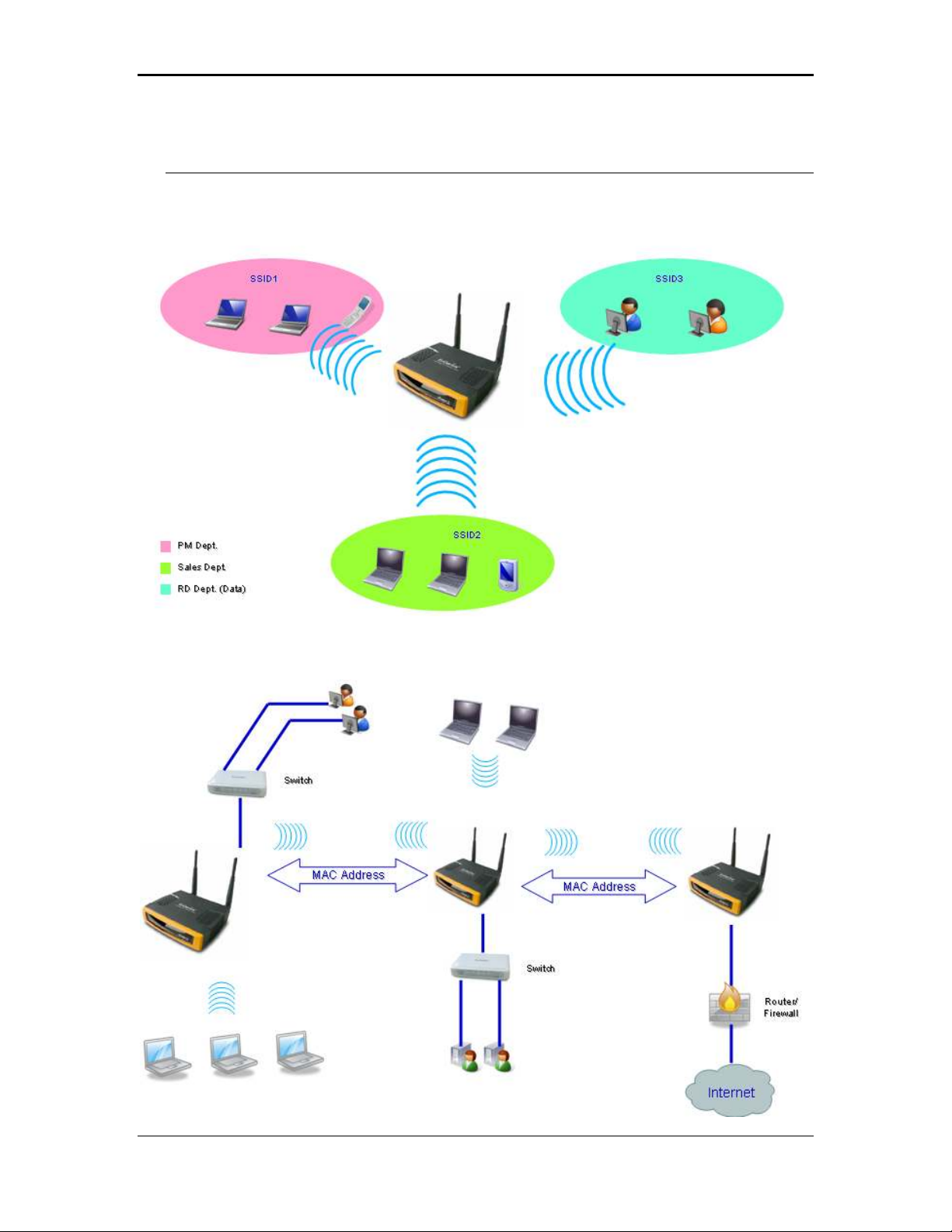
1.6 Network Configuration
To better understand how the wireless LAN products work together to create a
wireless network, it might be helpful to depict a few of the possible wireless LAN PC
card network configurations. The wireless LAN products can be configured as:
a) Ad-hoc (or peer-to-peer) for departmental or SOHO LANs.
9
Page 10
11b/g Wireless Long Range Multi-function 7+1 AP Version 1.2
b) Infrastructure for enterprise LANs.
a) Ad-hoc (peer-to-peer) Mode
This is the simplest network configuration with several computers
equipped with the PC Cards that form a wireless network whenever they
are within range of one another. In ad-hoc mode, each client is peer-topeer, would only have access to the resources of the other client and
does not require an access point. This is the easiest and least expensive
way for the SOHO to set up a wireless network. The image depicts a
network in ad-hoc mode.
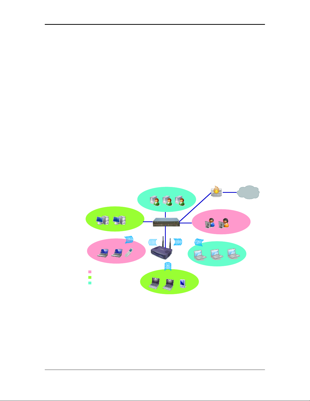
b) Infrastructure Mode
The infrastructure mode requires the use of an access point (AP). In this
mode, all wireless communication between two computers has to be via
the AP. It doesn’t matter if the AP is stand-alone or wired to an Ethernet
network. If used in stand-alone, the AP can extend the range of
independent wireless LANs by acting as a repeater, which effectively
doubles the distance between wireless stations. The image below
depicts a network in infrastructure mode.
PM Dept. (
VOIP&Data))
PM Dept. (
VOIP&Data))
PM Dept. (
VOIP&Data
PM Dept. (
VOIP&Data
Sales Dept. (
Sales Dept. (
Sales Dept. (
Sales Dept. (
RD Dept. (Data)
RD Dept. (Data)
RD Dept. (Data)
RD Dept. (Data)
VLAN2
VLAN2
VLAN2
VLAN2
SSID1
SSID1
SSID1
SSID1
VOIP&Data))
VOIP&Data))
VOIP&Data
VOIP&Data
VLAN3
VLAN3
VLAN3
VLAN3
VLAN Switch
VLAN Switch
VLAN Switch
VLAN Switch
SSID2
SSID2
SSID2
SSID2
Router/
Router/
Router/
Router/
Firewall
Firewall
Firewall
Firewall
VLAN1
VLAN1
VLAN1
VLAN1
SSID3
SSID3
SSID3
SSID3
Internet
Internet
Internet
Internet
10
Page 11

11b/g Wireless Long Range Multi-function 7+1 AP Version 1.2
11
Page 12
11b/g Wireless Long Range Multi-function 7+1 AP Version 1.2
Access Point
PC
Power Outlet
2 Understanding the Hardware
2.1 Hardware Installation
1 Place the unit in an appropriate place after conducting a site survey.
2 Plug one end of the Ethernet cable into the RJ-45 port on the rear panel of the
device and another end into your PC/Notebook.
3 Insert the DC-inlet of the power adapter into the port labeled “DC-IN” and the
other end into the power socket on the wall.
This diagram depicts the hardware configuration
3.1 IP Address Configuration
Ethernet
AC/DC cable
This device can be configured as a Bridge/Router or Access Point. The default IP
address of the device is 192.168.1.1 In order to log into this device, you must first
configure the TCP/IP settings of your PC/Notebook.
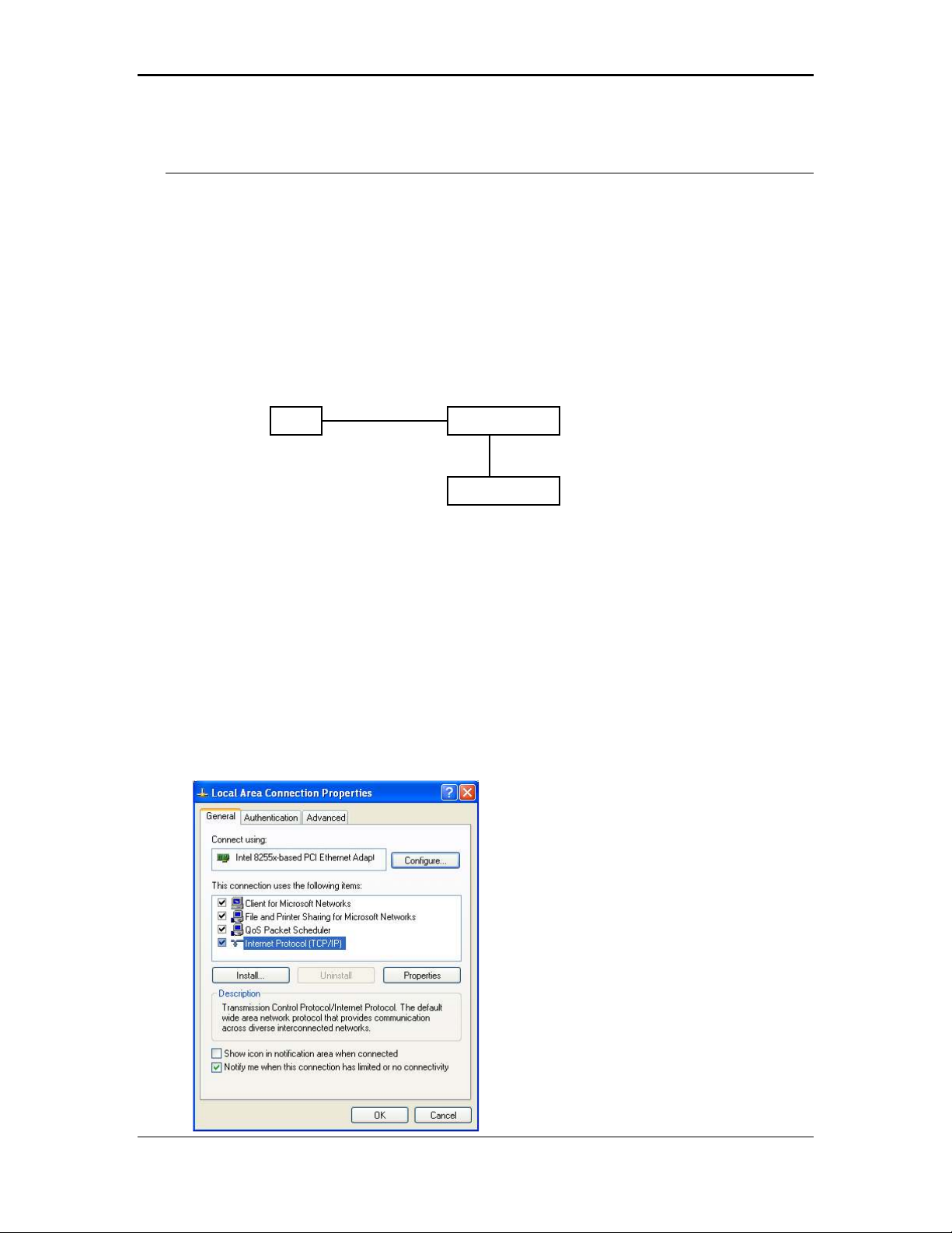
1. In the control panel, double click Network Connections and then double click on the
connection of your Network Interface Card (NIC). You will then see the following
screen.
12
Page 13
11b/g Wireless Long Range Multi-function 7+1 AP Version 1.2
2. Select Internet Protocol (TCP/IP) and then click on the Properties button. This will
allow you to configure the TCP/IP settings of your PC/Notebook.
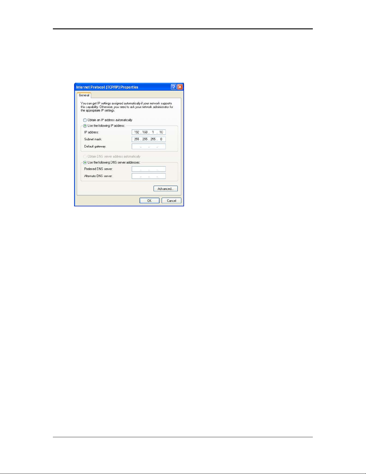
3. Select Use the following IP Address radio button and then enter the IP address
and subnet mask. Ensure that the IP address and subnet mask are on the same
subnet as the device.
For Example: Device IP address: 192.168.1.1
PC IP address: 192.168.1.10
PC subnet mask: 255.255.255.0
4. Click on the OK button to close this window, and once again to close LAN properties
window.
13
Page 14
11b/g Wireless Long Range Multi-function 7+1 AP Version 1.2
3 Switching Between Operating Modes
This device can operate in the following modes:
a) Access Point / WDS AP
b) Client Bridge
c) WDS Bridge
d) Repeater
e) AP Router
f) Client Router
This chapter will describe how to switch between operating modes.
3.1 Logging In
To configure the device through the web-browser, enter the IP address of the device
(default: 192.168.1.1) into the address bar of the web-browser and press Enter.
Make sure that the device and your computers are configured on the same subnet.
Refer to Chapter 2 in order to configure the IP address of your computer.
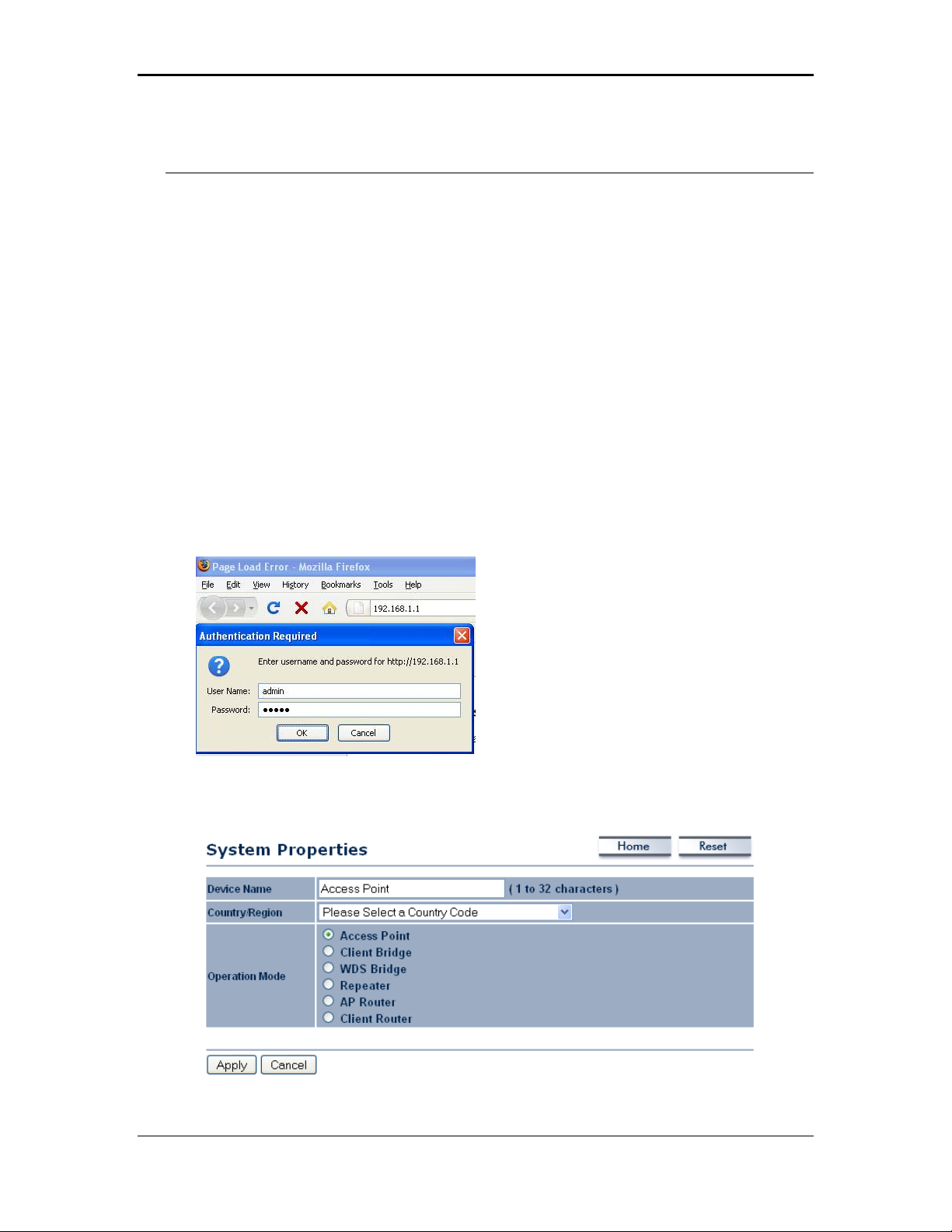
After connecting to the IP address, the web-browser will display the login page.
Specify admin for both the user name and password.
After logging in, you will see the graphical user interface of the device. Click on the
System Properties link under the System navigation drop-down menu.
14
Page 15

11b/g Wireless Long Range Multi-function 7+1 AP Version 1.2
Select and operating mode from the drop-down list and then click on the Apply
button.
15
Page 16
11b/g Wireless Long Range Multi-function 7+1 AP Version 1.2
4 Access Point / WDS Operating Mode
Access Point
WDS AP
16
Page 17
11b/g Wireless Long Range Multi-function 7+1 AP Version 1.2
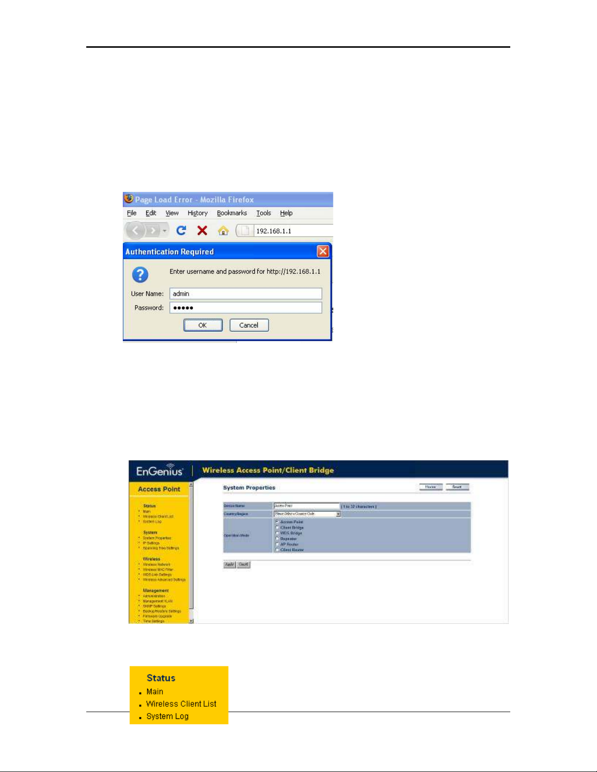
4.1 Logging In
To configure the device through the web-browser, enter the IP address of the device
(default: 192.168.1.1) into the address bar of the web-browser and press Enter.
Make sure that the device and your computers are configured on the same subnet.
Refer to Chapter 2 in order to configure the IP address of your computer.
After connecting to the IP address, the web-browser will display the login page.
Specify admin for both the user name and password.
After logging in you will graphical user interface (GUI) of the device. The navigation
drop-down menu on left is divided into four sections:
1. Status: Displays the overall status, wireless client list, and system log.
2. System: This menu includes the system properties, IP and Spanning Tree settings.
3.
Wireless: This menu includes wireless network status, MAC filter, WDS settings,
and wireless advanced settings.
Management: This menu includes the admin setup, SNMP, VLAN management,
4.
firmware upgrade, and save/restore backup.
4.2 Status
Click on the Status link on the navigation drop-
down menu. You will then see three options: Main,
17
Page 18
11b/g Wireless Long Range Multi-function 7+1 AP Version 1.2
Wireless Client List, and System Log. Each option is described in detail below.
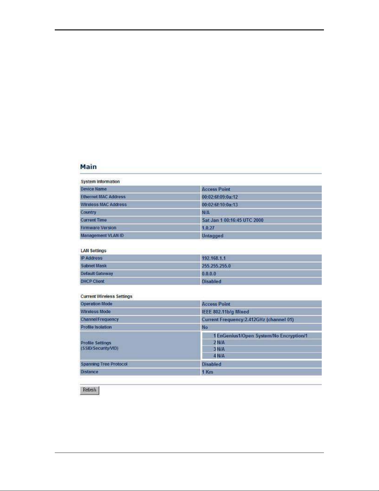
4.2.1 Main
Click on the Main link under the Status drop-down menu. The status that is
displayed corresponds with the operating mode that is selected. Information such as
operating mode, system up time, firmware version, serial number, kernel version and
application version are displayed in the ‘System’ section. LAN IP address, subnet
mask, and MAC address are displayed in the ‘LAN’ section. In the ‘Wireless section,
the frequency, channel is displayed. Since this device supports multiple-SSIDs, the
details of each SSID, such as ESSID and its security settings are displayed.
18
Page 19
11b/g Wireless Long Range Multi-function 7+1 AP Version 1.2
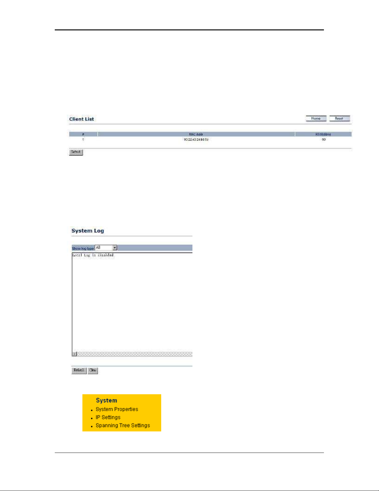
4.2.2 Wireless Client List
Click on the Wireless Client List link under the Status drop-down menu. This page
displays the list of Clients that are associated to the Access Point.
The MAC addresses and signal strength for each client is displayed. Click on the
Refresh button to refresh the client list
NOTE: You will only see the client when you have other wireless devices connected.
4.2.3 System Log
Click on the System Log link under the Status drop-down menu. The device
automatically logs (records) events of possible interest in its internal memory. If there
is not enough internal memory for all events, logs of older events are deleted, but
logs of the latest events are retained.
4.3 System
Click on the System link on the navigation
drop-down menu. You will then see three
options: System Properties, IP Settings, and
Spanning Tree Settings. Each option is
described in detail below.
19
Page 20
11b/g Wireless Long Range Multi-function 7+1 AP Version 1.2
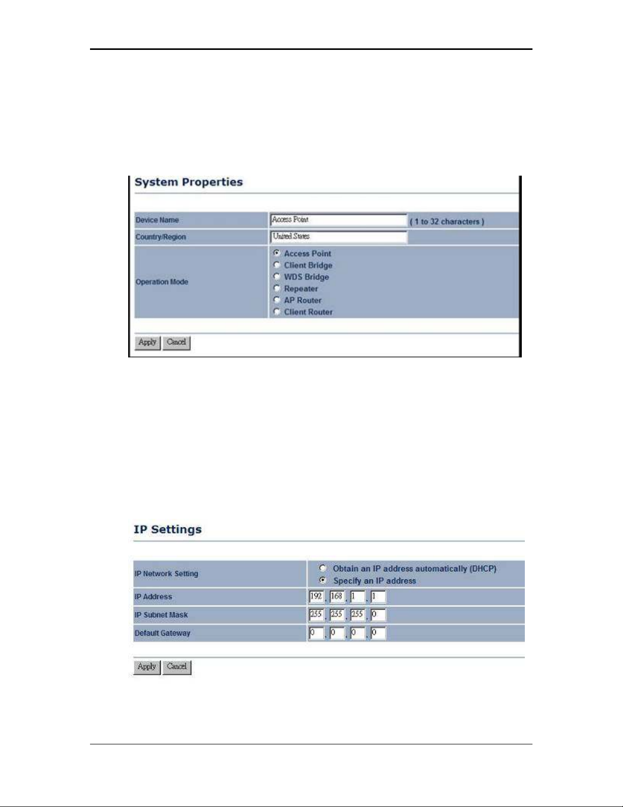
4.3.1 System Properties
Click on the System Properties link under the System drop-down menu. This page
allows you to switch the operating mode of the device, as well as specify a name and
select the operating region.
Device Name: Specify a name for the device (this is not the SSID),
Country/Region: Select a country from the drop-down list.
Operating Mode: Select and operating mode. Configuration for each operating
mode is described in their respective chapters.
Click on the Apply button to save the changes.
4.3.2 IP Settings
Click on the IP Settings link under the System drop-down menu This page allows
you to configure the device with a static IP address or a DHCP client.
IP Network Setting: Select Obtain an IP address automatically (DHCP) radio
button if the Access Point is connected to a DHCP server. This will allow the Access
Point to pass IP addresses to the clients associated with it. You may select Specify
20
Page 21
11b/g Wireless Long Range Multi-function 7+1 AP Version 1.2
an IP Address radio button if you would like the device to use a static IP address. In
this case, you would be required to specify an IP address, subnet mask, and default
gateway IP address.
IP Address: Specify an IP address
IP Subnet Mask: Specify the subnet mask for the IP address
Default Gateway: Specify the IP address of the default gateway.
Click on the Apply button to save the changes.
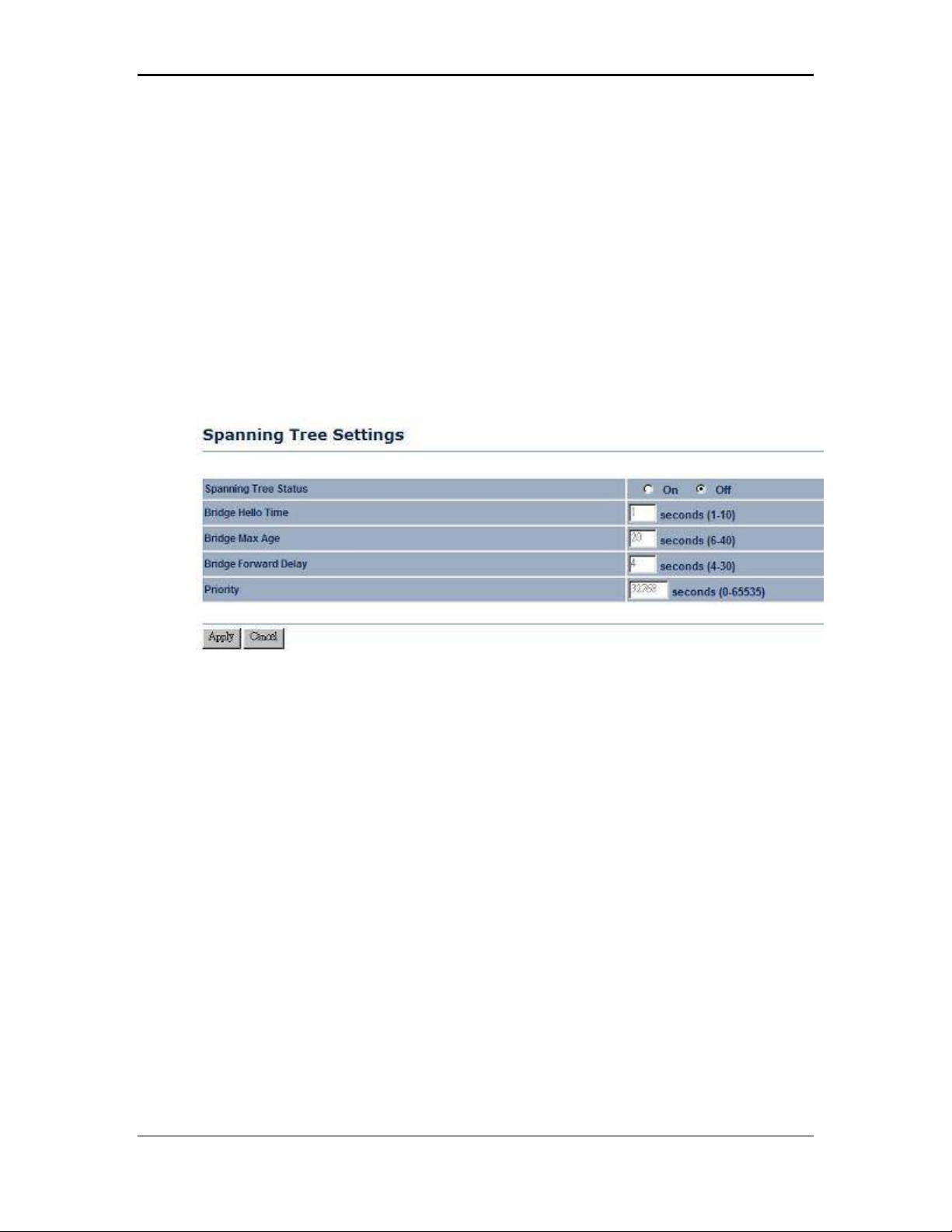
4.3.3 Spanning Tree Settings
Click on the Spanning Tree link under the System drop-down menu Spanning-Tree
Protocol is a link management protocol that provides path redundancy while
preventing undesirable loops in the network.
Spanning Tree Status: Choose to enable or disable the spanning tree feature.
Bridge Hello Time: Specify the number of seconds for the hello time.
Bridge Max Age: Specify the number of seconds for the max age.
Bridge Forward Delay: Specify the number of seconds for the bridge forward delay.
Priority: Specify the number of seconds for the priority.
Click on the Apply button to save the changes.
21
Page 22
11b/g Wireless Long Range Multi-function 7+1 AP Version 1.2
4.4 Wireless
Click on the Wireless link on the navigation
drop-down menu. You will then see four
options: wireless network, wireless MAC filter,
WDS link settings, and wireless advanced
settings. Each option is described below.
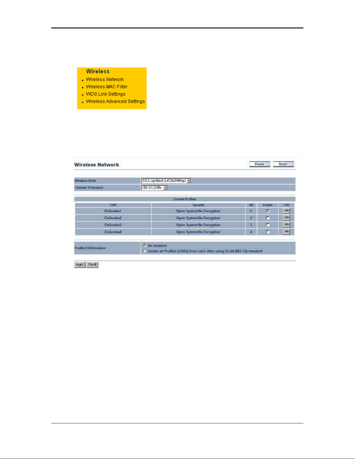
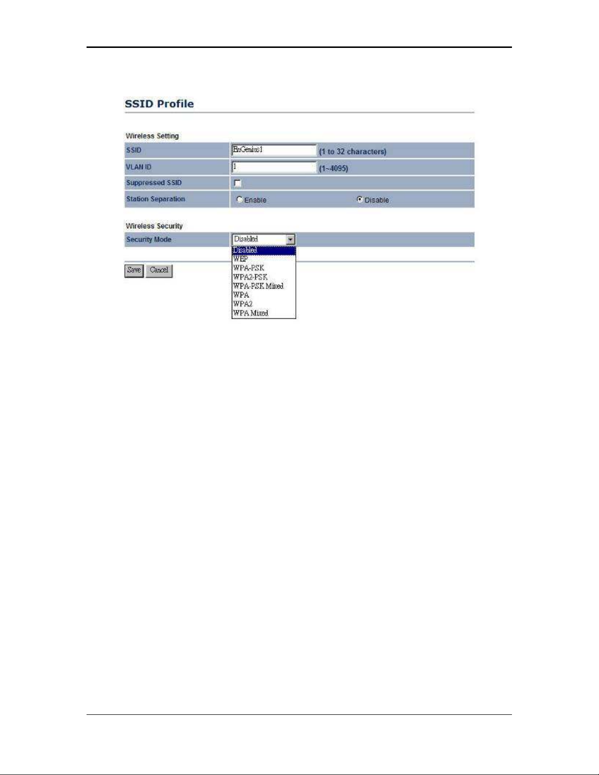
4.4.1 Wireless Network
The Wireless Network page allows you to configure the wireless mode, channel,
SSID, and security settings.
Wireless Mode: Depending on the type of wireless clients that are connected to the
network, you may select B, G, B/G-mixed and SuperG. If you are not sure about
which clients will be accessing the wireless networks, it is recommended that you
select B/G-mixed for the best performance.
Note:
In order to achieve 108Mbps data rate, you will need to check the client card is
supporting to 108Mbps as well. If your client device is not super G supported, you
can only get 54Mbps throughput only.
The AP default is set as Dynamic Super-G mode, which means if there is any nonsuper-G supported client surrounded, the AP will switch to normal G automatically.
Channel: Select a channel from the drop-down list. The channels available are
based on the country’s regulation. When selecting Infrastructure mode, a channel is
not required, however, when selecting Adhoc mode, you must select the same
channel on all points.
Current Profiles: You may configure up to four different wireless profiles. Click on
the Edit button to modify the profile and place a check in the Enable box to activate
the profile.
22
Page 23
11b/g Wireless Long Range Multi-function 7+1 AP Version 1.2
SSID: The SSID is a unique named shared amongst all the points of the wireless
network. The SSID must be identical on all points of the wireless network and cannot
exceed 32 characters.
VLAN ID: If you have enabled VLAN tagging on your network, specify the VLAN tag
ID.
Suppressed SSID: Place a check in this box if you would like to hide the SSID. By
enabling this feature, wireless clients will not be able to scan this access point in a
site survey.
Station Separation: This is also known as layer 2 isolation. Clients connected to this
Access Point will not be able to directly communicate with each other.
Security Mode: By default, the security is disabled. Refer to the next section to
configure the security features such as WEP, WPA, WPA-PSK, WPA2, WPA2-PSK
and WPA-Mixed
Click on the Apply button to save the changes.
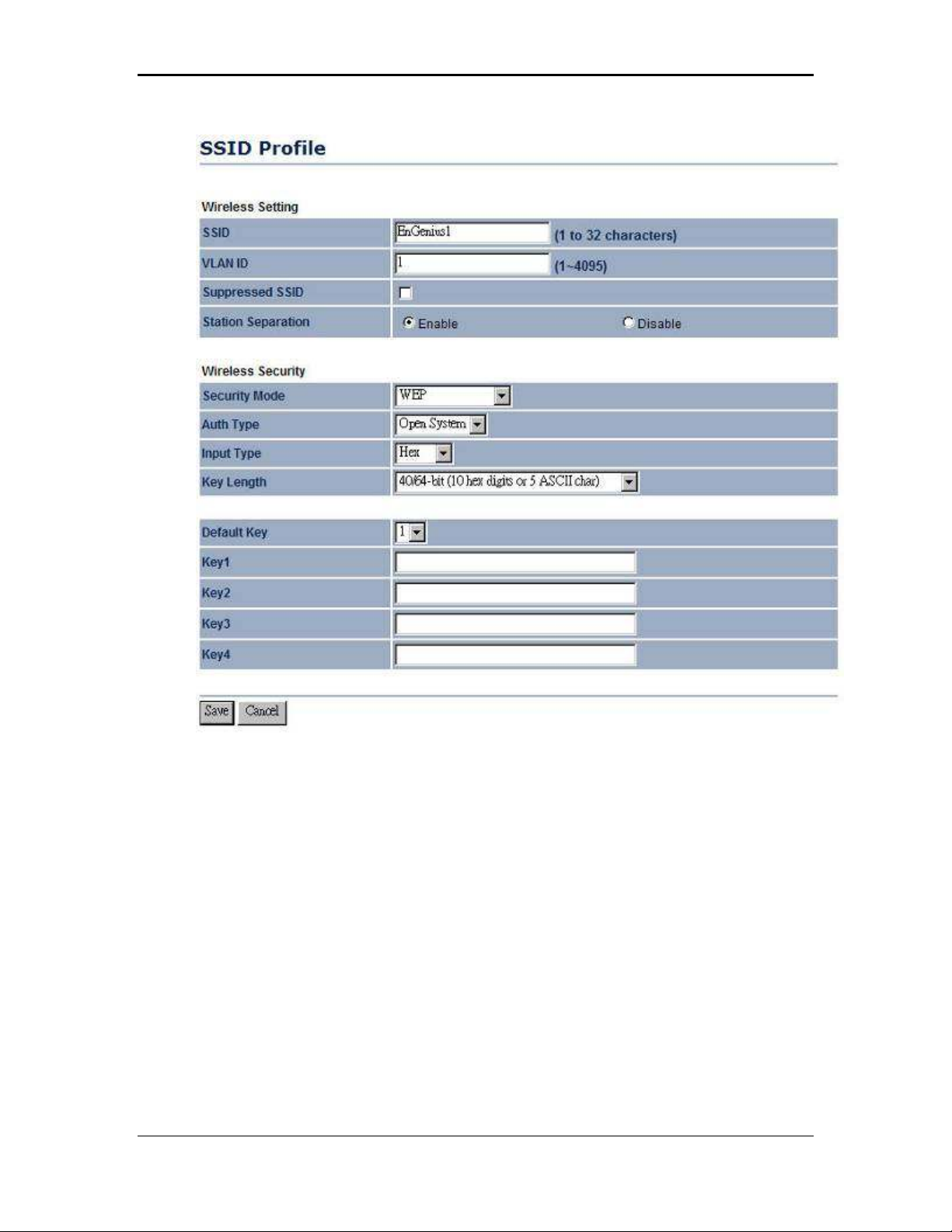
4.4.1.1 Wireless Security - WEP
Security Mode: Select WEP from the drop-down list if your wireless network uses
WEP encryption. WEP is an acronym for Wired Equivalent Privacy, and is a security
protocol that provides the same level of security for wireless networks as for a wired
network.
23
Page 24
11b/g Wireless Long Range Multi-function 7+1 AP Version 1.2
Authentication Type: Select an authentication method. Options available are Open
System, Shared Key. An open system allows any client to authenticate as long as it
conforms to any MAC address filter policies that may have been set. All
authentication packets are transmitted without encryption. Shared Key sends an
unencrypted challenge text string to any device attempting to communicate with the
Access Point. The device requesting authentication encrypts the challenge text and
sends it back to the Access Point. If the challenge text is encrypted correctly, the
Access Point allows the requesting device to authenticate. It is recommended to
select Auto if you are not sure which authentication type is used.
Input Type: Select Hex or ASCII from the drop-down list
Key Length: Select a key format from the drop-down list. 64bit-hex keys require 10
characters, where as 128-bit keys require 26 characters. A hex key is defined as a
number between 0 through 9 and letter between A through F.
Default Key: You may use up to four different keys for four different networks. Select
the current key that will be used.
Key 1-4: You may enter four different WEP keys.
Click on the Apply button to save the changes.
24
Page 25

11b/g Wireless Long Range Multi-function 7+1 AP Version 1.2
4.4.1.2 Wireless Security – WPA-PSK, WPA2-PSK, WPA-Mixed
Security Mode: Select WPA-PSK, WPA2-PSK, or WPA-Mixed from the drop-down
list if your wireless network uses WPA pre-shared key.
Encryption: Select TKIP or AES from the drop-down list if your wireless network
uses this encryption. WPA (Wi-Fi Protected Access) was designed to improve upon
the security features of WEP (Wired Equivalent Privacy). The technology is designed
to work with existing Wi-Fi products that have been enabled with WEP. WPA
provides improved data encryption through the Temporal Integrity Protocol (TKIP),
which scrambles the keys using a hashing algorithm and by adding an integrity
checking feature which makes sure that keys haven’t been tampered with.
Passphrase: Specify a passphrase that is shared amongst the Access Points and
clients.
Group Key Update Interval: Specify the number of seconds after which the Access
Point will probe the client for the passphrase.
Click on the Apply button to save the changes.
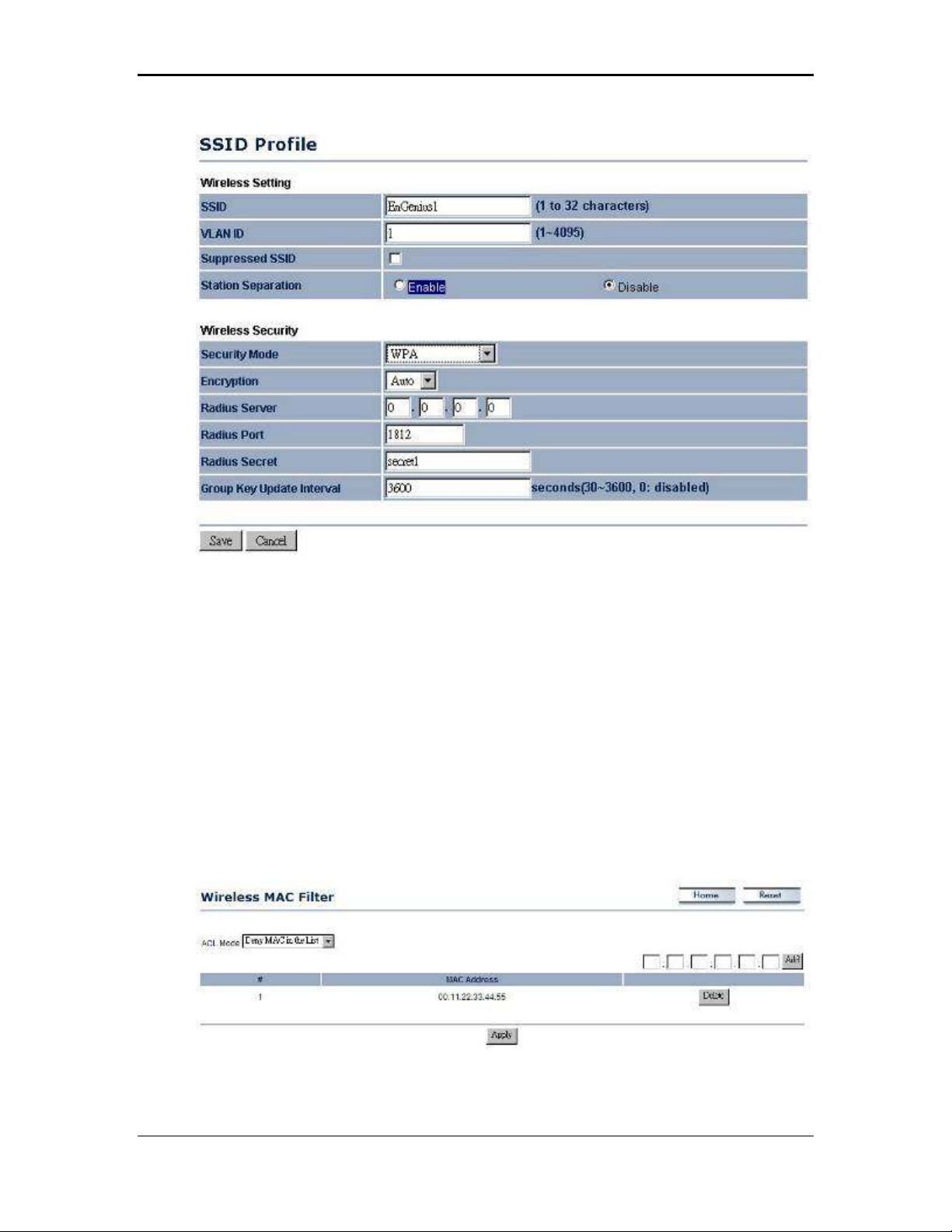
4.4.1.3 Wireless Security – WPA, WPA2
Security Mode: Select WPA or WPA2 from the drop-down list if your wireless
network uses WPA. WPA (Wi-Fi Protected Access) was designed to improve upon
the security features of WEP (Wired Equivalent Privacy). The technology is designed
to work with existing Wi-Fi products that have been enabled with WEP. WPA
provides improved data encryption through the Temporal Integrity Protocol (TKIP),
which scrambles the keys using a hashing algorithm and by adding an integrity
checking feature which makes sure that keys haven’t been tampered with.
25
Page 26
11b/g Wireless Long Range Multi-function 7+1 AP Version 1.2
Encryption: Select TKIP or AES from the drop-down list if your wireless network
uses this encryption.
RADIUS IP Address: Enter the IP address of the RADIUS server.
RADIUS Port: Enter the port number of the RADIUS server. The default is usually
1812.
RADIUS Secret: Enter the shared password of the RADIUS server.
Group Key Update Interval: Specify the number of seconds after which the Access
Point will probe the client for the secret.
Click on the Apply button to save the changes.
4.4.2 Wireless MAC Filter
Click on the Wireless MAC Filter link under the Wireless menu. On this page you
can filter the MAC address by allowing or blocking access the network.
ACL (Access Control) Mode: You may choose to Disable, Allow Listed, or Deny
Listed MAC addresses from associating with the network. By selecting Allow MAC
in the List, only the address listed in the table will have access to the network; all
26
Page 27
11b/g Wireless Long Range Multi-function 7+1 AP Version 1.2
other clients will be blocked. On the other hand, selected Deny MAC in the List,
only the listed MAC addresses will be blocked from accessing the network; all other
clients will have access to the network.
MAC Address: Enter the MAC address.
This table lists the blocked or allowed MAC addresses; you may delete selected
MAC address or delete all the addresses from the table by clicking on the Delete
button.
Click on the Apply button to save the changes.
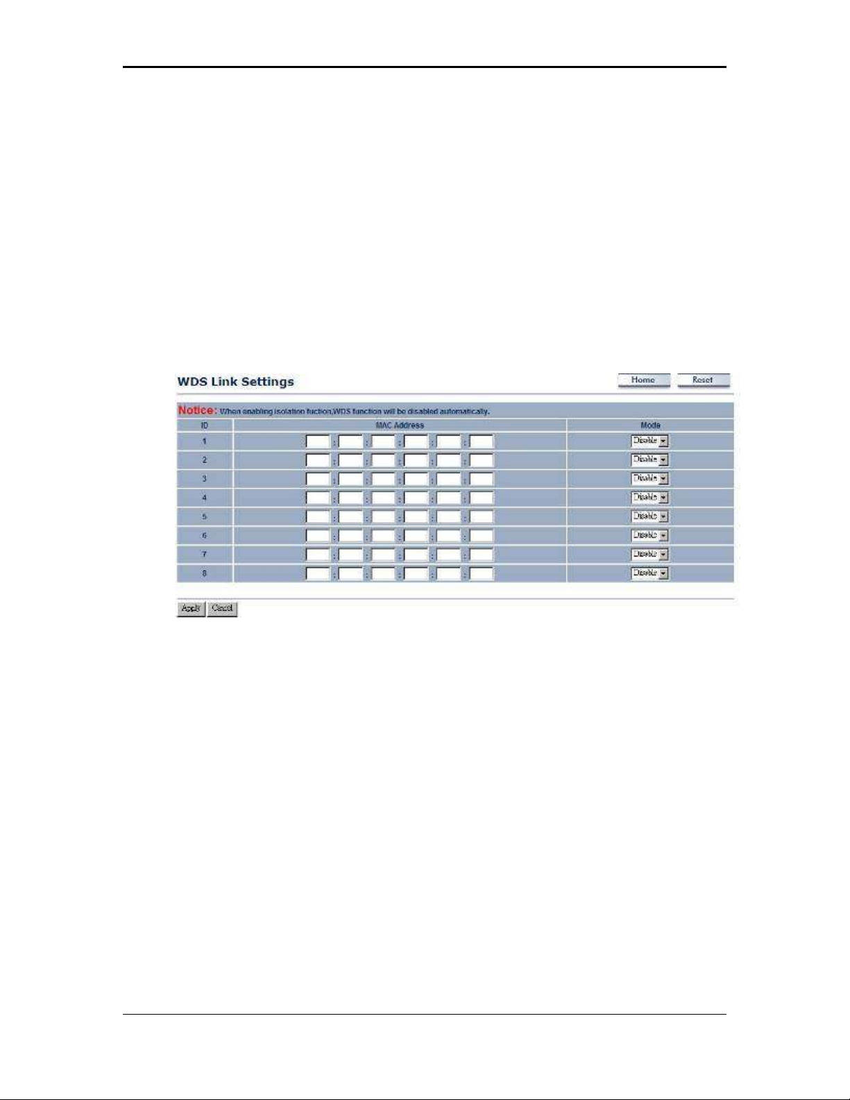
4.4.3 WDS Link Settings
Click on the WDS Link Settings On this page you can configure the WDS (Wireless
Distribution System) which allows the Access Point to function as a repeater.
WDS MAC Address: Specify the MAC address of the Access Points that will join the
WDS network and then select Enable or Disable from the drop-down list.
Click on the Apply button to save the changes.
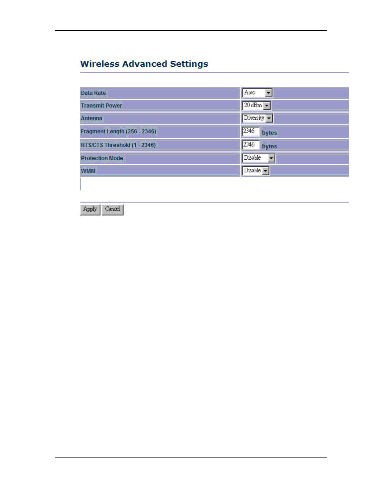
4.4.4 Wireless Advanced Settings
Click on the Wireless Advanced Settings link. On this page you can configure the
advanced settings to tweak the performance of your wireless network. Options
available are: data rate, transmit power, antenna diversity, fragmentation threshold,
RTS threshold, 802.11g protection and distance.
27
Page 28
11b/g Wireless Long Range Multi-function 7+1 AP Version 1.2
Data Rate: If you would like to force a data rate, you may select one from the drop-
down list. However, for best performance it is recommended to use the Auto setting.
Transmit Power: You may have the different application distance of the device by
selecting a value from the drop-down list. This feature can be helpful in restricting the
coverage area of the wireless network.
Antenna:
Fragment: Packets over the specified size will be fragmented in order to improve
performance on noisy networks.
RTS Threshold: Packets over the specified size will use the RTS/CTS mechanism to
maintain performance in noisy networks and preventing hidden nodes from
degrading the performance.
Protection Mode: If your wireless network is using both 802.11b and 802.g devices
then it is recommended to enable this feature so that the 802.11b devices will not
degrade the performance of 802.11g devices.
WMM: Choose to enable or disable wireless multimedia mode.
Click on the Apply button to save the changes.
28
Page 29
11b/g Wireless Long Range Multi-function 7+1 AP Version 1.2
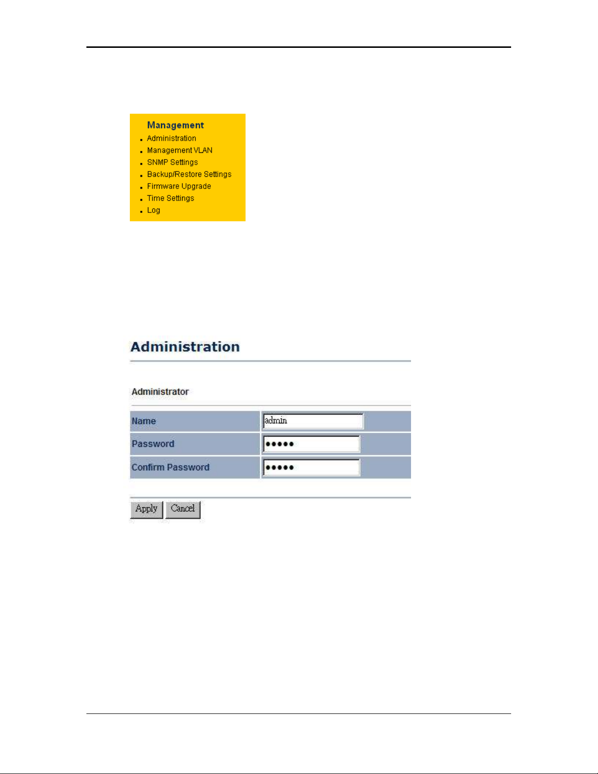
4.5 Management
Click on the Management link on the
navigation drop-down menu. You will then see
seven options: administration, management
VLAN, SNMP settings, backup/restore
settings, firmware upgrade, time settings, and
log. Each option is described below.
4.5.1 Administration
Click on the Administration link under the Management menu. This option allows
you to create a user name and password for the device. By default, this device is
configured without a user name and password admin. For security reasons it is
highly recommended that you create a new user name and password.
Name: Specify a user name into the first field.
Password: Specify a password into this field and then re-type the password into the
Confirm Password field.
Click on the Apply button to save the changes.
29
Page 30
11b/g Wireless Long Range Multi-function 7+1 AP Version 1.2
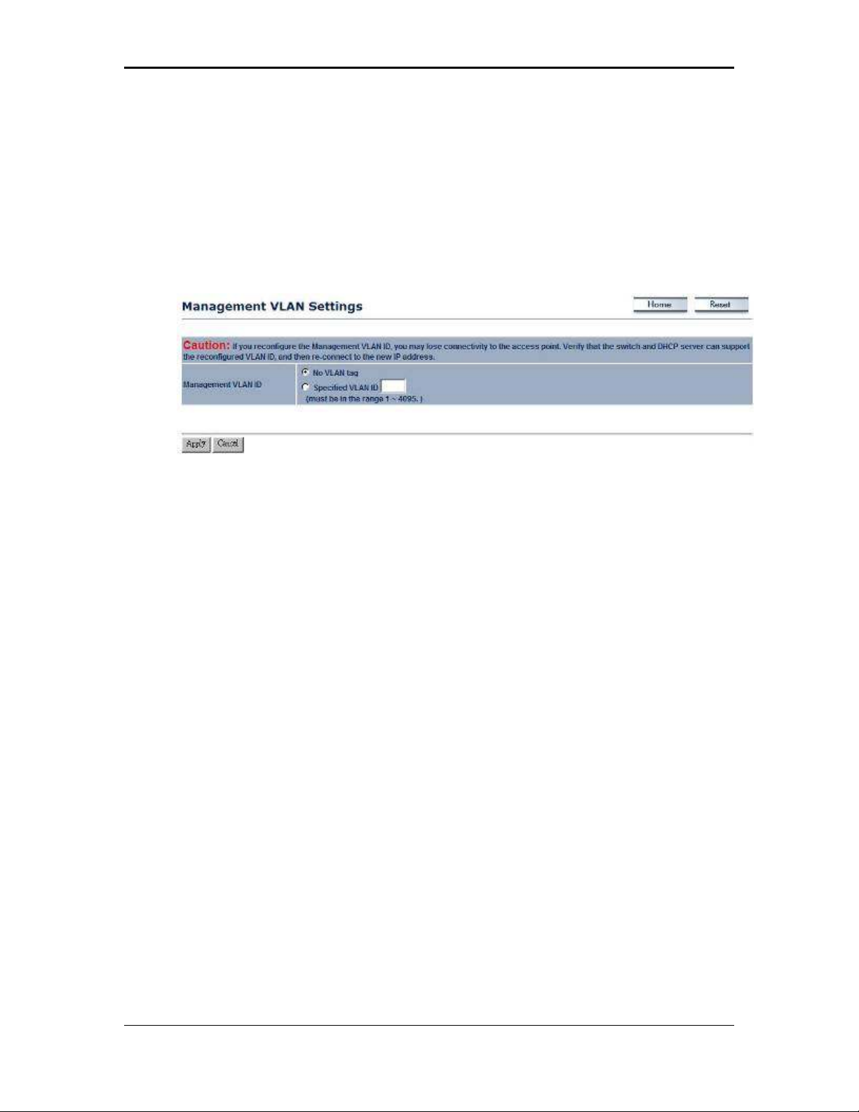
4.5.2 Management VLAN
Click on the SNMP link under the Management menu. This option allows you to
assign a VLAN tag to the packets. A VLAN is a group of computers on a network
whose software has been configured so that they behave as if they were on a
separate Local Area Network (LAN). Computers on VLAN do not have to be
physically located next to one another on the LAN
Management VLAN ID: If your network includes VLANs and if tagged packets need
to pass through the Access Point, specify the VLAN ID into this field. If not, select the
No VLAN tag radio button.
Note: If your reconfigure the Management VLAN ID, you may lose connectivity to the
Access Point. Verify that the switch and DHCP server can support the reconfigured
VLAN ID, and then re-connect to the new IP address.
Click on the Apply button to save the changes.
4.5.3 SNMP Settings
Click on the SNMP Settings link under the Management menu. This option allows
you to assign the contact details, location, community name and trap settings for
SNMP. This is a networking management protocol used to monitor network-attached
devices. SNMP allows messages (called protocol data units) to be sent to various
parts of a network. Upon receiving these messages, SNMP-compatible devices
(called agents) return data stored in their Management Information Bases. .
30
Page 31

11b/g Wireless Long Range Multi-function 7+1 AP Version 1.2
SNMP Enable/Disable: Choose to enable or disable the SNMP feature.
Contact: Specify the contact details of the device.
Location: Specify the location of the device.
Read-Only Community Name: Specify the password for access the SNMP
community for read only access.
Read-Write Community Name: Specify the password for access to the SNMP
community with read/write access.
Trap Destination IP Address: Specify the IP address of the computer that will
receive the SNMP traps.
Trap Destination Community Name: Specify the password for the SNMP trap
community.
Click on the Apply button to save the changes.
4.5.4 Backup/Restore settings, Reset to factory default settings
Click on the Backup/Restore Setting link under the Management menu. This option
is used to save the current settings of the device in a file on your local disk or load
settings on to the device from a local disk. This feature is very handy for
administrators who have several devices that need to be configured with the same
settings.
31
Page 32

11b/g Wireless Long Range Multi-function 7+1 AP Version 1.2
Save a copy of the current settings: Click on the Backup button to save the current
configuration.
Restore saved settings from a file: Once a file has been backed up, you may
restore it by clicking on the Browse button to select the file, and then the Restore
button.
Revert to factory default settings: Click on the Factory Default Settings button to
reset the device to the default settings. Please wait while the device restart and then
access the device using the default IP address: 192.168.1.1
4.5.5 Firmware Upgrade
Click on the Upgrade Firmware link under the Management menu. This page is
used to upgrade the firmware on the device. Make sure that downloaded the
appropriate firmware from your vendor.
Click on the Browse button and then select the appropriate firmware and then click
on the Upgrade button.
Note: The upgrade process may take about 1 minute to complete. Do not power off
the device during this process as it may crash the device and make it unusable. The
device will restart automatically once the upgrade is complete.
32
Page 33

11b/g Wireless Long Range Multi-function 7+1 AP Version 1.2
4.5.6 Time Settings
Click on the Time Settings link under the Management menu. This page allows you
to configure the time on the device. You may do this manually or by connecting to a
NTP server.
Manually Set Date and Time: Specify the date and time
Automatically Get Date and Time: Select the time zone from the drop down list and
then specify the IP address of the NTP server.
Click on the Apply button to save the changes.
4.5.7 Log
Click on the Log link under the Management menu. The Log page displays a list of
events that are triggered on the Ethernet and Wireless interface. This log can be
referred when an unknown error occurs on the system or when a report needs to be
sent to the technical support department for debugging purposes.
Syslog: Choose to enable or disable the system log.
Log Server IP Address: Specify the IP address of the server that will receive the
system log.
Local Log: Choose to enable or disable the local log.
Click on the Apply button to save the changes.
33
Page 34

11b/g Wireless Long Range Multi-function 7+1 AP Version 1.2
5 Client Bridge Operating Mode
5.1 Logging In
To configure the device through the web-browser, enter the IP address of the device
(default: 192.168.1.1) into the address bar of the web-browser and press Enter.
Make sure that the device and your computers are configured on the same subnet.
Refer to Chapter 2 in order to configure the IP address of your computer.
After connecting to the IP address, the web-browser will display the login page.
Specify admin for both the user name and password.
34
Page 35

11b/g Wireless Long Range Multi-function 7+1 AP Version 1.2
After logging in you will graphical user interface (GUI) of the device. The navigation
drop-down menu on left is divided into four sections:
1. Status: Displays the overall status, connection status, and event log.
2. System: This menu includes the system properties, IP and Spanning Tree settings.
3.
Wireless: This menu includes status, basic, advanced, and security.
Management: This menu includes the admin setup, SNMP, VLAN management,
4.
firmware upgrade, and save/restore backup.
5.2 Status
Click on the Status link on the navigation
drop-down menu. You will then see three
options: Main, Connection Status, and System
Log. Each option is described in detail below.
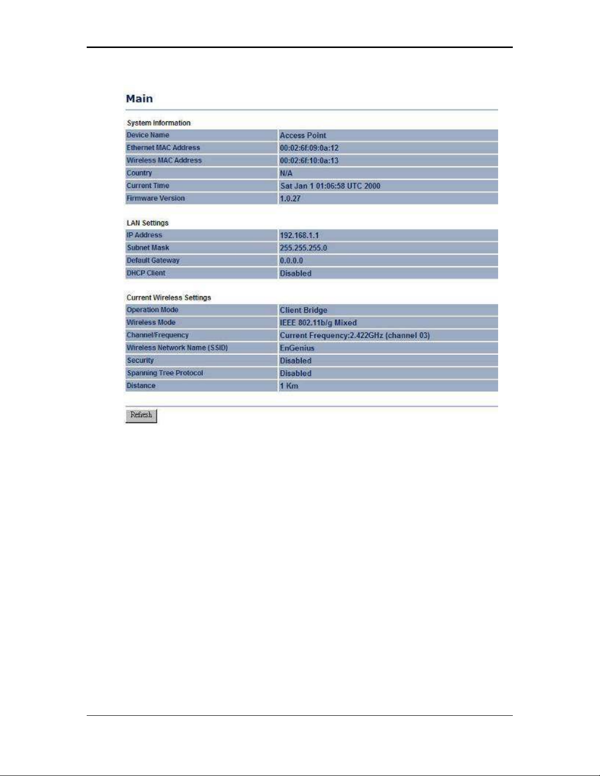
5.2.1 Main
Click on the Main link under the Status drop-down menu. The status that is
displayed corresponds with the operating mode that is selected. Information such as
operating mode, system up time, firmware version, serial number, kernel version and
application version are displayed in the ‘System’ section. LAN IP address, subnet
mask, and MAC address are displayed in the ‘LAN’ section. In the ‘Wireless section,
the frequency, channel is displayed. Since this device supports multiple-SSIDs, the
details of each SSID, such as ESSID and its security settings are displayed.
35
Page 36
11b/g Wireless Long Range Multi-function 7+1 AP Version 1.2
5.2.2 Connection Status
Click on the Connection Status link under the Status drop-down menu. This page
displays the current status of the network, including network type, SSID, BSSID,
connection status, wireless mode, current channel, security, data rate, noise level
and signal strength.
36
Page 37

11b/g Wireless Long Range Multi-function 7+1 AP Version 1.2
5.2.3 System Log
Click on the System Log link under the Status drop-down menu. The device
automatically logs (records) events of possible interest in its internal memory. If there
is not enough internal memory for all events, logs of older events are deleted, but
logs of the latest events are retained.
37
Page 38

11b/g Wireless Long Range Multi-function 7+1 AP Version 1.2
5.3 System
Click on the System link on the navigation
drop-down menu. You will then see three
options: System Properties, IP Settings, and
Spanning Tree Settings. Each option is
described in detail below.
5.3.1 System Properties
Click on the System Properties link under the System drop-down menu. This page
allows you to switch the operating mode of the device, as well as specify a name and
select the operating region.
Device Name: Specify a name for the device (this is not the SSID),
Country/Region: Select a country from the drop-down list.
Operating Mode: Select and operating mode. Configuration for each operating
mode is described in their respective chapters.
Click on the Apply button to save the changes.
5.3.2 IP Settings
Click on the IP Settings link under the System drop-down menu This page allows
you to configure the device with a static IP address or a DHCP client.
38
Page 39

11b/g Wireless Long Range Multi-function 7+1 AP Version 1.2
IP Network Setting: Select Obtain an IP address automatically (DHCP) radio
button if the Access Point is connected to a DHCP server. This will allow the Access
Point to pass IP addresses to the clients associated with it. You may select Specify
an IP Address radio button if you would like the device to use a static IP address. In
this case, you would be required to specify an IP address, subnet mask, and default
gateway IP address.
IP Address: Specify an IP address
IP Subnet Mask: Specify the subnet mask for the IP address
Default Gateway: Specify the IP address of the default gateway.
Click on the Apply button to save the changes.
5.3.3 Spanning Tree Settings
Click on the Spanning Tree link under the System drop-down menu Spanning-Tree
Protocol is a link management protocol that provides path redundancy while
preventing undesirable loops in the network.
Spanning Tree Status: Choose to enable or disable the spanning tree feature.
Bridge Hello Time: Specify the number of seconds for the hello time.
Bridge Max Age: Specify the number of seconds for the max age.
Bridge Forward Delay: Specify the number of seconds for the bridge forward delay.
Priority: Specify the number of seconds for the priority.
39
Page 40

11b/g Wireless Long Range Multi-function 7+1 AP Version 1.2
Click on the Apply button to save the changes.
40
Page 41

11b/g Wireless Long Range Multi-function 7+1 AP Version 1.2
5.4 Wireless
Click on the Wireless link on the
navigation drop-down menu. You will
then see three options: wireless
network, wireless security, and wireless
advanced settings. Each option is
described below.
5.4.1 Wireless Network
The Wireless Network page allows you to configure the wireless mode, channel,
SSID, and security settings.
Wireless Mode: Depending on the type of wireless clients that are connected to the
network, you may select B, G, or B/G-mixed. If you are not sure about which clients
will be accessing the wireless networks, it is recommended that you select B/G-
mixed for the best performance.
SSID: The SSID is a unique named shared amongst all the points of the wireless
network. The SSID must be identical on all points of the wireless network and cannot
exceed 32 characters. You may specify an SSID or select one from the Site Survey.
Site Survey: Click on the Site Survey button in order to scan the 2.4GHz frequency
for devices that broadcast their SSID. Click on the BSSID link to connect to the
Access Point. Click on the Refresh button to re-scan the frequency.
Prefer BSSID
WDS Support
41
Page 42

11b/g Wireless Long Range Multi-function 7+1 AP Version 1.2
5.4.2 Wireless Security - WEP
Security Mode: Select WEP from the drop-down list if your wireless network uses
WEP encryption. WEP is an acronym for Wired Equivalent Privacy, and is a security
protocol that provides the same level of security for wireless networks as for a wired
network.
Authentication Type: Select an authentication method. Options available are Open
System, Shared Key or Auto. An open system allows any client to authenticate as
long as it conforms to any MAC address filter policies that may have been set. All
authentication packets are transmitted without encryption. Shared Key sends an
unencrypted challenge text string to any device attempting to communicate with the
Access Point. The device requesting authentication encrypts the challenge text and
sends it back to the Access Point. If the challenge text is encrypted correctly, the
Access Point allows the requesting device to authenticate. It is recommended to
select Auto if you are not sure which authentication type is used.
Input Type: Select He or ASCII from the drop-down list
42
Page 43

11b/g Wireless Long Range Multi-function 7+1 AP Version 1.2
Key Length: Select a key format from the drop-down list. 64bit-hex keys require 10
characters, where as 128-bit keys require 26 characters. A hex key is defined as a
number between 0 through 9 and letter between A through F.
Default Key: You may use up to four different keys for four different networks. Select
the current key that will be used.
Key 1-4: You may enter four different WEP keys.
Click on the Apply button to save the changes.
5.4.3 Wireless Security – WPA-PSK, WPA2-PSK,
Security Mode: Select WPA-PSK, or WPA2-PSK from the drop-down list if your
wireless network uses WPA pre-shared key.
Encryption: Select TKIP or AES from the drop-down list if your wireless network
uses this encryption. WPA (Wi-Fi Protected Access) was designed to improve upon
the security features of WEP (Wired Equivalent Privacy). The technology is designed
to work with existing Wi-Fi products that have been enabled with WEP. WPA
provides improved data encryption through the Temporal Integrity Protocol (TKIP),
which scrambles the keys using a hashing algorithm and by adding an integrity
checking feature which makes sure that keys haven’t been tampered with.
Passphrase: Specify a passphrase that is shared amongst the Access Points and
clients.
Click on the Apply button to save the changes.
5.4.4 Wireless Advanced Settings
Click on the Wireless Advanced Settings link. On this page you can configure the
advanced settings to tweak the performance of your wireless network. Options
available are: data rate, transmit power, antenna diversity, fragmentation threshold,
RTS threshold, 802.11g protection and distance.
43
Page 44

11b/g Wireless Long Range Multi-function 7+1 AP Version 1.2
Data Rate: If you would like to force a data rate, you may select one from the drop-
down list. However, for best performance it is recommended to use the Auto setting.
Transmit Power: You may have the different application distance of the device by
selecting a value from the drop-down list. This feature can be helpful in restricting the
coverage area of the wireless network.
Antenna:
Fragment: Packets over the specified size will be fragmented in order to improve
performance on noisy networks.
RTS Threshold: Packets over the specified size will use the RTS/CTS mechanism to
maintain performance in noisy networks and preventing hidden nodes from
degrading the performance.
Protection Mode: If your wireless network is using both 802.11b and 802.g devices
then it is recommended to enable this feature so that the 802.11b devices will not
degrade the performance of 802.11g devices.
WMM: Choose to enable or disable wireless multimedia mode.
Click on the Apply button to save the changes.
5.5 Management
Click on the Management link on the
navigation drop-down menu. You will then
see six options: administration, SNMP
settings, backup/restore settings, firmware
upgrade, time settings, and log. Each option
is described below.
44
Page 45

11b/g Wireless Long Range Multi-function 7+1 AP Version 1.2
5.5.1 Administration
Click on the Administration link under the Management menu. This option allows
you to create a user name and password for the device. By default, this device is
configured without a user name and password admin. For security reasons it is
highly recommended that you create a new user name and password.
Name: Specify a user name into the first field.
Password: Specify a password into this field and then re-type the password into the
Confirm Password field.
Click on the Apply button to save the changes.
5.5.2 SNMP Settings
Click on the SNMP Settings link under the Management menu. This option allows
you to assign the contact details, location, community name and trap settings for
SNMP. This is a networking management protocol used to monitor network-attached
devices. SNMP allows messages (called protocol data units) to be sent to various
parts of a network. Upon receiving these messages, SNMP-compatible devices
(called agents) return data stored in their Management Information Bases. .
45
Page 46

11b/g Wireless Long Range Multi-function 7+1 AP Version 1.2
SNMP Enable/Disable: Choose to enable or disable the SNMP feature.
Contact: Specify the contact details of the device.
Location: Specify the location of the device.
Read-Only Community Name: Specify the password for access the SNMP
community for read only access.
Read-Write Community Name: Specify the password for access to the SNMP
community with read/write access.
Send SNMP Trap: Specify the IP address of the computer that will receive the
SNMP traps.
Trap Community Name: Specify the password for the SNMP trap community.
Click on the Apply button to save the changes.
5.5.3 Backup/Restore settings, Reset to factory default settings
Click on the Backup/Restore Setting link under the Management menu. This option
is used to save the current settings of the device in a file on your local disk or load
settings on to the device from a local disk. This feature is very handy for
administrators who have several devices that need to be configured with the same
settings.
46
Page 47

11b/g Wireless Long Range Multi-function 7+1 AP Version 1.2
Save a copy of the current settings: Click on the Backup button to save the current
configuration.
Restore saved settings from a file: Once a file has been backed up, you may
restore it by clicking on the Browse button to select the file, and then the Restore
button.
Revert to factory default settings: Click on the Factory Default Settings button to
reset the device to the default settings. Please wait while the device restart and then
access the device using the default IP address: 192.168.1.1
5.5.4 Firmware Upgrade
Click on the Upgrade Firmware link under the Management menu. This page is
used to upgrade the firmware on the device. Make sure that downloaded the
appropriate firmware from your vendor.
Click on the Browse button and then select the appropriate firmware and then click
on the Upgrade button.
Note: The upgrade process may take about 1 minute to complete. Do not power off
the device during this process as it may crash the device and make it unusable. The
device will restart automatically once the upgrade is complete.
5.5.5 Time Settings
Click on the Time Settings link under the Management menu. This page allows you
to configure the time on the device. You may do this manually or by connecting to a
NTP server.
47
Page 48

11b/g Wireless Long Range Multi-function 7+1 AP Version 1.2
Manually Set Date and Time: Specify the date and time
Automatically Get Date and Time: Select the time zone from the drop down list and
then specify the IP address of the NTP server.
Click on the Apply button to save the changes.
5.5.6 Log
Click on the Log link under the Management menu. The Log page displays a list of
events that are triggered on the Ethernet and Wireless interface. This log can be
referred when an unknown error occurs on the system or when a report needs to be
sent to the technical support department for debugging purposes.
Syslog: Choose to enable or disable the system log.
Log Server IP Address: Specify the IP address of the server that will receive the
system log.
Local Log: Choose to enable or disable the local log.
Click on the Apply button to save the changes.
48
Page 49

11b/g Wireless Long Range Multi-function 7+1 AP Version 1.2
6 WDS Bridge Operating Mode
6.1 Logging In
To configure the device through the web-browser, enter the IP address of the device
(default: 192.168.1.1) into the address bar of the web-browser and press Enter.
Make sure that the device and your computers are configured on the same subnet.
Refer to Chapter 2 in order to configure the IP address of your computer.
After connecting to the IP address, the web-browser will display the login page.
Specify admin for both the user name and password.
After logging in you will graphical user interface (GUI) of the device. The navigation
drop-down menu on left is divided into four sections:
1. Status: Displays the overall status, WDS link status, and system log.
49
Page 50

11b/g Wireless Long Range Multi-function 7+1 AP Version 1.2
2. System: This menu includes the system properties.
3.
Wireless: This menu includes status, basic, WDS link settings, WDS security, and
wireless advanced settings.
Management: This menu includes the admin setup, SNMP, firmware upgrade, time
4.
settings, logs, and save/restore backup
y
6.2 Status
Click on the Status link on the navigation
drop-down menu. You will then see three
options: Main, WDS Link Status, and System
Log. Each option is described in detail below.
6.2.1 Main
Click on the Main link under the Status drop-down menu. The status that is
displayed corresponds with the operating mode that is selected. Information such as
operating mode, system up time, firmware version, serial number, kernel version and
application version are displayed in the ‘System’ section. LAN IP address, subnet
mask, and MAC address are displayed in the ‘LAN’ section. In the ‘Wireless section,
the frequency, channel is displayed. Since this device supports multiple-SSIDs, the
details of each SSID, such as ESSID and its security settings are displayed.
50
Page 51

11b/g Wireless Long Range Multi-function 7+1 AP Version 1.2
6.2.2 WDS Link Status
Click on the WDS Link Status link under the Status drop-down menu. This page
displays the current status of WDS link, including station ID, MAC address, status
and RSSI.
6.2.3 System Log
Click on the System Log link under the Status drop-down menu. The device
automatically logs (records) events of possible interest in its internal memory. If there
is not enough internal memory for all events, logs of older events are deleted, but
logs of the latest events are retained.
51
Page 52
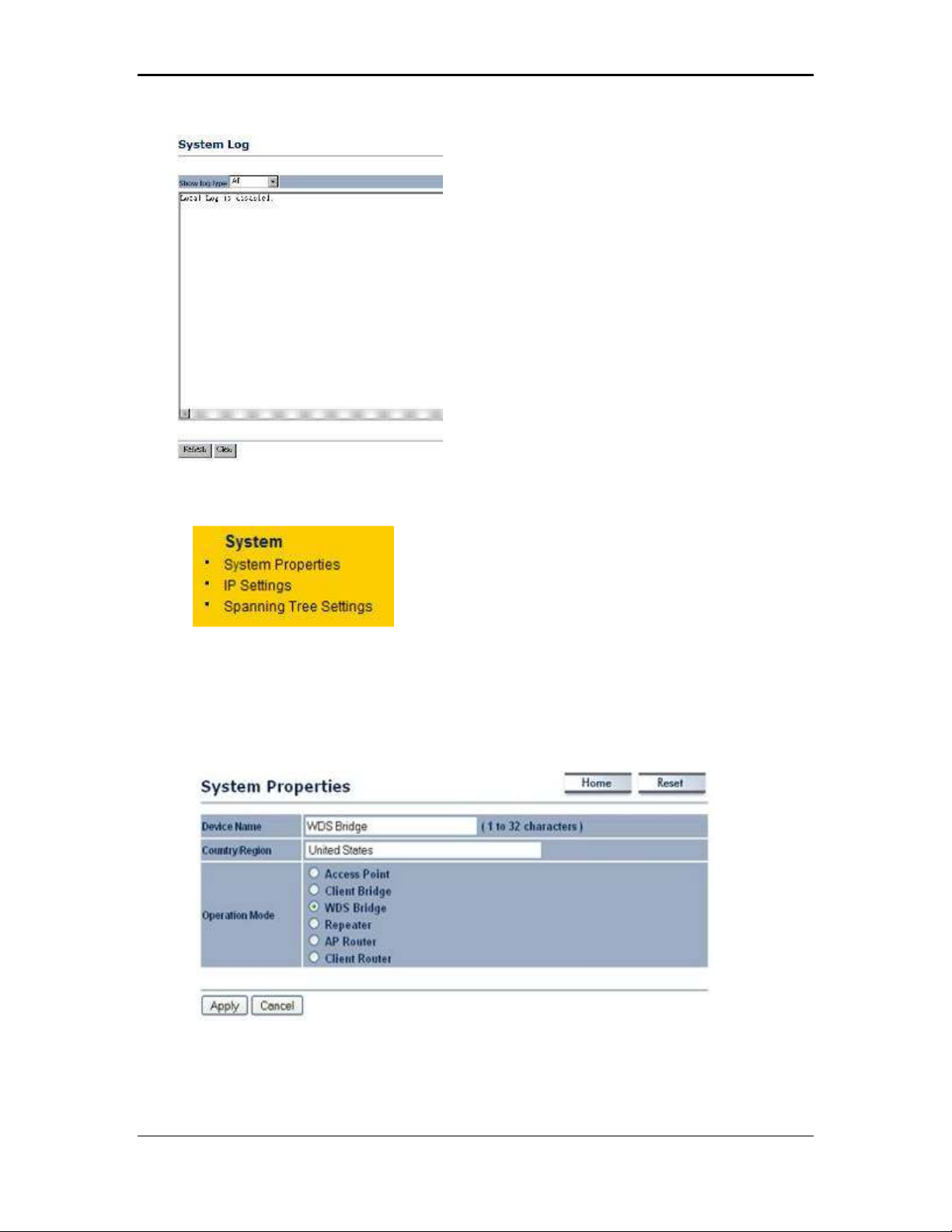
11b/g Wireless Long Range Multi-function 7+1 AP Version 1.2
6.3 System
Click on the System link on the navigation
drop-down menu. You will then see
System Properties setting, which is
described below.
6.3.1 System Properties
Click on the System Properties link under the System drop-down menu. This page
allows you to switch the operating mode of the device, as well as specify a name and
select the operating region.
Device Name: Specify a name for the device (this is not the SSID),
Country/Region: Select a country from the drop-down list.
Operating Mode: Select and operating mode. Configuration for each operating
mode is described in their respective chapters.
52
Page 53

11b/g Wireless Long Range Multi-function 7+1 AP Version 1.2
Click on the Apply button to save the changes.
6.3.2 IP Settings
Click on the IP Settings link under the System drop-down menu This page allows
you to configure the device with a static IP address or a DHCP client.
IP Network Setting: Select Obtain an IP address automatically (DHCP) radio
button if the Access Point is connected to a DHCP server. This will allow the Access
Point to pass IP addresses to the clients associated with it. You may select Specify
an IP Address radio button if you would like the device to use a static IP address. In
this case, you would be required to specify an IP address, subnet mask, and default
gateway IP address.
IP Address: Specify an IP address
IP Subnet Mask: Specify the subnet mask for the IP address
Default Gateway: Specify the IP address of the default gateway.
Click on the Apply button to save the changes.
53
Page 54

11b/g Wireless Long Range Multi-function 7+1 AP Version 1.2
6.3.3 Spanning Tree Settings
Click on the Spanning Tree link under the System drop-down menu Spanning-Tree
Protocol is a link management protocol that provides path redundancy while
preventing undesirable loops in the network.
Spanning Tree Status: Choose to enable or disable the spanning tree feature.
Bridge Hello Time: Specify the number of seconds for the hello time.
Bridge Max Age: Specify the number of seconds for the max age.
Bridge Forward Delay: Specify the number of seconds for the bridge forward delay.
Priority: Specify the number of seconds for the priority.
Click on the Apply button to save the changes.
54
Page 55

11b/g Wireless Long Range Multi-function 7+1 AP Version 1.2
6.4 Wireless
Click on the Wireless link on the navigation
drop-down menu. You will then see four
options: Wireless Network, WDS Link
Settings, WDS Security, and Wireless
Advanced Settings. Each option is described
below.
6.4.1 Wireless Network
The Wireless Network page allows you to configure the wireless mode, channel,
SSID, and security settings.
Wireless Mode: Depending on the type of wireless clients that are connected to the
network, you may select B, G, B/G-mixed, and SuperG. If you are not sure about
which clients will be accessing the wireless networks, it is recommended that you
select B/G-mixed for the best performance.
Channel: Select a channel from the drop-down list. The channels available are
based on the country’s regulation. When selecting Infrastructure mode, a channel is
not required, however, when selecting Adhoc mode, you must select the same
channel on all points.
SSID: The SSID is a unique named shared amongst all the points of the wireless
network. The SSID must be identical on all points of the wireless network and cannot
exceed 32 characters. You may specify an SSID or select one from the Site Survey.
Click on the Apply button to save the changes.
6.4.2 WDS Link Settings
Click on the WDS Link Settings. On this page you can configure the WDS
(Wireless Distribution System) which allows the Access Point to function as a
repeater.
55
Page 56

11b/g Wireless Long Range Multi-function 7+1 AP Version 1.2
WDS MAC Address: Specify the MAC address of the Access Points that will join the
WDS network and then select Enable or Disable from the drop-down list.
Click on the Apply button to save the changes.
6.4.3 WDS Security - WEP
Click on the WDS Security link. On this page you can configure the settings for the
WEP key.
Security: Select WEP from the drop-down list if your wireless network uses WEP
encryption. WEP is an acronym for Wired Equivalent Privacy, and is a security
protocol that provides the same level of security for wireless networks as for a wired
network.
WEP Key: Select an encryption type from the drop-down list and then specify the
WEP key.
Click on the Apply button to save the changes.
56
Page 57

11b/g Wireless Long Range Multi-function 7+1 AP Version 1.2
6.4.4 Wireless Advanced Settings
Click on the Wireless Advanced Settings link. On this page you can configure the
advanced settings to tweak the performance of your wireless network. Options
available are: data rate, transmit power, antenna diversity, fragmentation threshold,
RTS threshold, 802.11g protection and distance.
Data Rate: If you would like to force a data rate, you may select one from the drop-
down list. However, for best performance it is recommended to use the Auto setting.
Transmit Power: You may have the different application distance of the device by
selecting a value from the drop-down list. This feature can be helpful in restricting the
coverage area of the wireless network.
Antenna:
Fragment: Packets over the specified size will be fragmented in order to improve
performance on noisy networks.
RTS Threshold: Packets over the specified size will use the RTS/CTS mechanism to
maintain performance in noisy networks and preventing hidden nodes from
degrading the performance.
Protection Mode: If your wireless network is using both 802.11b and 802.g devices
then it is recommended to enable this feature so that the 802.11b devices will not
degrade the performance of 802.11g devices.
WMM: Choose to enable or disable wireless multimedia mode.
Click on the Apply button to save the changes.
57
Page 58

11b/g Wireless Long Range Multi-function 7+1 AP Version 1.2
6.5 Management
Click on the Management link on the
navigation drop-down menu. You will then
see six options: administration, SNMP
settings, backup/restore settings, firmware
upgrade, time settings, and log. Each option
is described below.
6.5.1 Administration
Click on the Administration link under the Management menu. This option allows
you to create a user name and password for the device. By default, this device is
configured without a user name and password admin. For security reasons it is
highly recommended that you create a new user name and password.
Name: Specify a user name into the first field.
Password: Specify a password into this field and then re-type the password into the
Confirm Password field.
Click on the Apply button to save the changes.
6.5.2 SNMP Settings
Click on the SNMP Settings link under the Management menu. This option allows
you to assign the contact details, location, community name and trap settings for
SNMP. This is a networking management protocol used to monitor network-attached
devices. SNMP allows messages (called protocol data units) to be sent to various
parts of a network. Upon receiving these messages, SNMP-compatible devices
(called agents) return data stored in their Management Information Bases. .
58
Page 59

11b/g Wireless Long Range Multi-function 7+1 AP Version 1.2
SNMP Enable/Disable: Choose to enable or disable the SNMP feature.
Contact: Specify the contact details of the device.
Location: Specify the location of the device.
Read-Only Community Name: Specify the password for access the SNMP
community for read only access.
Read-Write Community Name: Specify the password for access to the SNMP
community with read/write access.
Send SNMP Trap: Specify the IP address of the computer that will receive the
SNMP traps.
Trap Community Name: Specify the password for the SNMP trap community.
Click on the Apply button to save the changes.
6.5.3 Backup/Restore settings, Reset to factory default settings
Click on the Backup/Restore Setting link under the Management menu. This option
is used to save the current settings of the device in a file on your local disk or load
settings on to the device from a local disk. This feature is very handy for
administrators who have several devices that need to be configured with the same
settings.
Save a copy of the current settings: Click on the Backup button to save the current
configuration.
59
Page 60

11b/g Wireless Long Range Multi-function 7+1 AP Version 1.2
Restore saved settings from a file: Once a file has been backed up, you may
restore it by clicking on the Browse button to select the file, and then the Restore
button.
Revert to factory default settings: Click on the Factory Default Settings button to
reset the device to the default settings. Please wait while the device restart and then
access the device using the default IP address: 192.168.1.1
6.5.4 Firmware Upgrade
Click on the Upgrade Firmware link under the Management menu. This page is
used to upgrade the firmware on the device. Make sure that downloaded the
appropriate firmware from your vendor.
Click on the Browse button and then select the appropriate firmware and then click
on the Upgrade button.
Note: The upgrade process may take about 1 minute to complete. Do not power off
the device during this process as it may crash the device and make it unusable. The
device will restart automatically once the upgrade is complete.
60
Page 61

11b/g Wireless Long Range Multi-function 7+1 AP Version 1.2
6.5.5 Time Settings
Click on the Time Settings link under the Management menu. This page allows you
to configure the time on the device. You may do this manually or by connecting to a
NTP server.
Manually Set Date and Time: Specify the date and time
Automatically Get Date and Time: Select the time zone from the drop down list and
then specify the IP address of the NTP server.
Click on the Apply button to save the changes.
6.5.6 Log
Click on the Log link under the Management menu. The Log page displays a list of
events that are triggered on the Ethernet and Wireless interface. This log can be
referred when an unknown error occurs on the system or when a report needs to be
sent to the technical support department for debugging purposes.
Syslog: Choose to enable or disable the system log.
Log Server IP Address: Specify the IP address of the server that will receive the
system log.
Local Log: Choose to enable or disable the local log.
Click on the Apply button to save the changes.
61
Page 62

11b/g Wireless Long Range Multi-function 7+1 AP Version 1.2
62
Page 63

11b/g Wireless Long Range Multi-function 7+1 AP Version 1.2
7 Repeater Operating Mode
7.1 Logging In
To configure the device through the web-browser, enter the IP address of the device
(default: 192.168.1.1) into the address bar of the web-browser and press Enter.
Make sure that the device and your computers are configured on the same subnet.
Refer to Chapter 2 in order to configure the IP address of your computer.
After connecting to the IP address, the web-browser will display the login page.
Specify admin for both the user name and password.
After logging in you will graphical user interface (GUI) of the device. The navigation
drop-down menu on left is divided into four sections:
63
Page 64

11b/g Wireless Long Range Multi-function 7+1 AP Version 1.2
1. Status: Displays the overall status, wireless client list, connection status, and sytem
log.
2. System: This menu includes the system properties, IP and Spanning Tree settings.
3.
Wireless: This menu includes status, basic, advanced, and security.
4.
Management: This menu includes the admin setup, SNMP, firmware upgrade, time
settings, log, and save/restore backup.
7.2 Status
Click on the Status link on the navigation drop-
down menu. You will then see four optfions:
Main, Wireless Client List, Connection Status,
and System Log. Each option is described in
detail below.
7.2.1 Main
Click on the Main link under the Status drop-down menu. The status that is
displayed corresponds with the operating mode that is selected. Information such as
operating mode, system up time, firmware version, serial number, kernel version and
application version are displayed in the ‘System’ section. LAN IP address, subnet
mask, and MAC address are displayed in the ‘LAN’ section. In the ‘Wireless section,
the frequency, channel is displayed. Since this device supports multiple-SSIDs, the
details of each SSID, such as ESSID and its security settings are displayed.
64
Page 65

11b/g Wireless Long Range Multi-function 7+1 AP Version 1.2
7.2.2 Wireless Client List
Click on the Wireless Client List link under the Status drop-down menu. This page
displays the list of Clients that are associated to the Access Point.
The MAC addresses and signal strength for each client is displayed. Click on the
Refresh button to refresh the client list
7.2.3 Connection Status
Click on the Connection Status link under the Status drop-down menu. This page
displays the current status of the network, including network type, SSID, BSSID,
65
Page 66

11b/g Wireless Long Range Multi-function 7+1 AP Version 1.2
connection status, wireless mode, current channel, security, data rate, noise level
and signal strength.
7.2.4 System Log
Click on the System Log link under the Status drop-down menu. The device
automatically logs (records) events of possible interest in its internal memory. If there
is not enough internal memory for all events, logs of older events are deleted, but
logs of the latest events are retained.
66
Page 67

11b/g Wireless Long Range Multi-function 7+1 AP Version 1.2
7.3 System
Click on the System link on the navigation
drop-down menu. You will then see three
options: System Properties, IP Settings, and
Spanning Tree Settings. Each option is
described in detail below.
7.3.1 System Properties
Click on the System Properties link under the System drop-down menu. This page
allows you to switch the operating mode of the device, as well as specify a name and
select the operating region.
67
Page 68

11b/g Wireless Long Range Multi-function 7+1 AP Version 1.2
Device Name: Specify a name for the device (this is not the SSID),
Country/Region: Select a country from the drop-down list.
Operating Mode: Select and operating mode. Configuration for each operating
mode is described in their respective chapters.
Click on the Apply button to save the changes.
7.3.2 IP Settings
Click on the IP Settings link under the System drop-down menu This page allows
you to configure the device with a static IP address or a DHCP client.
IP Network Setting: Select Obtain an IP address automatically (DHCP) radio
button if the Access Point is connected to a DHCP server. This will allow the Access
Point to pass IP addresses to the clients associated with it. You may select Specify
an IP Address radio button if you would like the device to use a static IP address. In
this case, you would be required to specify an IP address, subnet mask, and default
gateway IP address.
IP Address: Specify an IP address
IP Subnet Mask: Specify the subnet mask for the IP address
Default Gateway: Specify the IP address of the default gateway.
Click on the Apply button to save the changes.
7.3.3 Spanning Tree Settings
Click on the Spanning Tree link under the System drop-down menu Spanning-Tree
Protocol is a link management protocol that provides path redundancy while
preventing undesirable loops in the network.
68
Page 69

11b/g Wireless Long Range Multi-function 7+1 AP Version 1.2
Spanning Tree Status: Choose to enable or disable the spanning tree feature.
Bridge Hello Time: Specify the number of seconds for the hello time.
Bridge Max Age: Specify the number of seconds for the max age.
Bridge Forward Delay: Specify the number of seconds for the bridge forward delay.
Priority: Specify the number of seconds for the priority.
Click on the Apply button to save the changes.
7.4 Wireless
Click on the Wireless link on the
navigation drop-down menu. You will then
see four options: wireless network,
wireless security, wireless MAC filter, and
wireless advanced settings. Each option is
described below.
7.4.1 Wireless Network
The Wireless Network page allows you to configure the wireless mode, channel,
SSID, and security settings.
69
Page 70

11b/g Wireless Long Range Multi-function 7+1 AP Version 1.2
Wireless Mode: Depending on the type of wireless clients that are connected to the
network, you may select G, or B/G-mixed. If you are not sure about which clients will
be accessing the wireless networks, it is recommended that you select B/G-mixed
for the best performance.
SSID: The SSID is a unique named shared amongst all the points of the wireless
network. The SSID must be identical on all points of the wireless network and cannot
exceed 32 characters. You may specify an SSID or select one from the Site Survey.
Site Survey: Click on the Site Survey button in order to scan the 2.4GHz frequency
for devices that broadcast their SSID. Click on the BSSID link to connect to the
Access Point. Click on the Refresh button to re-scan the frequency.
Prefer BSSID
WDS Support
7.4.2 Wireless Security - WEP
Security Mode: Select WEP from the drop-down list if your wireless network uses
WEP encryption. WEP is an acronym for Wired Equivalent Privacy, and is a security
protocol that provides the same level of security for wireless networks as for a wired
network.
70
Page 71

11b/g Wireless Long Range Multi-function 7+1 AP Version 1.2
Authentication Type: Select an authentication method. Options available are Open
System, Shared Key or Auto. An open system allows any client to authenticate as
long as it conforms to any MAC address filter policies that may have been set. All
authentication packets are transmitted without encryption. Shared Key sends an
unencrypted challenge text string to any device attempting to communicate with the
Access Point. The device requesting authentication encrypts the challenge text and
sends it back to the Access Point. If the challenge text is encrypted correctly, the
Access Point allows the requesting device to authenticate. It is recommended to
select Auto if you are not sure which authentication type is used.
Input Type: Select He or ASCII from the drop-down list
Key Length: Select a key format from the drop-down list. 64bit-hex keys require 10
characters, where as 128-bit keys require 26 characters. A hex key is defined as a
number between 0 through 9 and letter between A through F.
Default Key: You may use up to four different keys for four different networks. Select
the current key that will be used.
Key 1-4: You may enter four different WEP keys.
Click on the Apply button to save the changes.
7.4.3 Wireless Security - WPA-PSK, WPA2-PSK
Security Mode: Select WPA-PSK, or WPA2-PSK from the drop-down list if your
wireless network uses WPA pre-shared key.
71
Page 72

11b/g Wireless Long Range Multi-function 7+1 AP Version 1.2
Encryption: Select TKIP or AES from the drop-down list if your wireless network
uses this encryption. WPA (Wi-Fi Protected Access) was designed to improve upon
the security features of WEP (Wired Equivalent Privacy). The technology is designed
to work with existing Wi-Fi products that have been enabled with WEP. WPA
provides improved data encryption through the Temporal Integrity Protocol (TKIP),
which scrambles the keys using a hashing algorithm and by adding an integrity
checking feature which makes sure that keys haven’t been tampered with.
Passphrase: Specify a passphrase that is shared amongst the Access Points and
clients.
Click on the Apply button to save the changes.
7.4.4 Wireless MAC Filter
Click on the Wireless MAC Filter link under the Wireless menu. On this page you
can filter the MAC address by allowing or blocking access the network.
ACL (Access Control) Mode: You may choose to Disable, Allow Listed, or Deny
Listed MAC addresses from associating with the network. By selecting Allow MAC
in the List, only the address listed in the table will have access to the network; all
other clients will be blocked. On the other hand, selected Deny MAC in the List,
only the listed MAC addresses will be blocked from accessing the network; all other
clients will have access to the network.
MAC Address: Enter the MAC address.
This table lists the blocked or allowed MAC addresses; you may delete selected
MAC address or delete all the addresses from the table by clicking on the Delete
button.
Click on the Apply button to save the changes.
7.4.5 Wireless Advanced Settings
Click on the Wireless Advanced Settings link. On this page you can configure the
advanced settings to tweak the performance of your wireless network. Options
available are: data rate, transmit power, antenna diversity, fragmentation threshold,
RTS threshold, 802.11g protection and distance.
72
Page 73

11b/g Wireless Long Range Multi-function 7+1 AP Version 1.2
Data Rate: If you would like to force a data rate, you may select one from the drop-
down list. However, for best performance it is recommended to use the Auto setting.
Transmit Power: You may have the different application distance of the device by
selecting a value from the drop-down list. This feature can be helpful in restricting the
coverage area of the wireless network.
Fragment: Packets over the specified size will be fragmented in order to improve
performance on noisy networks.
RTS Threshold: Packets over the specified size will use the RTS/CTS mechanism to
maintain performance in noisy networks and preventing hidden nodes from
degrading the performance.
Protection Mode: If your wireless network is using both 802.11b and 802.g devices
then it is recommended to enable this feature so that the 802.11b devices will not
degrade the performance of 802.11g devices.
WMM: Choose to enable or disable wireless multimedia mode.
Click on the Apply button to save the changes.
7.5 Management
Click on the Management link on the
navigation drop-down menu. You will then
see six options: administration, SNMP
settings, backup/restore settings, firmware
upgrade, time settings, and log. Each option
is described below.
73
Page 74

11b/g Wireless Long Range Multi-function 7+1 AP Version 1.2
7.5.1 Administration
Click on the Administration link under the Management menu. This option allows
you to create a user name and password for the device. By default, this device is
configured without a user name and password admin. For security reasons it is
highly recommended that you create a new user name and password.
Name: Specify a user name into the first field.
Password: Specify a password into this field and then re-type the password into the
Confirm Password field.
Click on the Apply button to save the changes.
7.5.2 SNMP Settings
Click on the SNMP Settings link under the Management menu. This option allows
you to assign the contact details, location, community name and trap settings for
SNMP. This is a networking management protocol used to monitor network-attached
devices. SNMP allows messages (called protocol data units) to be sent to various
parts of a network. Upon receiving these messages, SNMP-compatible devices
(called agents) return data stored in their Management Information Bases. .
74
Page 75

11b/g Wireless Long Range Multi-function 7+1 AP Version 1.2
SNMP Enable/Disable: Choose to enable or disable the SNMP feature.
Contact: Specify the contact details of the device.
Location: Specify the location of the device.
Read-Only Community Name: Specify the password for access the SNMP
community for read only access.
Read-Write Community Name: Specify the password for access to the SNMP
community with read/write access.
Send SNMP Trap: Specify the IP address of the computer that will receive the
SNMP traps.
Trap Community Name: Specify the password for the SNMP trap community.
Click on the Apply button to save the changes.
7.5.3 Backup/Restore settings, Reset to factory default settings
Click on the Backup/Restore Setting link under the Management menu. This option
is used to save the current settings of the device in a file on your local disk or load
settings on to the device from a local disk. This feature is very handy for
administrators who have several devices that need to be configured with the same
settings.
Save a copy of the current settings: Click on the Backup button to save the current
configuration.
75
Page 76

11b/g Wireless Long Range Multi-function 7+1 AP Version 1.2
Restore saved settings from a file: Once a file has been backed up, you may
restore it by clicking on the Browse button to select the file, and then the Restore
button.
Revert to factory default settings: Click on the Factory Default Settings button to
reset the device to the default settings. Please wait while the device restart and then
access the device using the default IP address: 192.168.1.1
7.5.4 Firmware Upgrade
Click on the Upgrade Firmware link under the Management menu. This page is
used to upgrade the firmware on the device. Make sure that downloaded the
appropriate firmware from your vendor.
Click on the Browse button and then select the appropriate firmware and then click
on the Upgrade button.
Note: The upgrade process may take about 1 minute to complete. Do not power off
the device during this process as it may crash the device and make it unusable. The
device will restart automatically once the upgrade is complete.
7.5.5 Time Settings
Click on the Time Settings link under the Management menu. This page allows you
to configure the time on the device. You may do this manually or by connecting to a
NTP server.
76
Page 77

11b/g Wireless Long Range Multi-function 7+1 AP Version 1.2
Manually Set Date and Time: Specify the date and time
Automatically Get Date and Time: Select the time zone from the drop down list and
then specify the IP address of the NTP server.
Click on the Apply button to save the changes.
7.5.6 Log
Click on the Log link under the Management menu. The Log page displays a list of
events that are triggered on the Ethernet and Wireless interface. This log can be
referred when an unknown error occurs on the system or when a report needs to be
sent to the technical support department for debugging purposes.
Syslog: Choose to enable or disable the system log.
Log Server IP Address: Specify the IP address of the server that will receive the
system log.
Local Log: Choose to enable or disable the local log.
Click on the Apply button to save the changes.
77
Page 78

11b/g Wireless Long Range Multi-function 7+1 AP Version 1.2
8 AP Router Operating Mode
8.1 Logging In
To configure the device through the web-browser, enter the IP address of the device
(default: 192.168.1.1) into the address bar of the web-browser and press Enter.
Make sure that the device and your computers are configured on the same subnet.
Refer to Chapter 2 in order to configure the IP address of your computer.
After connecting to the IP address, the web-browser will display the login page.
Specify admin for both the user name and password.
After logging in you will graphical user interface (GUI) of the device. The navigation
drop-down menu on left is divided into four sections:
78
Page 79

11b/g Wireless Long Range Multi-function 7+1 AP Version 1.2
1. Status: Displays the overall status, wireless client list, DHCP client table, and event
log.
2. System: This menu includes the system properties.
3. Router: This includes WAN, LAN, and VPN settings.
4.
Wireless: This menu includes status, basic, advanced, and security.
Management: This menu includes the admin setup, SNMP, time settings, log,
5.
firmware upgrade, and save/restore backup.
8.2 Status
Click on the Status link on the navigation drop-
down menu. You will then see four options: Main,
Wireless Client List, DHCP Client Table and
System Log. Each option is described in detail
below.
8.2.1 Main
Click on the Main link under the Status drop-down menu. The status that is
displayed corresponds with the operating mode that is selected. Information such as
operating mode, system up time, firmware version, serial number, kernel version and
application version are displayed in the ‘System’ section. LAN IP address, subnet
mask, and MAC address are displayed in the ‘LAN’ section. In the ‘Wireless section,
the frequency, channel is displayed. Since this device supports multiple-SSIDs, the
details of each SSID, such as ESSID and its security settings are displayed. The
‘WAN” section displays the MAC address, connection type, interface, IP address,
and subnet mask.
79
Page 80

11b/g Wireless Long Range Multi-function 7+1 AP Version 1.2
8.2.2 Wireless Client List
Click on the Wireless Client List link under the Status drop-down menu. This page
displays the list of Clients that are associated to the Access Point.
The MAC addresses and signal strength for each client is displayed. Click on the
Refresh button to refresh the client list
8.2.3 DHCP Client List
Click on the DHCP Client List link under the Status drop-down menu. This page
displays the list of Clients that are associated to the Access Point through DHCP..
The MAC addresses and signal strength for each client is displayed. Click on the
Refresh button to refresh the client list
80
Page 81

11b/g Wireless Long Range Multi-function 7+1 AP Version 1.2
8.2.4 System Log
Click on the System Log link under the Status drop-down menu. The device
automatically logs (records) events of possible interest in its internal memory. If there
is not enough internal memory for all events, logs of older events are deleted, but
logs of the latest events are retained.
8.3 System
Click on the System link on the navigation
drop-down menu. You will then see System
Properties setting, which is described below.
8.3.1 System Properties
Click on the System Properties link under the System drop-down menu. This page
allows you to switch the operating mode of the device, as well as specify a name and
select the operating region.
81
Page 82

11b/g Wireless Long Range Multi-function 7+1 AP Version 1.2
Device Name: Specify a name for the device (this is not the SSID),
Country/Region: Select a country from the drop-down list.
Operating Mode: Select and operating mode. Configuration for each operating
mode is described in their respective chapters.
Click on the Apply button to save the changes.
8.4 Router
Click on the Router link on the navigation
drop-down menu. You will then see three
options: WAN settings, LAN settings, and
VPN Pass Through. Each section is
described in detail below.
8.4.1 WAN Settings
Click on the WAN Settings link under the Router drop-down menu. This page allows
you to configure the WAN interface as DHCP, Static IP, or PPPoE.
8.4.1.1 WAN - DHCP
The WAN interface can be configured as a DHCP Client in which the ISP provides
the IP address to the device. This is also known as Dynamic IP.
82
Page 83

11b/g Wireless Long Range Multi-function 7+1 AP Version 1.2
Internet Connection Type: Select the DHCP from the drop-down list.
Account Name: Specify an account name if your ISP has provided you with one.
Domain Name: Specify a domain name if the ISP has provided you with one.
MTU: The Maximum Transmission Unit (MTU) is a parameter that determines the
largest packet size (in bytes) that the router will send to the WAN. If LAN devices
send larger packets, the router will break them into smaller packets. Ideally, you
should set this to match the MTU of the connection to your ISP. Typical values are
1500 bytes for an Ethernet connection and 1492 bytes for a PPPoE connection. If the
router's MTU is set too high, packets will be fragmented downstream. If the router's
MTU is set too low, the router will fragment packets unnecessarily and in extreme
cases may be unable to establish some connections. In either case, network
performance can suffer.
Domain Name Service: Select Get Automatically from ISP if the ISP will provide
the DNS address, if not, select Use these DNS servers and specify the primary and
secondary DNS server IP address.
Router MAC Address: If you need to change the MAC address of the router’s WAN
interface, either type in an alternate MAC address (for example, the MAC address of
the router initially connected to the ISP) or click on the Clone MAC button.
Click on the Apply button to save the changes.
8.4.1.2 WAN – Static IP
The WAN interface can be configured as Static IP address. In this type of
connection, your ISP provides you with a dedicated IP address (which does not
change as DHCP).
83
Page 84

11b/g Wireless Long Range Multi-function 7+1 AP Version 1.2
Internet Connection Type: Select the Static IP from the drop-down list.
Account Name: Specify an account name if your ISP has provided you with one.
Domain Name: Specify a domain name if the ISP has provided you with one.
MTU: The Maximum Transmission Unit (MTU) is a parameter that determines the
largest packet size (in bytes) that the router will send to the WAN. If LAN devices
send larger packets, the router will break them into smaller packets. Ideally, you
should set this to match the MTU of the connection to your ISP. Typical values are
1500 bytes for an Ethernet connection and 1492 bytes for a PPPoE connection. If the
router's MTU is set too high, packets will be fragmented downstream. If the router's
MTU is set too low, the router will fragment packets unnecessarily and in extreme
cases may be unable to establish some connections. In either case, network
performance can suffer.
IP Address: Specify the IP address for this device, which is assigned by your ISP.
Subnet Mask: Specify the subnet mask for this IP address, which is assigned by
your ISP.
Default Gateway: Specify the IP address of the default gateway, which is assigned
by your ISP.
Domain Name Service: Select Get Automatically from ISP if the ISP will provide
the DNS address, if not, select Use these DNS servers and specify the primary and
secondary DNS server IP address.
Router MAC Address: If you need to change the MAC address of the router’s WAN
interface, either type in an alternate MAC address (for example, the MAC address of
the router initially connected to the ISP) or click on the Clone MAC button.
Click on the Apply button to save the changes.
84
Page 85

11b/g Wireless Long Range Multi-function 7+1 AP Version 1.2
8.4.1.3 WAN – PPPoE
The WAN interface can be configured as PPPoE. This type of connection is usually
used for a DSL service and requires a username and password to connect.
Internet Connection Type: Select PPPoE from the drop-down list.
MTU: The Maximum Transmission Unit (MTU) is a parameter that determines the
largest packet size (in bytes) that the router will send to the WAN. If LAN devices
send larger packets, the router will break them into smaller packets. Ideally, you
should set this to match the MTU of the connection to your ISP. Typical values are
1500 bytes for an Ethernet connection and 1492 bytes for a PPPoE connection. If the
router's MTU is set too high, packets will be fragmented downstream. If the router's
MTU is set too low, the router will fragment packets unnecessarily and in extreme
cases may be unable to establish some connections. In either case, network
performance can suffer.
Login: Specify the user name which is provided by your ISP.
Password: Specify the password which is provided by your ISP, and then verify it
once again in the next field.
Service Name: Specify the name of the ISP.
Type: Select a reconnection type: Keep Alive (A connection to the Internet is
always maintained), Connect on Demand: You have to open up the Web-based
management interface and click the Connect button manually any time that you wish
to connect to the Internet.
85
Page 86

11b/g Wireless Long Range Multi-function 7+1 AP Version 1.2
Domain Name Service: Select Get Automatically from ISP if the ISP will provide
the DNS address, if not, select Use these DNS servers and specify the primary and
secondary DNS server IP address.
Click on the Apply button to save the changes.
8.4.2 VPN Pass Through
Click on the VPN Pass Through link under the Router drop-down menu. This page
allows you to enable the pass through feature.
PPTP Pass Through: Place a check in this box if you would like to enable this pass
through. PPTP is a protocol (set of communication rules) that allows corporations to
extend their own corporate network through private "tunnels"
L2TP Pass Through: Place a check in this box if you would like to enable this pass
through. Layer 2 Tunneling Protocol is a transport protocol that enables tunneling
through the Internet for the establishment of virtual private networks.
IPSec Pass Through: Place a check in this box if you would like to enable this pass
through. IPSec is a VPN protocol used to implement secure exchange of packets at
the IP layer.
Click on the Apply button to save the changes.
8.5 Wireless
Click on the Wireless link on the navigation
drop-down menu. You will then see four
options: wireless network, wireless MAC
filter WDS link settings, and wireless
advanced settings. Each option is described
below.
8.5.1 Wireless Network
The Wireless Network page allows you to configure the wireless mode, channel,
SSID, and security settings.
86
Page 87

11b/g Wireless Long Range Multi-function 7+1 AP Version 1.2
Wireless Mode: Depending on the type of wireless clients that are connected to the
network, you may select B, G, or B/G-mixed. If you are not sure about which clients
will be accessing the wireless networks, it is recommended that you select B/G-
mixed for the best performance.
SSID: The SSID is a unique named shared amongst all the points of the wireless
network. The SSID must be identical on all points of the wireless network and cannot
exceed 32 characters. You may specify an SSID or select one from the Site Survey.
Site Survey: Click on the Site Survey button in order to scan the 2.4GHz frequency
for devices that broadcast their SSID. Click on the BSSID link to connect to the
Access Point. Click on the Refresh button to re-scan the frequency.
8.5.1.1 Wireless Security - WEP
Security Mode: Select WEP from the drop-down list if your wireless network uses
WEP encryption. WEP is an acronym for Wired Equivalent Privacy, and is a security
protocol that provides the same level of security for wireless networks as for a wired
network.
87
Page 88

11b/g Wireless Long Range Multi-function 7+1 AP Version 1.2
Authentication Type: Select an authentication method. Options available are Open
System, Shared Key or Auto. An open system allows any client to authenticate as
long as it conforms to any MAC address filter policies that may have been set. All
authentication packets are transmitted without encryption. Shared Key sends an
unencrypted challenge text string to any device attempting to communicate with the
Access Point. The device requesting authentication encrypts the challenge text and
sends it back to the Access Point. If the challenge text is encrypted correctly, the
Access Point allows the requesting device to authenticate. It is recommended to
select Auto if you are not sure which authentication type is used.
Input Type: Select He or ASCII from the drop-down list
Key Length: Select a key format from the drop-down list. 64bit-hex keys require 10
characters, where as 128-bit keys require 26 characters. A hex key is defined as a
number between 0 through 9 and letter between A through F.
Default Key: You may use up to four different keys for four different networks. Select
the current key that will be used.
Key 1-4: You may enter four different WEP keys.
Click on the Apply button to save the changes.
8.5.1.2 Wireless Security – WPA-PSK, WPA2-PSK,
Security Mode: Select WPA-PSK, or WPA2-PSK from the drop-down list if your
wireless network uses WPA pre-shared key.
88
Page 89

11b/g Wireless Long Range Multi-function 7+1 AP Version 1.2
Encryption: Select TKIP or AES from the drop-down list if your wireless network
uses this encryption. WPA (Wi-Fi Protected Access) was designed to improve upon
the security features of WEP (Wired Equivalent Privacy). The technology is designed
to work with existing Wi-Fi products that have been enabled with WEP. WPA
provides improved data encryption through the Temporal Integrity Protocol (TKIP),
which scrambles the keys using a hashing algorithm and by adding an integrity
checking feature which makes sure that keys haven’t been tampered with.
Passphrase: Specify a passphrase that is shared amongst the Access Points and
clients.
Click on the Apply button to save the changes.
8.5.2 Wireless MAC Filter
Click on the Wireless MAC Filter link under the Wireless menu. On this page you
can filter the MAC address by allowing or blocking access the network.
ACL (Access Control) Mode: You may choose to Disable, Allow Listed, or Deny
Listed MAC addresses from associating with the network. By selecting Allow MAC
in the List, only the address listed in the table will have access to the network; all
other clients will be blocked. On the other hand, selected Deny MAC in the List,
only the listed MAC addresses will be blocked from accessing the network; all other
clients will have access to the network.
MAC Address: Enter the MAC address.
This table lists the blocked or allowed MAC addresses; you may delete selected
MAC address or delete all the addresses from the table by clicking on the Delete
button.
Click on the Apply button to save the changes.
89
Page 90

11b/g Wireless Long Range Multi-function 7+1 AP Version 1.2
8.5.3 WDS Link Settings
Click on the WDS Link Settings On this page you can configure the WDS (Wireless
Distribution System) which allows the Access Point to function as a repeater.
WDS MAC Address: Specify the MAC address of the Access Points that will join the
WDS network and then select Enable or Disable from the drop-down list.
Click on the Apply button to save the changes.
8.5.4 Wireless Advanced Settings
Click on the Wireless Advanced Settings link. On this page you can configure the
advanced settings to tweak the performance of your wireless network. Options
available are: data rate, transmit power, antenna diversity, fragmentation threshold,
RTS threshold, 802.11g protection and distance.
Data Rate: If you would like to force a data rate, you may select one from the drop-
down list. However, for best performance it is recommended to use the Auto setting.
90
Page 91

11b/g Wireless Long Range Multi-function 7+1 AP Version 1.2
Transmit Power: You may have the different application distance of the device by
selecting a value from the drop-down list. This feature can be helpful in restricting the
coverage area of the wireless network.
Fragment: Packets over the specified size will be fragmented in order to improve
performance on noisy networks.
RTS Threshold: Packets over the specified size will use the RTS/CTS mechanism to
maintain performance in noisy networks and preventing hidden nodes from
degrading the performance.
Protection Mode: If your wireless network is using both 802.11b and 802.g devices
then it is recommended to enable this feature so that the 802.11b devices will not
degrade the performance of 802.11g devices.
Click on the Apply button to save the changes.
8.6 Management
Click on the Management link on the
navigation drop-down menu. You will then
see six options: administration, SNMP
settings, backup/restore settings, firmware
upgrade, time settings, and log. Each option
is described below.
8.6.1 Administration
Click on the Administration link under the Management menu. This option allows
you to create a user name and password for the device. By default, this device is
configured without a user name and password admin. For security reasons it is
highly recommended that you create a new user name and password.
91
Page 92

11b/g Wireless Long Range Multi-function 7+1 AP Version 1.2
Name: Specify a user name into the first field.
Password: Specify a password into this field and then re-type the password into the
Confirm Password field.
Remote Management: Choose to enable or disable remote management.
Remote Upgrade: Choose to enable or disable remote firmware upgrade.
Remote Management Port: Specify a port for remote management. For example, if
you specify 8080, then you will need to specify <ip address>:<port>
192.168.1.1:8080 to connect to the web interface of the device.
Click on the Apply button to save the changes.
8.6.2 SNMP Settings
Click on the SNMP Settings link under the Management menu. This option allows
you to assign the contact details, location, community name and trap settings for
SNMP. This is a networking management protocol used to monitor network-attached
devices. SNMP allows messages (called protocol data units) to be sent to various
parts of a network. Upon receiving these messages, SNMP-compatible devices
(called agents) return data stored in their Management Information Bases. .
SNMP Enable/Disable: Choose to enable or disable the SNMP feature.
Contact: Specify the contact details of the device.
Location: Specify the location of the device.
Read-Only Community Name: Specify the password for access the SNMP
community for read only access.
Read-Write Community Name: Specify the password for access to the SNMP
community with read/write access.
Send SNMP Trap: Specify the IP address of the computer that will receive the
SNMP traps.
Trap Community Name: Specify the password for the SNMP trap community.
Click on the Apply button to save the changes.
92
Page 93

11b/g Wireless Long Range Multi-function 7+1 AP Version 1.2
8.6.3 Backup/Restore settings, Reset to factory default settings
Click on the Backup/Restore Setting link under the Management menu. This option
is used to save the current settings of the device in a file on your local disk or load
settings on to the device from a local disk. This feature is very handy for
administrators who have several devices that need to be configured with the same
settings.
Save a copy of the current settings: Click on the Backup button to save the current
configuration.
Restore saved settings from a file: Once a file has been backed up, you may
restore it by clicking on the Browse button to select the file, and then the Restore
button.
Revert to factory default settings: Click on the Factory Default Settings button to
reset the device to the default settings. Please wait while the device restart and then
access the device using the default IP address: 192.168.1.1
8.6.4 Firmware Upgrade
Click on the Upgrade Firmware link under the Management menu. This page is
used to upgrade the firmware on the device. Make sure that downloaded the
appropriate firmware from your vendor.
93
Page 94

11b/g Wireless Long Range Multi-function 7+1 AP Version 1.2
Click on the Browse button and then select the appropriate firmware and then click
on the Upgrade button.
Note: The upgrade process may take about 1 minute to complete. Do not power off
the device during this process as it may crash the device and make it unusable. The
device will restart automatically once the upgrade is complete.
8.6.5 Time Settings
Click on the Time Settings link under the Management menu. This page allows you
to configure the time on the device. You may do this manually or by connecting to a
NTP server.
Manually Set Date and Time: Specify the date and time
Automatically Get Date and Time: Select the time zone from the drop down list and
then specify the IP address of the NTP server.
Click on the Apply button to save the changes.
8.6.6 Log
Click on the Log link under the Management menu. The Log page displays a list of
events that are triggered on the Ethernet and Wireless interface. This log can be
referred when an unknown error occurs on the system or when a report needs to be
sent to the technical support department for debugging purposes.
94
Page 95

11b/g Wireless Long Range Multi-function 7+1 AP Version 1.2
Syslog: Choose to enable or disable the system log.
Log Server IP Address: Specify the IP address of the server that will receive the
system log.
Local Log: Choose to enable or disable the local log.
Click on the Apply button to save the changes.
95
Page 96

11b/g Wireless Long Range Multi-function 7+1 AP Version 1.2
9 Client Router Operating Mode
9.1 Logging In
To configure the device through the web-browser, enter the IP address of the device
(default: 192.168.1.1) into the address bar of the web-browser and press Enter.
Make sure that the device and your computers are configured on the same subnet.
Refer to Chapter 2 in order to configure the IP address of your computer.
After connecting to the IP address, the web-browser will display the login page.
Specify admin for both the user name and password.
After logging in you will graphical user interface (GUI) of the device. The navigation
drop-down menu on left is divided into four sections:
1. Status: Displays the overall status, connection status, and event log.
96
Page 97

11b/g Wireless Long Range Multi-function 7+1 AP Version 1.2
2. System: This menu includes the system properties.
3. Router: This includes WAN, LAN, and VPN settings.
4.
Wireless: This menu includes status, basic, advanced, and security.
Management: This menu includes the admin setup, SNMP, time settings, log,
5.
firmware upgrade, and save/restore backup.
9.2 Status
Click on the Status link on the navigation
drop-down menu. You will then see three
options: Main, Connection Status, and System
Log. Each option is described in detail below.
9.2.1 Main
Click on the Main link under the Status drop-down menu. The status that is
displayed corresponds with the operating mode that is selected. Information such as
operating mode, system up time, firmware version, serial number, kernel version and
application version are displayed in the ‘System’ section. LAN IP address, subnet
mask, and MAC address are displayed in the ‘LAN’ section. In the ‘Wireless section,
the frequency, channel is displayed. Since this device supports multiple-SSIDs, the
details of each SSID, such as ESSID and its security settings are displayed.
97
Page 98

11b/g Wireless Long Range Multi-function 7+1 AP Version 1.2
9.2.2 Connection Status
Click on the Connection Status link under the Status drop-down menu. This page
displays the current status of the network, including network type, SSID, BSSID,
connection status, wireless mode, current channel, security, data rate, noise level
and signal strength.
98
Page 99

11b/g Wireless Long Range Multi-function 7+1 AP Version 1.2
9.2.3 System Log
Click on the System Log link under the Status drop-down menu. The device
automatically logs (records) events of possible interest in its internal memory. If there
is not enough internal memory for all events, logs of older events are deleted, but
logs of the latest events are retained.
9.3 System
Click on the System link on the navigation
drop-down menu. You will then see System
Properties setting, which is described below.
9.3.1 System Properties
Click on the System Properties link under the System drop-down menu. This page
allows you to switch the operating mode of the device, as well as specify a name and
select the operating region.
99
Page 100

11b/g Wireless Long Range Multi-function 7+1 AP Version 1.2
Device Name: Specify a name for the device (this is not the SSID),
Country/Region: Select a country from the drop-down list.
Operating Mode: Select and operating mode. Configuration for each operating
mode is described in their respective chapters.
Click on the Apply button to save the changes.
9.4 Router
Click on the Router link on the navigation
drop-down menu. You will then see three
options: WAN settings, LAN settings, and
VPN Pass Through. Each section is
described in detail below.
9.4.1 WAN Settings
Click on the WAN Settings link under the Router drop-down menu. This page allows
you to configure the WAN interface as DHCP, Static IP, or PPPoE.
9.4.1.1 WAN - DHCP
The WAN interface can be configured as a DHCP Client in which the ISP provides
the IP address to the device. This is also known as Dynamic IP.
100
 Loading...