

Instruction Sheet
POWERFUL SOLUTIONS. GLOBAL FORCE.
L2988 Rev. C 02/11
Index:
English. . . . . . . . . . . . . . . . . . . . . . . . . . . . . . . . . . . . . . . . .1-6
Français. . . . . . . . . . . . . . . . . . . . . . . . . . . . . . . . . . . . . . . N/A
Deutsch . . . . . . . . . . . . . . . . . . . . . . . . . . . . . . . . . . . . . . . N/A
Italiano. . . . . . . . . . . . . . . . . . . . . . . . . . . . . . . . . . . . . . . . N/A
Español . . . . . . . . . . . . . . . . . . . . . . . . . . . . . . . . . . . . . . . N/A
Nederlands . . . . . . . . . . . . . . . . . . . . . . . . . . . . . . . . . . . . N/A
Portuguese . . . . . . . . . . . . . . . . . . . . . . . . . . . . . . . . . . . . N/A
Finnish . . . . . . . . . . . . . . . . . . . . . . . . . . . . . . . . . . . . . . . . N/A
Norwegian . . . . . . . . . . . . . . . . . . . . . . . . . . . . . . . . . . . . . N/A
Swedish. . . . . . . . . . . . . . . . . . . . . . . . . . . . . . . . . . . . . . . N/A
中文 . . . . . . . . . . . . . . . . . . . . . . . . . . . . . . . . . . . . . . . . . . N/A
日本語 . . . . . . . . . . . . . . . . . . . . . . . . . . . . . . . . . . . . . . . . N/A
1.0 IMPORTANT RECEIVING INSTRUCTIONS
Visually inspect all components for shipping damage. Shipping
damage is not covered by warranty. If shipping damage is found,
notify carrier at once. The carrier is responsible for all repair and
replacement costs resulting from damage in shipment.
2.0 SAFETY
2.1 General Hydraulic Safety Precautions
Read all instructions, warnings and cautions
carefully. Follow all safety precautions to avoid
personal injury or property damage during system
operation. Enerpac cannot be responsible for damage or injury
resulting from unsafe product use, lack of maintenance or
incorrect product and/or system operation. Contact Enerpac
when in doubt as to the safety precautions and operations. If you
have never been trained on high-pressure hydraulic safety,
consult your distribution or service center for a free Enerpac
Hydraulic safety course.
Failure to comply with the following cautions and warnings could
cause equipment damage and personal injury.
A CAUTION is used to indicate correct operating or maintenance
procedures and practices to prevent damage to, or destruction
of equipment or other property.
A WARNING indicates a potential danger that requires correct
procedures or practices to avoid personal injury.
A DANGER is only used when your action or lack of action may
cause serious injury or even death.
WARNING: Wear proper personal protective gear when
operating hydraulic equipment.
Never
set the relief valve (pumps equipped with useradjustable relief valve only) to a higher pressure than the
maximum rated pressure of the pump. Higher settings
may result in equipment damage and/or personal injury.
WARNING: The system operating pressure must not
exceed the pressure rating of the lowest rated component
in the system. Install pressure gauges in the system to
monitor operating pressure. It is your window to what is happening
in the system.
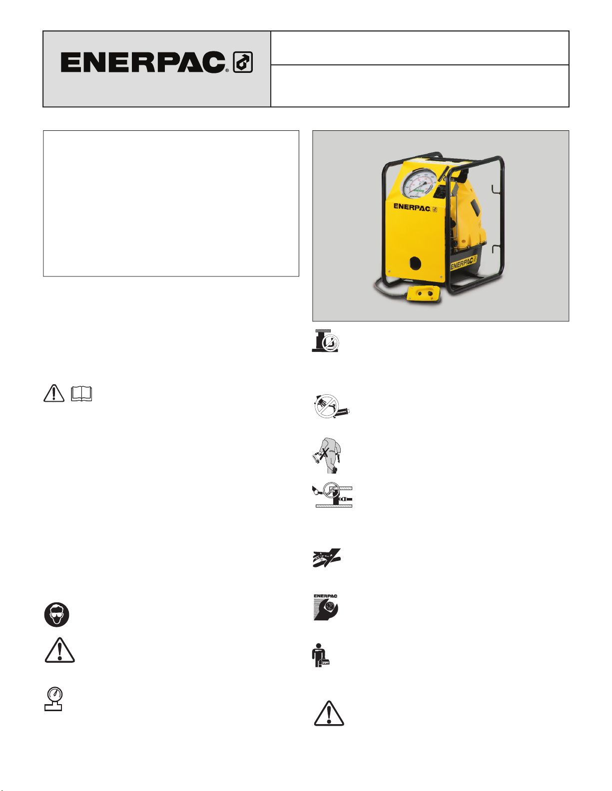
Model ZUTP-1500
1500 Bar Electric Pump
CAUTION: Avoid damaging hydraulic hose. Avoid
sharp bends and kinks when routing hydraulic hoses.
Using a bent or kinked hose will cause severe back-pressure.
Sharp bends and kinks will internally damage the hose leading to
premature hose failure.
Do not drop heavy objects on hose. A sharp impact
may cause internal damage to hose wire strands.
Applying pressure to a damaged hose may cause it
to rupture.
IMPORTANT: Do not lift hydraulic equipment by the
hoses or swivel couplers. Use the carrying handle or
other means of safe transport.
CAUTION: Keep hydraulic equipment away from
fl ames and heat. Excessive heat will soften packings
and seals, resulting in fl uid leaks. Heat also weakens
hose materials and packings. For optimum performance do not
expose equipment to temperatures of 65°C [150°F] or higher.
Protect hoses and cylinders from weld spatter.
DANGER: Do not handle pressurized hoses. Escaping
oil under pressure can penetrate the skin, causing
serious injury. If oil is injected under the skin, see a
doctor immediately.
IMPORTANT: Hydraulic equipment must only be
serviced by a qualifi ed hydraulic technician. For repair
service, contact the Authorized ENERPAC Service Center
in your area. To protect your warranty, use only ENERPAC oil.
WARNING: Immediately replace worn or damaged parts
with genuine ENERPAC parts. Standard grade parts will
break causing personal injury and property damage.
ENERPAC parts are designed to fi t properly and withstand high
loads.
WARNING: Do not use electric pumps in an explosive
atmosphere. Adhere to all local and national electrical
codes. A qualifi ed electrician must do installation and
modifi cation.
1
WARNING: Keep hands clear of moving parts and
pressurized hoses.
WARNING: These pumps have internal factory
adjusted relief valves, which must not be repaired or
adjusted except by an Authorized Enerpac Service
Center.
WARNING: To prevent damage to pump electric motor,
check specifi cations. Use of incorrect power source
will damage the motor.
2.2 Safety Precautions - Model ZUTP-1500 Pump
DANGER:
may result in serious personal injury or death!
• Always wear eye protection, gloves and boots when operating
the pump.
• High pressure hydraulic equipment can be very dangerous if
misused. Keep away from oil leakages at high pressure. Liquid
escaping from highly pressurized equipment has suffi cient
power to penetrate the skin, which can cause blood poisoning.
In the case of such an accident, seek IMMEDIATE medical
attention.
• Never attempt to disconnect a hydraulic
coupler while it is under pressure.
• Never attempt to repair leaks while the
system is pressurized. Be sure system
pressure gauge indicates zero (0) psi/
bar before making any repairs.
• Never pressurize the back of a
disconnected male coupler.
Serious personal injury could
result if the coupler fails while
under pressure.
• Use caution when pressurizing a
system. Pressure can rise faster
than anticipated. Continuously
monitor the pressure gauge during pressurization. Be prepared
to stop pressurization immediately at any time.
• Before operation, ensure that quick-disconnect couplings are
properly connected by physically pulling on them.
Failure to observe the following precautions
0
0
• Allow only trained and experienced personnel to operate the
pump. Be especially careful to avoid accidental pump start-up.
• Never leave the pump pressurized and unattended. Always
depressurize before leaving the system unattended.
• Never exceed the safe working pressure for the hydraulic
hoses, tools or pump.
• The Model ZUTP-1500 pump is designed to operate at a
maximum working pressure of 21,750 psi [1500 bar]. Do not
exceed this pressure setting.
WARNING:
Do not operate the pump at pressure settings
above 21,750 psi [1500 bar]. Hydraulic components
could rupture or burst. Serious personal injury and
property damage may result!
3.0 SPECIFICATIONS
(See technical data charts at bottom of page)
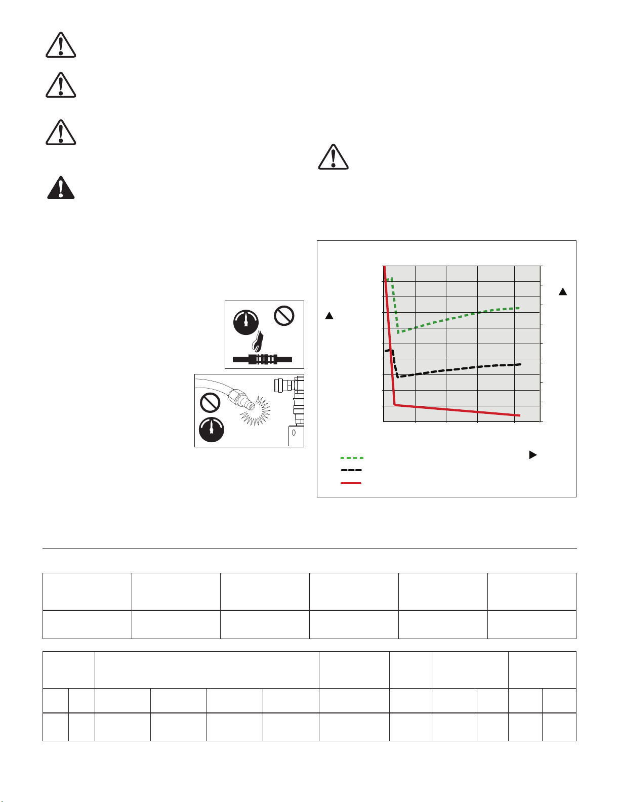
3.1 Flow, Pressure and Current Draw (typical)
in /min3L/min
200 [3,27]
180 [2,94]
160 [2,62]
140 [2,29]
120 [1,96]
100 [1,63]
Flow
80 [1,31]
60 [0,98]
40 [0,65]
20 [0,32]
115 V
230 V
0
0 5,000
[350]
Amps (115 V)
Amps (230 V)
10,000
[700]
15,000
[1000]
21,750
[1500]
Pressure psi
[bar]
16
14
12
10
8
6
4
2
0
Current Draw (amps)
Flow
Note: Actual fl ow, pressure and current draw will vary, depending
on power supply, application, pump condition and other factors.
Technical Data – Model ZUTP-1500
Temperature
Range
-20ºF to +140ºF
[-29ºC to +50ºC]
Motor
Size
hp kW
1.7 1.25
0 psi
[0 bar]
180 in3/min
[2,94 L/min]
Oil Viscosity
Range
150 -165 S.U.S.
[15 - 25 C.S.T.]
Output Flow Rate Motor
10,000 psi
[700 bar]
15 in3/min
[0,24 L/min]
Hydraulic
Oil Type
(recommended)
Enerpac HF
15,000 psi
[1000 bar]
12 in3/min
[0,19 L/min]
21,750 psi
[1500 bar]
8 in3/min
[0,13 L/min]
Seal Materials Max. Hydraulic
Buna, Viton
& Polyurethane
Electrical
Working Pressure
21,750 psi
[1500 bar]
Sound
Level
Reservoir
Oil Capacity
Current Draw
Specifi cations
Volts-Ph-Hz dBA gallons liters lbs kg
115-1-50/60
230-1-50/60
2
89 1 3,8 65 29,4
Electric
(Refer to graph
in Section 3.1)
Weight
With Oil
4.0 INSTALLATION
Install or position the pump to ensure that air fl ow around the
motor and pump is unobstructed. Keep the motor clean to
ensure maximum cooling during operation.
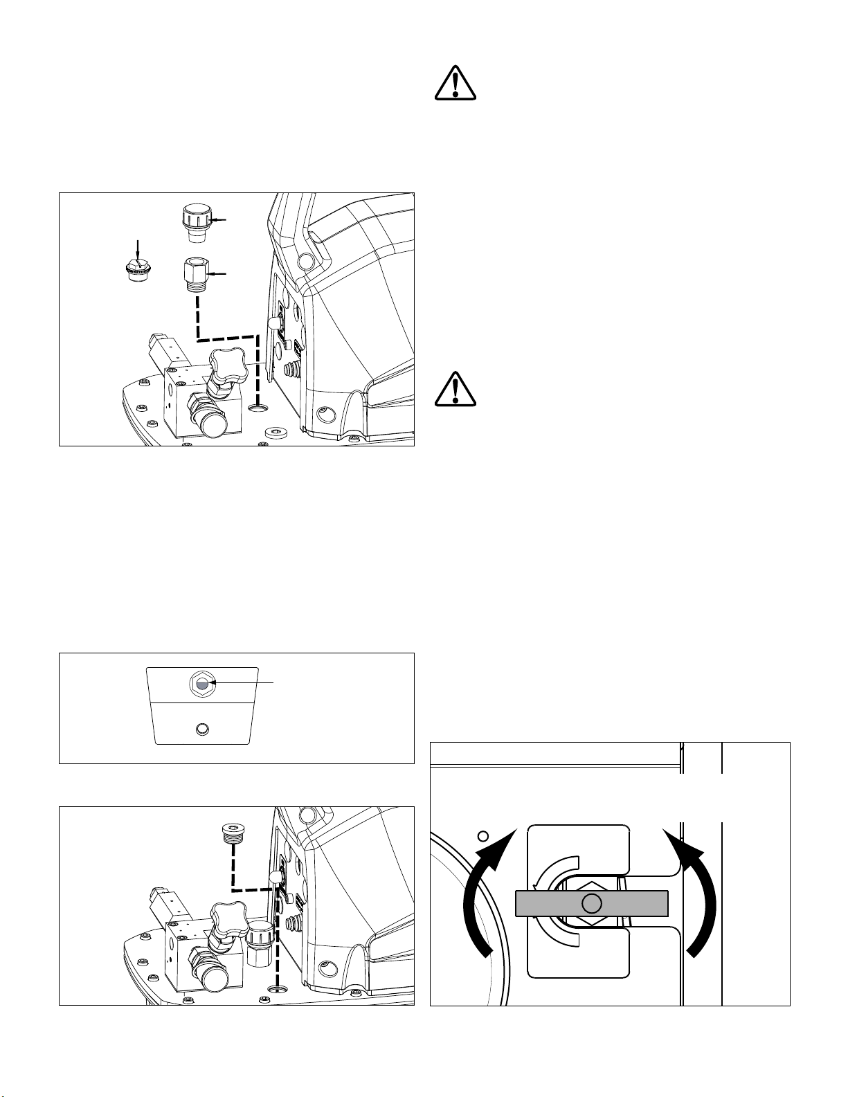
4.1 Air Breather (See Figure 1)
A shipping plug (A) is installed in the breather port on the top of
the reservoir. Before using the pump, replace the shipping plug
(A) with the air breather (B) and adapter fi tting (C).
B
A
C
Figure 1, Air Breather
4.2 Oil Level (See Figures 2 and 3)
Check the pump oil level prior to start-up. The reservoir is full
when the oil level is as shown in Figure 2. If necessary, remove
the oil fi ll plug from the cover plate as shown in Figure 3 and add
oil as required.
IMPORTANT: Add oil only when all system components are fully
retracted, or the system will contain more oil than the reservoir
can hold. Reservoir capacity is approximately 1 gallon [3,8 liters].
4.3 Electrical Connections
WARNING: The pump is factory equipped with the
common electrical plug for a given voltage. Altering the
plug type should only be done by a qualifi ed electrician,
adhering to all applicable local and national codes.
• The disconnect and line circuit protection is to be provided by
customer. Line circuit protection is to be 115 percent of motor full
load current at maximum pressure of application.
• For additional information, refer to power rating on pump name
plate. Also refer to graph in Section 3.1.
4.4 Hydraulic Connections
• A female quick-disconnect fi tting (Enerpac Model BR150) is
installed at the pump oil outlet. This fi tting is rated at 21,750 psi
[1500 bar].
• Enerpac recommends the use of Enerpac HT 1500 Series
thermoplastic hoses with the Model ZUTP-1500 pump. These
hoses are rated at 21,750 psi [1500 bar]. Refer to Enerpac
instruction sheet L2733 for use, safety and maintenance
information.
WARNING: The Model ZUTP-1500 pump must be
operated only with hoses and fi ttings rated to operate
at 21,750 psi [1500 bar] working pressure. Hydraulic
hoses and fi ttings of a lower pressure rating will rupture or burst.
Serious personal injury could result!
• Before connecting hose to pump oil outlet, check that pump
pressure gauge indicates zero (0) psi/bar. If any pressure is
indicated, fully open the pressure release valve to relieve
pressure. See Section 5.1.
5.0 OPERATION
5.1 Pressure Release Valve (See Figure 4)
Valve Positions:
1. CLOSED - Flow directed to pump hydraulic outlet port.
Pressure builds when pump motor is turned on. Pump holds
pressure when motor is turned off.
2. OPEN - Pressure released to pump hydraulic reservoir.
Pressure will not build when motor is turned on.
Tank is full
when oil level
is here.
Figure 2, Oil Level Sight Glass
Figure 3, Oil Fill Plug
IMPORTANT: Close the pressure release valve using hand force
only. Overtightening and/or use of tools may result in damage to
the valve and/or valve seat.
CLOSED
(oil fl ow to tool)
OPEN
(pressure release
to reservoir)
PRESSURE RELEASE VALVE
OPEN SLOWLY
OPEN
CLOSE
DO NOT CLOSE
USING EXCESSIVE FORCE
Figure 4, Pressure Release Valve
3

5.2 Pendant and Motor Jog Buttons
(See Figures 5 and 6)
The pump motor can be controlled either by the pendant button
or by the motor jog button (located on the pump front panel).
Relief Valve
Knob
Pendant Button
MOTOR
JOG
Figure 6, Motor Jog Button
Operation is the same for both
buttons:
Button pressed:
Motor starts. System pressure
builds and tool is actuated for as
long as button is held down.
Button released:
Motor stops. Check valve holds
Figure 5, Pendant
Note: Pressure release valve (see Figure 4) must be fully closed
to allow pressure to build while motor is running.
5.3 Adjusting the Relief Valve Setting (See Figure 7)
1. Remove hose (if connected) from the quick disconnect
coupler at the oil outlet port.
2. Fully close the pressure release valve. See Figure 4.
3. Loosen the relief valve locknut to allow pressure adjustment.
See Figure 7.
4. Turn the relief valve knob several turns counter-clockwise, so
that the relief valve is set lower than the desired setting.
Notes:
• When adjusting relief valve setting, always start at a low
pressure and slowly increase the pressure to the desired setting.
• If desired, the motor jog button can be used in place of the
pendant button during the following steps.
5. Check that pump is connected to electrical power.
6. Press and hold the pendant button. See Figure 5. The pump
motor will start and pressure will begin building immediately.
7. While continuing to press and hold the pendant button,
slowly turn the relief valve knob clockwise (as required) until
the desired pressure reading is shown on the pump pressure
gauge.
WARNING: Pump maximum working pressure is
21,750 psi [1500 bar]. Do not set the relief valve
pressure above 21,750 psi [1500 bar].
8. Release the pendant button. The pump motor will stop.
pressure until pressure release
valve is opened.
Locknut
Figure 7, Relief Valve
Notes:
• Rotating the relief valve knob counter-clockwise will NOT
reduce or relieve existing system pressure.
• If pressure is adjusted too high, relieve pressure by opening the
pressure release valve (see Figure 4) until the pump pressure
gauge indicates zero (0) psi/bar. Then, fully close the pressure
release valve and repeat steps 6 through 8.
9. After verifying that setting is correct, tighten the relief valve
locknut (hand tight only - do not overtighten) to lock the
setting. See Figure 7.
10. Slowly open the pressure release valve to relieve pressure
in the oil outlet line. See Figure 4. Verify that pump pressure
gauge indicates zero (0) psi/bar.
5.4 Pressurizing the System
1. Adjust the relief valve setting. Refer to Section 5.3.
2. Connect hydraulic hose(s) and tool(s). Refer to Section 4.4.
3. Close the pressure release valve. See Figure 4.
4. Check that pump is connected to electrical power.
CAUTION: Before pressurizing the system, read and
understand all instructions and safety precautions
applicable to the hydraulic tool(s) being used. Follow
safe work practices in accordance with all applicable laws,
regulations and industry standards.
CAUTION: Continuously monitor the pump pressure
gauge while pump is running. Pressures can rise faster
than anticipated.
5. Press and hold the pendant button. See Figure 5. The pump
motor will start and pressure will begin building immediately.
6. When the desired reading is shown on the pump pressure
gauge, release the pendant button. The pump motor will
stop.
Note: Time required to pressurize the hydraulic circuit will vary,
depending on the number and type of tools connected, hydraulic
hose lengths and other factors.
4

5.5 Depressurizing the System
1. Slowly open the pressure release valve to relieve system
pressure. See Figure 4.
2. Verify that the pump pressure gauge indicates zero (0) psi/bar.
5.6 Circuit Breaker
The pump circuit breaker is
located on the pump front
panel, beside the pump jog
button.
In the event of an electrical
overload, the pump circuit
breaker will trip. After
investigating and correcting
the source of the overload,
push the circuit breaker
button to reset.
WARNING: To avoid injury and equipment damage, do
not continue pressurizing hydraulic tools after they
reach maximum travel or maximum operating pressure.
(See Figure 8)
CIRCUIT BREAKER
Press to Reset
Figure 8, Circuit Breaker
6.0 MAINTENANCE
Frequently inspect all system components for leaks or damage.
Repair or replace damaged components. Electrical components,
such as the power cord, may only be repaired or replaced by a
qualifi ed electrician, adhering to all applicable local and national
codes.
WARNING: Disconnect pump from electrical power
before performing any maintenance or repairs. Be sure
all hydraulic pressure is completely relieved (0 psi/bar).
6.1 Check Oil Level
Check the pump oil level prior to start-up. If oil level is low,
remove the oil fi ll plug from the cover plate and add oil as needed.
See fi gures 2 and 3. Always be sure that hydraulic tools are fully
retracted before adding oil to the reservoir.
6.2 Change Oil and Clean Reservoir
Enerpac HF oil is a crisp blue color. Frequently check oil condition
for contamination by comparing pump oil to new Enerpac oil. As
a general rule, completely drain and clean the reservoir every 250
hours, or more frequently if used in dirty environments.
Note: The following procedure requires that you remove the
pump from the reservoir. Work on a clean bench and dispose of
used oil in accordance with all applicable laws and regulations.
1. Disconnect pump from electrical power.
2. Remove the drain plug and drain all oil from the reservoir.
Clean and reinstall the drain plug.
3. Unscrew the 13 bolts holding the cover plate to the reservoir
and lift the pump unit out of the reservoir. Be careful not to
damage the oil intake fi lter screen.
4. Thoroughly clean the reservoir with a suitable cleaning agent.
5. Remove the oil intake fi lter screen for cleaning. (Do not pull
on the screen or the bottom of the intake to avoid possible
damage.) Clean the screen with solvent and a soft brush.
Reinstall.
6. Reassemble the pump and reservoir, installing a new reservoir
gasket.
7. Disassemble the hydraulic return line fi lter. Clean and
reinstall (or replace) the fi lter element. Refer to Section 6.3 for
additional information.
8. Fill the reservoir with clean Enerpac HF hydraulic oil. The
reservoir is full when oil level is as shown in Figure 2.
6.3 Hydraulic Return Line Filter (See Figure 9)
Remove and inspect the hydraulic return line fi lter element at
every oil change. The element can be cleaned and reused if it is
in good condition. However, a new element should be installed if
the old element is damaged or has been cleaned more than three
times.
2
1
OIL OUT OIL IN
Key:
1. End Cap
2. O-Ring
3. Spring
4. Housing
5. Spring
6. Element, 90 Micron (Arrow P/N EK9052V-90)
7. Gasket
7
Note: For additional information,
go to www.arrowpneumatics.com.
Figure 9, Hydraulic Return Line Filter
3
4
5 6
6.4 Motor Brush Replacement (See Figure 10)
To prevent motor damage, the pump motor brushes incorporate
an automatic motor stop when one of the brush carbons wears
to a length of 0.25" [6 mm]. Inspect both brushes.
1. Disconnect pump from electrical power.
DANGER: To avoid possible electrocution, pump must
be completely disconnected from electrical power
before brush servicing is attempted.
2. Remove both brush caps (A) by defl ecting the brush cap latch
(B) and gently prying outward. See Figure 10.
3. Remove motor brushes by turning black cap counter-
clockwise.
4. Replace both brushes and reverse procedure to reassemble.
A
B
Figure 10, Brush Cap Removal
A. Brush Cap B. Brush Cap Latch
5

7.0 TROUBLESHOOTING
Only qualifi ed hydraulic technicians should service the pump or system components. A system failure is not necessarily the result of
a pump malfunction. To determine the cause of the problem, the complete system must be considered in any diagnostic procedure.
The following troubleshooting chart is intended to be used only as an aid in determining if a problem exists. For repair service, contact
your Enerpac Authorized Service Center.
Troubleshooting Guide
Problem Possible Cause Action
Pump will not start. No power. Connect power.
Pump circuit breaker tripped. Push pump circuit breaker button to reset.
Low voltage. Turn off other electric loads.
Use heavier gauge extension cord.
Motor brushes worn to end of life. Replace brushes per Section 6.4.
Pump element jammed. See authorized service center.
Pendant damage. Repair pendant.
See authorized service center.
Motor stops under load. Low voltage. Turn off other electric loads.
Use heavier gauge extension cord.
Pump fails to build pressure or
builds less than full pressure.
Low oil level in reservoir. Add oil per Section 4.2.
Relief valve setting too low. Adjust per Section 5.3.
External system leak. Inspect and repair or replace.
Pump pressure release valve open or not fully
closed.
Pump hydraulic intake screen dirty. Clean or replace hydraulic intake screen.
Close pressure release valve.
Change hydraulic oil. See Section 6.2.
Internal leak in pump pressure release valve. See authorized service center.
Internal leak in system component. See authorized service center.
Pump builds full pressure, but tool
does not move.
Low oil fl ow. Pump hydraulic intake screen dirty. Clean or replace hydraulic intake screen.
Tool drifts back on its own. External system leak. Inspect all hydraulic connections and replace or repair.
Tool will not return when
pressure is relieved.
Load greater than tool capacity at full pressure. Reduce load or add tool capacity.
Flow to tool blocked. Check hydraulic couplers for full engagement.
Check hose for blockage or kinks.
Change hydraulic oil. See Section 6.2.
Pump check valve malfunctioning. See authorized service center.
Internal leak in a system component. See authorized service center.
Tool is not spring return. Manually retract tool as required.
Flow restricted or blocked. Check hydraulic couplers for full engagement.
Check hose for blockage or kinks.
Pump hydraulic return fi lter dirty. Clean or replace hydraulic return fi lter element.
Pressure release valve malfunction. See authorized service center.
Return spring broken.
(tools equipped with return spring only)
Pump runs hot. Flow restricted. Check hydraulic couplers for full engagement.
6
See authorized service center.
Check hose for blockage or kinks.

NOTES:
7

A
A
A
A
A
Enerpac Worldwide Locations e-mail: info@enerpac.com internet: www.enerpac.com
ustralia and New Zealand
ctuant Australia Ltd.
Block V Unit 3
Regents Park Estate
391 Park Road
Regents Park NSW 2143
(P.O. Box 261) Australia
T +61 297 438 988
F +61 297 438 648
sales-au@enerpac.com
Brazil
Power Packer do Brasil Ltda.
Rua dos Inocentes, 587
04764-050 - Sao Paulo (SP)
T +55 11 5687 2211
F +55 11 5686 5583
Toll Free: 0800 891 5770
vendasbrasil@enerpac.com
Canada
ctuant Canada Corporation
6615 Ordan Drive, Unit 14-15
Mississauga, Ontario L5T 1X2
T +1 905 564 5749
F +1 905 564 0305
Toll Free:
T +1 800 268 4987
F +1 800 461 2456
customer.service@actuant.com
China (Taicang)
ctuant (China) Industries Co. Ltd.
No. 6 Nanjing Road,
Taicang Economic Dep Zone
Jiangsu, China
T +86 0512 5328 7500
F +86 0512 5335 9690
sales-cn@enerpac.com
China (Beijing)
ctuant (China) Industries Co. Ltd.
709B Diyang Building
Xin No. 2, Dong San Huan North Rd.
Beijing City, 100028 China
T +86 10 845 36166
F +86 10 845 36220
sales-cn@enerpac.com
France, Switzerland, North Africa
and French speaking African
countries
ENERPAC
Une division d’ACTUANT France
S.A.S.
ZA de Courtaboeuf
32, avenue de la Baltique
91140 VILLEBON /YVETTE
France
T +33 1 60 13 68 68
F +33 1 69 20 37 50
sales-fr@enerpac.com
Germany and Austria
ENERPAC GmbH
P.O. Box 300113
D-40401 Düsseldorf
Willstätterstrasse 13
D-40549 Düsseldorf, Germany
T +49 211 471 490
F +49 211 471 49 28
sales-de@enerpac.com
India
ENERPAC Hydraulics Pvt. Ltd.
No. 1A, Peenya Industrial Area
IInd Phase, Bangalore, 560 058, India
T +91 80 40 792 777
F +91 80 40 792 792
sales-in@enerpac.com
Italy
ENERPAC S.p.A.
Via Canova 4
20094 Corsico (Milano)
T +39 02 4861 111
F +39 02 4860 1288
sales-it@enerpac.com
Japan
Applied Power Japan LTD KK
Besshocho 85-7
Kita-ku, Saitama-shi 331-0821, Japan
T +81 48 662 4911
F +81 48 662 4955
sales-jp@enerpac.com
Middle East, Egypt and Libya
ENERPAC Middle East FZE
Office 423, LOB 15
P.O. Box 18004, Jebel Ali, Dubai
United Arab Emirates
T +971 (0)4 8872686
F +971 (0)4 8872687
sales-ua@enerpac.com
Russia
Rep. office Enerpac
Russian Federation
Admirala Makarova Street 8
125212 Moscow, Russia
T +7 495 98090 91
F +7 495 98090 92
sales-ru@enerpac.com
Singapore
Actuant Asia Pte Ltd.
83 Joo Koon Circle
Singapore 629109
T +65 68 63 0611
F +65 64 84 5669
Toll Free: +1800 363 7722
sales-sg@enerpac.com
South Korea
Actuant Korea Ltd.
3Ba 717, Shihwa Industrial Complex
Jungwang-Dong, Shihung-Shi,
Kyunggi-Do
Republic of Korea 429-450
T +82 31 434 4506
F +82 31 434 4507
sales-kr@enerpac.com
Spain and Portugal
ENERPAC SPAIN, S.L.
Avda. Los Frailes, 40 – Nave C & D
Pol. Ind. Los Frailes
28814 Daganzo de Arriba
(Madrid) Spain
T +34 91 884 86 06
F +34 91 884 86 11
sales-es@enerpac.com
Sweden, Denmark, Norway, Finland
and Iceland
Enerpac Scandinavia AB
Fabriksgatan 7
412 50 Gothenburg
Sweden
T +46 (0) 31 799 0281
F +46 (0) 31 799 0010
scandinavianinquiries@enerpac.com
The Netherlands, Belgium,
Luxembourg,
Central and Eastern Europe,
Baltic States, Greece, Turkey
and CIS countries
ENERPAC B.V.
Galvanistraat 115
6716 AE Ede
P.O. Box 8097
6710 AB Ede
The Netherlands
T +31 318 535 800
F +31 318 535 848
sales-nl@enerpac.com
Enerpac Integrated Solutions B.V.
Opaalstraat 44
7554 TS Hengelo
P.O. Box 421
7550 AK Hengelo
The Netherlands
T +31 74 242 20 45
F +31 74 243 03 38
integratedsolutions@enerpac.com
South Africa and other English
speaking African countries
ENERPAC B.V.
Galvanistraat 115
6716 AE Ede
P.O. Box 8097
6710 AB Ede
The Netherlands
T +31 318 535 911
F +31 318 525 613
sales-za@enerpac.com
United Kingdom and Ireland
ENERPAC Ltd.,
Bentley Road South
Darlaston, West Midlands
WS10 8LQ
England
T +44 (0)121 50 50 787
F +44 (0)121 50 50 799
sales-uk@enerpac.com
USA, Latin America and Caribbean
ENERPAC
P.O. Box 3241
6100 N. Baker Road
Milwaukee
WI 53209 USA
T +1 262 781 6600
F +1 262 783 9562
User inquiries:
+1 800 433 2766
Distributor inquiries/orders:
+1 800 558 0530
sales-us@enerpac.com
All Enerpac products are guaranteed
against defects in workmanship and
materials for as long as you own them.
For the location of your nearest authorized
Enerpac Service Center, visit us at
www.enerpac.com
01/25/11
 Loading...