

Instruction Sheet
POWERFUL SOLUTIONS. GLOBAL FORCE.
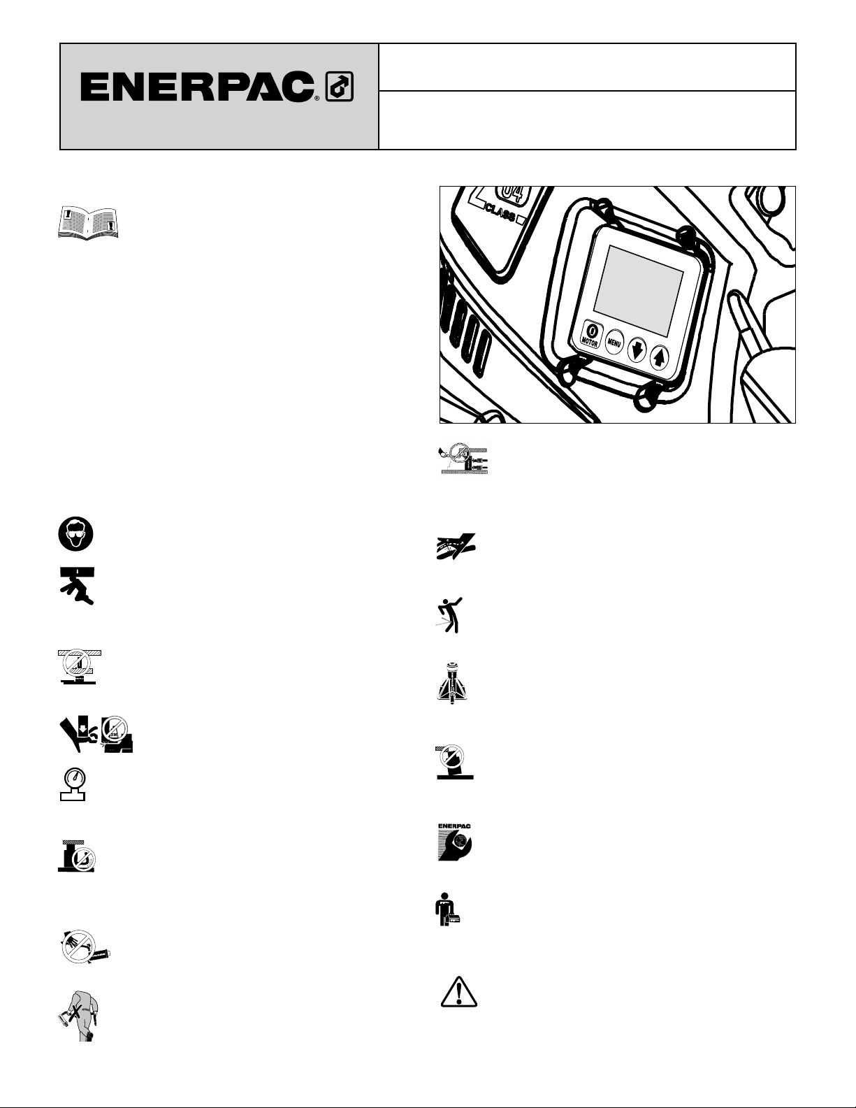
LCD Control Panel Operation - Firmware 7.x
L2940 Rev. A 07/09
1.0 SAFETY ISSUES
Read all instructions, warnings and cautions
carefully. Follow all safety precautions to avoid
personal injury or property damage during system
operation. Enerpac cannot be responsible for damage or injury
resulting from unsafe product use, lack of maintenance or
incorrect product and/or system operation. Contact Enerpac
when in doubt as to the safety precautions and operations. If you
have never been trained on high-pressure hydraulic safety,
consult your distribution or service center for a free Enerpac
Hydraulic safety course.
Failure to comply with the following cautions and warnings could
cause equipment damage and personal injury.
A CAUTION is used to indicate correct operating or maintenance
procedures and practices to prevent damage to, or destruction
of equipment or other property.
A WARNING indicates a potential danger that requires correct
procedures or practices to avoid personal injury.
A DANGER is only used when your action or lack of action may
cause serious injury or even death.
WARNING: Wear proper personal protective gear when
operating hydraulic equipment.
WARNING: Stay clear of loads supported by
hydraulics. A cylinder, when used as a load lifting device,
should never be used as a load holding device. After the
load has been raised or lowered, it must always be blocked
mechanically.
WARNING: USE ONLY RIGID PIECES TO HOLD
LOADS. Carefully select steel or wood blocks that are
capable of supporting the load. Never use a hydraulic
cylinder as a shim or spacer in any lifting or pressing application.
DANGER: To avoid personal injury keep hands
and feet away from cylinder and workpiece
during operation.
WARNING: The system operating pressure must not
exceed the pressure rating of the lowest rated component
in the system. Install pressure gauges in the system to
monitor operating pressure. It is your window to what is happening
in the system.
CAUTION: Avoid damaging hydraulic hose. Avoid
sharp bends and kinks when routing hydraulic hoses.
Using a bent or kinked hose will cause severe back-pressure.
Sharp bends and kinks will internally damage the hose leading to
premature hose failure.
Do not drop heavy objects on hose. A sharp impact
may cause internal damage to hose wire strands.
Applying pressure to a damaged hose may cause it
to rupture.
IMPORTANT: Do not lift hydraulic equipment by the
hoses or swivel couplers. Use the carrying handle or
other means of safe transport.
Z-Class Electric Pumps
CAUTION: Keep hydraulic equipment away from
fl ames and heat. Excessive heat will soften packings
and seals, resulting in fl uid leaks. Heat also weakens
hose materials and packings. For optimum performance do not
expose equipment to temperatures of 65°C [150°F] or higher.
Protect hoses and cylinders from weld spatter.
DANGER: Do not handle pressurized hoses. Escaping
oil under pressure can penetrate the skin, causing
serious injury. If oil is injected under the skin, see a
doctor immediately.
WARNING: Only use hydraulic cylinders in a coupled
system. Never use a cylinder with unconnected couplers. If
the cylinder becomes extremely overloaded, components
can fail catastrophically causing severe personal injury.
WARNING: BE SURE SETUP IS STABLE BEFORE
LIFTING LOAD. Cylinders should be placed on a fl at
surface that can support the load. Where applicable, use
a cylinder base for added stability. Do not weld or otherwise
modify the cylinder to attach a base or other support.
Avoid situations where loads are not directly centered
on the cylinder plunger. Off-center loads produce
considerable strain on cylinders and plungers. In
addition, the load may slip or fall, causing potentially dangerous
results.
IMPORTANT: Hydraulic equipment must only be serviced
by a qualifi ed hydraulic technician. For repair service,
contact the Authorized ENERPAC Service Center in your
area. To protect your warranty, use only ENERPAC oil.
WARNING: Immediately replace worn or damaged parts
with genuine ENERPAC parts. Standard grade parts will
break causing personal injury and property damage.
ENERPAC parts are designed to fi t properly and withstand high
loads.
WARNING: Do not use electric pumps in an explosive
atmosphere. Adhere to all local and national electrical
codes. A qualifi ed electrician must do installation and
modifi cation.
WARNING: Keep hands clear of moving parts and
pressurized hoses.
One
Button
Three
Button
WARNING: These pumps have internal factory adjusted
relief valves, which must not be repaired or adjusted
except by an Authorized Enerpac Service Center.
WARNING: To prevent damage to pump electric motor,
check specifi cations. Use of incorrect power source
will damage the motor.
2.0 STARTUP
IMPORTANT:
• Pumps with optional pressure transducer: Review Automode
information in sections 4.0 and 5.0 before starting pump.
• Pumps with optional pressure switch: Review section 6.7 G
before starting pump.
1. Check the oil level of pump and add oil if necessary. Refer to
pump instruction sheet.
2. Make sure the shipping plug has been removed and the
breather cap is installed. Refer to pump instruction sheet.
3. Place manual control valve (all models NOT equipped with
electric valve) in the Neutral position.
4. Connect unit to power. Wait about 2 seconds - until “READY” is
displayed - before pressing any button on shroud or pendant.
Refer to section 6.2 for additional boot sequence information
Note: During the boot sequence, the microprocessor will identify
operation of any button as a potential malfunction and will
prevent the motor from starting. Reset by disconnecting power
for 10 seconds.
5. Adjust relief valve as described in section 5.0.
6. For Motor On/Off and valve operation: refer to sections 3.1
through 3.4 for instructions applicable to your specifi c valve
and pendant confi guration. For models equipped with a foot
switch, refer to section 3.5.
3.0 VALVE, PENDANT AND FOOT SWITCH
OPERATION
2
2
3.1 Manual Valve
Operation
VM32 (See Fig. 1)
1. Advance
2. Retract
Shroud On/Off=
Toggle Motor On or Off
Tank
Tank
Pressure
Pressure
Figure 1
Figure 1
1
1
® ®
Up Arrow/
ON/OFF
Up Arrow
Down Arrow
ON / OFF
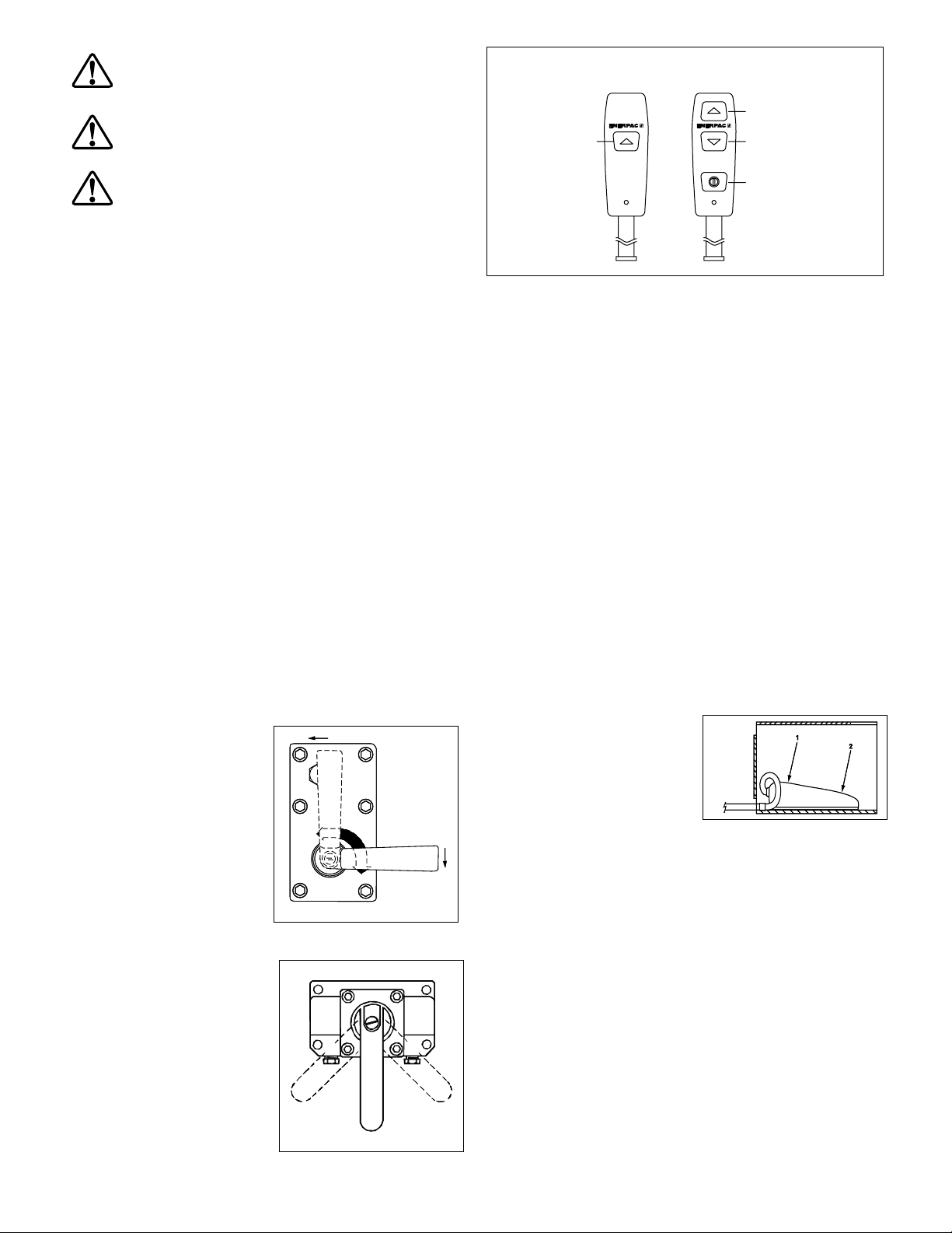
Figure 3, Pendant Button Variations
3.3 VE33, VE43 and VEW43P Electric Valves with
3-Button Pendant Operation
Also known as a Remote Pump - oil fl ow and motor are both
controlled by the pendant (see Fig. 3).
1. Up Arrow = Momentary Advance
2. Down Arrow = Momentary Retract
3. On/Off = Toggle Motor On or Off
Shroud On/Off = Toggle motor On or Off
3.4 VE32D Electric Valve with 1-Button Pendant
Operation
Also known as a Dump Pump - Oil fl ow and motor are both
controlled by the pendant. The pump will run and the cylinder
will advance when the pendant button is pressed. Releasing the
button will stop the pump and the cylinder will retract automatically
(see Fig. 3).
1. Up Arrow = Momentary Advance
Shroud On/Off = Toggle Motor Off Only
3.5 Valves with foot switch (See Fig. 4)
A. All valves except VE32D
1. Momentary advance or motor
on
2. Momentary retract (if
applicable)
Shroud On/Off = Toggle Motor
On or Off
Figure 4Figure 4
B. VE32D valves
1. Not used
2. Momentary advance
Shroud On/Off = Toggle Motor Off
3.2 VM33, VM33L, VM43,
and VM43L
(See Fig. 2)
1. Advance
2. Retract
3. Neutral
Shroud On/Off =
Toggle Motor On or Off
3 - In Use
3 - In Use
A
B
B
2
2
Figure 2
Figure 2
A
1
1
3
3
2

4.0 AUTOMATIC PUMP OPERATION
(Pumps equipped with pressure transducer option)
Pumps equipped with the pressure transducer option have the
ability to react automatically at a user-defi ned upper and lower
pressure value. This feature is called “Automode”.
Automode can be turned on or off as desired, at the LCD control
panel.
Automode controlled operation of the motor and electric valve
(if equipped) will vary, depending on pump type . The pump type
appears briefl y on the LCD when power is connected to the
pump.
Refer to Table 1 for a list of the pump types covered in this
manual. Refer to Table 4, Pump Model Matrix, (located near the
end of this document) for a description of the specifi c operational
characteristics for each pump type.
Table 1 - Pump Types
Number Pump/Valve Description
1 . . . . . . . . . . . . . . . . . . . Manual w/LCD (manual valve)
2 . . . . . . . . . . . . . . . . . . . Advance/Hold /Retract (electric valve)
3 . . . . . . . . . . . . . . . . . . . Dump (electric valve)
6 . . . . . . . . . . . . . . . . . . . Remote 3 or 4-Way (electric valve)
8 . . . . . . . . . . . . . . . . . . . Jog (manual valve)
10 . . . . . . . . . . . . . . . . . . 3 or 4-Way Manual Momentary
. . . . . . . . . . . . . . . . . . . Local Mode Default (electric valve)
4.1 Overview of Automode Operation
Refer to paragraphs A through D of this section for an overview
of Automode operation and features.
4.1 A. If Automode is ON, and LO PRESS setting is
greater than zero (Pump types 1, 2, 6, 8 and 10)
I. Before the HI PRESS value is reached:
• The pendant buttons and shroud On/Off button will function as
described in sections 3.1 – 3.4.
• The text “AUTO” will be shown on the LCD, reminding the
operator that Automode is active, and that the pump will take
control when system pressure rises to the HI PRESS value.
II. After the HI PRESS value is reached:
• Pump types 1 and 8: The pump motor will stop.
• Pump type 2: The pump motor will stop and the electric valve
will shift.
• Pump types 6 and 10: The pump motor will keep running and
the electric valve will shift.
• The LCD text will change from “AUTO” to “AUTO ON” and the
LCD backlight will begin fl ashing on and off. This indicates that
Automode is now controlling pump operation automatically as
required to maintain the set pressure range.
WARNING: All personnel must be aware that motor can
start and/or valve can shift at any time when backlight
is fl ashing and “AUTO ON” is displayed on the LCD.
WARNING: Always set Automode to OFF and
disconnect electrical power to pump before
disconnecting hoses or performing any
adjustments, maintenance or repairs.
III. When system pressure drops to the LO PRESS value:
• Pump types 1 and 8: The pump motor will restart.
• Pump types 6 and 10: The electric valve will shift.
• Pump type 2: The pump motor will restart and the electric
valve will shift.
4.1 B. If Automode is ON, and LO PRESS setting is set
to zero (0) or OFF (Pump types 1, 2, 3, 6, 8 and 10)
Note: On pump type 3 only, the LO PRESS function is not used,
and is automatically set to zero (0) by the microcontroller.
I. Before the HI PRESS value is reached:
• The pendant buttons and shroud On/Off button will function
as described in sections 3.1 – 3.4.
• The text “AUTO” will be shown on the LCD, reminding the
operator that Automode is active, and that the pump will take
control when system pressure rises to the HI PRESS value.
II. After the HI PRESS value is reached:
• Pump types 1, 2, 3 and 8: The pump motor will stop and the
electric valve will shift.
• Pump types 6 and 10: The pump motor will keep running and
the electric valve will shift.
• The LCD will continue to display “AUTO” and the LCD backlight
will remain turned on (will not fl ash on and off).
4.1 C. If Automode is OFF
(Pump types 1, 2, 3, 6, 8 and 10)
• The LCD will display “READY” in the text area.
• The LCD will indicate system pressure as a simple pressure
gauge, no additional actions will be performed regardless of
previously set HI PRESS and LO PRESS values.
4.1 D. Additional Information
• Pressing and releasing any button on the pendant (if equipped)
or shroud will stop the automatic cycle. Pressing the pendant
Down-Arrow (if applicable) will also retract the cylinder. Pressing
the motor On/Off button will also de-energize the motor if it is
running.
• To restart the automatic cycle, press and release the pendant
Up-Arrow button (if applicable) or the motor On/Off button (See
section 3.1– 3.4).
• Refer to sections 6.1 through 6.5 later in this document for
and detailed LCD operating instructions and descriptions of the
Automode LCD screens.
3
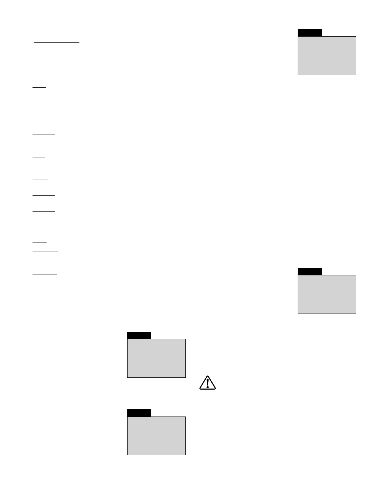
5.0 RELIEF VALVE ADJUSTMENT
Z-Class pumps are equipped with one user adjustable relief valve
(see Figure 5.)
IMPORTANT: To ensure proper pump operation:
• On pumps equipped with the optional pressure transducer, the
relief valve must be set at least 200 psi [13.7 bar] above the HI
PRESS value.
• On pumps equipped with the optional pressure switch (see
section 7.0), the relief valve must be set at least 200 psi [13.7 bar]
above the pressure switch setting.
To adjust the relief valve pressure setting:
1. Install a gauge on the pump.
2. If the pump is equipped with the optional pressure transducer,
verify AUTOMODE is off (See section 6.5C for additional
details).
3. Start the pump to allow the oil to warm.
4. Loosen the set screw locking nut.
5. Shift the control valve and build pressure in the system. Using
an Allen wrench, turn the set screw counter-clockwise to
decrease pressure and clockwise to increase pressure.
Note: To obtain an accurate setting, decrease the pressure
to a point below the fi nal setting and then slowly increase the
pressure until it reaches the fi nal setting.
6. Tighten the locking nut when the desired pressure is set.
7. Shift the control valve to the neutral position, allowing the
system pressure to return to 0 psi.
8. Recheck the fi nal pressure setting by shifting the control valve
and pressurizing the system.
Relief valve body
(DO NOT TURN)
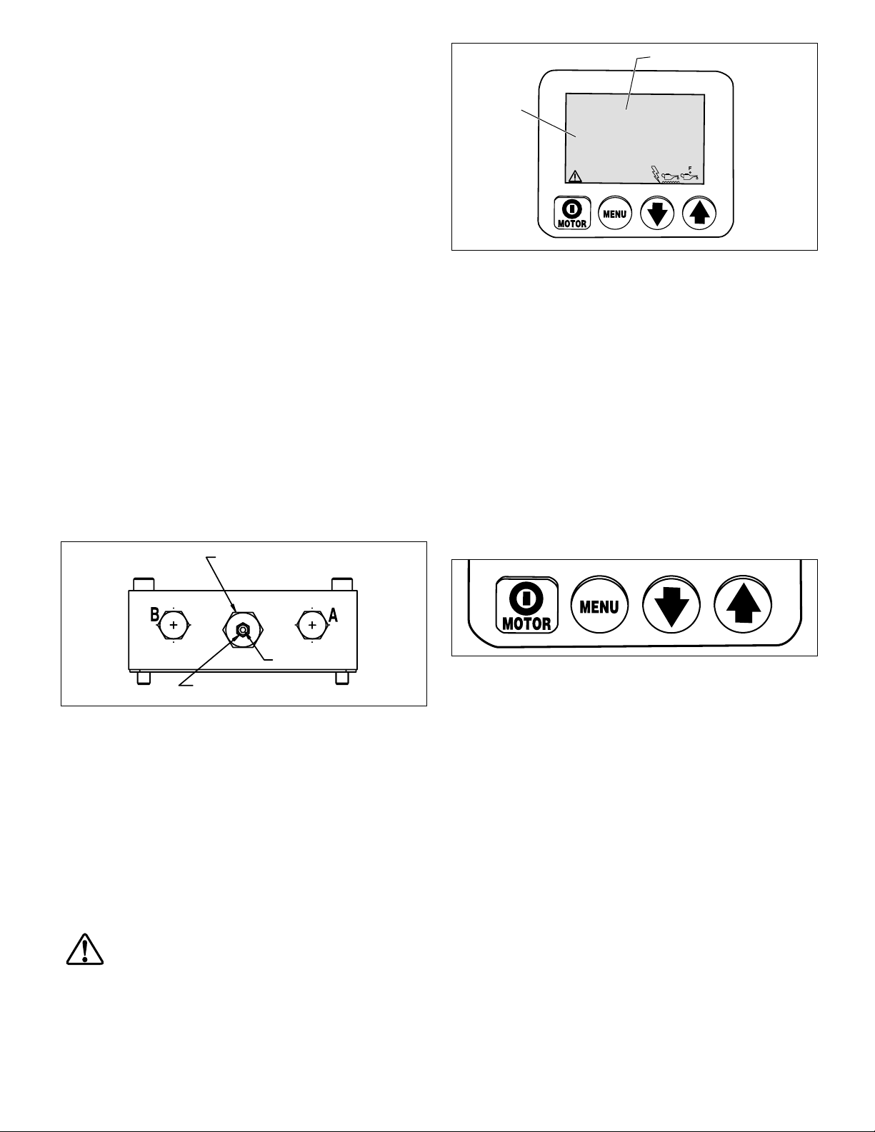
Text Display
Numeric
Display
6.2 Boot Sequence
When the pump is connected to electrical power, the LCD screen
will show: “FIRMWARE 7.x” for 1 second, then “Model XX” for
0.5 seconds. Following these messages, “Motor UN”, “Motor
1P” or “Motor 3P” will appear for 0.5 seconds. This information
may be useful if the pump ever requires servicing or repairs.
Additional information may appear, depending on pump model
and installed accessories.
The boot sequence is successfully completed when the text
display on the LCD screen shows “READY” (sequence takes
approximately 3 seconds). On pumps equipped with the pressure
transducer option, the current system pressure (typically “0” if
motor is not running) will also appear on the numeric display.
SET
00000000
0000.0
HOURS CYCLES
LOW MOTOR
VOLTAGE OVERLOAD
Figure 6, LCD Control Panel
PSI MPa
BAR
6.3 LCD Operation Buttons
The LCD control panel is equipped with four button switches:
Set Screw
Locknut
Figure 5, Relief Valve
6.0 LCD ELECTRONIC CONTROLS
6.1 LCD Control Panel Overview
The LCD control panel serves as an interface between the
operator and the pump. By using the LCD control panel's fourbutton switches, and the additional button switches located on
the pendant, all functions and settings described in sections 6.3
through 6.6 of this document can be activated.
In the event of an abnormal condition, the LCD also displays
fault codes and warning alerts as described in sections 6.7 and
6.8.
CAUTION: Make sure that the plastic overlay that
protects the LCD screen and the button switches is
not broken or otherwise damaged. Never punch the
button switches with a sharp or pointed instrument, use fi ngertips
only. Clean the overlay regularly with a damp cloth. Never use
aggressive or abrasive detergents.
On/Off / Menu / Down Arrow / Up Arrow
• Pressing the MOTOR on/off button shuts-off the motor during
normal operation. The motor OFF function is available on this
button even if the pump is being operated by the pendant.
However, the MOTOR on/off button will not turn the motor
ON except if the LCD is in Local mode (See section 6.5 K).
• Pressing the MENU button enables the operator to step from
normal operational mode into a series of menus. Repeated
pressing allows the operator to step through all available
menus. Pressing the Menu button also saves any changes
made. To return to the normal operational mode, press and
hold the Menu button for three seconds or do not push any
button for 60 seconds.
• The Down Arrow and Up Arrow buttons serve two purposes.
For most LCD menus, the Down Arrow and Up Arrow buttons
are used to step through the menu options. Also, when the
pump is placed in Local mode, pressing the Up Arrow button
switches the valve solenoid on and off (the pendant is nonoperational in Local mode).
4
6.4 LCD Menu Overview
The LCD contains the following available menus:
• Normal Operation – Default start-up screen. Appears
immediately after power is connected and microcontroller
has booted.
Note: The Units, Automode, Hi Press and Lo Press menus are
available only on pumps equipped with a pressure transducer
(optional equipment)
• Units – Sets the pressure units to PSI / BAR / MPa. PSI is the
default setting.
• Automode – Switches the Automode function ON or OFF.
• Hi Press – (Available only when Automode is ON) Sets the high
pressure limit at which pump de-energizes motor / electric
valve.
• Lo Press – (Available only when Automode is ON - Not used
on pump type 3) Sets the low pressure limit at which pump
energizes motor / electric valve.
• Main – Displays pump status after the desired pump
operational parameters have been input by the user and
saved in the microcontroller memory.
• Motor – Displays the motor hour meter and on/off cycle
counter (non-resettable).
• Low Volt – Displays the low voltage hour meter
(non-resettable).
• Advance – Displays the solenoid hour meter and on/off cycle
counter for the advance solenoid (non-resettable).
• Retract – Displays the solenoid hour meter and on/off cycle-
counter for the retract solenoid (non-resettable).
• Local – Switches the pump Local mode ON or OFF.
• Language – Sets the language of the display to English,
Spanish, French, Italian, German or Portuguese, with English
being the default setting.
• Diagnose – Displays input signals from the pendant and other
electrical accessories.
6.5 LCD Menus
See the following paragraphs for descriptions of the LCD menus.
Also refer to Table 2, Quick Reference Chart (QRC), located at the
end of this document.
6.5 A Normal Operation Menu
(See Screen 1) LCD screen “READY”
indicates that the microcontroller has
booted successfully.
For pumps equipped with a pressure
transducer, the pressure reading will
be displayed as “0” when pump is
fi rst connected to power and motor is
off. Enter into the remaining menus by
pressing the Menu button. Refer to QRC step #1.
6.5 B “Units” Menu
(See Screen 2) This screen allows the
operator to set the unit of pressure
measurement by pressing the Up or
Down Arrow buttons. PSI, BAR and
Mpa are the available choices, with
PSI being the default. Save setting
and step forward by pressing the
Menu button. Refer to QRC step #2.
Screen 1
READY
PSI
0
Screen 2
SET
PSI MPa
UNITS
BAR
6.5 C “Automode” Menu
(See Screen 3) This screen allows the
operator to activate or de-activate
automatic operation of the pump
motor and electric valve (if equipped).
Toggle Automode ON or OFF by
pressing either the Up or Down Arrow
button. Save setting and step forward
by pressing the Menu button. Refer to QRC step #3A.
Notes:
• The UNITS and AUTOMODE menus are available only on
pumps equipped with the pressure transducer option. These
menus will not appear on pumps not equipped with a pressure
transducer.
• When Automode is on, the pump will de-energize the motor
/ electric valve when the hydraulic pressure reaches operator
defi ned levels. This parameter is set using the Automode “HI
PRESS” menu.
• The pump can be set to re-energize the motor / electric valve
when the hydraulic pressure falls to an operator defi ned level.
This parameter is set using the Automode “LO PRESS” menu.
Note: the LO PRESS menu is not functional for pump type 3.
• The specifi c operation of the motor and electric valve while
Automode is activated is determined by the pump type (factory
set). For additional information, refer to Table 4, Pump Model
Matrix, located at the end of this document. Also refer to sections
4.0 and 4.1 for an overview of Automode operation.
• If Automode is OFF: The HI PRESS and LO PRESS menus will
not be available, and any previously set HI or LO PRESS values
will have no effect on pump operation.
Screen 3
SET
AUTOMODE
ON
6.5 D “HI PRESS” Menu
(Available only when Automode is ON)
(See Screen 4) This screen allows the
operator to set the high-pressure limit
at which the pump de-energizes the
motor / electric valve. Make changes
in increments of 50 psi [3.5 bar] by
pressing either Down or Up Arrow
button once. Press and hold either
button to scroll quickly through the
available settings. Maximum pressure value is 10,500 psi [724
bar]. Save setting and step forward to the Main menu (See
section 6.5 F) by pressing the Menu button for 3 seconds. Refer
to QRC step #3B.
Note: If the menu button is pressed for less than 3 seconds, the
selected HI PRESS value will be saved and the LO PRESS menu
(See section 6.5 E) will appear.
CAUTION: Due to motor coast down, valve shift time
and system oil capacitance, always set the user-
adjustable relief valve 200 psi above the HI PRESS
value to prevent pressure spikes. Refer to pump instruction
sheet for relief valve setting instructions.
Screen 4
SET
HI PRESS
7500
PSI
5

6.5 E “LO PRESS” Menu (Available only when
Automode is ON - All except pump type 3)
(See Screen 5) This screen allows
the operator to set the low-pressure
limit at which the pump energizes the
motor / electric valve. Make changes
in increments of 50 psi [3.5 bar] by
pressing either Down or Up Arrow
button once. Press and hold either
button to scroll quickly through the
available settings. Default pressure value is OFF (or “0” on some
pump models). Save setting and step forward to the Main menu
(See section 6.5 F) by pressing the Menu button for 3 seconds.
Refer to QRC step #3C.
Note: If the menu button is pressed for less than 3 seconds, the
selected LO PRESS setting will be saved. However, the Motor
menu (See section 6.5 G) will appear instead of the Main menu.
CAUTION: The LO PRESS value should be set at least
400 PSI below the HI PRESS value to prevent excessive
pump cycling. Use appropriate valving in the hydraulic
circuit to ensure that the pump does not cycle on and off more
than three times per minute. For circuits equipped with sequence
valves, the LO PRESS setting should be at least as high as the
fi rst stage sequence valve pressure.
6.5 F Main Menu
(See Screen 6A) When Automode is
fi rst turned on, the screen will display
“AUTO”.
(See Screen 6B) During pump
operation, and after Automode has
taken control of the pump, the text will
change from “AUTO” to “AUTO ON”.
All except pump type 3: If a LO
PRESS value has been entered, the
pump backlight will begin to fl ash on
and off. This fl ashing will continue
until system pressure drops to the LO
PRESS value.
Note: Details of Automode operation
will vary, depending on pump type and
model. Refer to sections 4.0 and 4.1
for additional information. Also refer to
the pump model matrix in Table 4 near
the end of this document.
(See Screen 6C) If Automode is OFF, the
screen will display “READY” instead of
“AUTO”, and the system pressure will
appear on the numeric display.
Note: For pumps NOT equipped with
a pressure transducer, the screen will
display “READY” and no pressure will
be indicated. The “AUTO” and “AUTO
ON” screens will not be available.
6.5 G “Motor” Menu
(See Screen 7) This screen allows the
operator to read the number of hours
or on/off cycles the motor has been
operated. Toggle between hours and
cycles by pushing either the Down
or Up Arrow button. Step forward by
pressing the Menu button. Refer to
QRC step #5.
Screen 5
SET
LO PRESS
OFF
Screen 6A
AUTO
0
Screen 6B
AUTO ON
0
Screen 6C
READY
0
Screen 7
MOTOR
4.8
HOURS CYCLES
PSI
PSI
PSI
__________________________________________________________
General note for all hour and cycle displays:
HOURS DISPLAYED
- up to 9999.9 the display will show decimal hours.
- between 10,000 - 99,999 whole hours will be
displayed (decimal “.” is not displayed).
- over 99,999 hours the meter starts over at 0.0 reading
decimal hours.
CYCLES DISPLAYED
- over 99,999 cycles the meter starts over at 0.
__________________________________________________________
6.5 H “Low Volt” Menu
(See Screen 8) This screen allows the
operator to read the number of hours
the pump has been operated in a lowvoltage condition. Step forward by
pressing the Menu button. Refer to
QRC step #6.
6.5 I “Advance” Menu
(See Screen 9) This screen allows the
operator to read the total number of
hours that the advance valve solenoid
has been operated. It also displays
the total number of advance solenoid
cycles. Toggle between hours and
cycles by pushing either the Down or
Up Arrow buttons. Step forward by
pressing the Menu button. Refer to
QRC step #7.
6.5 J “Retract” Menu
(See Screen 10) This screen allows
the operator to read the total number
of hours that the retract solenoid has
been operated. It also displays the
total number of retract solenoid cycles.
Toggle between hours and cycles by
pushing either the Down or Up Arrow
buttons. Step forward by pressing the
Menu button. Refer to QRC step #8.
6.5 K “Local” Menu
(See Screen 11) This screen allows the
operator to toggle the Local mode ON
or OFF (default is OFF). Local mode
allows operation of the pump if the
pendant or pendant cord is damaged.
With Local mode ON, the shroud
buttons replace the pendant buttons
as the method of operating the pump,
and the pendant buttons become deactivated. Toggle Local
mode ON or OFF by pressing the Down or Up Arrow button.
When Local mode is ON, the text “LOCAL” replaces “READY” on
the “Normal Operation” menu. Save setting and step forward by
pressing the Menu button. Refer to QRC step #9.
6
Screen 8
LOW VOLT
.0
HOURS
Screen 9
ADVANCE
188
HOURS CYCLES
Screen 10
RETRACT
334
HOURS CYCLES
Screen 11
SET
LOCAL
OFF

6.5 L “Language” Menu
(See Screen 12) This screen allows
the operator to change the LCD display
language. When a language is shown on
the LCD, press the Down or Up Arrow
buttons to select a different language. Save
setting and step forward by pressing the
Menu button. Refer to QRC step #10.
6.5 M “Diagnose” Menu
(See Screen 13) This screen allows
the operator to troubleshoot various
pendant problems. If the number “1”
does not appear when a pendant button
is pushed, problems with the pendant
button switches and/or pendant cord
may be present (See Screens 14, 15 and
16). Use Local mode to operate pump
until problem can be corrected. Refer to
QRC step #11.
Pendant on/off button
Pendant advance button
Pendant retract button
(not used)
(not used)
Diagnose screen
with pendant
on/off button
pushed.
Press
Screen 12
SET
ENGLISH
Screen 13
DIAGNOSE
PSI MPa
PSI MPa
BAR Nm
Ft-lb
BAR Nm
Ft-lb
00001
Screen 14
DIAGNOSE
01001
6.6 LCD Hidden Menus
6.6 A “Calibration” Menu
(See Screen 17) This screen allows the
operator to adjust the pressure value
shown on the LCD to match a master
gauge.
To access this menu, go to the “UNITS”
menu.
Then, press and hold the shroud
Motor on/off button in for 7 seconds. ENTRY CODE will appear.
Then, press and hold both the Down Arrow and Up Arrow button
for 7 seconds. See Table 3, “Z-Class Pressure Transducer
Calibration” for adjustment steps.
Screen 17
SET
CAL PT A
0
PSI
6.7 LCD Fault Conditions
Any fault condition will shut down the pump and prevent it from
starting.
6.7 A Clearing a Fault Condition from the LCD
After the fault causing problem has been corrected, clear the fault
message from the LCD by disconnecting electrical power from
the pump. Wait until all characters clear the LCD (~ 10 seconds),
then reconnect power.
6.7 B Power Failure
Display: “POWER OFF”
(See Screen 18) The Power Off fault is
displayed when the main power supply
drops to 65% or less of nominal voltage.
The pump will automatically shut-off
the valve solenoid and the motor, and
display “Power Off” on the LCD. Note:
Power Off is also displayed for several
seconds after the unit is disconnected
from electrical power.
Screen 18
POWER
OFF
Diagnose screen
with pendant
advance button
.
pushed
Diagnose screen
with pendant
retract button
.
pushed
Press
Press
Screen 15
DIAGNOSE
10001
Screen 16
DIAGNOSE
00101
PSI MPa
BAR Nm
Ft-lb
PSI MPa
BAR Nm
Ft-lb
6.7 C Button Fault
Display: “BUTTON FAULT”
(See Screen 19) The Button Fault
message is displayed when the
microcontroller detects that any button
is pressed during the boot sequence
or if the shroud Motor on/off button is
pressed for more than 3 seconds.
Screen 19
BUTTON
FAULT
6.7 D Motor Overload
Display: “MTR OVLD” and
“Motor Overload”
(See Screen 20) The Motor Overload
fault is displayed when the electric
current draw exceeds the pre-set limit
of the pump’s internal circuit breaker.
The circuit breaker will automatically
reset in about 2 to 3 minutes after the
condition has been corrected. However,
before the pump can be restarted, the
operator must clear the fault by disconnecting and reconnecting
electrical power as described in section 5.7 A.
Screen 20
MTR OVLD
MOTOR
OVERLOAD
7

6.7 E Oil Level
(requires optional fl oat / temperature switch)
Display: “OIL LEVEL”
(See Screen 21) The Oil Level fault is
displayed when the oil level inside the
reservoir drops below 1.3" (34 mm)
from bottom.
Screen 21
OIL LEVEL
6.8 LCD Warning Conditions
LCD Warnings notify the operator of abnormal operating
conditions, but allow the pump to continue operating. Warnings
will automatically clear once the abnormal condition has been
resolved.
6.8 A Low Voltage Warning
Display: “LOW VOLT” and “Low Voltage”
6.7 F Oil Temperature
(requires optional fl oat/temperature switch)
Display: “OIL TEMP”
(See Screen 22) The Oil Temperature
fault is displayed when the temperature
of the oil inside the reservoir exceeds
175 ºF [80 °C].
Screen 22
OIL TEMP
6.7 G Oil Pressure
(requires optional pressure switch)
Display: “P SWITCH OPEN”
(Screen 23) The “P SWITCH OPEN”
fault is displayed when the high pressure
limit is reached and the pressure switch
opens.
Screen 23
P SWITCH
OPEN
(See Screen 23) A “Low Voltage”
condition is defi ned as an operating
condition when the main power supply
is at or below 80% of nominal voltage.
While running the pump under this
condition, the “Low Voltage” signal will
fl ash on the LCD and the Low Voltage
hours will be counted and stored by the
microcontroller. Normal pump operation
is still permitted.
IMPORTANT: Pump operation during a Low Voltage condition
is not recommended. Motor RPM and hydraulic fl ow will be
reduced. The pump's internal circuit breaker may trip due to high
current draw, resulting in a Motor Overload fault (see section
6.7 D).
Screen 24
LOW VOLT
LOW
VOLTAGE
Pressure Switch Notes:
• The pressure switch does not provide real time pressure data
to the LCD. For this reason, no pressure indication will be shown
on the “READY” screen unless a pressure transducer is also
installed.
• Factory installed pressure switches are typically installed in the
valve manifold “GA” port. However, if desired, the pressure switch
can be installed in the valve manifold “GB” or “GP” ports.
“GA” measures “A” port pressure.
“GB” measures “B” port pressure (if applicable).
“GP” measures pump pressure before the control valve.
8

(Continued on next page)
Units Comments
digital display
Start calibration process.
PSI, BAR or MPa. Default is PSI.
Firmware version 7.x, pump type (1, 2, 3, 6, 8 or 10)
and motor type (UN, IP or 3P) will briefl y appear on LCD.
or MPa
Save previous setting and step forward to select units,
“READY” appears after power on and boot sequence has completed.
PSI, BAR or MPa. Default is PSI.
Toggle between “ON” and “OFF” using the Arrow buttons.
See Table 2, calibration reference chart for further instructions.
or MPa
Note: To step to #5 Motor screen, turn Automode OFF
If Automode is ON.
and press Menu button.
default value is 10,500 psi [724 bar].
Set maximum pressure (upper Automode limit),
Note: Pressure not adjustable when Automode is OFF.
or MPa
PSI, BAR
If Automode is ON.
default value is OFF.
hold down button for 4 sec. minimum.
hold down button for 4 sec. minimum.
Set minimum pressure (lower Automode limit),
" Only if pressure transducer is detected,
" Only if pressure transducer is detected,
or MPa
PSI, BAR
hold down button for 4 sec. minimum.
Note: Pressure not adjustable when Automode is OFF.
" Only if pressure transducer is detected,
hold down button for 4 sec. minimum.
" Only if pressure transducer is detected,
Expected reading / symbol / status
Display
Table 2, QRC: Quick Reference Chart • Pump Firmware Version 7.x • Pump Types 1, 2, 3, 6, 8 and 10
Step Switch Text
1 READY 0 PSI, BAR,
2A X SET UNITS PSI
X" BAR
X" MPa
X Save and step to #3 by pressing Menu button.
CAL PT A 0 PSI, BAR,
X X " Hold for 7 Seconds
2B X SET UNITS Hold for 7 Seconds Save previous setting and step forward to select units,
XXXXX (PSI, BAR or MPa)
Then up 50 psi [4 bar] every 0.05 sec.
Then down 50 psi [4 bar] every 0.05 sec.
HI PRESS
X " Up 50 psi [4 bar] per 0.5 sec. for fi rst 3 sec.
XON
X Save and step to #3B by pressing Menu button.
3A X AUTOMODE OFF
9
3B SET
X " Down 50 psi [4 bar] per 0.5 sec. for fi rst 3 sec.
X Save and step to #3C by pressing Menu button.
3C SET
XXXXX (PSI, BAR or MPa)
Then up 50 psi [4 bar] every 0.05 sec.
Then down 50 psi [4 bar] every 0.05 sec.
LO PRESS
X " Up 50 psi [4 bar] per 0.5 sec. for fi rst 3 sec.
X " Down 50 psi [4 bar] per 0.5 sec. for fi rst 3 sec.
X Save and step to #5 by pressing Menu button.

Text Display:
Units Comments
digital display
“AUTO” if Automode ON
“READY” if Automode OFF
Select hour meter function (motor).
Select cycle counter function (motor).
Numeric display will show “0” when system pressure is zero.
or MPa
PSI, BAR
0 PSI
0 BAR
0 MPa
Select “LOCAL” mode.
Toggle between “ON” and “OFF”.
Pressure or torque units will appear,
indicating that pressure transducer is connected.
When pendant buttons are pushed, the digital display
is expected to show processor inputs that are “turned on”.
MPa,
10001 With pendant On/Off button pushed.
01001 With pendant ADVANCE button pushed.
00101 With pendant RETRACT button pushed.
Expected reading / symbol / status
Display
Table 2, QRC: Quick Reference Chart • Pump Firmware Version 7.x • Pump Types 1, 2, 3, 6, 8 and 10
(Continued from previous page)
Step Switch Text
or
4 AUTO
READY
X " Number of cycles. CYCLES Select cycle counter function (solenoid advance).
X " Number of cycles. CYCLES Select cycle counter function (solenoid retract).
X" ON
X " Number of cycles. CYCLES
6 X LOW VOLT Number of hours at low voltage, displayed as 0.0. HOURS Select hour meter function (low voltage condition).
7 X ADVANCE Number of hours, displayed as 0.0. HOURS Select hour meter function (solenoid advance).
5 X MOTOR Number of hours 0.0. HOURS
8 X RETRACT Number of hours, displayed as 0.0. HOURS Select hour meter function (solenoid retract).
X " OFF
9 X LOCAL OFF
X ESPANOL
X FRANCAIS
X ITALIANO
X DEUTSCH
X PORTUGUES
X ENGLISH Save and step to #11 with Menu button.
10 X ENGLISH Select language, default is English.
10
11 X DIAGNOSE 00001 PSI, BAR, or
12 X - - - Hold for 3 seconds to return to step 4.

Comments
LCD Reading
Boot sequence.
psi is the current unit of pressure measurement.
0 psi
psi
FIRMWARE 7.x,
then “READY”
UNITS
Table 3 , Z-Class Pressure Transducer Calibration, Firmware 7.x • Pump Types 1, 2, 3, 6, 8 and 10
Step into the hidden calibration mode.
Start of calibration process. The advance-solenoid will be powered up to access the pressure transducer
CODE
O psi
ENTRY
CAL PT A
through valve-port A.
[O bar]
Calibrate the zero-offset, point “A”.
O psi
[O bar]noyes
CAL PT A
SAVE A
Confi rm the pressure data should be stored to memory.
SAVE A
Calibrating gain is done with two points, starting with point “B”.
5000 psi
[345 bar]
CAL PT B
First obtain the pressure value on the master gauge (ie 5000 psi). Then use the arrow buttons to match the
LCD value to the master gauge.
5000 psi
[345 bar]noyes
CAL PT B
SAVE B
Confi rm the pressure data should be stored to memory.
SAVE B
Calibrating gain is done with two points, fi nishing with point “C”.
8000 psi
[548 bar]
CAL PT C
First obtain the pressure value on the master gauge (ie 8000 psi). Then use the arrow buttons to match the
LCD value to the master gauge.
8000 psi
[548 bar]noyes
CAL PT C
SAVE C
Confi rm the pressure data should be stored to memory.
SAVE C
Re-confi rm calibration data. Leave “off” to proceed with new calibration data. Only set to “on” to change
off
USE DFLT
calibration data back to factory default settings. Press Arrow button to change.
Save calibration data to permanent memory.
Calibration complete, motor stops and electric valve releases pressure.
O psi
[O bar]
O psi
CAL PT A
READY
[O bar]
Operator action
No.
Connect a master gauge to port A (Advance port)
1
Connect electrical power to pump.
At main screen, press the Menu button once to display “UNITS” screen.
2
3
Press and hold the ON/OFF button for seven seconds.
Press and hold the Arrow-up and Arrow-down buttons together for seven seconds.
Open the pump’s user-adjustable relief valve and verify both pump LCD and master
gauge read zero.
Press the Menu button to accept the pressure value into temporary memory.
Press one Arrow button to change from “no” to “yes”.
Press the Menu button once.
Press and release the shroud’s ON/OFF motor-button to switch the pump motor on.
Reading the master gauge, apply a pressure of 5000 psi by closing the pump’s user-
4
5
6
7
8
9
10
adjustable relief valve.
Press the Menu button to accept the pressure value into temporary memory.
Press one Arrow button to change from “no” to “yes”.
11
12
11
Press the Menu button once.
Reading the master gauge, apply a pressure of 8000 psi.
Press the Menu button to accept the pressure value into temporary memory.
Press one Arrow button to change from “no” to “yes”.
13
14
15
16
Press the Menu button once.
Press the Menu button once.
Press and hold the Menu button for three seconds to step out of the calibration mode.
17
18
19

Additional comments
3 button pendant used but only Up and Down
Arrow buttons are active
up-arrow now on the middle button-position,
using pin #2 of pendant
Pump type 6 is the default factory setting. 0
means LO_PRES is turned off. Default
manufacturer setting is AUTO MODE off &
LO_PRESS is 0
safety feature: Arrow-up and arrow-down
buttons switch off motor when pump is running
on toggle-on
(Continued on next page)
turned off.
On/Off
value. 0 means LO_PRESS is
50 psi less than HI_PRESS current
on
10,500 psi
off
on/off
toggle
na -
no pendant
50 psi less than HI_PRESS current
on
10,500 psi
off
off
(advance)
momentary on
Max value for LO_PRESS
value is reached
Action when LO_PRESS
Operation with Automode ON
Max value
for HI_PRESS
Pumps Equipped with Pressure Transducer Option Only
Action when HI_PRESS
value is reached
LCD Panel
Button
Motor
Arrow up
na - can not change
LO_PRESS value from off
off
off
(advance)
momentary on
na
na
10,500 psi
only the valve shuts off,
when HI_PRESS is reached
on/off
toggle
no change
50 psi less than HI_PRESS current
on
off
motor continues running
off
momentary on
turned off.
value. 0 means LO_PRESS is
na
off
off
na - disabled
value from off
na - can not change LO_PRESS
na - can not change
LO_PRESS value from off
10,500 psi
off
off
(advance)
momentary on
turned off
value. 0 means LO_PRESS is
(advance)
na
turned off.
value. 0 means LO_PRESS is
50 psi less than HI_PRESS current
off
on
10,500 psi
off
off
off
off
toggle
on/off
momentary on
Pendant Button
What happens when _____ button is pushed in
normal operation mode (“READY” is displayed on LCD)
Table 4, Z-Class Pump Model Matrix • Firmware 7.x • Pump Types 1, 2, 3, 6, 8 and 10
down
Arrow
Motor
On/Off
Item
foot
switch
pendant
valve
code
Pump type
type
Pump
Type
Pump
na -
no pendant
no
na -
(if attached)
Motor & Fan
NA
none
any manual
ZxxxxxLx
ZxxxxxHx
w/LCD
manual
1
pendant
na - disabled
na -
disabled
(if attached)
Motor & Fan
Option
3-button
VE32
Zxx2xxSx
Adv /
Hold /
2
Ret
momentary
na -
Solenoid B
on (retract)
na - disabled
na -
disabled
Motor & Fan
Option
1-button
VE32-D
Zxx1xxDx
Dump
3
disabled
(if attached)
12
na - disabled
na -
disabled
Solenoid A
no change
on/off
toggle
(if attached)
Motor & Fan
Option
3-button
VE33 / VE43
Zxx3xxSx
Zxx4xxSx
remote
3/4-way
6
off
no
change
Solenoid A
none
none
ZxxxxxWx
momentary
no
Solenoid B
on (retract)
change
on
momentary
on/off
toggle
(if attached)
Motor & Fan
Option
button
1or2-
any manual
8 Jog ZxxxxxKx

Additional comments
Similar to pump No. 6 execpt that LOCAL MODE
is the default at start-up. Pendant buttons are
disabled.
(See Note 2)
na
Max value for LO_PRESS
na
value is reached
Action when LO_PRESS
Operation with Automode ON
Max value
for HI_PRESS
Pumps Equipped with Pressure Transducer Option Only
reached
(SET_PRESS) value is
Action when HI_PRESS
Button
LCD Panel
Motor
Arrow up
On/Off
10,500 psi
when HI_PRESS is reached
toggle
no change
only the valve shuts off,
on/off
motor continues running
50 psi less than HI_PRESS current
on
off
off
(see note 1)
momentary on
turned off
value. 0 means LO_PRESS is
(advance)
na
off
off
off
off
be on or off
Note: Motor may
Notes - Pump Type 10:
1. if Automode is OFF, motor is momentary on (no toggle).
2. If Automode is OFF, solenoids can be operated manually when motor is off or on.
What happens when _____ button is pushed in
normal operation mode (“READY” is displayed on LCD)
Table 3, Z-Class Pump Model Matrix • Firmware 7.x • Pump Types 1, 2, 3, 6, 8 and 10
Table 4, Z-Class Pump Model Matrix • Firmware 7.x • Pump Types 1, 2, 3, 6, 8 and 10
(Continued from previous page)
Pendant Button
down
Arrow
Motor
On/Off
Item
foot
switch
pendant
valve
code
Pump type
type
Pump
Type.
Pump
no change
On
(no toggle)
Momentary
(if attached)
Motor & Fan
Option
3-button
VE33 / VE43
ZxxxxxWx
Manual
Momen-
tary
10
Pump
off
no
Solenoid A
none
none
change
13
momentary
no
Solenoid B
(retract)
on
change
may be
on or off
Note: Motor

Enerpac Worldwide Locations
Africa
ENERPAC Middle East FZE
Office 423, JAFZA 15
P.O. Box 18004
Jebel Ali, Dubai
United Arab Emirates
Tel: +971 (0)4 8872686
Fax: +971 (0)4 8872687
Australia, New Zealand
Actuant Australia Ltd.
Block V Unit 3
Regents Park Estate
391 Park Road
Regents Park NSW 2143
(P.O. Box 261) Australia
Tel: +61 297 438 988
Fax: +61 297 438 648
Brazil
Power Packer do Brasil Ltda.
Rua dos Inocentes, 587
04764-050 - Sao Paulo (SP)
Tel: +55 11 5687 2211
Fax: +55 11 5686 5583
Toll Free in Brazil:
Tel: 0800 891 5770
vendasbrasil@enerpac.com
Canada
Actuant Canada Corporation
6615 Ordan Drive, Unit 14-15
Mississauga, Ontario L5T 1X2
Tel: +1 905 564 5749
Fax: +1 905 564 0305
Toll Free:
Tel: +1 800 268 4987
Fax: +1 800 461 2456
Technical Inquiries:
techservices@enerpac.com
China
Actuant Industries Co. Ltd.
No. 6 Nanjing Road
Taicang Economic Dep Zone
Jiangsu, China
Tel: +86 0512 5328 7529
+86 0512 5328 7500 7529
Fax: +86 0512 5335 9690
Actuant China Ltd. (Beijing)
709B Diyang Building
Xin No. 2
Dong San Huan North Rd.
Beijing City
100028 China
Tel: +86 10 845 36166
Fax: +86 10 845 36220
e-mail: info@enerpac.com
&
Central and Eastern Europe, Greece
ENERPAC GmbH
P.O. Box 300113
D-40401 Düsseldorf
Willstätterstrasse13
D-40549 Düsseldorf
Germany
Tel: +49 211 471 490
Fax: +49 211 471 49 28
France, Switzerland francophone
ACTUANT - ENERPAC
France S.A., ZA de Courtaboeuf
32, avenue de la Baltique
91140 Villebon / Yvettte
France
Tel: +33 1 60 13 68 68
Fax: +33 1 69 20 37 50
Germany, Austria
and Switzerland and Baltic States
ENERPAC GmbH
P.O. Box 300113
D-40401 Düsseldorf
Willstätterstrasse13
D-40549 Düsseldorf
Germany
Tel: +49 211 471 490
Fax: +49 211 471 49 28
India
ENERPAC Hydraulics
(India) Pvt. Ltd.
No. 1A,
Peenya Industrial Area,
llnd Phase
Bangalore, 560 058 India
Tel: +91 80 40 792 777
Fax: +91 80 40 792 792
Italy
ENERPAC S.p.A.
Via Canova 4
20094 Corsico (Milano)
Tel: +39 02 4861 111
Fax: +39 02 4860 1288
Japan
Applied Power Japan LTD KK
Besshochou 85-7
Kita-ku,
Saitama-shi 331-0821
Japan
Tel: +81 48 662 4911
Fax: +81 48 662 4955
Middle East, Turkey and
Caspian Sea
ENERPAC Middle East FZE
Office 423, JAFZA 15
P.O. Box 18004
Jebel Ali, Dubai
United Arab Emirates
Tel: +971 (0)4 8872686
Fax: +971 (0)4 8872687
Russia and CIS
(excl. Caspian Sea Countries)
Actuant LLC
Admiral Makarov Street 8
125212 Moscow, Russia
Tel: +7-495-9809091
Fax: +7-495-9809092
Sweden, Denmark, Norway,
Finland and Iceland
ENERPAC Scandinavia AB
Fabriksgatan 7
412 50 Gothenburg
Sweden
Tel: +46 31 7990281
Fax: +46 31 7990010
Singapore
Actuant Asia Pte. Ltd.
37C, Benoi Road Pioneer Lot,
Singapore 627796
Tel: +65 68 63 0611
Fax: +65 64 84 5669
Toll Free: +1800 363 7722
Technical Inquiries:
techsupport@enerpac.com.sg
South Korea
Actuant Korea Ltd.
3Ba 717,
Shihwa Industrial Complex
Jungwang-Dong, Shihung-Shi, Kyunggi-Do
Republic of Korea 429-450
Tel: +82 31 434 4506
Fax: +82 31 434 4507
Spain and Portugal
ENERPAC SPAIN, S.L.
Avda. Los Frailes, 40 – Nave C & D
Pol. Ind. Los Frailes
28814 DAGANZO DE ARRIBA (Madrid)
Spain
Tel: +34 91 661 11 25
Fax: +34 91 661 47 89
&
internet: www.enerpac.com
The Netherlands, Belgium,
Luxembourg
ENERPAC B.V.
Galvanistraat 115, 6716 AE Ede
P.O. Box 8097, 6710 AB Ede
The Netherlands
Tel: +31 318 535 800
Fax: +31 318 525 613
+31 318 535 848
Technical Inquiries Europe:
techsupport.europe@enerpac.com
United Kingdom, Ireland
Enerpac Ltd
Bentley Road South
Darlaston, West Midlands
WS10 8LQ, United Kingdom
Tel: +44 (0)121 50 50 787
Fax: +44 (0)121 50 50 799
USA, Latin America
and Caribbean
ENERPAC
P.O. Box 3241
6100 N. Baker Road
Milwaukee, WI 53209 USA
Tel: +1 262 781 6600
Fax: +1 262 783 9562
User inquiries:
+1 800 433 2766
Inquiries/orders:
+1 800 558 0530
Technical Inquiries:
techservices@enerpac.com
ENERPAC
704 W. Simonds
Dallas, TX 75159 USA
Tel: +1 972 287 2390
Fax: +1 972 287 4469
All Enerpac products are guaranteed against defects in workmanship and materials for as long as you own them.
For your nearest authorized Enerpac Service Center, visit us at www.enerpac.com
062609
 Loading...