

Instruction Sheet
POWERFUL SOLUTIONS. GLOBAL FORCE.
L4242 Rev. B 10/18
ZC-Series Cordless Electric Pumps
EN
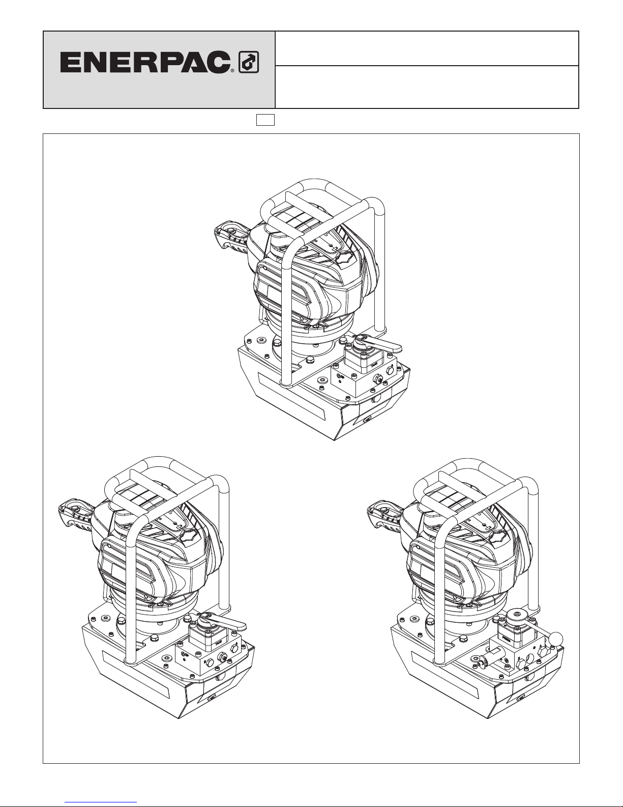
ZC3308J
ZC3408J ZC3908J

TABLE OF CONTENTS:
1.0 SAFETY .........................................................................................3
1.1 Introduction ......................................................................3
1.2 General Hydraulic Safety Precautions ...........................3
1.3 Battery Operated Pump Safety Precautions .................4
2.0 MAJOR FEATURES AND COMPONENTS ..................................5
3.0 PRODUCT DATA ........................................................................... 6
3.1 Specifications ..................................................................6
3.2 Pressure and Flow Graphs ..............................................6
3.3 External Dimensions .......................................................7
4.0 PRODUCT DESCRIPTION ...........................................................8
4.1 Introduction ......................................................................8
4.2 Additional Information - Battery and Charger ..............8
4.3 Conformance to National and International Standards ..8
4.4 Electromagnetic Compatibility (EMC) ..........................8
5.0 IMPORTANT RECEIVING INSTRUCTIONS ................................8
5.1 Hydraulic Reservoir Breather .........................................8
6.0 HYDRAULIC CONNECTIONS......................................................8
7.0 BATTERY ......................................................................................9
7.1 Battery Capacity Indicator ..............................................9
7.2 Battery Installation ..........................................................9
7.3 Battery Removal ............................................................10
7.4 Battery Management System .......................................10
7.5 Additional Battery and Charger Information ...............10
8.0 OPERATION ................................................................................ 10
8.1 Before Start-up ..............................................................10
8.2 Starting the Pump Motor ..............................................10
8.3 Stopping the Pump Motor .............................................10
8.4 Operating Precautions ..................................................10
8.5 Manual Valve Operation ................................................10
8.5.1 VM33 Operation ..........................................................10
8.5.2 VM43 Operation ..........................................................11
8.5.3 VM43LPS Operation
(post-tensioning applications only) ...........................11
8.6 Air Removal ....................................................................11
8.7 Disconnecting Hydraulic Hoses ...................................12
8.8 Transporting the Pump ..................................................12
9.0 MAINTENANCE ..........................................................................12
9.1 Check Oil Level ..............................................................12
9.2 Hydraulic Oil Information ..............................................12
9.3 Adding Oil .......................................................................12
9.4 Oil Change ......................................................................12
10.0 PRESSURE RELIEF VALVE ADJUSTMENT ............................13
10.1 VM33 and VM43 Only ...................................................13
10.2 VM43LPS Only ..............................................................13
11.0 TROUBLESHOOTING ..............................................................14
Troubleshooting Guide .....................................................................14
1.0 SAFETY
WARNING
NOTICE
1.1 Introduction
Read all instructions carefully. Follow all recommended safety
precautions to avoid personal injury as well as damage to the
pump and/or damage to other property. Enerpac cannot be
responsible for any damage or injury from unsafe use, lack of
maintenance or incorrect operation. Do not remove warning
labels, tags, or decals. In the event any questions or concerns
arise, contact Enerpac or a local Enerpac distributor for
clarification.
If you have never been trained on high-pressure hydraulic safety,
consult your distributor or service center for information about an
Enerpac hydraulic safety course.
This manual follows a system of safety alert symbols, signal
words and safety messages to warn the user of specific hazards.
Failure to comply with these warnings could result in death or
serious personal injury, as well as damage to the equipment or
other property.
The Safety Alert Symbol appears throughout this
manual. It is used to alert you to potential physical
injury hazards. Pay close attention to Safety Alert
Symbols and obey all safety messages that follow this symbol to
avoid the possibility of death or serious personal injury.
Safety Alert Symbols are used in conjunction with certain Signal
Words that call attention to safety messages or property damage
messages and designate a degree or level of hazard seriousness.
The Signal Words used in this manual are WARNING, CAUTION
and NOTICE.
Indicates a hazardous situation that, if not
avoided, could result in death or serious
personal injury.
CAUTION
1.2 General Hydraulic Safety Precautions
Failure to observe and comply with the following precautions
could result in death or serious personal injury. Property
damage could also occur.
• Do not remove or disable the pressure relief valve.
• Never set the pressure relief valve to a higher pressure than
the maximum rated pressure of the pump.
• Stay clear of loads supported by hydraulics. To avoid personal
injury, keep hands and feet away from cylinder and work piece
during operation.
• Do not handle pressurized hoses. Escaping oil under pressure
can penetrate the skin. If oil is injected under the skin, see a
doctor immediately.
Indicates a hazardous situation that, if not
avoided, could result in minor or moderate
personal injury.
Indicates information considered important,
but not hazard related (e.g. messages relating
to property damage). Please note that the
Safety Alert Symbol will not be used with this
signal word.
WARNING
• A cylinder when used as a load lifting device, should never be
used as a load holding device. After the load has been raised
or lowered, it always must be blocked mechanically.
• Do not pressurize disconnected couplers.
• Only use hydraulic cylinders in a coupled system. Never use
a cylinder with uncoupled couplers. If the cylinder becomes
extremely overloaded, components can fail catastrophically.
• Use only rigid pieces to hold loads. Carefully select steel or
wood blocks that are capable of supporting the load. Never
use a hydraulic cylinder as a shim or spacer in any lifting or
pressing application.
• Avoid situations where loads are not directly centered on the
cylinder plunger. O-center loads produce considerable strain
on cylinders and plungers. In addition, the load may slip or fall.
• The system operating pressure must not exceed the pressure
rating of the lowest rated component in the system. Install
pressure gauge(s) in the system to monitor operating pressure.
It is your window to see what is happening in the system.
• Do not exceed equipment ratings. Never attempt to lift a load
weighing more than the capacity of the cylinder. Overloading
causes equipment failure and possible personal injury.
• Wear personal protective equipment (P.P.E.) when operating
hydraulic equipment. Always wear eye protection. Safety
equipment such as dust mask, non-skid safety shoes, hard
hat, or hearing protection used for appropriate conditions will
reduce personal injuries.
• Be sure setup is stable before lifting load. Cylinders should
be placed on a flat surface that can support the load. Where
applicable, use a cylinder base for added stability. Do not
weld or otherwise modify the cylinder to attach a base or other
support.
• Immediately replace worn or damaged parts with genuine
ENERPAC parts. Standard grade parts will break causing
personal injury and property damage.
CAUTION
Failure to observe and comply with the following precautions
could result in minor or moderate personal injury. Property
damage could also occur.
• Do not use or repair damaged hydraulic hose. Avoid sharp
bends and kinks when routing hydraulic hoses. Using a bent
or kinked hose will cause severe back-pressure. Sharp bends
and kinks will internally damage the hose, leading to premature
hose failure.
• Do not drop heavy objects on hose. A sharp impact may cause
internal damage to hose wire strands. Applying pressure to a
damaged hose may cause it to rupture.
• Distribute the load evenly across the entire saddle surface.
Always use a saddle to protect the plunger.
• Do not lift hydraulic equipment by the hoses or swivel couplers.
Use the carrying handle or strap.
• Keep hydraulic equipment away from flames and heat.
Excessive heat will soften packings and seals, resulting in
fluid leaks. Heat also weakens hose materials and packings.
For optimum performance, do not expose equipment to
temperatures of 150˚F [65˚C] or higher. Protect all hydraulic
equipment from weld spatter.
3

• Immediately replace worn or damaged parts with genuine
NOTICE
Enerpac parts. Enerpac parts are designed to fit properly and
to withstand high loads. Non-Enerpac parts may break or
cause the pump to malfunction.
Hydraulic equipment must only be serviced by a
qualified hydraulic technician. For repair service, contact the
Enerpac Authorized Service Center in your area.
1.3 Battery Operated Pump Safety Precautions
WARNING
Failure to observe and comply with the following precautions
could result in death or serious personal injury. Property
damage could also occur.
• Do not use the pump if the remote pendant rocker switch
cannot turn the pump on or o. Have the remote pendant
repaired before using the pump.
• Do not operate the pump near combustible materials, such as
flammable liquids, gases, or dust.
• Remove the battery from the pump before making any
adjustments, performing maintenance or storing the pump.
• Do not attempt to disable or modify the safety key interlock
feature.
• Remove safety key when pump is unattended to prevent
unauthorized persons from operating pump.
• Do not probe the battery or battery charger with conductive
materials.
• Do not allow metal items or material such as steel wool,
aluminium foil or other foreign objects into the battery or
battery charger cavity or charger terminals.
• Do not use the pump if the motor assembly is loose or
damaged. Have the motor assembly inspected and repaired
by an Enerpac Authorized Service Center before using the
pump.
• Do not attempt to charge non-specified batteries in the
charger.
• Do not expose the battery or battery charger to wet conditions
or excessive humidity.
• Do not immerse the battery or battery charger.
• Use the Enerpac ZC-Series pump only with the specified
Briggs & Stratton 82V LI-ION batteries. Refer to Section 3.1 for
approved battery model numbers.
• Recharge battery only with the charger specified by Briggs &
Stratton for the battery being used.
• Do not deliberately short circuit battery or battery charger.
• If battery liquid leaks and contact occurs, flush with water and
seek medical help.
• Do not attempt to disassemble, repair or modify the battery or
battery charger.
• Unplug battery charger when cleaning or not in use.
• Do not burn, crush or damage battery.
• Do not cover ventilation slots in the top of the charger or sides
of the battery.
• Do not place battery charger on a soft surface, such as a
blanket or pillow.
• Do not allow battery or battery charger to become too warm.
Allow these items to cool before attempting to charge the
battery.
• Store battery and battery charger in a cool, dry place. Keep
these items in a secured area, away from children and pets.
• Battery and battery charger may under no circumstances be
opened. If the cover is damaged, then these items should no
longer be used and must be replaced.
• Pump motor assembly (“powerhead”) is not serviceable and
should not be opened. Electric shock may result.
4
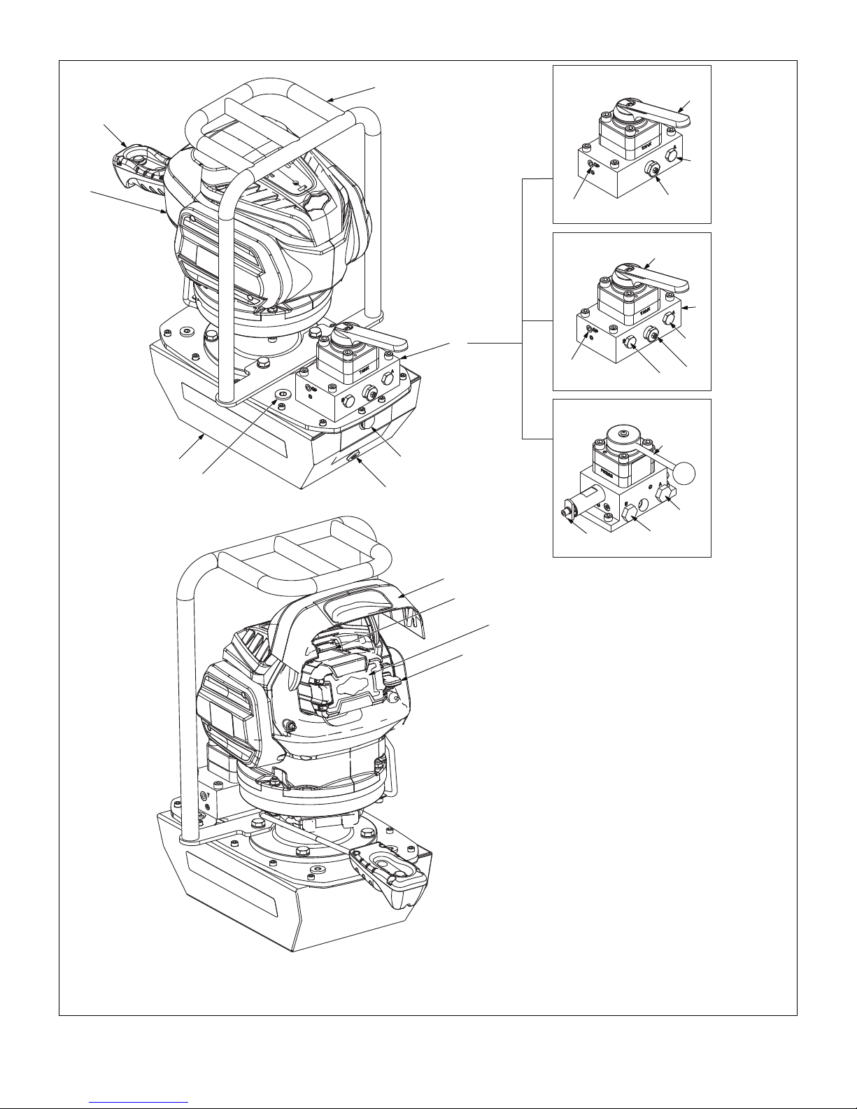
2.0 MAJOR FEATURES AND COMPONENTS
2
ZC-3308J
9
1
10
7
12
11
ZC-3408J
9
15
14
13
11
8
12
ZC-3908J
9
6
3
5
4
16
17
19
18
13
11
14
Key:
1. Remote Pendant
2. Carrying Handle/Roll Bar
3. Hydraulic Reservoir Sight Glass
4. Hydraulic Reservoir Drain Plug
5. Oil Fill Plug
6. Hydraulic Reservoir
7. Pump Motor
8. Directional Control Valve
9. Valve Handle
10. Advance/Retract Port
11. User-adjustable Relief Valve
12. Gauge Port
13. Advance Port
14. Retract Port
15. Auxiliary Tank Return Port
16. Battery Door
17. Battery Release Button
18. Battery
19. Safety Key
Figure 1, Major Features and Components, ZC-Series
5

3.0 PRODUCT DATA
3.1 Specifications
Pump
Model
Number
ZC3308J
ZC3408J
ZC3908J
Pump Model
Number
ZC3308J
ZC3408J
ZC3908J
Control Valve
Model Number and Function
Enerpac VM33
(Advance / Neutral / Retract)
Enerpac VM43
(Advance / Neutral / Retract)
Enerpac VM43LPS
(Advance / Neut. Hold / Retract)
Maximum Hydraulic
Pressure
psi bar
10,000
[+300 / -50]
10,000
[+300 / -50]
10,000
[+300 / -50]
700
[+20.7 / -3.4]
700
[+20.7 / -3.4]
700
[+20.7 / -3.4]
Operating Temp
˚ F ˚ C hp kW dBA
+40 to
+120
+40 to
+120
+40 to
+120
For Use With:
Single-acting
Cylinder
Double-acting
Cylinder
Power Seater
Post-Tensioning
Tools
Hydraulic
Connections
3/8" NPTF
3/8" NPTF
3/8" NPTF
Flow Rate (Refer to Section 3.2)
At
No Load
in³/
min
l/min
At 4,000 psi
[276 bar]
in³/
l/min
min
At 10,000 psi
[700 bar]
in³/
l/min gal l lb kg
min
310 5.0 80 1.3 32 0.52
Range
+4 to
+49
+4 to
+49
+4 to
+49
Reservoir
Size*
Motor Rating
1.4 1.0 75
1.4 1.0 75
1.4 1.0 75
Pump
Weight**
1.75 6.6 65.5 29.7 Enerpac HF
Sound
Pressure
Hydraulic Oil
Type
310 5.0 80 1.3 32 0.52 1.75 6.6 65.5 29.7 Enerpac HF
310 5.0 80 1.3 32 0.52 1.75 6.6 73.4 33.3 Enerpac HF
* Approximate usable capacity of oil reservoir.
** Approximate weight of pump with oil in reservoir and with battery installed.
Weight of battery is approximately 2.4 lb [1.1 kg].
Pump Series Item
Enerpac Briggs & Stratton
Battery Charger, 115V AC, 50/60 Hz Input NA ZC115VC 1760263
ZC-Series
Battery Charger, 230V AC, 50/60 Hz Input EU/AU ZC230VC 1760264
Battery, Lithium Ion, 82V, 4Ah, NA ZC82V4NA 1760265
Battery, Lithium Ion, 82V, 4Ah, EU/AU ZC82V4EUAU 1760515
Batteries and chargers can be purchased from an Enerpac distributor or Briggs & Stratton retailer.
*
3.2 Pressure and Flow Graphs
/min)
3
FLOW/RATE (in
400
350
300
250
200
150
100
FLOW VS. PRESSURE
50
6
5
4
3
FLOW/RATE (il/min)
2
1
FLOW VS. PRESSURE
Model Numbers
FLOW VS. PRESSUREFLOW VS. PRESSURE
*
0
1000 2000 3000 4000 5000 6000 7000 8000 9000 10000 11000
PRESSURE (PSI) PRESSURE (BAR)
NOTE: All product data is subject to change without notice. Graphs in Section 3.2 show typical pump pressure/flow curves.
0
100 200 300 400 500 600 700 800
6
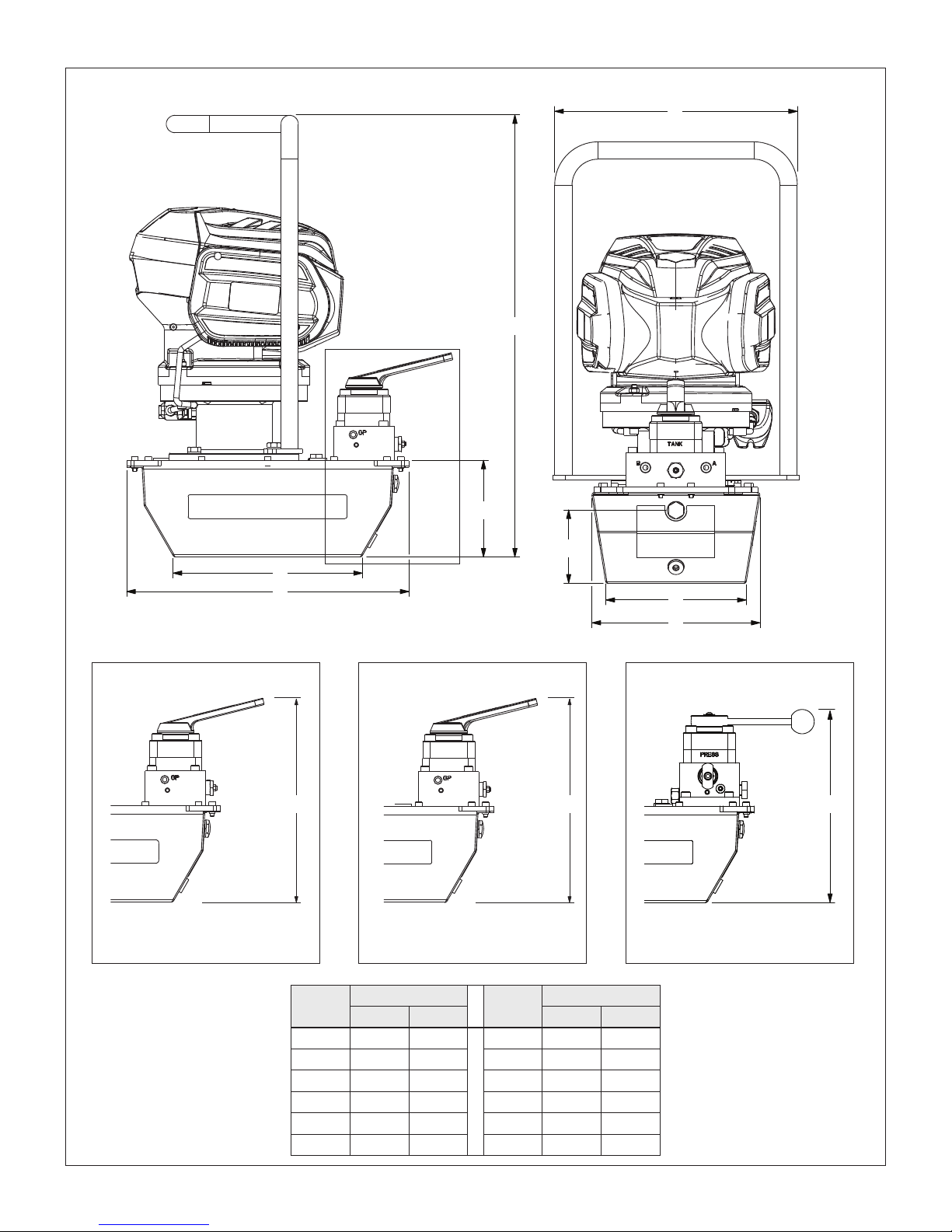
3.3 External Dimensions
B
A
F
E
H
G
D
C
I J K
ZC3308J ZC3408J ZC3908J
Item
A 25.48 647 G 16.28 414
B 14.00 356 H 10.92 277
C 9.69 246 I 11.74 298
D 8.09 205 J 11.74 298
E 4.22 107 K 10.43 265
F 5.66 144
Dimension
in mm in mm
Item
7
Dimension

4.0 PRODUCT DESCRIPTION
NOTICE
NOTICE
4.1 Introduction
The Enerpac ZC-Series combines the high performance of an
electric AC-powered pump with the convenience of a cordless,
battery powered pump. It is an ideal solution for remote locations,
where electrical or pneumatic power sources are not available.
Major features include a brushless DC electric motor, three-stage
pump element and 1.75 gallon [6.6 liter] hydraulic reservoir. Three
dierent control valves are available.
The pump is powered by a rechargeable 82V lithium-ion battery,
manufactured by Briggs & Stratton Corporation. The lithium-ion
battery is capable of providing impressive run times, even under
extreme job site conditions.
4.4 Electromagnetic Compatibility (EMC)
The ZC-Series cordless electric pump has been tested and
certified to conform to CE-EMC emission and immunity
standards.
5.0 IMPORTANT RECEIVING INSTRUCTIONS
Visually inspect all components for shipping damage. Shipping
damage is not covered by warranty. If shipping damage is found,
notify carrier at once. The carrier is responsible for all repair and
replacement costs resulting from damage in shipment.
5.1 Hydraulic Reservoir Breather
A shipping plug is installed in the breather port on the top of the
reservoir. Before using the pump, replace the shipping plug with
the adapter fitting and breather.
Check oil level before operating pump. Refer to
Section 9.1.
1
2
Figure 1, Battery and Charger
4.2 Additional Information - Battery and Charger
• The Briggs & Stratton logo is trademarked and intellectual
property of Briggs & Stratton.
• Portions of this publication are subject to copyright of Briggs
& Stratton Corporation.
4.3 Conformance to National and International Standards
Enerpac declares that the ZC-Series cordless electric pump
has been tested and conforms to applicable standards and is
approved to carry the CE, TUV C and US certification marks. An
EU Declaration of Conformity is enclosed separately.
3
4
Key:
1. Breather
2. Adapter Fitting
Figure 2, Breather and Oil Fill Plug Locations
3. Shipping Plug
4. Oil Fill Plug (SAE #8)
6.0 HYDRAULIC CONNECTIONS
WARNING
tightly bending hoses. If a hose becomes kinked or otherwise
damaged, it must be replaced. Damaged hoses may rupture at
high pressure. Serious personal injury may result.
The pump comes equipped with a 3-way, 3-position control
valve (VM33); 4-way, 3-position control valve (VM43); or a control
valve specifically designed for foundation tensioning (VM43LPS).
is strongly recommended. All hoses and fittings must be rated to
at least 10,000 psi [700 bar].
To ensure proper operation, avoid kinking or
Installation of a pressure gauge in each hydraulic line
8

Figure 3, Hydraulic Connections
NOTICE
NOTICE
1
1. Battery Capacity Indicator Button
2. Indicator Lights
2
As hoses, components and fittings are assembled, apply 1-1⁄2
wraps of PTFE thread sealing tape to all threaded NPT or NPTF
fittings, leaving the first complete thread free of tape as shown in
Figure 3. Use care to prevent pieces of tape from entering the
hydraulic system.
Make hydraulic connections as described in the following steps.
The pumps equipped with the VM43 and VM43LPS control
valves will have ports “A” and “B”. Pumps equipped with the
VM33 control valve will only have port “A”.
1. To prevent the pump from starting, be sure that the battery is
removed from the pump.
2. Remove the plugs from pump ports “A” and “B” (if equipped).
3. As required, install hydraulic fitting(s) at pump port(s). Tighten
fittings(s) finger tight. Then tighten fitting(s) two additional full
turns. Couplings or other hydraulic fittings (user-supplied)
must have 3/8" NPTF threads.
4. Make connections as described for each model:
ZC3308J only:
• Connect the cylinder advance/retract hose to pump port “A”.
ZC3408J and ZC3908J only:
• Connect the hose from the advance side of the cylinder to
pump port “A”.
• Connect the hose from the retract side of the cylinder to
pump port “B”.
5. Pumps equipped with VM43LPS control valve only: some
post-tensioning equipment may require the connection of
a third hydraulic hose. Refer to the manuals provided with
your post-tensioning equipment. Also refer to the Enerpac
VM43LPS instruction sheet.
7.0 BATTERY
7.1 Battery Capacity Indicator
New batteries should be charged before use. Each battery
contains four indicator lights. The battery capacity indicator
lights show the approximate battery capacity level.
Press the battery capacity indicator button to display the lights.
The battery capacity indicator lights will stay lit for two seconds
after the button is pressed. Refer to Figure 4 to determine the
level of charge.
Run time between battery charges is dependent on the
application, pump run time, pressure setting and other factors.
If none of the battery capacity indicator lights illuminate
when the battery capacity indicator is pressed, place the battery
on the charger and charge as needed.
When Battery Capacity Indicator
Button is pressed:
4 Lights ON 80 - 100%
3 Lights ON 60 - 80%
2 Lights ON 40 - 60%
1 Lights ON 25 - 40%
0 Lights ON < 25%
Figure 4, Battery Capacity Indicator
7.2 Battery Installation
1. Ensure that remote pendant switch is in the OFF (O) position.
2. Lift battery door and hold it open.
3. Align ribs on battery and battery bracket. Then, slide the
battery fully into the battery compartment until it stops.
4. Ensure battery release button snaps in place and that
the battery is fully seated and secured before beginning
operation.
5. Close the battery door.
Percent Charge:
(approximate)
1
3
2
4
Key:
1. Battery Door
2. Battery
3. Battery Release Button
4. Safety Key
Figure 5, Battery Installation
9

NOTICE
To ensure compatibility and proper operation, use only
NOTICE
Briggs & Stratton 82V lithium-ion batteries with the pump. Refer
to Section 3.1 for battery model number information.
7.3 Battery Removal
1. Ensure pump motor is switched o.
2. Lift the battery door and hold it open.
3. Press the battery release button located above battery.
4. Slide the battery outwards and remove it from the battery
compartment. Refer to Figure 5.
7.4 Battery Management System
The battery management system monitors and controls battery
operation:
• A low voltage cut-o feature will shut down the battery when
the battery voltage drops to below acceptable limits.
• A high temperature shut down feature will shut down the
battery if its internal temperature rises to above acceptable
limits.
• If the low voltage cut-o or high temperature shut down feature
is activated while the pump is operating, the pump motor will
emit a beeping sound and the pump will stop.
• If the high temperature shut down feature is activated, the
battery must cool down to an acceptable internal temperature
before the pump can be restarted.
7.5 Additional Battery and Charger Information
• The battery is not shipped fully charged. It is recommended
that battery be fully charged before first use to ensure
maximum run time can be achieved.
• For best results, the battery should be charged in a location
with a temperature between 43°F [6.1°C] and 104°F [40°C].
The battery is a lithium-ion device. It will not develop a memory
and may be charged at any time.
• If the battery charger light glows green and blinks when the
battery is placed in the battery charger, this indicates that the
battery is being charged. A solid green light indicates that the
battery is fully charged.
• If the battery charger light glows solid red when the battery is
placed in the battery charger, this indicates that the battery
temperature is above acceptable limits. Leave the battery in
the charger and allow time (up to 30 minutes) for the battery
to cool. The charger should resume charging after the battery
has cooled.
• If the battery has been stored with little to no charge for a long
period of time, the charger will go into recovery mode, which
will take 20 hours to fully charge the battery. This will enhance
the life of the battery. Once the battery is fully charged, the
next charge will return to standard charging.
8.0 OPERATION
8.1 Before Start-up
1. Check all hydraulic fittings and connections to be sure they
are tight and leak free.
2. Install hydraulic reservoir breather. Refer to Section 5.1.
3. Check the hydraulic oil level. Add oil if necessary. Refer to
sections 9.1, 9.2 and 9.3.
4. Install a fully charged battery on the pump. Refer to Section
7.2.
5. Verify safety key is installed.
6. Connect hydraulic hose(s) to pump as described in Section
6.0. Remove air from system before placing pump into
operation. Refer to instructions in Section 8.6.
8.2 Starting the Pump Motor
1. Place control valve lever in the neutral position (“3”). Refer to
sections 8.5.1, 8.5.2 and 8.5.3 for control valve details.
2. To start the pump motor, press the upper half of the remote
pendant rocker switch.
8.3 Stopping the Pump Motor
To stop the pump motor, press the lower half of the remote
pendant rocker switch.
In an emergency, the pump motor can also be stopped
by removing either the safety key or the battery.
1
2
1. On Position
2. O Position
Figure 6, Remote Pendant
8.4 Operating Precautions
WARNING
Failure to observe the following precautions and instructions
could allow load to drop on persons working in the area.
Death or serious personal injury could result.
• Keep persons away from area under load during lifting,
lowering and whenever the control valve lever is moved.
• To prevent the lifted load from dropping, always immediately
support it with jack stands or other mechanical blocking
devices of adequate rated capacity.
• Be certain that blocking is fully in place before moving
the control valve lever from one position to another. An
unsupported load can drop when the control valve is shifted.
• Do not rely on the pump hydraulics to hold lifted loads (pumps
equipped with VM33 or VM43 control valves). The pump is
not designed as a load holding device. The control valve does
NOT contain a safety locking valve in any of its three positions.
• Although in some instances the pump hydraulics may
temporarily hold the load, be aware that the load can drift
downward or drop suddenly at any time without warning if it is
not mechanically supported.
• Pump model ZC3908J is designed exclusively for post-
tensioning applications and should only be used with
compatible post-tensioning equipment. To prevent possible
loss of load and serious personal injury, do not use model
ZC3908J for lifting applications.
8.5 Manual Valve Operation
Each ZC-Series cordless electric pump is equipped with a control
valve. It is operated by a rotary lever located at the front of the
pump. Refer to Figures 7, 8 and 9 for control valve positions.
8.5.1 VM33 Operation
To advance the cylinder:
1. Be sure that control valve is in the neutral position (“3”).
10

1. Advance
2. Retract
3. Neutral
2
3
1
1. Advance
1. Advance
2. Retract
2. Retract
3. Neutral
3. Neutral
2
3
1
Figure 7, VM33 Control Valve Positions
2. Turn pump on by pushing upper half of remote pendant
rocker switch.
3. Move control valve lever to the advance position (“1”). The
cylinder will begin advancing.
The cylinder will continue to advance until the pump is switched
o or the cylinder is fully extended.
To retract the cylinder:
1. Move control valve to the neutral position (“3”).
2. If pump is on, turn pump o by pushing lower half of remote
pendant rocker switch.
3. Move control valve lever to the retract position. The cylinder
will begin retracting.
The cylinder will continue to retract until the control valve lever
is placed in the neutral position (“3”) or until the cylinder is fully
retracted. Additional hydraulic devices may be required to control
the rate of cylinder retraction.
The VM33 control valve blocks hydraulic flow in the cylinder hose
when the lever is moved to the neutral position (“3”). However, the
valve is not designed for holding loads. After lifting is completed,
the load must be mechanically supported. Refer to warning
statements and related information in Section 8.4.
8.5.2 VM43 Operation
To advance the cylinder:
1. Be sure that the control valve lever is in the neutral (“3”)
position.
2. Turn pump on by pushing upper half of remote pendant
rocker switch.
3. Move control valve lever to the advance (“1”) position. The
cylinder will begin advancing.
The cylinder will continue to advance until the control valve is
moved to the neutral position (“3”), the pump motor is switched
o or the cylinder s fully extended.
To retract the cylinder:
1. Be sure that the control valve lever is in the neutral (“3”)
position.
2. Turn pump on by pushing upper half of remote pendant
rocker switch. Pump must be on to retract cylinder.
3. Move control valve lever to the retract (“2”) position. The
cylinder will begin to retract.
Figure 8, VM43 Control Valve Positions
The cylinder will continue to retract until the control valve lever
is moved to the neutral position (“3”) or until the cylinder is fully
retracted. Additional hydraulic devices may be required to control
the rate of cylinder retraction.
The VM43 control valve blocks hydraulic flow in both cylinder
hoses when the lever is moved to the neutral position (“3”).
However, the valve is not designed for holding loads. After lifting
is completed, the load must be mechanically supported. Refer to
warning statements and related information in Section 8.4.
8.5.3 VM43LPS Operation (post-tensioning applications only)
For detailed operating instructions, refer to the separate
instruction sheet provided with the VM43LPS control valve. Also
refer to the operation manuals supplied with the post-tensioning
equipment being used.
2
1. Advance/Stressing
1
2. Retract/Seating
3. Neutral/Hold
3
Figure 9, VM43LPS Control Valve Positions
8.6 Air Removal
When hydraulic components are connected for the first time,
air will be trapped in the components. To ensure smooth, safe
operation, run the cylinder through several complete advanceretract cycles before placing the pump into service. Do this with
no load on the cylinder and with the pump positioned higher than
the cylinder.
When the cylinder advances and retracts smoothly and without
hesitation, the air has been vented from the system.
11

NOTICE
Trapped air purged from system components will return
NOTICE
NOTICE
NOTICE
NOTICE
to reservoir. Oil level may drop. Add additional oil (if required) to
reservoir after purging air. Refer to Section 9.3.
8.7 Disconnecting Hydraulic Hoses
Disconnect hydraulic hoses after use as described in the
following steps:
1. Fully retract the cylinder or tool. Be sure that the load is
completely removed from the device.
2. Move the control valve lever back and forth between the
advance (“1”) and retract (“2”) positions several times to
relieve any trapped pressure.
3. If pressure gauges have been installed, verify that the gauges
indicate zero (0) psi/bar.
4. Disconnect hydraulic hoses from pump.
5. To prevent contamination, cap or plug all open hydraulic
couplings and ports.
8.8 Transporting the Pump
Always transport the pump using the built-in carrying handle.
Never attempt to transport or reposition the pump by dragging
it by the hoses. Damage to the pump and/or hoses may result.
9.0 MAINTENANCE
9.1 Check Oil Level
1. Be sure hydraulic cylinder or other tool is fully retracted.
2. Rotate the control valve lever back and forth several times
between the advance and retract positions (“1” and “2”) to
remove any trapped pressure.
3. Remove the battery from the pump. Refer to Section 7.2.
4. Place the pump on a level surface.
5. Visually check the oil level by looking through the hydraulic
reservoir sight glass. Reservoir is FULL when oil level is
about halfway between the top and bottom of the sight
glass. Refer to Figure 10.
If oil level is low:
Add oil as described in Section 9.3. Refer to Section 9.2 for
oil requirements.
9.2 Hydraulic Oil Information
Use only Enerpac HF hydraulic oil when adding additional oil
or when performing an oil change. Enerpac HF hydraulic oil is
available from Enerpac distributors and Enerpac authorized
service centers.
Use only Enerpac HF hydraulic oil. Use of other oils
may result in damage to pump components. Such damage is not
covered under the Enerpac product warranty.
9.3 Adding Oil
1. Be sure hydraulic cylinder or tool is fully retracted.
2. Rotate the control valve lever back and forth several times
between the advance and retract positions (“1” and “2”) to
remove any trapped pressure.
3. Disconnect hydraulic hoses.
4. Remove the battery from the pump. Refer to Section 7.3.
5. Place the pump on a level work surface.
6. Remove SAE #10 plug from cover plate. Refer to Figure 2.
7. Slowly fill the reservoir with new oil until level is about halfway
between the top and bottom of the hydraulic reservoir sight
glass. Refer to Section 9.2 for oil requirements.
Do NOT overfill. Be certain that all hydraulic cylinders
are fully retracted before adding any oil. Over filling hydraulic
reservoir may cause damage to the pump.
9.4 Oil Change
Change the hydraulic oil in the pump reservoir at least once
a year, or whenever it is suspected that the oil has become
contaminated.
To properly drain and refill the reservoir, change the oil as
described in the following steps. Refer to Figure 10.
1. Be sure hydraulic cylinder or tool is fully retracted.
2. With the pump o, rotate the control valve lever back
and forth several times between the advance and retract
positions (“1” and “2”) to remove any trapped pressure.
3. Remove the battery from the pump.
4. Disconnect hydraulic hoses from pump.
1
Key:
1. Hydraulic Reservoir Sight Glass
2. Drain Plug
Figure 10, Hydraulic Reservoir
ZC-Series pumps are equipped with a 1.75 gallon [6.6
liter] hydraulic reservoir. Be sure the pan or container is large
enough to hold all the drained oil.
5. Place a suitable pan or container of appropriate capacity
under the hydraulic reservoir drain plug. Refer to Figure 10.
6. Remove hydraulic reservoir drain plug.
7. Allow used oil to drain completely from reservoir.
8. Clean hydraulic reservoir drain plug and remove any metal
shavings (plug is magnetic).
9. Reinstall hydraulic reservoir drain plug.
Dispose of used oil in accordance with all applicable
laws and regulations.
10. Refill hydraulic reservoir with new oil. Refer to Section 9.3.
2
Full
12

10.0 PRESSURE RELIEF VALVE ADJUSTMENT
NOTICE
NOTICE
NOTICE
WARNING
Never adjust the pressure relief valve setting above 10,000 psi
[700 bar]. Be certain that the pressure setting does not exceed
the maximum rated pressure of the cylinder (or tool) being
used. Failure to observe these precautions may result in failure
of cylinder or tool and related components. Death or serious
personal injury could occur.
10.1 VM33 and VM43 Only
1. Install a 0-15,000 psi [0-1035 bar] gauge in the “A” port. Refer
to Figure 11.
2. VM43 Only: Install a 3/8" pipe plug in the “B” port and torque
to 25 ft-lbs [33 Nm].
3. Loosen the relief valve locknut to permit adjustment of set
screw.
4. Rotate the control valve handle to the neutral position (“3”).
Refer to Figures 7 and 8 for valve handle positions.
5. Start the pump and allow the oil to warm.
6. Rotate the control valve handle to the advance position (“1”).
Allow pressure to build.
7. To increase pressure: SLOWLY turn the relief valve set screw
clockwise until pressure increases to the desired setting.
An internal check valve in the manifold will prevent the
pressure from dropping when the set screw is turned counterclockwise. To lower the pressure setting, follow steps 8a through
8e.
8. To decrease pressure:
a. Be sure the pump is running.
b. Rotate the control valve handle to the neutral position
(“3”) to relieve pressure on the “A” port.
c. Turn the relief valve set screw counter-clockwise one
turn.
d. Rotate the control valve handle to the advance position
(“1”).
e. SLOWLY turn the relief valve set screw clockwise until “A”
port pressure increases to the desired setting.
9. When the desired pressure setting is reached, lock the set
screw with the locknut. DO NOT overtighten.
10. Before turning o pump, rotate the control valve handle
momentarily to the retract position (“2”) to relieve pressure at
the “A” port. Then, rotate the handle to the neutral position
(“3”). Check that gauge indicates zero (0) psi/bar.
11. Shut o the pump.
10.2 VM43LPS Only
1. Install a 0-15,000 psi [0-1035 bar] gauge in the stressing
pressure gauge “A” port. Refer to Figure 12.
2. Install a 3/8" pipe plug in the seating port “B” port and torque
to 25 ft-lbs [33 Nm].
3. Loosen the relief valve locknut to permit adjustment of set
screw.
4. Rotate the control valve handle to the neutral/hold position.
Refer to Figure 9 for valve handle positions.
5. Start the pump and allow the oil to warm.
6. Rotate the control valve handle to the advance position (“1”).
Allow pressure to build.
Use a 5mm Allen wrench to adjust the relief valve set
screw.
7. To increase pressure: With the pump running, SLOWLY turn
the relief valve set screw clockwise until stressing “A” port
pressure increases to the desired setting.
A pilot-operated check valve in the locking valve block
will prevent the pressure from dropping when the set screw is
turned counter-clockwise. To lower the pressure setting, follow the
procedure in steps 8a through 8e.
8. To decrease pressure:
a. Be sure the pump is running.
b. Rotate the control valve handle to the retract/seating
position momentarily. This will activate the pilotoperated check valve and relieve pressure at the
stressing “A” port. Then, rotate the handle to the neutral/
hold position.
c. Turn the relief valve set screw counter-clockwise one
turn.
d. Rotate the control valve handle to the advance/stressing
position.
e. SLOWLY turn the relief valve set screw clockwise until
stressing port “A” pressure increases to the desired
setting.
9. When the desired pressure setting is reached, lock the set
screw with the locknut. DO NOT overtighten.
10. Before turning o pump, rotate the control valve handle
momentarily to the retract position to relieve pressure at the
stressing “A” port. Then, rotate the handle to the neutral/
hold position. Check that stressing pressure gauge (“A” port)
indicates zero (0) psi/bar.
11. Shut o the pump.
Relief Valve Body (DO NOT TURN)
“B” Port
(VM43 Only)
Figure 11, Relief Valve - VM33 and VM43
Locknut
Set screw
AB
“A” Port
Relief Valve Body
(DO NOT TURN)
Locknut
Set Screw
13
“A” Port
“B” Port
Figure 12, Relief Valve - VM43LPS

11.0 TROUBLESHOOTING
The information in the Troubleshooting Guide is intended as an
aid to help diagnose and correct various possible problems that
may occur.
For repair service, contact your nearest Enerpac Authorized
Service Center. Only an Enerpac Authorized Service Center
should be permitted to service the pump and its components.
Failure to observe and comply with the following precautions
could result in death or serious personal injury. Property
damage could also occur.
• Never tighten or loosen hydraulic fittings while the pump
hydraulic system or connected components are pressurized.
Escaping oil under pressure can penetrate the skin, causing
serious personal injury.
• Keep hands, fingers and other body parts clear of pinch
points and moving parts when observing operation during
troubleshooting.
• To prevent accidental start-up of pump during servicing,
always remove battery from pump before performing any
maintenance or repair procedures.
WARNING
TROUBLESHOOTING GUIDE
Symptom Possible Cause Solution
1. Pump will not start. a. Battery is not installed. Install battery.
b. Safety key is not inserted. Insert safety key.
c. Battery is discharged. Charge battery.
d. Electrical contacts are dirty or
corroded.
2. Pump clicks when
remote pendant switch
is on, but does not
start.
3. Low fluid output. a. Pump needs priming. To prime the pump, be sure that the pump reservoir is filled
4. Pump does not build
pressure.
5. Noisy and/or vibrating
pump operation.
6. Battery charge is
reduced after more than
one month of use.
a. Battery is discharged. Charge battery.
b. Battery is damaged or not
functioning.
c. Electrical contacts are dirty or
corroded.
d. Pump is jammed due to
obstruction. Possible internal
damage to pump.
b. Bypass valve malfunction. Contact Enerpac Authorized Service Center.
c. Oil intake screen is clogged with
debris.
d. Internal damage to pump. Contact Enerpac Authorized Service Center.
Pressure relief valve is set too
low.
a. Pump element piston is sticking. Contact Enerpac Authorized Service Center.
b. Motor is damaged. Contact Enerpac Authorized Service Center.
The battery has automatically
performed self-maintenance to
extend its life.
Clean contacts on the battery, pump and charger.
Replace battery.
Clean contacts on the battery, pump and charger.
Contact Enerpac Authorized Service Center.
with oil. Then, run the pump with the control valve in the
neutral position (“3”) while gently rocking the pump from
side-to-side.
Contact Enerpac Authorized Service Center.
Adjust pressure relief valve pressure setting. Refer to
Section 10.
Fully recharge battery before use.
(continued on next page)
14

Symptom Possible Cause Solution
7. Cylinder will not
advance or retract.
8. Pump slows down and
stops.
9. Cylinder advances and
retracts erratically.
TROUBLESHOOTING GUIDE (continued)
a. Valve handle in wrong position. Move valve handle to position “1” to advance.
Move valve handle to position “2” to retract.
b. Oil level low. Add oil until reservoir is full.
c. Pump needs priming. To prime the pump, be sure that the pump reservoir is filled
with oil. Then, run the pump with the control valve in the
neutral position (“3”) while gently rocking the pump from
side-to-side.
d. Oil intake screens are clogged
Contact Enerpac Authorized Service Center.
with debris.
Battery is discharged. Charge battery.
a. Air is in the system. Advance and retract the cylinder until operation is smooth.
b. External hydraulic leak. Tighten connections. Replace damaged components.
c. Internal leakage in valve. Contact Enerpac Authorized Service Center.
d. Internal damage to valve. Contact Enerpac Authorized Service Center.
e. Internal damage to pump. Contact Enerpac Authorized Service Center.
15

POWERFUL SOLUTIONS. GLOBAL FORCE.
http://www.enerapac.com

41
L1057 Rev. C 08/12 www.enerpac.com

3 - In Use
42
B
A
2
3
1

B
43
A

A
PT
A
PT
A
PT
A
PT
A
PT
A
PT
VM33
VM33L
P
T
A
"GA"
"GP"
"GP"
T
P
T
A
"GP"
"GP"
"GA"
T
44

4
APTB
PT
A B
AB
APTB
APTB
PT
A B
VM43
VM43
P
T
A
B
"GA"
"GB"
"GP"
"GP"
T
P
T
"GP"
"GP"
T
A
B
"GA"
"GB"
45
PT

Australia and New Zealand
Actuant Australia Ltd.
Block V Unit 3
Regents Park Estate
391 Park Road
Regents Park NSW 2143
(P.O. Box 261) Australia
T +61 (0)2 9743 8988
F +61 (0)2 9743 8648
sales-au@enerpac.com
Brazil
Power Packer do Brasil Ltda.
Rua dos Inocentes, 587
04764-050 - Sao Paulo (SP)
T +55 11 5687 2211
F +55 11 5686 5583
Toll Free: 0800 891 5770
vendasbrasil@enerpac.com
Canada
Actuant Canada Corporation
6615 Ordan Drive, Unit 14-15
Mississauga, Ontario L5T 1X2
T +1 905 564 5749
F +1 905 564 0305
Toll Free:
T +1 800 268 4987
F +1 800 461 2456
customer.service@actuant.com
China
Actuant (China) Industries Co. Ltd.
No. 6 Nanjing East Road,
Taicang Economic Dep Zone
Jiangsu, China
T +86 0512 5328 7500
F +86 0512 5335 9690
Toll Free: +86 400 885 0369
sales-cn@enerpac.com
France, Switzerland, North Africa
and French speaking African
countries
ENERPAC
Une division d’ACTUANT France S.A.
ZA de Courtaboeuf
32, avenue de la Baltique
91140 VILLEBON /YVETTE
France
T +33 1 60 13 68 68
F +33 1 69 20 37 50
sales-fr@enerpac.com
Germany and Austria
ENERPAC GmbH
P.O. Box 300113
D-40401 Düsseldorf
Willstätterstrasse 13
D-40549 Düsseldorf, Germany
T +49 211 471 490
F +49 211 471 49 28
sales-de@enerpac.com
India
ENERPAC Hydraulics Pvt. Ltd.
No. 1A, Peenya Industrial Area
IInd Phase, Bangalore, 560 058, India
T +91 80 40 792 777
F +91 80 40 792 792
sales-in@enerpac.com
Italy
ENERPAC S.p.A.
Via Canova 4
20094 Corsico (Milano)
T +39 02 4861 111
F +39 02 4860 1288
sales-it@enerpac.com
Japan
Applied Power Japan LTD KK
Besshocho 85-7
Kita-ku, Saitama-shi 331-0821, Japan
T +81 48 662 4911
F +81 48 662 4955
sales-jp@enerpac.com
Middle East, Egypt and Libya
ENERPAC Middle East FZE
Oce 423, LOB 15
P.O. Box 18004, Jebel Ali, Dubai
United Arab Emirates
T +971 (0)4 8872686
F +971 (0)4 8872687
sales-ua@enerpac.com
Russia
Rep. oce Enerpac
Russian Federation
Admirala Makarova Street 8
125212 Moscow, Russia
T +7 495 98090 91
F +7 495 98090 92
sales-ru@enerpac.com
Singapore
Actuant Asia Pte Ltd.
83 Joo Koon Circle
Singapore 629109
T +65 68 63 0611
F +65 64 84 5669
Toll Free: +1800 363 7722
sales-sg@enerpac.com
South Korea
Actuant Korea Ltd.
3Ba 717, Shihwa Industrial Complex
Jungwang-Dong, Shihung-Shi,
Kyunggi-Do
Republic of Korea 429-450
T +82 31 434 4506
F +82 31 434 4507
sales-kr@enerpac.com
Spain and Portugal
ENERPAC SPAIN, S.L.
Avda. Los Frailes, 40 – Nave C & D
Pol. Ind. Los Frailes
28814 Daganzo de Arriba
(Madrid) Spain
T +34 91 884 86 06
F +34 91 884 86 11
sales-es@enerpac.com
Sweden, Denmark, Norway, Finland
and Iceland
Enerpac Scandinavia AB
Fabriksgatan 7
412 50 Gothenburg
Sweden
T +46 (0) 31 799 0281
F +46 (0) 31 799 0010
scandinavianinquiries@enerpac.com
The Netherlands, Belgium,
Luxembourg,
Central and Eastern Europe,
Baltic States, Greece, Turkey
and CIS countries
ENERPAC B.V.
Galvanistraat 115
6716 AE Ede
P.O. Box 8097
6710 AB Ede
The Netherlands
T +31 318 535 911
F +31 318 535 848
sales-nl@enerpac.com
Enerpac Integrated Solutions B.V.
Opaalstraat 44
7554 TS Hengelo
P. O. B o x 42 1
7550 AK Hengelo
The Netherlands
T +31 74 242 20 45
F +31 74 243 03 38
integratedsolutions@enerpac.com
South Africa and other English
speaking African countries
Enerpac Africa Pty Ltd.
No. 5 Bauhinia Avenue
Cambridge Oce Park
Block E
Highveld Techno Park
Centurion 0157
South Africa
T: +27 12 940 0656
United Kingdom and Ireland
ENERPAC Ltd.,
Bentley Road South
Darlaston, West Midlands
WS10 8LQ
England
T +44 (0)121 50 50 787
F +44 (0)121 50 50 799
sales-uk@enerpac.com
USA, Latin America and Caribbean
ENERPAC
P.O. Box 3241
Milwaukee WI 53201 USA
T +1 262 293 1600
F +1 262 293 7036
User inquiries:
T +1 800 433 2766
Distributor inquiries/orders:
T +1 800 558 0530
F +1 800 628 0490
Technical inquiries:
techservices@enerpac.com
sales-us@enerpac.com
Enerpac Worldwide Locations e-mail: info@enerpac.com internet: www.enerpac.com
All Enerpac products are guaranteed
against defects in workmanship and
materials for as long as you own them.
For the location of your nearest authorized
Enerpac Service Center, visit us at
www.enerpac.com
101711
 Loading...