

Enerpac Z-Class, Z H Series, Z L Series, Z 2 S Series, Z 1 0 Series Instruction Sheet
...
Instruction Sheet
POWERFUL SOLUTIONS. GLOBAL FORCE.
LCD Control Panel Operation - Firmware 7.x
L2940 Rev. A 07/09
1.0 SAFETY ISSUES
Read all instructions, warnings and cautions
carefully. Follow all safety precautions to avoid
personal injury or property damage during system
operation. Enerpac cannot be responsible for damage or injury
resulting from unsafe product use, lack of maintenance or
incorrect product and/or system operation. Contact Enerpac
when in doubt as to the safety precautions and operations. If you
have never been trained on high-pressure hydraulic safety,
consult your distribution or service center for a free Enerpac
Hydraulic safety course.
Failure to comply with the following cautions and warnings could
cause equipment damage and personal injury.
A CAUTION is used to indicate correct operating or maintenance
procedures and practices to prevent damage to, or destruction
of equipment or other property.
A WARNING indicates a potential danger that requires correct
procedures or practices to avoid personal injury.
A DANGER is only used when your action or lack of action may
cause serious injury or even death.
WARNING: Wear proper personal protective gear when
operating hydraulic equipment.
WARNING: Stay clear of loads supported by
hydraulics. A cylinder, when used as a load lifting device,
should never be used as a load holding device. After the
load has been raised or lowered, it must always be blocked
mechanically.
WARNING: USE ONLY RIGID PIECES TO HOLD
LOADS. Carefully select steel or wood blocks that are
capable of supporting the load. Never use a hydraulic
cylinder as a shim or spacer in any lifting or pressing application.
DANGER: To avoid personal injury keep hands
and feet away from cylinder and workpiece
during operation.
WARNING: The system operating pressure must not
exceed the pressure rating of the lowest rated component
in the system. Install pressure gauges in the system to
monitor operating pressure. It is your window to what is happening
in the system.
CAUTION: Avoid damaging hydraulic hose. Avoid
sharp bends and kinks when routing hydraulic hoses.
Using a bent or kinked hose will cause severe back-pressure.
Sharp bends and kinks will internally damage the hose leading to
premature hose failure.
Do not drop heavy objects on hose. A sharp impact
may cause internal damage to hose wire strands.
Applying pressure to a damaged hose may cause it
to rupture.
IMPORTANT: Do not lift hydraulic equipment by the
hoses or swivel couplers. Use the carrying handle or
other means of safe transport.
Z-Class Electric Pumps
CAUTION: Keep hydraulic equipment away from
fl ames and heat. Excessive heat will soften packings
and seals, resulting in fl uid leaks. Heat also weakens
hose materials and packings. For optimum performance do not
expose equipment to temperatures of 65°C [150°F] or higher.
Protect hoses and cylinders from weld spatter.
DANGER: Do not handle pressurized hoses. Escaping
oil under pressure can penetrate the skin, causing
serious injury. If oil is injected under the skin, see a
doctor immediately.
WARNING: Only use hydraulic cylinders in a coupled
system. Never use a cylinder with unconnected couplers. If
the cylinder becomes extremely overloaded, components
can fail catastrophically causing severe personal injury.
WARNING: BE SURE SETUP IS STABLE BEFORE
LIFTING LOAD. Cylinders should be placed on a fl at
surface that can support the load. Where applicable, use
a cylinder base for added stability. Do not weld or otherwise
modify the cylinder to attach a base or other support.
Avoid situations where loads are not directly centered
on the cylinder plunger. Off-center loads produce
considerable strain on cylinders and plungers. In
addition, the load may slip or fall, causing potentially dangerous
results.
IMPORTANT: Hydraulic equipment must only be serviced
by a qualifi ed hydraulic technician. For repair service,
contact the Authorized ENERPAC Service Center in your
area. To protect your warranty, use only ENERPAC oil.
WARNING: Immediately replace worn or damaged parts
with genuine ENERPAC parts. Standard grade parts will
break causing personal injury and property damage.
ENERPAC parts are designed to fi t properly and withstand high
loads.
WARNING: Do not use electric pumps in an explosive
atmosphere. Adhere to all local and national electrical
codes. A qualifi ed electrician must do installation and
modifi cation.
WARNING: Keep hands clear of moving parts and
pressurized hoses.
One
Button
Three
Button
WARNING: These pumps have internal factory adjusted
relief valves, which must not be repaired or adjusted
except by an Authorized Enerpac Service Center.
WARNING: To prevent damage to pump electric motor,
check specifi cations. Use of incorrect power source
will damage the motor.
2.0 STARTUP
IMPORTANT:
• Pumps with optional pressure transducer: Review Automode
information in sections 4.0 and 5.0 before starting pump.
• Pumps with optional pressure switch: Review section 6.7 G
before starting pump.
1. Check the oil level of pump and add oil if necessary. Refer to
pump instruction sheet.
2. Make sure the shipping plug has been removed and the
breather cap is installed. Refer to pump instruction sheet.
3. Place manual control valve (all models NOT equipped with
electric valve) in the Neutral position.
4. Connect unit to power. Wait about 2 seconds - until “READY” is
displayed - before pressing any button on shroud or pendant.
Refer to section 6.2 for additional boot sequence information
Note: During the boot sequence, the microprocessor will identify
operation of any button as a potential malfunction and will
prevent the motor from starting. Reset by disconnecting power
for 10 seconds.
5. Adjust relief valve as described in section 5.0.
6. For Motor On/Off and valve operation: refer to sections 3.1
through 3.4 for instructions applicable to your specifi c valve
and pendant confi guration. For models equipped with a foot
switch, refer to section 3.5.
3.0 VALVE, PENDANT AND FOOT SWITCH
OPERATION
2
2
3.1 Manual Valve
Operation
VM32 (See Fig. 1)
1. Advance
2. Retract
Shroud On/Off=
Toggle Motor On or Off
Tank
Tank
Pressure
Pressure
Figure 1
Figure 1
1
1
® ®
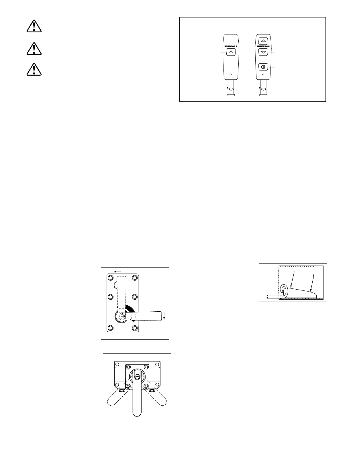
Up Arrow/
ON/OFF
Up Arrow
Down Arrow
ON / OFF
Figure 3, Pendant Button Variations
3.3 VE33, VE43 and VEW43P Electric Valves with
3-Button Pendant Operation
Also known as a Remote Pump - oil fl ow and motor are both
controlled by the pendant (see Fig. 3).
1. Up Arrow = Momentary Advance
2. Down Arrow = Momentary Retract
3. On/Off = Toggle Motor On or Off
Shroud On/Off = Toggle motor On or Off
3.4 VE32D Electric Valve with 1-Button Pendant
Operation
Also known as a Dump Pump - Oil fl ow and motor are both
controlled by the pendant. The pump will run and the cylinder
will advance when the pendant button is pressed. Releasing the
button will stop the pump and the cylinder will retract automatically
(see Fig. 3).
1. Up Arrow = Momentary Advance
Shroud On/Off = Toggle Motor Off Only
3.5 Valves with foot switch (See Fig. 4)
A. All valves except VE32D
1. Momentary advance or motor
on
2. Momentary retract (if
applicable)
Shroud On/Off = Toggle Motor
On or Off
Figure 4Figure 4
B. VE32D valves
1. Not used
2. Momentary advance
Shroud On/Off = Toggle Motor Off
3.2 VM33, VM33L, VM43,
and VM43L
(See Fig. 2)
1. Advance
2. Retract
3. Neutral
Shroud On/Off =
Toggle Motor On or Off
3 - In Use
3 - In Use
A
B
B
2
2
Figure 2
Figure 2
A
1
1
3
3
2

4.0 AUTOMATIC PUMP OPERATION
(Pumps equipped with pressure transducer option)
Pumps equipped with the pressure transducer option have the
ability to react automatically at a user-defi ned upper and lower
pressure value. This feature is called “Automode”.
Automode can be turned on or off as desired, at the LCD control
panel.
Automode controlled operation of the motor and electric valve
(if equipped) will vary, depending on pump type . The pump type
appears briefl y on the LCD when power is connected to the
pump.
Refer to Table 1 for a list of the pump types covered in this
manual. Refer to Table 4, Pump Model Matrix, (located near the
end of this document) for a description of the specifi c operational
characteristics for each pump type.
Table 1 - Pump Types
Number Pump/Valve Description
1 . . . . . . . . . . . . . . . . . . . Manual w/LCD (manual valve)
2 . . . . . . . . . . . . . . . . . . . Advance/Hold /Retract (electric valve)
3 . . . . . . . . . . . . . . . . . . . Dump (electric valve)
6 . . . . . . . . . . . . . . . . . . . Remote 3 or 4-Way (electric valve)
8 . . . . . . . . . . . . . . . . . . . Jog (manual valve)
10 . . . . . . . . . . . . . . . . . . 3 or 4-Way Manual Momentary
. . . . . . . . . . . . . . . . . . . Local Mode Default (electric valve)
4.1 Overview of Automode Operation
Refer to paragraphs A through D of this section for an overview
of Automode operation and features.
4.1 A. If Automode is ON, and LO PRESS setting is
greater than zero (Pump types 1, 2, 6, 8 and 10)
I. Before the HI PRESS value is reached:
• The pendant buttons and shroud On/Off button will function as
described in sections 3.1 – 3.4.
• The text “AUTO” will be shown on the LCD, reminding the
operator that Automode is active, and that the pump will take
control when system pressure rises to the HI PRESS value.
II. After the HI PRESS value is reached:
• Pump types 1 and 8: The pump motor will stop.
• Pump type 2: The pump motor will stop and the electric valve
will shift.
• Pump types 6 and 10: The pump motor will keep running and
the electric valve will shift.
• The LCD text will change from “AUTO” to “AUTO ON” and the
LCD backlight will begin fl ashing on and off. This indicates that
Automode is now controlling pump operation automatically as
required to maintain the set pressure range.
WARNING: All personnel must be aware that motor can
start and/or valve can shift at any time when backlight
is fl ashing and “AUTO ON” is displayed on the LCD.
WARNING: Always set Automode to OFF and
disconnect electrical power to pump before
disconnecting hoses or performing any
adjustments, maintenance or repairs.
III. When system pressure drops to the LO PRESS value:
• Pump types 1 and 8: The pump motor will restart.
• Pump types 6 and 10: The electric valve will shift.
• Pump type 2: The pump motor will restart and the electric
valve will shift.
4.1 B. If Automode is ON, and LO PRESS setting is set
to zero (0) or OFF (Pump types 1, 2, 3, 6, 8 and 10)
Note: On pump type 3 only, the LO PRESS function is not used,
and is automatically set to zero (0) by the microcontroller.
I. Before the HI PRESS value is reached:
• The pendant buttons and shroud On/Off button will function
as described in sections 3.1 – 3.4.
• The text “AUTO” will be shown on the LCD, reminding the
operator that Automode is active, and that the pump will take
control when system pressure rises to the HI PRESS value.
II. After the HI PRESS value is reached:
• Pump types 1, 2, 3 and 8: The pump motor will stop and the
electric valve will shift.
• Pump types 6 and 10: The pump motor will keep running and
the electric valve will shift.
• The LCD will continue to display “AUTO” and the LCD backlight
will remain turned on (will not fl ash on and off).
4.1 C. If Automode is OFF
(Pump types 1, 2, 3, 6, 8 and 10)
• The LCD will display “READY” in the text area.
• The LCD will indicate system pressure as a simple pressure
gauge, no additional actions will be performed regardless of
previously set HI PRESS and LO PRESS values.
4.1 D. Additional Information
• Pressing and releasing any button on the pendant (if equipped)
or shroud will stop the automatic cycle. Pressing the pendant
Down-Arrow (if applicable) will also retract the cylinder. Pressing
the motor On/Off button will also de-energize the motor if it is
running.
• To restart the automatic cycle, press and release the pendant
Up-Arrow button (if applicable) or the motor On/Off button (See
section 3.1– 3.4).
• Refer to sections 6.1 through 6.5 later in this document for
and detailed LCD operating instructions and descriptions of the
Automode LCD screens.
3
5.0 RELIEF VALVE ADJUSTMENT
Z-Class pumps are equipped with one user adjustable relief valve
(see Figure 5.)
IMPORTANT: To ensure proper pump operation:
• On pumps equipped with the optional pressure transducer, the
relief valve must be set at least 200 psi [13.7 bar] above the HI
PRESS value.
• On pumps equipped with the optional pressure switch (see
section 7.0), the relief valve must be set at least 200 psi [13.7 bar]
above the pressure switch setting.
To adjust the relief valve pressure setting:
1. Install a gauge on the pump.
2. If the pump is equipped with the optional pressure transducer,
verify AUTOMODE is off (See section 6.5C for additional
details).
3. Start the pump to allow the oil to warm.
4. Loosen the set screw locking nut.
5. Shift the control valve and build pressure in the system. Using
an Allen wrench, turn the set screw counter-clockwise to
decrease pressure and clockwise to increase pressure.
Note: To obtain an accurate setting, decrease the pressure
to a point below the fi nal setting and then slowly increase the
pressure until it reaches the fi nal setting.
6. Tighten the locking nut when the desired pressure is set.
7. Shift the control valve to the neutral position, allowing the
system pressure to return to 0 psi.
8. Recheck the fi nal pressure setting by shifting the control valve
and pressurizing the system.
Relief valve body
(DO NOT TURN)
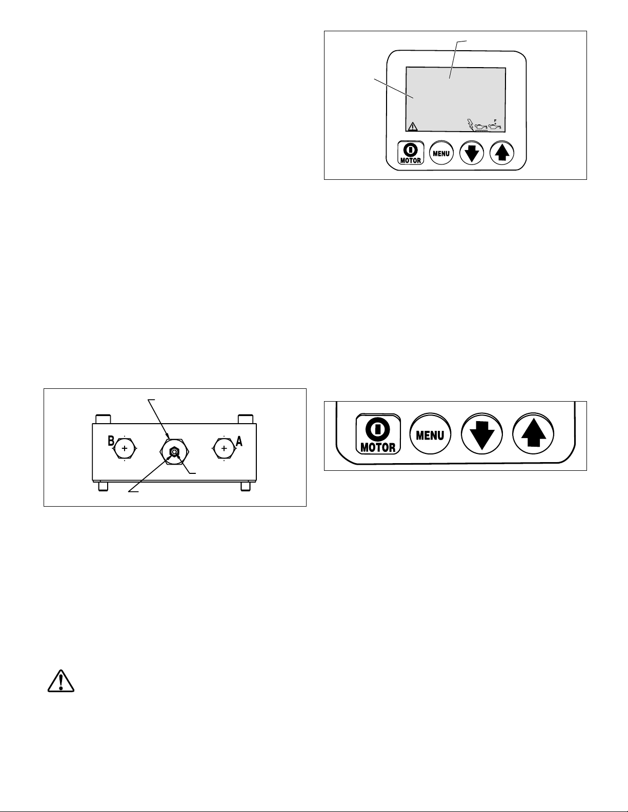
Text Display
Numeric
Display
6.2 Boot Sequence
When the pump is connected to electrical power, the LCD screen
will show: “FIRMWARE 7.x” for 1 second, then “Model XX” for
0.5 seconds. Following these messages, “Motor UN”, “Motor
1P” or “Motor 3P” will appear for 0.5 seconds. This information
may be useful if the pump ever requires servicing or repairs.
Additional information may appear, depending on pump model
and installed accessories.
The boot sequence is successfully completed when the text
display on the LCD screen shows “READY” (sequence takes
approximately 3 seconds). On pumps equipped with the pressure
transducer option, the current system pressure (typically “0” if
motor is not running) will also appear on the numeric display.
SET
00000000
0000.0
HOURS CYCLES
LOW MOTOR
VOLTAGE OVERLOAD
Figure 6, LCD Control Panel
PSI MPa
BAR
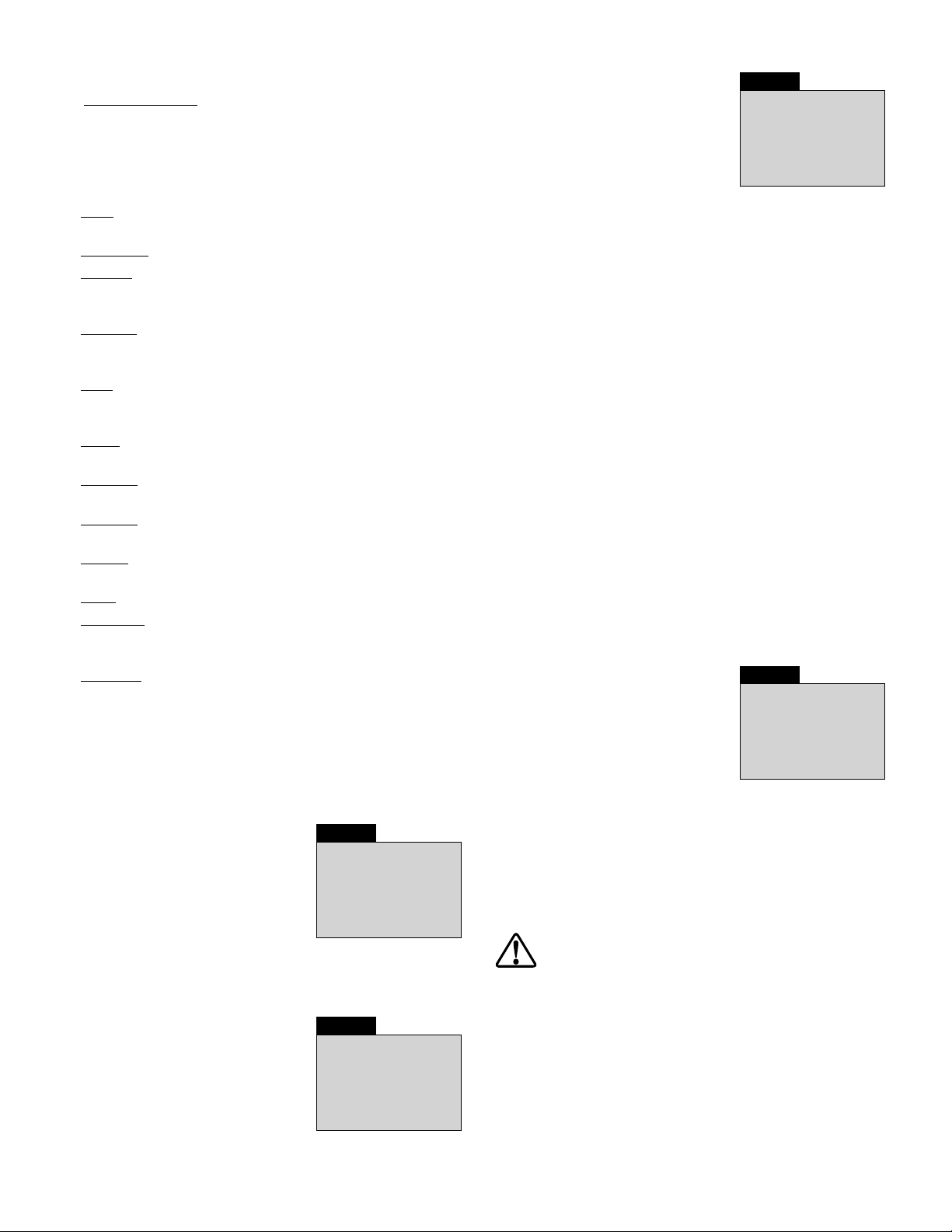
6.3 LCD Operation Buttons
The LCD control panel is equipped with four button switches:
Set Screw
Locknut
Figure 5, Relief Valve
6.0 LCD ELECTRONIC CONTROLS
6.1 LCD Control Panel Overview
The LCD control panel serves as an interface between the
operator and the pump. By using the LCD control panel's fourbutton switches, and the additional button switches located on
the pendant, all functions and settings described in sections 6.3
through 6.6 of this document can be activated.
In the event of an abnormal condition, the LCD also displays
fault codes and warning alerts as described in sections 6.7 and
6.8.
CAUTION: Make sure that the plastic overlay that
protects the LCD screen and the button switches is
not broken or otherwise damaged. Never punch the
button switches with a sharp or pointed instrument, use fi ngertips
only. Clean the overlay regularly with a damp cloth. Never use
aggressive or abrasive detergents.
On/Off / Menu / Down Arrow / Up Arrow
• Pressing the MOTOR on/off button shuts-off the motor during
normal operation. The motor OFF function is available on this
button even if the pump is being operated by the pendant.
However, the MOTOR on/off button will not turn the motor
ON except if the LCD is in Local mode (See section 6.5 K).
• Pressing the MENU button enables the operator to step from
normal operational mode into a series of menus. Repeated
pressing allows the operator to step through all available
menus. Pressing the Menu button also saves any changes
made. To return to the normal operational mode, press and
hold the Menu button for three seconds or do not push any
button for 60 seconds.
• The Down Arrow and Up Arrow buttons serve two purposes.
For most LCD menus, the Down Arrow and Up Arrow buttons
are used to step through the menu options. Also, when the
pump is placed in Local mode, pressing the Up Arrow button
switches the valve solenoid on and off (the pendant is nonoperational in Local mode).
4
6.4 LCD Menu Overview
The LCD contains the following available menus:
• Normal Operation – Default start-up screen. Appears
immediately after power is connected and microcontroller
has booted.
Note: The Units, Automode, Hi Press and Lo Press menus are
available only on pumps equipped with a pressure transducer
(optional equipment)
• Units – Sets the pressure units to PSI / BAR / MPa. PSI is the
default setting.
• Automode – Switches the Automode function ON or OFF.
• Hi Press – (Available only when Automode is ON) Sets the high
pressure limit at which pump de-energizes motor / electric
valve.
• Lo Press – (Available only when Automode is ON - Not used
on pump type 3) Sets the low pressure limit at which pump
energizes motor / electric valve.
• Main – Displays pump status after the desired pump
operational parameters have been input by the user and
saved in the microcontroller memory.
• Motor – Displays the motor hour meter and on/off cycle
counter (non-resettable).
• Low Volt – Displays the low voltage hour meter
(non-resettable).
• Advance – Displays the solenoid hour meter and on/off cycle
counter for the advance solenoid (non-resettable).
• Retract – Displays the solenoid hour meter and on/off cycle-
counter for the retract solenoid (non-resettable).
• Local – Switches the pump Local mode ON or OFF.
• Language – Sets the language of the display to English,
Spanish, French, Italian, German or Portuguese, with English
being the default setting.
• Diagnose – Displays input signals from the pendant and other
electrical accessories.
6.5 LCD Menus
See the following paragraphs for descriptions of the LCD menus.
Also refer to Table 2, Quick Reference Chart (QRC), located at the
end of this document.
6.5 A Normal Operation Menu
(See Screen 1) LCD screen “READY”
indicates that the microcontroller has
booted successfully.
For pumps equipped with a pressure
transducer, the pressure reading will
be displayed as “0” when pump is
fi rst connected to power and motor is
off. Enter into the remaining menus by
pressing the Menu button. Refer to QRC step #1.
6.5 B “Units” Menu
(See Screen 2) This screen allows the
operator to set the unit of pressure
measurement by pressing the Up or
Down Arrow buttons. PSI, BAR and
Mpa are the available choices, with
PSI being the default. Save setting
and step forward by pressing the
Menu button. Refer to QRC step #2.
Screen 1
READY
PSI
0
Screen 2
SET
PSI MPa
UNITS
BAR
6.5 C “Automode” Menu
(See Screen 3) This screen allows the
operator to activate or de-activate
automatic operation of the pump
motor and electric valve (if equipped).
Toggle Automode ON or OFF by
pressing either the Up or Down Arrow
button. Save setting and step forward
by pressing the Menu button. Refer to QRC step #3A.
Notes:
• The UNITS and AUTOMODE menus are available only on
pumps equipped with the pressure transducer option. These
menus will not appear on pumps not equipped with a pressure
transducer.
• When Automode is on, the pump will de-energize the motor
/ electric valve when the hydraulic pressure reaches operator
defi ned levels. This parameter is set using the Automode “HI
PRESS” menu.
• The pump can be set to re-energize the motor / electric valve
when the hydraulic pressure falls to an operator defi ned level.
This parameter is set using the Automode “LO PRESS” menu.
Note: the LO PRESS menu is not functional for pump type 3.
• The specifi c operation of the motor and electric valve while
Automode is activated is determined by the pump type (factory
set). For additional information, refer to Table 4, Pump Model
Matrix, located at the end of this document. Also refer to sections
4.0 and 4.1 for an overview of Automode operation.
• If Automode is OFF: The HI PRESS and LO PRESS menus will
not be available, and any previously set HI or LO PRESS values
will have no effect on pump operation.
Screen 3
SET
AUTOMODE
ON
6.5 D “HI PRESS” Menu
(Available only when Automode is ON)
(See Screen 4) This screen allows the
operator to set the high-pressure limit
at which the pump de-energizes the
motor / electric valve. Make changes
in increments of 50 psi [3.5 bar] by
pressing either Down or Up Arrow
button once. Press and hold either
button to scroll quickly through the
available settings. Maximum pressure value is 10,500 psi [724
bar]. Save setting and step forward to the Main menu (See
section 6.5 F) by pressing the Menu button for 3 seconds. Refer
to QRC step #3B.
Note: If the menu button is pressed for less than 3 seconds, the
selected HI PRESS value will be saved and the LO PRESS menu
(See section 6.5 E) will appear.
CAUTION: Due to motor coast down, valve shift time
and system oil capacitance, always set the user-
adjustable relief valve 200 psi above the HI PRESS
value to prevent pressure spikes. Refer to pump instruction
sheet for relief valve setting instructions.
Screen 4
SET
HI PRESS
7500
PSI
5
 Loading...