

Page 1

POWERFUL SOLUTIONS. GLOBAL FORCE.
L4075 Rev. B 07/14
Index:
English. . . . . . . . . . . . . . . . . . . . . . . . . . . . . . . . . . . . . . 1-18
Español . . . . . . . . . . . . . . . . . . . . . . . . . . . . . . . . . . . . 19-36
Portuguese . . . . . . . . . . . . . . . . . . . . . . . . . . . . . . . . . 37-54
日本語 . . . . . . . . . . . . . . . . . . . . . . . . . . . . . . . . . . . . . 55-72
1.0 SAFETY
1.1 Introduction
Read all instructions carefully. Follow all recommended safety
precautions to avoid personal injury as well as damage to the jack
and/or damage to other property. Enerpac cannot be responsible
for any damage or injury from unsafe use, lack of maintenance
or incorrect operation. Do not remove warning labels, tags, or
decals. In the event any questions or concerns arise, contact
Enerpac or a local Enerpac distributor for clarifi cation.
If you have never been trained on high-pressure hydraulic safety,
consult your distributor or service center for a free Enerpac
Hydraulic Safety Course.
This manual follows a system of safety alert symbols, signal
words and safety messages to warn the user of specifi c hazards.
Failure to comply with these warnings could result in death or
serious personal injury, as well as damage to the equipment or
other property.
The Safety Alert Symbol appears throughout this
manual. It is used to alert you to potential physical
injury hazards. Pay close attention to Safety Alert
Symbols and obey all safety messages that follow this symbol to
avoid the possibility of death or serious personal injury.
Safety Alert Symbols are used in conjunction with certain Signal
Words that call attention to safety messages or property damage
messages and designate a degree or level of hazard seriousness.
The Signal Words used in this manual are DANGER, WARNING,
CAUTION and NOTICE.
DANGER
WARNING
CAUTION
NOTICE
or
NOTICE:
Indicates a hazardous situation that, if not
avoided, will result in death or serious personal
injury.
Indicates a hazardous situation that, if not
avoided, could result in death or serious
personal injury.
Indicates a hazardous situation that, if not
avoided, could result in minor or moderate
personal injury.
Indicates information considered important,
but not hazard related (e.g. messages relating
to property damage). Please note that the
Safety Alert Symbol will not be used with this
signal word.
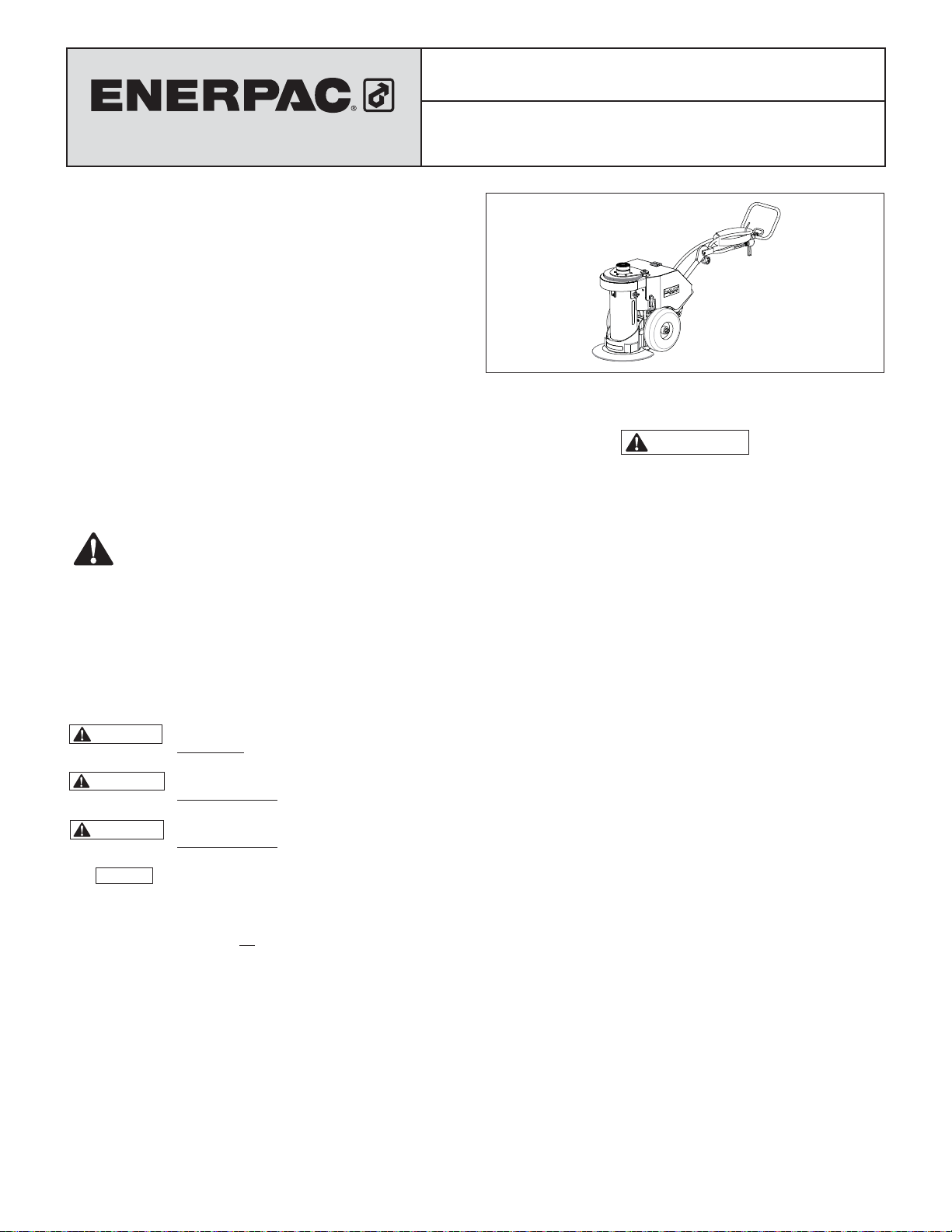
Instruction Sheet
Pow’R-LOCK
™
Portable Lift System
PL200 Series Models (air-operated)
1.2 Safety Precautions - Pow'R-LOCK
System
WARNING
Failure to observe and comply with the following precautions
could result in death or serious personal injury. Property
damage could also occur.
• Keep hands and feet away from hydraulic cylinder and
related components during jack operation.
• Always wear proper personal protective equipment (PPE)
when operating hydraulic equipment (such as gloves, eye
protection, head protection, protective footware, etc.).
• Do not handle pressurized lines. Escaping oil under
pressure can penetrate the skin, causing serious personal
injury. If oil is injected under the skin, see a doctor
immediately.
• The jack is to be used only for lifting loads and for
supporting lifted loads. Never use the jack for pushing
or separating objects, or for other non-lifting related
purposes.
• Never exceed the rated capacity of the jack. Allow for a
margin of safety that accounts for possible shifting loads
or side loading conditions. Failure to follow this warning
could cause the jack to fail.
• Never tamper with overload protection devices. The jack's
internal relief valve must not be repaired or adjusted
except by an authorized service center. The maximum
rated hydraulic pressure of the jack hydraulic system is
10000 psi [700 bar]. Higher settings may result in personal
injury and/or equipment damage.
• Be sure lifting arrangement is stable before lifting load.
Use jack only on a solid and level surface, capable of
supporting the load and the base of the jack. Always
center the load on the load cap of the jack. If the jack is
not perpendicular to the load, slipping or loss of load is
possible.
• Distribute the load evenly when performing lifts with
multiple jacks. Failure to heed this warning may cause loss
of load and/or failure of the jacks.
• Be aware of external events and acts of nature (wind,
storms, fl ooding, earthquakes or other seismic activity,
etc.) that could occur either while the jack is in active use,
or while it is left loaded and unattended. Do not use the
jack if it is likely that such conditions will occur.
1
™
Portable Lift
Page 2
CAUTION
Failure to observe and comply with the following precautions
could result in minor or moderate personal injury. Property
damage could also occur.
• When jack is not in use, fully retract the cylinder and protect
the entire unit from external damage. Keep the jack clean,
avoid weld splatter, and store in a clean dry area. Failure
to observe these precautions may cause erratic operation,
reduced performance, increased wear and/or damage to
jack.
• Keep the jack away from fl ames and heat. For optimum
performance, do not expose the jack to temperatures
above 150 °F [65 °C]. Failure to observe these precautions
may cause erratic operation, reduced performance,
increased wear and/or damage to jack.
• Immediately replace worn or damaged parts with genuine
Enerpac parts. Enerpac parts are designed to fi t properly
and to withstand high loads. Non-Enerpac parts may break
or cause the jack to malfunction.
NOTICE
• The jack is not designed for long-term support of lifted objects.
If the load must remain supported for more than 30 days, use
appropriately rated load support devices to support the load.
• Hydraulic equipment must only be serviced by a qualifi ed
hydraulic technician. For repair service, contact the Enerpac
Authorized Service Center in your area.
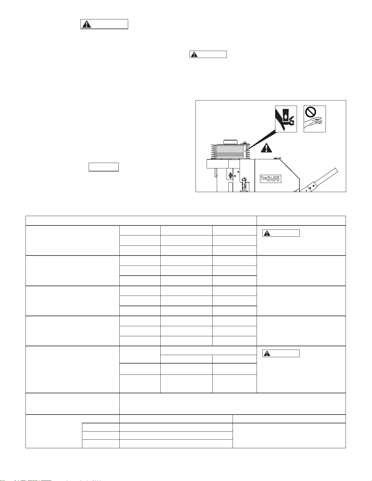
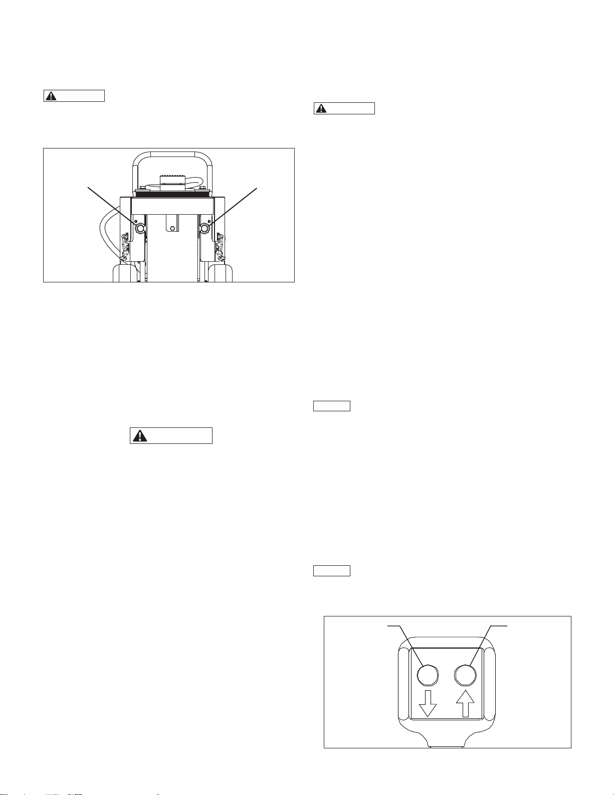
1.3 Crush and Pinch Point Hazard
WARNING
reach in between the cylinder anti-rotation plate and the jack
front access cover. Do not touch or grab the anti-rotation
rods. Do not place hands in or on the cylinder protective
bellows. Serious personal injury can occur if cylinder is
lowered and hands, fi ngers or other body parts are present in
these areas. See Figure 1.
CRUSH AND PINCH POINT HAZARD! Never
Crush and Pinch Point Hazard
Do not reach in this area!
Figure 1, Pinch Point Hazard
2.0 PRODUCT DATA
Table 1 - General Specifi cations (notes and precautions)
Model US Tons kN
Load Rating
(Maximum Capacity)
Weight
Collapsed Height (fully retracted)
Maximum Stroke (fully extended)
Hydraulic Pressure
Cylinder Advance Speed
Compressed Air
Requirements
NOTICE: Specifi cations are subject to change without notice.
Typical 90 - 100 psi [6,2 - 6,9 bar]
Maximum 120 psi [8,3 bar]
PL20014-ASA 200 1779
PL20025-ASA 200 1779
Model Pounds kg
PL20014-ASA 1105 501
PL20025-ASA 1320 599
Model inches mm
PL20014-ASA 34.0 864
PL20025-ASA 45.5 1156
Model inches mm
PL20014-ASA 14.0 356
PL20025-ASA 24.5 622
Model
PL20014-ASA 9898 682
PL20025-ASA 9898 682
Approximately 2.0 to 2.4 inches [51 - 61 mm] per minute.
NOTICE: Actual advance speed will vary depending on available air fl ow, pressure regulator setting,
pump speed, load weight, diameter of incoming air supply line and other variables.
Dynamic Air Pressure Air Flow Volume
Max. Working Pressure at Load Rating
psi bar
130 - 150 CFM [3681 - 4247 l/min]Minimum 50 - 60 psi [3,4 - 4,1 bar]
2
WARNING
jack load rating. Death, serious
personal injury and/or property
damage could result.
Weight includes reservoir fi lled with
oil but does not include accessories,
such as cylinder adapter, extensions
or spacers.
Refer to tables 2 and 3,
item E1.
Refer to tables 2 and 3,
item E2.
WARNING
pressure of the jack hydraulic
system is factory set at 10000 psi
[700 bar]. Do not attempt to
readjust pressure relief valve.
Death, serious personal injury and/
or property damage could result.
Do not exceed
The maximum
Page 3

D
H
B
G
F
A2
E2
A1
C
E1
Table 2 - External Dimensions, PL20014-ASA
A1 A2 B C D E1 E2 F G H
inch mm inch mm inch mm inch mm inch mm inch mm inch mm inch mm inch mm inch mm
38.6 980 64.0 1626 15.7 399 25.4 645 89.9 2283 34.0 864 48.0 1219 14.5 368 5.0 127 23.6 599
NOTICE: Height of items E1 and E2 is with swivel load cap installed. Subtract 2 inches (51 mm) if non-swivel load cap is used.
Dimensions shown are approximate and subject to change without notice.
D
H
E1
G
F
A1
B
A2
E2
C
Table 3 - External Dimensions, PL20025-ASA
A1 A2 B C D E1 E2 F G H
inch mm inch mm inch mm inch mm inch mm inch mm inch mm inch mm inch mm inch mm
38.6 980 64.0 1626 15.7 399 25.4 645 89.9 2283 45.5 1156 70.0 1778 14.5 368 5.0 127 23.6 599
33
Page 4
3.0 PRODUCT DESCRIPTION
The Pow’R-LOCK ™ lifting jack provides continuous positive
locking of the load through all stages of lifting and lowering. No
operator intervention is required to activate or de-activate the
automatic locking system.
Two di erent stroke lengths are available. Both models are
powered by an external compressed air system (user-supplied).
A convenient two-button pendant controls operation of the jack's
air motor and directional control valve.
02
03
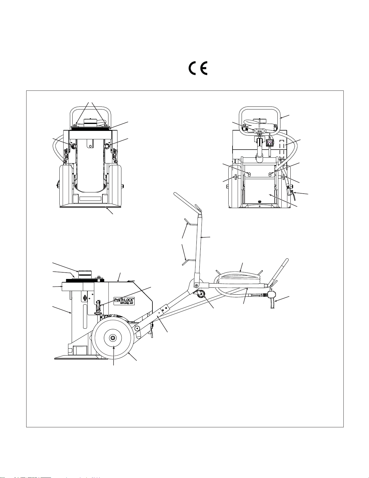
Refer to Section 2.0 for specifi cations, dimensions and other
product data. See Figure 2 for a list of major features and
components.
4.0 CONFORMANCE TO NATIONAL AND
INTERNATIONAL STANDARDS.
Enerpac declares that this product has been tested and
conforms to applicable standards and is approved to
carry the CE mark. An EU Declaration of Conformity is
enclosed separately.
06
05
01 01
04
24
23
22
21
18
19
13
12A
16
08
09
See Fig. 3
08
09
07
10
14
15
12B
11
20
17
Key:
01. Lifting Eye
02. Anti-Rotation Tubes
03. Protective Bellows
04. Jack Base
05. Handle Lock Lever
06. Positioning Handle
07. Air Shut-o Valve
08. Rear Cover Supports
09. Detent Pin
10. Hydraulic Reservoir
11. Wheel and Hub
12A. Upper Handle (raised)
12B. Upper Handle (lowered)
13. Hose Storage Hooks
14. Pendant Hose
15. Pendant Control
16. Caster Wheel
17. Lower Handle
18. Rear Access Cover
19. Rubber Latch
20. Tire
21. Hydraulic Cylinder
22. Front Access Cover
23. Anti-Rotation Plate
24. Load Cap
Figure 2, Major Features and Components, PL200 Series Models (PL20014-ASA shown, PL20025-ASA similar)
4
4
Page 5
5.0 ASSEMBLY AND SETUP
5.1 Important Receiving Instructions
Visually inspect all components for shipping damage. Shipping
damage is not covered by warranty. If shipping damage is found,
notify carrier at once. The carrier is responsible for all repair and
replacement costs resulting from damage in shipment.
NOTICE
The jack rear access cover must be removed to gain
access to various components and service items discussed in
sections 5.2 through 5.4. Refer to Section 7.1 for cover removal
instructions.
5.2 Hydraulic Oil Level
Before using the jack or connecting the air supply, remove the
oil fi ll plug from the hydraulic reservoir and check the oil level.
Add additional hydraulic oil to reservoir if oil level is low. See
Section 7.3 for oil level diagram, oil specifi cations and additional
instructions.
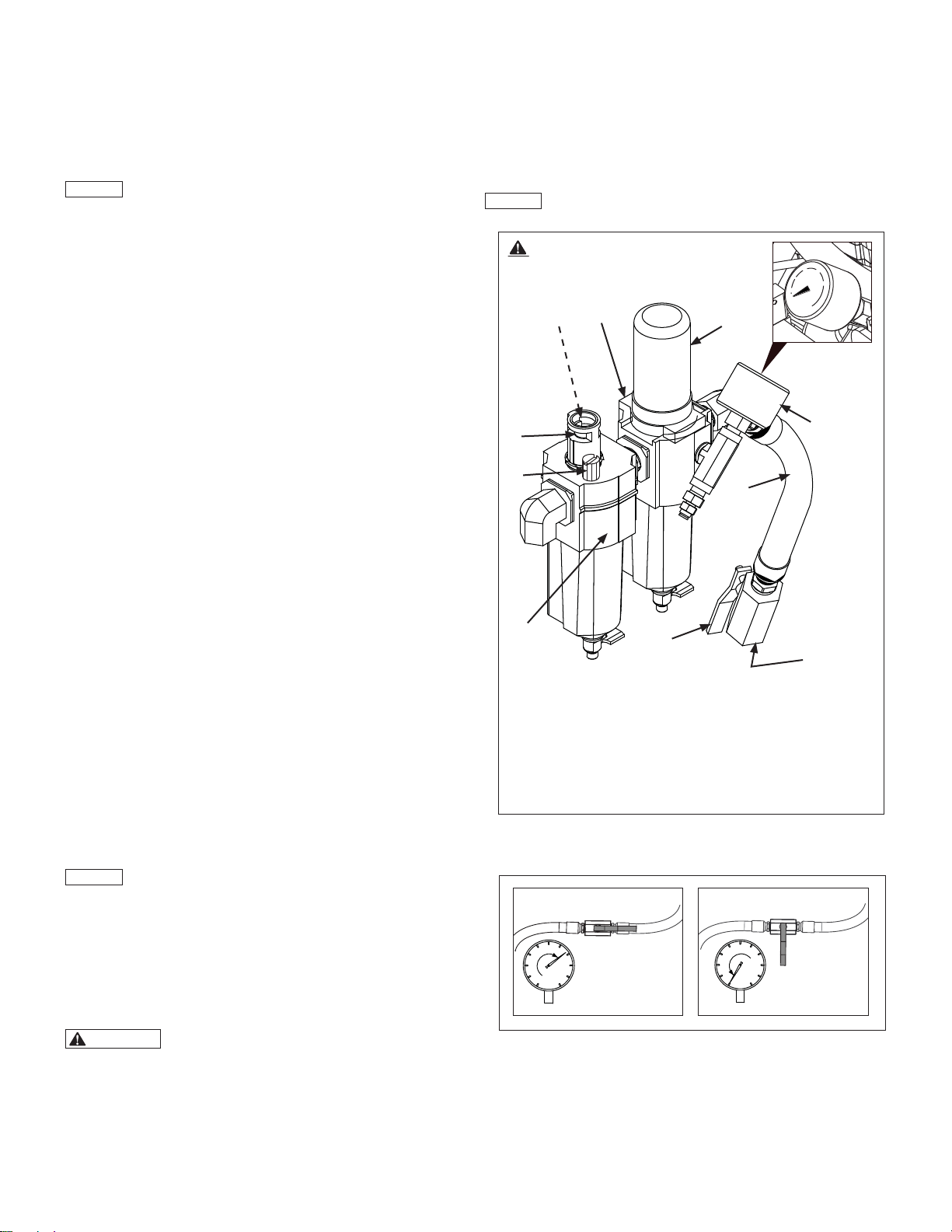
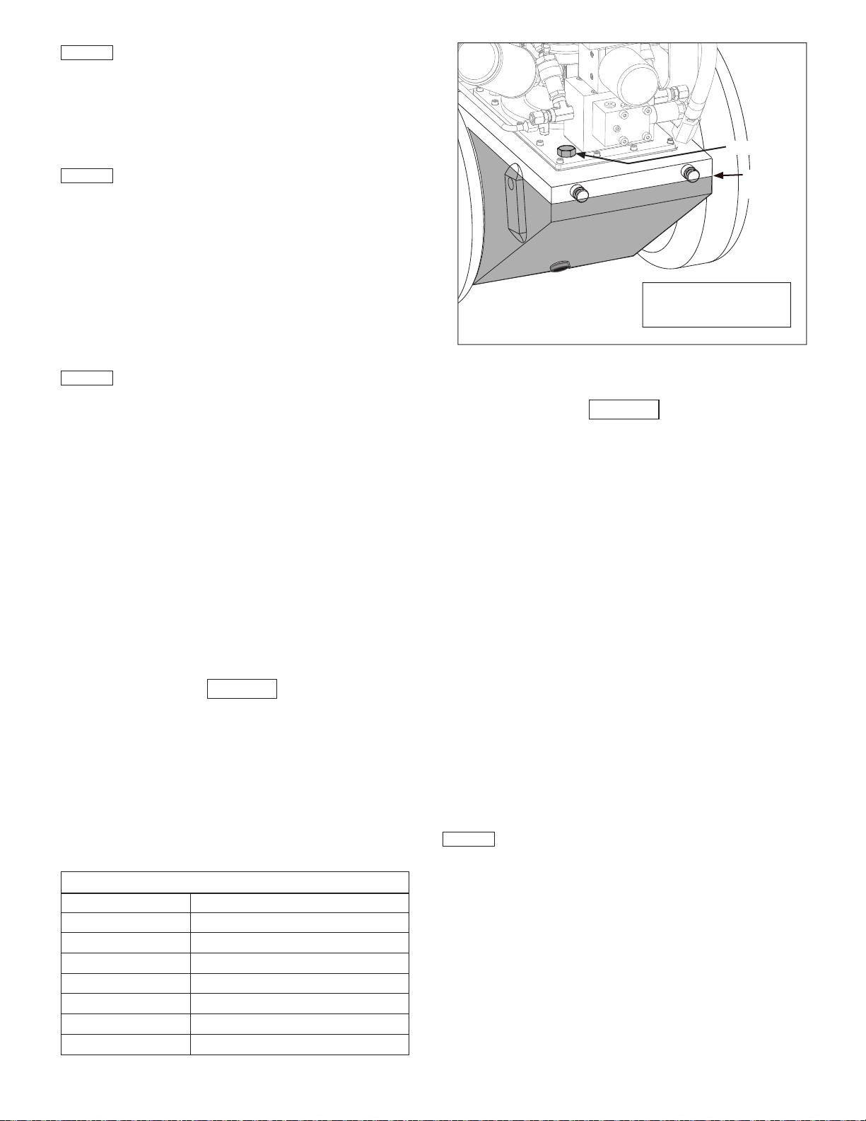
5.3 Compressed Air Requirements
The compressed air system used with the jack must be capable
of providing 80 - 100 psi [5,5 - 6,9 bar] @ 130 CFM [3681 l/min].
The jack is equipped with an air fi lter/regulator assembly, which
consists of an air regulator, pressure gauge and moisture trap.
See Figure 3, items A, B and F.
A short hose connects the fi lter/regulator to the air-shuto valve.
The air inlet connection is a 1/2 inch NPT female thread. See
Figure 3, items C, D and E. Refer to Figure 4 for shut-o valve
positions.
For e ciency of output and reliable operation, an air supply
line of not less than 0.82 inch [20,8 mm] internal diameter is
recommended. (Nominal Pipe Size - 3/4 inch pipe).
Check the air pressure gauge with the pendant UP button
depressed and the jack air motor running. Be sure there is NO
load on the cylinder. This will provide an accurate dynamic air
pressure reading.
The minimum dynamic air pressure required to operate the jack
will vary, but is typically about 50 to 60 psi [3,4 - 4,1 bar].
Approximately 90 to 100 psi [6,2 to 6,9 bar] dynamic air pressure
will be needed for the jack to achieve its rated 200 ton [1779 kN]
lifting capacity.
Lifting speed and torque can be adjusted using the knob located
at the top of the fi lter/regulator. To prevent damage to jack
pneumatic components, the regulator air pressure setting should
not exceed 120 psi [8,3 bar].
NOTICE
in reduced air motor life and will void the Enerpac product
warranty.
Pressure settings of above 120 psi [8,3 bar] will result
Before using the jack, check the lubricant level in the sight gauge
on the air line lubricator. Add additional lubricant if low. Refer to
Section 7.6 for air lubricant recommendations and additional air
lubricator information.
After the air supply hose has been connected, observe the oil
fl ow through the oil drip window while the cylinder is in motion.
Verify that the lubricator drip speed is set at 4 to 5 drops per
minute.
NOTICE
Air motor must be running and cylinder must be
moving up or down when checking lubricator oil drip speed.
Be sure air pressure gauge (item B)
indicates zero (0) psi/bar before
removing lubricator fi ll plug (item H).
0
F
J
I
A
B
H
C
G
E
D
Key:
A. Air Regulator Knob
B. Air Pressure Gauge
C. Air Inlet Hose
D. Air Inlet Connection
(1/2 inch NPT)
E. Air-shuto Valve
F. Air Filter/Regulator
(with moisture trap)
G. Air Line Lubricator
H. Lubricator Fill Plug
I. Oil Drip Window
J. Oil Drip Speed Control
(inside oil drip housing)
Figure 3, Filter/Regulator, Air Line Lubricator
and Air Shut-off Valve
5.4 Air Lubrication
The jack pneumatic system is equipped with an automatic air
line lubricator.
is necessary to provide lubrication for the air motor and to help
prevent rust formation.
WARNING
indicates zero (0) psi/bar before removing lubricator fi ll plug.
Lubricant may spray from fi ll opening if fi ll plug is removed
while system is pressurized, even when air hose has been
disconnected and air shut-o valve is in the closed position.
Serious eye injury and/or skin penetration could result. If any
pressure is indicated, relieve pressure as described in
Section 7.2 of this manual.
See Figure 3, items G, H, I and J.
Lubricated air
Be certain that regulator air pressure gauge
OPEN
CLOSED
Figure 4, Air Shut-Off Valve Positions
5
5
Page 6
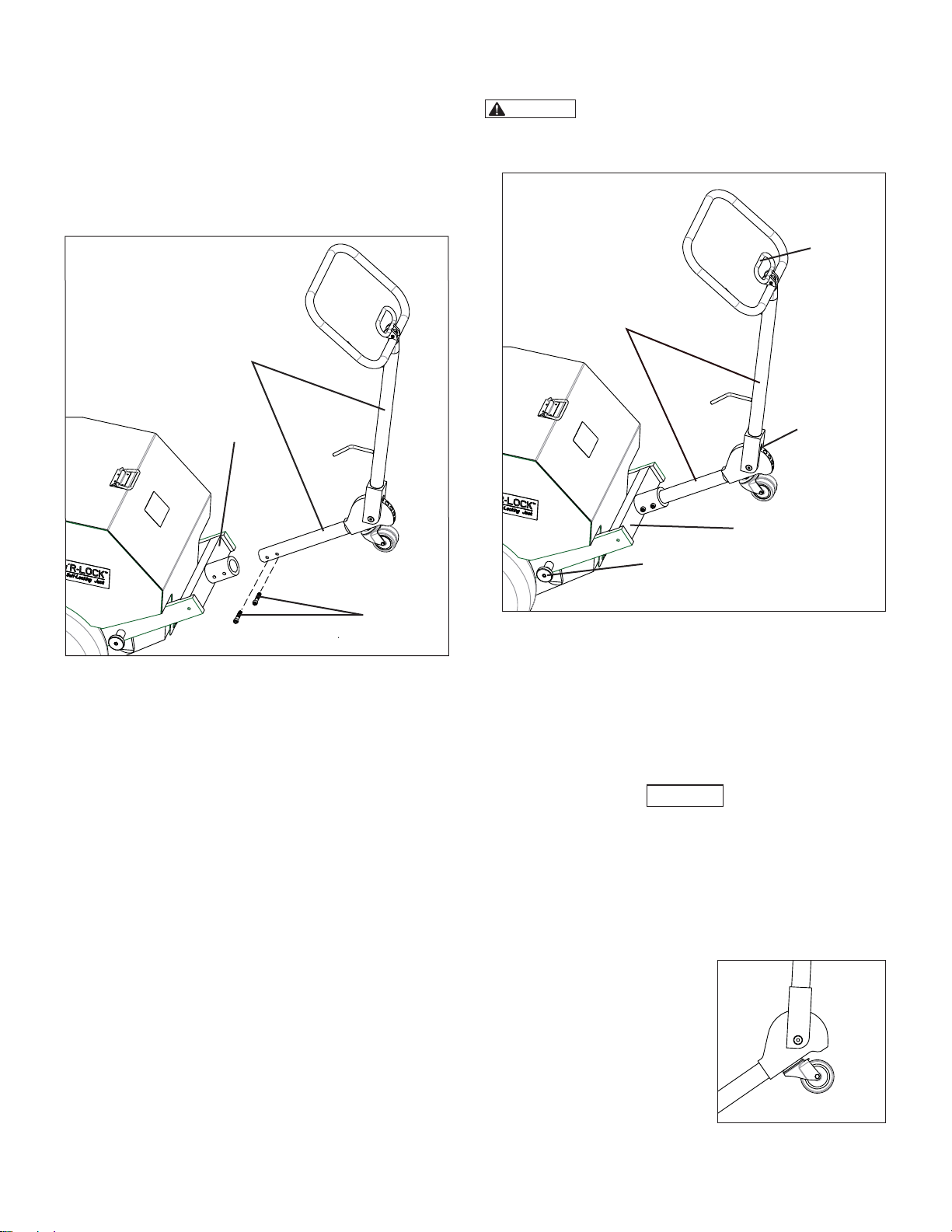
5.5 Upper Handle Installation
The upper handle is shipped unassembled. Install it as described
in the following steps. See Figure 5 for assembly details.
1. Align end of upper handle with opening in lower handle.
Slide upper handle into lower handle until it stops.
2. Secure upper handle with two 3/8-16 inch screws (shipped
loose). Tighten screws to approximately 150 in-lbs [16,9
Nm].
3. Wrap the pendant hose loosely around the hose storage
hooks and hang the pendant control on the upper handle.
Upper Handle
4. After engaging the lock pin and both detent pins, the jack
can now be tilted back onto the wheels and pushed or pulled
to the work area.
CAUTION
Do not walk backwards while pulling the jack.
Always look toward the direction where the jack is being
pulled. Failure to observe this precaution may cause you to
trip and fall, resulting in possible personal injury.
Handle
Lock Lever
Upper Handle
Lower Handle
Screws
(shipped loose)
Figure 5, Upper Handle Installation
5.6 Using the Handle Assembly
The handle assembly is used for transporting the jack on its
wheels and also serves as an aid for positioning the jack under
the jacking point. See Figure 6 for adjustment details.
UPPER HANDLE ADJUSTMENT
1. Push the handle lock lever to release the lock pin.
2. With the lock pin released, position the upper handle to
the desired location. Then, release the handle lock lever to
engage the lock pin.
DETENT PINS - LOWER HANDLE
The detent pins on the lower handle should be engaged in the
corresponding holes on the hydraulic reservoir before tilting the
jack back on its wheels.
To engage the detent pins:
1. Be sure that the detent pins are pulled-out on both sides of
the lower handle.
2. Push down fi rmly on the upper handle. The jack will tilt
forward slightly. Align the detent pins with the detent pin
holes (located on each side of the hydraulic reservoir).
3. While continuing to push down on the upper handle, push
both detent pins inward until they are fully engaged in the
detent pin holes.
Lock Pin
Lower Handle
Detent Pin
(one on each side
of lower handle)
Figure 6, Handle Adjustments
(pendant and hose not shown)
To disengage the detent pins:
1. Push down fi rmly on the upper handle to remove weight
from the detent pins.
2. Pull out the detent pins on both sides of the lower handle.
3. Slowly release hand pressure on the upper handle until the
jack base is resting on the fl oor or ground.
NOTICE
• Be certain that both detent pins are disengaged before using
the jack to lift, support or lower a load. Failure to observe this
precaution may result in damage to the lower handle, wheels,
or axles.
• To closely position the jack under the load, push down on the
upper handle with the detent pins disengaged.
5.7 Caster Wheel
A caster wheel is mounted at the
top end of the upper handle. It
allows the jack to be tilted back
and pushed or pulled to the desired
work location. The caster wheel
can also be used to help maneuver
the jack when it is being positioned
under the jacking point.
For best results, the upper handle
should be adjusted to the most
upright (vertical) position before
using the caster wheel.
6
6
Figure 7, Caster Wheel
Page 7
5.8 Lifting and Supporting the Jack
Two lifting eyebolts are located on the cylinder housing. Use only
these eyebolts when it is necessary to lift or support the jack
for any reason. Always use a suitable lifting device of adequate
capacity. Refer to Section 2.0 for jack weights.
WARNING
support the jack. The handle assembly is not designed for
this purpose. Jack will drop if failure of handle assembly
occurs. Death, serious personal injury and/or property
damage may result.
Lifting
Eyebolt
Never use the handle assembly to lift or
Lifting
Eyebolt
Figure 8, Lifting Eyebolts
6.2 Calculating Load Floor Pressure Requirements
Before the jack is used, it must be verifi ed that the surface
below the jack is capable of supporting the load. The following
calculation will determine the approximate maximum pressure
that will be exerted by the jack against the surface of the fl oor or
ground, based on the load being lifted.
WARNING
fl oor and/or ground can safely support the load to be lifted,
the jack should not be used in that location. Avoid using jack
on overburden or ballast that can shift or crush under load.
Consult a qualifi ed professional, such as a licensed civil
engineer or building architect If there are any questions
or concerns regarding load fl oor pressure requirements.
Failure to observe this instruction may cause an unstable
lifting arrangement, resulting in loss of load, personal injury
and/or property damage.
LOAD FLOOR PRESSURE CALCULATION:
Weight of Load x Load Factor = Load Floor
• The load factor to be used for the imperial system is 0.0125.
• The load factor to be used for the metric system is 0.00194.
If any doubt exists regarding whether the
Pressure Requirement
6.0 OPERATION
6.1 Jacking Safely
You must know the weight of what you intend to lift and choose
a jack with at least 20 percent additional capacity.
All persons operating the jack should obtain and be familiar with
the American National Standards Institute rules that apply to
hydraulic rams and jacks (ASME ANSI B30.1) or the equivalent
standards used in your country or region.
WARNING
Failure to observe and comply with the following precautions
could result in death or serious personal injury:
• Never place any part of your body under the load at any
time while lifting or lowering is in progress. The load could
drop suddenly if it becomes unstable.
• Never leave the jack unattended during operation, even
for a brief period of time. Closely monitor jack operation
at all times and be prepared to stop lifting or lowering
immediately. Load could drop if it is not monitored while
jack is in use.
• Avoid placing external forces on the lifted load while it
is being supported by the jack. The load may become
unstable and fall.
• Do not use the jack outdoors in windy conditions.
Changes in wind direction or velocity could cause the load
to become unstable and fall.
• When lifting with more than one jack, be especially careful
to keep the load level. Leveling is best accomplished by
throttling with the air shut-o valve or by alternating and
stopping jacks to keep the load level enough so it remains
stable and does not drop.
• Never operate the jack with the jack front access cover
raised or removed. Serious personal injury could result
if fi ngers, hands or other body parts become entangled
in the lock nut drive chain mechanism, or in the cylinder
threads.
These load factors are applicable to all Pow’R-LOCK ™ jack
models.
EXAMPLE:
For a 100000 pound [45359 kg] load, the following equations
would apply:
Imperial System: 100000 x 0.0125 = 1250 psi
Metric System: 45359 x 0.00194 = 87.99 kg/cm
NOTICE
of side loading. Excessive side loading will reduce the jack's
e ective foot print on the load fl oor and will increase the jack
contact pressure. Damage to jack components may occur.
The jack is designed to withstand only a limited amount
2
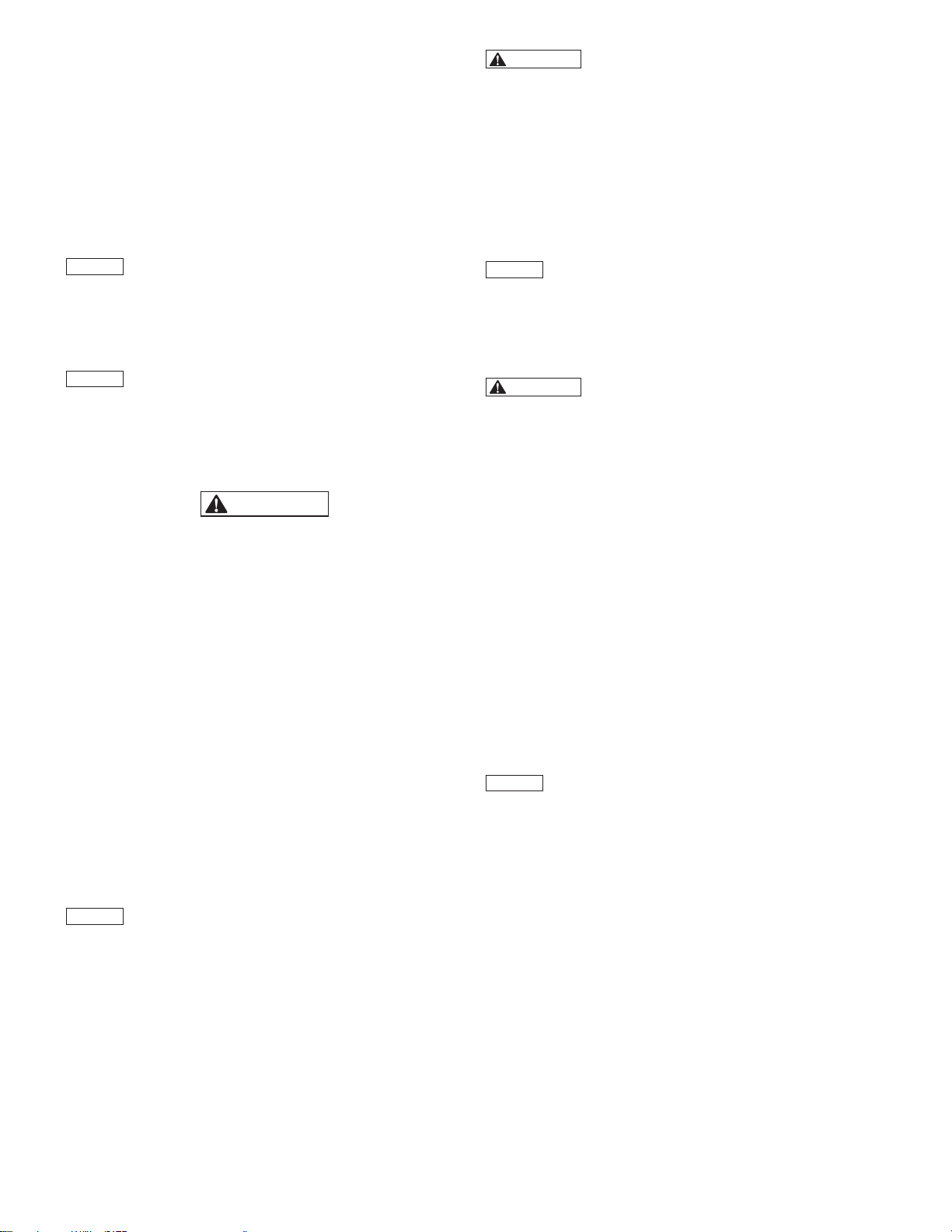
6.3 Pendant Controls
The air motor will start automatically when either pendant button
is depressed. See Figure 9.
• To extend (raise) the cylinder
press and hold the pendant UP button.
• To retract (lower) the cylinder press and hold the pendant DOWN button.
• To stop
release both pendant buttons.
NOTICE
there may be a brief delay until the desired action occurs. A small
amount of time (up to one second) is required for the jack's
pneumatic control circuit to respond to pendant commands.
7
7
the
cylinder and hold the load -
When depressing or releasing either pendant button,
DOWN
BUTTON
Figure 9, Pendant Controls
-
UP
BUTTON
Page 8
6.4 Checking Jack Operation Before Use
Before using the jack for the fi rst time, or if the jack has been
in storage for more than 30 days, check the jack operation as
described in the following steps:
1. If not already done, check the oil level in the hydraulic
reservoir. Refer to Section 7.3 for additional information.
2. Verify that the jack is connected to the compressed
air supply, and that the air pressure setting is correct.
Refer to section 5.3 for air pressure requirements and
recommendations.
3. Be sure that the jack air shut-o valve is in the OPEN position.
NOTICE
to Section 6.3 for pendant control information.
4. Fully extend and retract the cylinder to verify proper
NOTICE
supply is connected and the air-shuto valve is in the OPEN
position. This sound is normal, and indicates that the jack
pneumatic system is pressurized.
Perform the following step with no load on jack. Refer
operation. If needed, continue cycling the cylinder until
operation is smooth, and any trapped air has been removed
from the system.
The jack will make a “hissing” sound when the air
6.5 Operating Instructions
WARNING
Failure to observe and comply with the following precautions
could result in death or serious personal injury. Load may
become unstable or drop. Property damage could also occur.
• Always lift, support and lower the load in accordance with
all applicable work rules and regulations in e ect at your
worksite or facility.
• Wait an appropriate amount of time before working under
the load. Any settling of jack base or load supports (if used)
into the ground below must not exceed 1/4 inch [6,4 mm].
If additional settling occurs, lower the load and reposition
jack on solid ground.
BEFORE BEGINNING THE LIFT:
1. Using the handle assembly, adjust the jack position so that
the cylinder load cap is centered under the jacking point of
the load. Be sure that the jack base is positioned on a solid
and level support surface, with the cylinder perpendicular to
the fl oor or ground.
2. After positioning the jack, be sure that both detent pins on
the lower jack handle are fully pulled out (disengaged).
NOTICE
using jack to lift, support or lower a load. Failure to observe this
precaution may result in damage to the lower handle, wheels, or
axles.
3. If a high jacking point requires a taller jack, install extensions
4. Place a piece of good quality plywood or other compression
Be certain that both detent pins are disengaged before
and/or spacers (optional accessories) on the cylinder as
required. Refer to Section 6.6 for installation instructions and
additional information about extensions and spacers.
material (approximately 1/4 inch [6,4 mm] thick with high
friction characteristics) between the cylinder load cap
and the jacking point. This will provide a small amount of
cushioning and will also help prevent damage to the jacking
point.
WARNING
out of position, resulting in possible loss of load, personal
injury and/or damage to jack. As required, use a swivel load
cap to properly engage an angled lifting point. The slope of
the angled lifting point must not exceed 5 degrees.
TO RAISE THE LOAD:
1. Depress and hold the pendant UP button. The air motor will
start and the cylinder will begin extending.
2. When the load has reached the desired height, release the
pendant UP button. The cylinder will stop and the load will
remain supported.
NOTICE
load holding device, the use of auxiliary stands, blocking or other
additional load supports may be required in your location. Follow
all applicable work rules and regulations in e ect at your facility
or worksite.
TO LOWER THE LOAD:
WARNING
load is lowered evenly, so that load shifting does not occur.
Load shifting could cause instability, which could result in
loss of load and/or failure of the jack. This could cause death,
serious personal injury and/or property damage.
1. Be certain that no persons are working under the load. Alert
all personnel that the load is about to be lowered.
2. Depress and hold the pendant DOWN button. The air motor
will start and the cylinder will advance a slight amount to
raise and release the cylinder lock nut. The cylinder will then
begin to retract.
3. When the load has been lowered to the desired height,
release the pendant DOWN button. The air motor will stop.
AFTER COMPLETING THE JOB:
1.
Fully retract the cylinder.
the jack air-shuto valve.
2. To remove trapped pressure from the jack pneumatic system,
depress and hold the pendant UP button. The air motor may
run for a few seconds but will stop when pressure is relieved.
3. Always store the jack and its accessories in a clean and dry
area, free of moisture and direct sunlight.
NOTICE
top of the cylinder when jack is not in use. This will prevent water
from accumulating inside the recessed area at the top of the
cylinder.
Jacking at an angle can allow the jack to slip
Although the Pow’R-LOCK ™ jack is designed to be a
Be careful while lowering to ensure that the
Disconnect the air supply hose from
Always keep a load cap or extension installed in the
6.6 Stacking Instructions - Extensions and Spacers
Extensions and spacers are available as optional accessories
from your Enerpac authorized distributor. Refer to tables 4 and
5 for additional information.
PLE Series extensions allow the jack's usable lifting height to be
increased up to 9 inches [229 mm] for model PL20025-ASA and
up to 28 inches [711 mm] for model PL20014-ASA.
PLS Series spacers allow additional fi ne adjustment of the usable
lifting height. They may be used alone or in conjunction with
PLE Series extensions. Spacers of 1 and 2 inch [25 and 51 mm]
heights are available.
8
Page 9
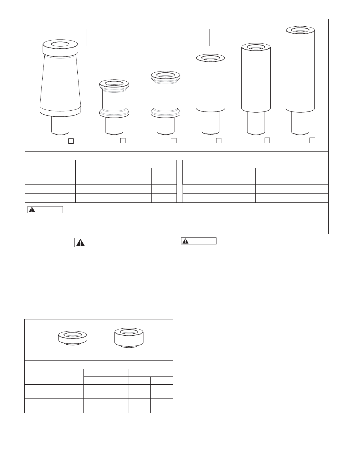
▲
Use with jack model PL20014-ASA only.
▼
Use with jack model PL20014-ASA or PL20025-ASA.
PLB12 PLE5 PLE7 PLE9 PLE11 PLE14
▲
▼ ▼ ▼
▲
▲
Table 4 - PLB and PLE Series Extensions (optional accessories)
Extension
Model
PLB12 12 305 44.2 20,0 PLE9 9 229 28.0 12,7
PLE5 5 127 24.6 11,2 PLE11 11 279 31.7 14,4
PLE7 7 178 29.9 13,6 PLE14 14 356 37.4 17,0
WARNING
Extensions PLE11, PLB12 or PLE14 are to be used with the “short” jack model PL20014-ASA only. Use of
Height (each) Weight (each)
inches mm pounds kg inches mm pounds kg
Extension
Model
Height (each) Weight (each)
these extensions on “tall” jack model PL20025-ASA will result in an excessive maximum lifting height. Load could become
unstable and drop, resulting in possible personal injury and/or property damage.
NOTICE: Dimensions and weights shown are approximate.
WARNING
Failure to observe the following precautions and instructions
may allow the load to shift or drop, resulting in possible
personal injury and/or property damage.
• Use only genuine Enerpac PLB, PLE and PLS Series
extensions and spacers with the Pow’R-LOCK ™ jack.
Never use extensions or spacers that are fabricated or that
are designed for use with another lifting device.
• Never exceed the maximum additional stack height for your
jack model. Refer to Table 6 for additional information. An
excessive stack height will reduce the stability of the jack.
WARNING
precautions, and conditions could result in an unstable lifting
arrangement. Load could shift or drop, resulting in possible
personal injury and/or property damage.
When using PLB, PLE or PLS Series extensions and spacers,
always obey the following rules, precautions, and conditions:
• Table 6 shows the maximum additional stack height (dimension
“X”) that is allowed. When installing extensions and spacers,
do not exceed this dimension for your jack model.
• The total height of the PLS Series spacers installed in the stack
must not exceed 2 inches [51 mm].
Failure to observe the following rules,
• Jack model PL20014-ASA: Only one PLB12 base extension
(if used) must be present in the stack, and the PLB12 must
always be located at the bottom of the stacking arrangement.
Do not attempt to stack two or more PLB12's together.
• Extensions PLE11, PLB12 and PLE14 are designed for use
PLS1
PLS2
with model PL20014-ASA only. To prevent unsafe operation,
do not use these extensions on jack model PL20025-ASA (see
Table 5 - PLS Series Spacers (optional accessories)
Spacer Model
Height (each) Weight (each)
inches mm pounds kg
warning statement at bottom of Table 4).
• Be especially careful to avoid o -center loads and side loads
when using extensions and spacers.
PLS1 1.0 25 4.5 2,0
PLS2 2.0 51 9.1 4,1
NOTICE: Dimensions and weights shown are approximate.
9
Page 10
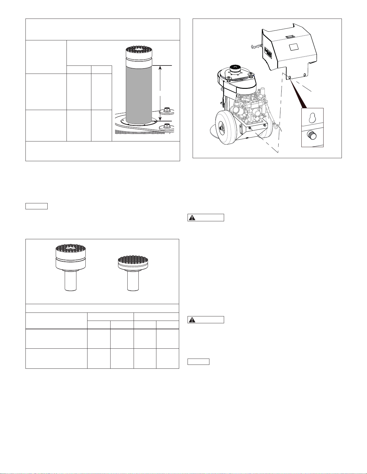
Table 6 - Maximum Additional Stack Height
(Using optional PLB and PLE Series
extensions and PLS Series spacers)
Maximum
Additional
Jack Model
Stack Height
(dimension “X”)
inches mm
PL20014-ASA 28.0 711
PL20025-ASA 9.0 229
Stack height (dimension “X”) includes total combined height of all
installed extensions and spacers. Load cap height is NOT included in
the stack height.
X
6.7 Load Caps
A swivel load cap is included with the jack as standard equipment.
A non-swivel load cap is available as an optional accessory, and
is for use in applications where a reduced collapsed height is
needed. Refer to Table 7 for load cap model numbers.
NOTICE
points. A swivel load cap should always be used when the
amount of misalignment between a non-swivel load cap and the
lifting point is too large to be compensated for by use of plywood
or other suitable high-friction compression material alone.
Use a swivel load cap to properly engage angled lifting
Figure 10, Rear Access Cover Removal
3. Gently guide the cover rearward until it has cleared the pins
and then lift the cover o of the jack.
4. Reverse steps 1, 2 and 3 to reinstall the cover. At the keyway
openings, be sure the groove in each cover support pin is
aligned with the cover sheet metal before fully installing the
cover onto the jack.
WARNING
Always reinstall the jack rear access cover
before using the jack. Except as necessary for maintenance
procedures, do not operate jack with cover removed. Serious
personal injury could occur if persons make contact with hot
surfaces or pressurized lines and components while cover is
removed. Damage could also occur if falling objects drop
onto exposed components.
DD4880045SR PLC1
Table 7 - Load Caps
Load Cap Model
DD4880045SR
Swivel Load Cap
(standard)
PLC1
Non-swivel Load Cap
(optional accessory)
NOTICE: Dimensions and weights shown are approximate.
Height (each) Weight (each)
inches mm pounds kg
3.3 84 20.2 9,2
0.88 22 10.4 4,7
7.0 MAINTENANCE
7.1 Rear Access Cover Removal
The jack rear access cover must be removed to gain access to
various inspection, lubrication and maintenance points. Remove
the jack rear access cover as described in the following steps:
1. Unhook the rubber latches on each side of the cover.
2. Pull up on the cover until the round openings on the cover
keyways align with the cover support pins on the rear of the
hydraulic reservoir.
7.2 Depressurizing the Jack Hydraulic and Pneumatic
Systems
For some maintenance procedures contained in Section 7 of
this manual, it is required that the jack hydraulic and pneumatic
systems be depressurized before the procedure can begin. These
operations are necessary to ensure the safety of the maintenance
personnel.
WARNING
steps may result in unexpected start-up of jack while
maintenance and repair procedures are being performed.
Uncontrolled release of pressure may also occur if
pressurized components are opened or pressurized fi ttings
are loosened. Serious personal injury could result.
NOTICE
before the pneumatic system is depressurized. Always be sure to
depressurize both systems.
1. Depressurize the jack hydraulic system, as described in
steps 1a through 1c:
a. Check that the jack is connected to the air supply and the
air-shuto valve is in the OPEN position.
b. Be sure the cylinder is in the fully retracted position.
c. Depress the pendant UP button while watching the
cylinder. Release the UP button IMMEDIATELY when the
cylinder starts advancing (usually after about 1 or 2 seconds).
This procedure will relieve any trapped pressure in the jack
hydraulic system.
10
Failure to follow the procedure in the following
The hydraulic system must be depressurized fi rst,
Page 11
NOTICE
To prevent hydraulic pressure from re-building in the
system, do not depress the pendant DOWN button at any time
during the following steps.
2. Depressurize the jack pneumatic system, as described in
steps 2a through 2f:
a. Move the jack air-shuto valve to the CLOSED position.
b. Disconnect air supply hose at jack air-shuto valve.
NOTICE
Jack may start and run briefl y in the following step, as
trapped air is expelled from the jack pneumatic system.
c. Depress and hold the pendant UP button. Continue
holding button until jack air motor stops running. Motor will
usually stop after about 2 to 6 seconds, depending on length
of air supply hose.
d. Verify that there is no audible “air hiss” sound coming
from the jack.
e. Remove the jack rear access cover (if not already
removed). Refer to Section 7.1.
f. Check the air pressure gauge on the jack fi lter/lubricator.
Verify that it indicates zero (0) psi/bar.
NOTICE
If any pressure is indicated on gauge, be certain that
air-shuto valve is in the CLOSED position and that air hose is
disconnected from air shut-o valve. Then, repeat steps 2c
through 2f.
3. Proceed with desired maintenance or repair procedure.
7.3 Checking Oil Level
Check the hydraulic oil level every 90 days.
1. Be sure that cylinder is fully retracted and that the jack is
positioned on a fi rm and level surface.
2. Remove the jack rear access cover. Refer to Section 7.1.
3. Be sure the air shut-o valve is in the CLOSED position.
4. Unscrew and remove the oil fi ll plug. See Figure 11.
5. Check the oil level in the reservoir. Oil level should be
approximately 1 inch [25 mm] below top of reservoir, with
cylinder fully retracted and air motor turned o . See Figure 11.
6. If oil level is low, add Enerpac HF hydraulic oil as required.
Use a funnel to avoid spillage.
NOTICE
• Reservoir is vented. To prevent oil leakage through the air
breather, do not fi ll reservoir completely to the top.
• To help avoid accidental overfi lling of reservoir, always make
sure that cylinder is fully retracted before checking oil level or
adding additional oil.
• If Enerpac HF is not available at the worksite, use an equivalent
hydraulic oil that meets the specifi cations shown in Table 8.
7. Reinstall oil fi ll plug.
8. Reinstall the jack rear access cover. Refer to Section 7.1.
Table 8 - Hydraulic Oil Specifi cations - ISO 32
ISO Grade
Viscosity Index 100 min
Viscosity at 210
Viscosity at 100
Viscosity at 0
API Gravity
Flash, C.O.C.
Pour Point,
°F
°F
°F
°F
°F
32
42-45 S.U.S.
150-165 S.U.S.
<12000 S.U.S.
31.0-33.0
400
-35
Oil Fill Plug
Oil Level
(FULL)
FULL = 1 inch [25 mm]
below top of reservoir
Figure 11, Oil Level - Hydraulic Reservoir
(handle assembly removed to show detail)
NOTICE
• Failure to use the proper oil may result in damage to jack
hydraulic components and will void the product warranty. Use
of Enerpac HF oil is strongly recommended.
• Be sure that the oil is clean. The oil cleanliness should be
maintained to a maximum level of 18/16/13 per the ISO4406
standard. If the oil has a milky, cloudy or dark appearance, it
should be changed immediately as described in Section 7.4.
7.4 Changing the Oil
Change the oil in the hydraulic reservoir every 12 months or 500
hours of use. See Figure 12.
The following conditions will require more frequent oil changes:
• Rigorous duty, where oil temperature may reach 150 °F
[60 °C].
• A high humidity environment and/or extreme changes in
temperature that can result in condensation inside the reservoir.
• Dirty or dusty environments that may contaminate the oil.
Change the oil as described in the following steps:
1. Be sure that cylinder is fully retracted.
2. Remove the jack rear access cover. Refer to Section 7.1.
3. Completely relieve any trapped pressure in the jack hydraulic
and pneumatic systems. Disconnect the air supply hose
from the air shut-o valve. Follow procedure in Section 7.2.
NOTICE
[18,9 liter] of oil when fi lled to the proper level with cylinder fully
retracted and air motor o . Dispose of used oil in accordance
with all applicable laws and regulations.
4. Loosen and remove oil drain plug at bottom of reservoir.
5. Clean and reinstall oil drain plug.
6. Remove, clean and reinstall the reservoir air breather.
7. Using a strap wrench, unscrew and remove the old oil fi lter.
11
The hydraulic reservoir holds approximately 5 gallons
Allow used oil to drain into a suitable container. It may be
necessary to tip the jack back slightly to completely drain all
oil and any debris from the bottom of the reservoir.
Replace the air breather if clogged or damaged.
Catch any spilled oil in a suitable container. Dispose of spilled
oil in accordance with all applicable laws and regulations.
Page 12

NOTICE
Use only a new 10 micron oil fi lter of the proper
specifi cations (Enerpac Part No. 69670E or equivalent).
8. Before installation, lubricate the new oil fi lter's rubber seal
with a small amount of oil. Tighten fi lter hand tight only (do
not use tools).
4
1
2.
Key:
1. Air Breather
2. Oil Fill Plug
Figure 12, Oil Change
(handle assembly removed to show detail)
9. Remove the oil fi ll plug and add Enerpac HF hydraulic oil as
required. Use a funnel to avoid spillage. Oil level should be
approximately 1 inch [25 mm] below top of reservoir, with
cylinder fully retracted and air motor turned o . See Figure
11 for oil level diagram.
3.
3. Oil Drain Plug
4. Oil Filter
NOTICE
• Reservoir is vented. To prevent oil leakage through the air
breather, do not fi ll reservoir completely to the top.
• To help avoid accidental overfi lling of reservoir, always make
sure that cylinder is fully retracted before checking oil level or
adding additional oil.
• If Enerpac HF is not available at the worksite, use an equivalent
hydraulic oil that meets the specifi cations shown in Table 8.
10. Clean the oil fi ll plug and apply thread sealant to the threads.
Reinstall oil fi ll plug.
WARNING
In the following step, it will be necessary to
extend and retract the cylinder several times. Stay clear of
the cylinder and related components. Keep hands and fi ngers
away from pinch and crush points. Serious personal injury
could occur if these precautions are not observed. Refer to
Section 1.3 of this manual for additional hazard information.
11. With no load on the jack, extend and retract the cylinder
several times to check for proper operation, and to remove
any trapped air in the hydraulic system.
12. With the cylinder fully retracted and the pump motor o ,
re-check oil level to be sure that it has not dropped. Add
additional oil if required. See Figure 11 for oil level diagram.
13. Reinstall the jack rear access cover. Refer to Section 7.1.
7.5 Air Line Filter/Regulator (See Figure 13)
Every 30 hours of operation:
1. Remove the jack rear access cover. Refer to Section 7.1.
2. Completely relieve any trapped pressure in the jack hydraulic
and pneumatic systems. Disconnect the air supply hose
from the air shut-o valve. Follow procedure in Section 7.2.
3. Check the fi lter bowl sight gauge for water. A manual drain is
located at the bottom of the fi lter/regulator bowl. If water is
present, drain it into a suitable container and dispose of it in
accordance with all applicable laws and regulations. Be sure
the drain is fully closed after draining is completed.
Rear View
K
Key:
A. Air Regulator Knob
B. Air Pressure Gauge
C. Air Inlet Hose
D. Air Inlet Connection
(1/2 inch NPT)
E. Air-shuto Valve
Figure 13, Routine Service and Maintenance Items - Air Filter/Regulator and Air Line Lubricator
F
G
(item B) indicates zero (0) psi/bar
before removing lubricator fi ll
plug (item H) or performing
maintenance activities.
M
L
F. Air Filter/Regulator
(with moisture trap)
G. Air Line Lubricator
H. Lubricator Fill Plug
I. Oil Drip Window
J. Oil Drip Speed Control
Be sure air pressure gauge
K. Filter Bowl Sight Gauge
L. Drain Valves
M. Lubricant Bowl Sight Gauge
N. Lubricant Bowl
O. Filter Bowl
12
J
A
B
I
H
N
O
Front View
C
E
D
Page 13
4. Remove fi lter bowl and inspect the air fi lter element (inside
fi lter bowl). Replace fi lter element if dirty.
NOTICE
Norgren for detailed maintenance instructions, fi lter elements
and replacement parts.
Filter/regulator is manufactured by Norgren. Contact
7.6 Air Line Lubricator (See Figure 13)
Every 30 hours of operation:
1. Remove the jack rear access cover. Refer to Section 7.1.
2. Check the sight gauge on the air line lubricant bowl. The
lubricant level should be at least 1/2 full.
NOTICE
described in steps 3 through 6. If lubricant level is OK, skip these
steps and go to step 7.
3. Completely relieve any trapped pressure in the jack hydraulic
completely depressurized and regulator air pressure gauge
indicates zero (0) psi/bar before removing lubricator fi ll plug.
Lubricant may spray from fi ll opening if fi ll plug is removed
while system is pressurized, even when air hose has been
disconnected and air shut-o valve is in the closed position.
Serious eye injury and/or skin penetration could result.
4. Remove the lubricator fi ll plug. Add additional lubricant as
For ambient temperatures above 32°F [0°C], use a high quality
NOTICE
gauge. Do not operate jack with excess lubricant in lubricant
bowl. If lubricant bowl is overfi lled, jack air logic circuit may
become fl ooded with lubricant, preventing normal operation
of jack.
5. Reinstall the lubricator fi ll plug.
6. Reconnect the air supply hose. Be sure the air shut-o valve
7. Check the lubricator drip speed in the drip window:
• Drip speed should be 4 to 5 drops per minute. Always check
• If drip speed is too slow or too fast, readjust the drip speed
NOTICE
Norgren for detailed maintenance instructions, fi lter elements
and replacement parts.
8. Reinstall the jack rear access cover. Refer to Section 7.1.
If lubricant level is low, add additional lubricant as
and pneumatic systems. Disconnect the air supply hose
from the air shut-o valve. Follow procedure in Section 7.2.
WARNING
required, until the level reaches the top of the lubricant bowl
sight gauge. DO NOT OVERFILL!
SAE 10 [ISO 32] air tool lubricant. For ambient temperatures
below 32°F [0°C], use only a glycol-based anti-freeze air tool
lubricant (Enerpac part number DD5142835 or equivalent).
is in the OPEN position.
the drip speed while the cylinder is advancing or retracting.
as required. Use a fl at blade screwdriver to turn the drip
speed adjustment screw.
Be certain that jack pneumatic system is
Lubricant level must not be higher then top of site
Air line lubricator is manufactured by Norgren. Contact
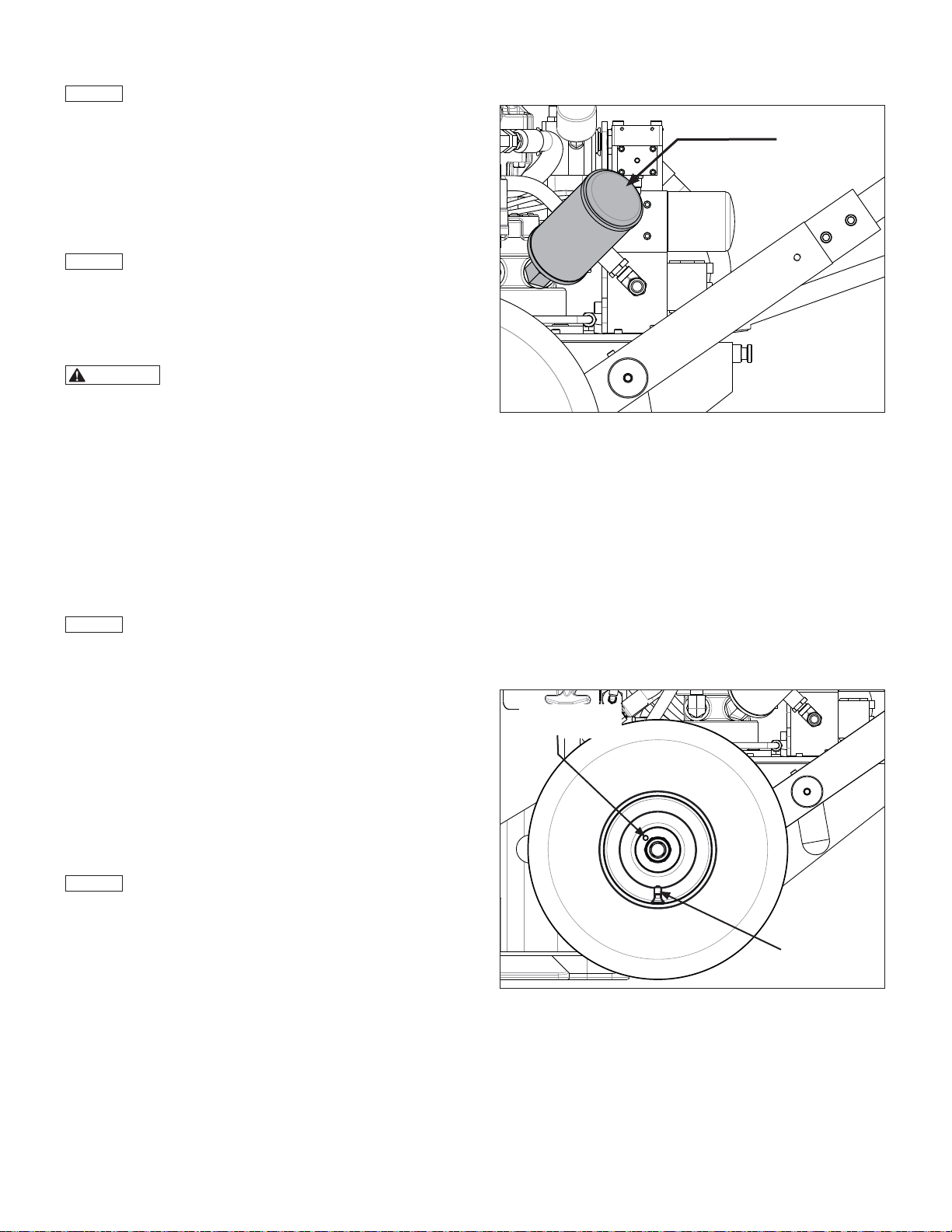
7.7 Air Mu er (See Figure 14)
Every 30 hours of operation:
1. Remove the jack rear access cover. Refer to Section 7.1.
2. Disconnect the air supply hose from the air shut-o valve.
Completely relieve any trapped air in the jack pneumatic
system. Follow procedure in Section 7.2.
3. Inspect the air mu er. Remove any loose dirt or debris.
4. If old air mu er is very dirty or clogged, replace it with a new
air mu er. Use only a 25 micron air mu er of the original
specifi cations (Enerpac Part No. DD4791116 or equivalent).
Air Mu er
Figure 14, Air Muffler
7.8 Wheels and Tires (See Figure 15)
Every 30 hours of operation:
• Check the tires for wear or damage. Replace as required.
• Check the tire infl ation pressure. Each tire should be infl ated
to 90 psi [6,2 bar].
Every 12 months:
• Each wheel hub contains a grease fi tting. Lubricate both wheel
bearings with a high quality wheel bearing grease.
• Inspect the caster wheel for damage and check that it turns
and pivots freely. Remove any loose dirt and lubricate bearings
with oil. Refer to Figure 7 in Section 5.7 of this manual.
Wheel Bearing
Grease Fitting
Tire Air Valve
Figure 15, Wheels and Tires
13
Page 14
7.9 Lubrication of Cylinder Threads and Lock Nut
Chain Drive (See Figures 16-19)
The cylinder threads and lock nut drive chain should be lubricated
approximately every 30 hours of operation. Both lubrication
activities can be performed at the same time, as described in the
following steps:
1. Be sure there is no load on the jack.
2. Unhook the rubber latches and remove the jack rear access
cover. See Section 7.1 for procedure.
NOTICE
must be fully extended and the jack pneumatic system must be
depressurized. Follow instructions in steps 3a-3f.
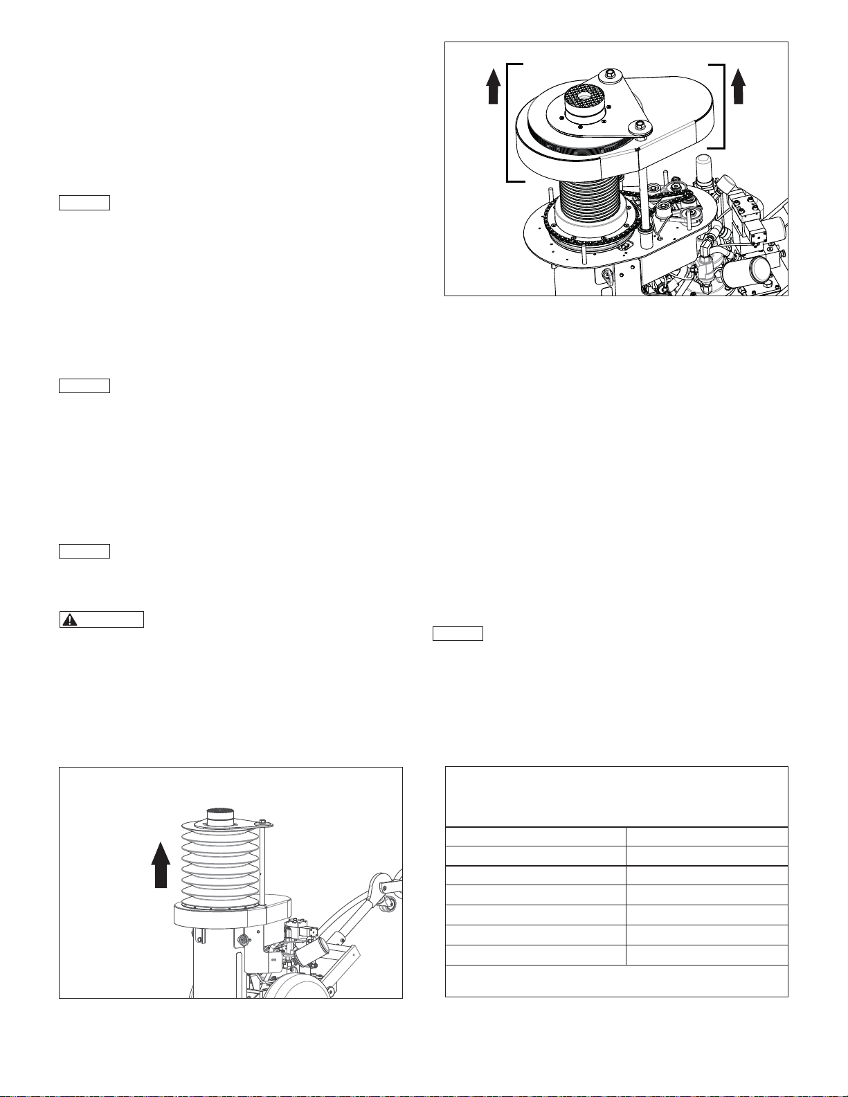
3. Fully extend the cylinder and depressurize the jack pneumatic
a. Depress and hold the pendant UP button to raise the
b. Move the jack air-shuto valve to the CLOSED position.
c. Disconnect air supply hose at jack air-shuto valve.
NOTICE
trapped air is expelled from the jack pneumatic system.
d. Depress and hold the pendant UP or DOWN button.
e. Verify that there is no audible “air hiss” sound coming
f. Check the air pressure gauge on the jack fi lter/lubricator.
NOTICE
air-shuto valve is in the CLOSED position and that air hose is
disconnected from air shut-o valve. Then, repeat steps 2d
through 2f.
and that air regulator pressure gauge indicates zero (0) psi/
bar before continuing with this procedure. Jack will start
immediately if air pressure is indicated on gauge, and either
pendant button is depressed. Lock nut and chain will begin
turning. Serious personal injury could occur if jack is started
while persons are performing lubrication procedures.
4. Raise the jack front access cover so that the cylinder threads
Before performing lubrication procedures, the cylinder
system:
cylinder. Continue holding the button until the cylinder is
fully extended and the jack air motor stops running. See
Figure 16.
Jack may start and run briefl y in the following step, as
Continue holding button until jack air motor stops running.
Motor will usually stop after about 2 to 6 seconds, depending
on length of air supply hose.
from the jack.
Verify that it indicates zero (0) psi/bar.
If any pressure is indicated on gauge, be certain that
WARNING
Be certain that air supply hose is disconnected
are exposed as much as possible. See Figure 17.
Figure 17, Lifting Front Access Cover to Expose Threads
5. Attach a lifting sling to the front access cover. Wrap the sling
around the anti-rotation plate and load cap, so that the cover
is held in the raised position. Be certain that the sling is strong
enough to support the weight of the cover (approximately 15
lbs [5,6 kg] ) and that it is securely fastened.
6. Perform the following inspection and lubrication tasks. See
Figure 18.
• Remove any loose dirt or debris from the chain drive
assembly.
• Check each chain tensioner to verify that it is applying
fi rm spring tension against the chain. If the tensioner does
not move freely, or if spring tension is weak, it should be
replaced. The tensioners are not adjustable or repairable.
• Check the tensioner rollers for obvious indications of wear
or damage. Replace rollers as required. The rollers are
available as a separate replacement part.
• Check all teeth on the lock nut and drive sprockets for
obvious indications of wear or damage. Replace these
parts as required.
NOTICE
Refer to Table 9 for gear oil specifi cations.
• Apply a fi lm of SAE 80w-90 gear oil [ISO 150] to the links
of the lock nut drive chain.
• At each tensioner, apply a small amount of 80w-90 gear
oil [ISO 68] to the exposed areas of the tensioner pivot
bushing, located under the tensioner retaining nut. Some
of the oil will fl ow past the bushing and onto the tensioner
pivot shaft. Removal of nut is not required.
Figure 16, Fully Extending the Cylinder
Table 9 - Gear Oil Specifi cations - SAE 80w-90 [ISO 150]
(Use for lubricating cylinder threads, lock nut drive
chain, sprockets and tensioner pivot shaft.)
SAE Grade
ISO Grade
Viscosity Index 103
Viscosity at 40
Viscosity at 100
Flash Point.
Pour Point,
NOTICE: Specifi cations shown in this table are typical. Exact
specifi cations may di er slightly, depending on oil brand.
14
°C, cSt
°cSt
°C
°F
80w-90
150
136
14.5
202
-30
Page 15
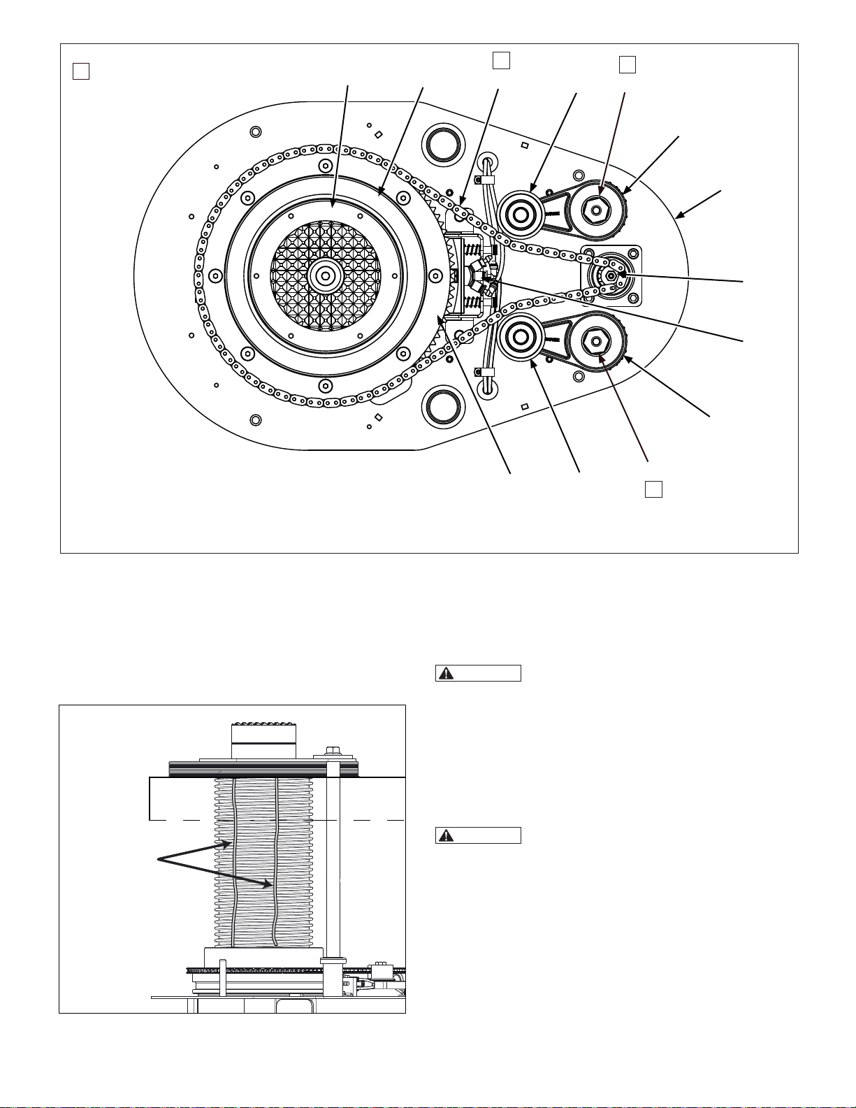
Lubricate with gear oil.
✽
(see Section 7.9 for
detailed instructions)
A
B
✽
C
D
✽
E2
E1
F
G
H
E1
Key:
A. Hydraulic Cylinder
B. Lock Nut
C. Drive Chain
D. Roller
E 1. Chain Tensioner
7. Remove any loose dirt or debris from the cylinder threads
and inspect the threads for obvious wear or damage. If the
old lubricant has dried-up, clean the threads with a brush
and some solvent before applying new lubricant.
8. Using an oil bottle with spout, apply two vertical streams
of SAE 80w-90 gear oil [ISO 150] on the exposed cylinder
threads, from top to bottom of cylinder. See Figure 19.
Apply two
streams of
gear oil to threads.
(see Section 7.9 for
detailed instructions)
Figure 19, Cylinder Thread Lubrication
E 2. Tensioner Pivot Shaft
F. Chain Drive Plate
G. Drive Sprocket
H. Proximity Sensors
I. Lock Nut Sprocket
Figure 18, Lock Nut Chain Drive Assembly
I
9. Remove the lifting sling and lower the jack front access
cover to its normal position, so it is supported by the chain
drive plate. The front access cover and protective bellows
should now completely cover the cylinder threads and chain
drive mechanism.
WARNING
installed and fully lowered before starting the jack. Never
operate the jack with the front access cover removed or
raised, either during lubrication and maintenance procedures
or when the jack is in use. Failure to observe this precaution
may result in persons becoming entangled in the moving
parts of the chain drive mechanism. Serious personal injury
could result.
10. Reconnect the air supply hose and move the air-shuto
valve to the OPEN position.
WARNING
extend and retract the cylinder several times. Stay clear of
the cylinder and related components. Keep hands and
fi ngers away from pinch and crush points. Serious personal
injury could occur if these precautions are not observed.
Refer to Section 1.3 of this manual for additional hazard
information.
11. With no load on the jack, fully extend and retract the cylinder
several times to distribute the gear oil on the cylinder
threads, and on the chain and drive components. Verify
proper operation.
12. Reinstall the jack rear access cover. Refer to Section 7.1.
Be certain that jack front access cover is
In the following step, it will be necessary to
D
E2
✽
15
Page 16

8.0 TROUBLESHOOTING
The information in the Troubleshooting Guide (refer to Table 10) is
intended as an aid to help diagnose and correct various possible
problems that may occur.
For repair service, contact your local Enerpac Authorized Service
Center. Only an Enerpac Authorized Service Center should
service the jack and its components.
Table 10 - Troubleshooting Guide
Symptom Possible Cause Solution
1. Sporadic cylinder
action and/or sluggish
operation.
a. Air trapped in hydraulic system. Cycle cylinder up and down several times to bleed trapped air.
b. Low oil level in hydraulic reservoir. Add Enerpac HF oil as required.
c. Insu cient compressed air pressure
or volume.
Check air pressure at fi lter/regulator. Increase regulator setting if pressure
shown on gauge is too low.
WARNING
Failure to observe and comply with the following precautions
could result in death or serious personal injury. Property
damage could also occur.
• Never tighten or loosen hydraulic fi ttings while jack hydraulic
system is pressurized. Escaping oil under pressure can
penetrate the skin, causing serious personal injury.
• Keep hands, fi ngers and other body parts clear of pinch
points and moving parts when observing operation during
troubleshooting.
• To prevent injury, always be sure the jack air shut-o valve
is in the CLOSED position and that the air supply hose is
disconnected before beginning any maintenance, adjustment
or repair procedures. Be certain that any trapped pressure is
completely relieved as described in Section 7.2 of this manual.
If necessary, increase volume of compressed air or increase size of supply
air line to meet airfl ow and pressure requirements.
d. Clogged or blocked pump intake
screen.
e. Pneumatic control circuit components
leaking, worn, damaged or out of
adjustment.
f. Seal wear, internal leakage, worn
components and/or other internal
damage.
2. Noisy operation. a. Air trapped in hydraulic system. Cycle cylinder up and down several times to bleed trapped air.
b. Low oil level in hydraulic reservoir. Add Enerpac HF oil as required.
c. Air mu er missing or damaged. Replace air mu er.
d. Air leaks in hydraulic system. Check all points where air might leak into system. Tighten, repair or replace
e. Clogged or blocked pump intake
screen.
f. Air motor worn or damaged. Have air motor inspected by Enerpac Authorized Service Center. Repair or
3. Oil is overheating. a. Low oil level in hydraulic reservoir. Add Enerpac HF oil as required.
b. Oil viscosity too high or too low. Drain oil from reservoir and refi ll with Enerpac HF oil.
c. Excessive cycling of cylinder. Reduce cycling of cylinder. Allow time for oil to cool between lifts.
d. Jack is overloaded. Reduce load or use a di erent jack of higher capacity.
Have hydraulic reservoir and intake screen fl ushed and cleaned by
Enerpac Authorized Service Center.
Have pneumatic control circuit inspected by Enerpac Authorized Service
Center. Repair or replace components as required.
Have hydraulic system inspected by Enerpac Authorized Service Center.
Repair or replace components as required.
components as required.
Have hydraulic reservoir and intake screen fl ushed and cleaned by
Enerpac Authorized Service Center.
replace components as required.
NOTICE: Oil may overheat if jack is overloaded, and oil runs over the relief
valve for a prolonged period of time.
e. High pressure leakage at the pump. Have hydraulic system inspected by Enerpac Authorized Service Center.
(Continued on next page)
Repair or replace components as required.
1616
Page 17

Table 10 - Troubleshooting Guide (Continued)
Symptom Possible Cause Solution
4. Motor does not run
when either pendant
button is depressed.
5. Motor starts when
pendant UP or DOWN
button is depressed,
but cylinder does not
move, or moves only a
small amount.
a. Air supply valve in the CLOSED
position.
b. Insu cient compressed air pressure. Check air pressure at fi lter/regulator. Increase regulator setting if pressure
c. Insu cient compressed air volume. If necessary, increase volume of compressed air or increase size of supply
d. Air mu er restricted by ice or debris. Check air mu er for ice or debris. Replace mu er if clogged.
e. Moisture in compressed air causing
ice formation in motor.
f. Pendant damaged. Have pendant assembly inspected by Enerpac Authorized Service Center.
g. Pneumatic control circuit components
leaking, worn, damaged or out of
adjustment.
h. Hydraulic system components
leaking, worn, damaged or out of
adjustment.
i
. Motor physically locked and/or pump
element seized.
a. Insu cient compressed air pressure
or volume.
b. Air mu er restricted by ice or debris. Check mu er for ice or debris. Replace mu er if clogged.
Move valve lever to the OPEN position. Check that fi lter/regulator gauge
indicates pressure.
shown on gauge is too low. Do not exceed 120 psi [8,3 bar].
air line to meet airfl ow and pressure requirements.
NOTICE: If pressure gauge reading drops a large amount (more than about
40 psi [2,75 bar]) when either pendant button is depressed, it is an indication
that the available compressed air volume may be too low.
Refer to step 10 of Troubleshooting chart if ice is present.
Be sure that compressed air is clean, dry and free of water.
Refer to step 10 of Troubleshooting chart if ice formation is present or
suspected.
Repair or replace components as required.
Have pneumatic control circuit inspected by Enerpac Authorized Service
Center. Repair or replace components as required.
Have hydraulic system inspected by Enerpac Authorized Service Center.
Repair or replace components as required.
Have air motor, hydraulic pump and related components inspected by
Enerpac Authorized Service Center. Repair or replace components as
required.
Check air pressure at fi lter/regulator. Increase regulator setting if pressure
shown on gauge is too low. Do not exceed 120 psi [8,3 bar].
If necessary, increase volume of compressed air or increase size of supply
air line.
NOTICE: When
pendant DOWN
button is depressed,
the cylinder will
move upward a
small amount before
retraction begins. This
is normal operation.
6. Cylinder advances
when pendant DOWN
button is depressed.
Refer to step 10 of troubleshooting if ice formation is present.
c. Jack is overloaded. Reduce load or use a di erent jack of a higher capacity.
d. Cylinder hydraulic control valve not
shifting.
e. Lock nut spin-up sensor dirty
or plugged (this symptom is applicable
to the cylinder advance circuit only).
f. Cylinder lock nut not turning. Refer to step 9 of troubleshooting.
g. Pneumatic system air line lubricator is
overfi lled.
h. Pneumatic control circuit components
leaking, worn, damaged or out of
adjustment.
i. Hydraulic system components leaking,
worn, damaged or out of adjustment.
a. Proximity-2 lock nut position sensor
dirty or plugged.
b. Pneumatic system air line lubricator
is overfi lled.
(Continued on next page)
Have control valve inspected by Enerpac Authorized Service center. Repair
or replace components as required.
NOTICE:
overrides can be used to shift the valve to test cylinder retract and extend
operation.
Have lock nut spin-up sensor checked by Enerpac Authorized Service
Center. Verify that sensor ports and air lines are not dirty or blocked.
Drain excess lubricant from air line lubricant bowl. Do not operate jack for
8 to 12 hours to allow excessive lubricant to clear from jack pneumatic
control circuit.
Have pneumatic control circuit inspected by Enerpac Authorized Service
Center. Repair or replace components as required.
Have hydraulic system inspected by Enerpac Authorized Service Center.
Repair or replace components as required.
Have Proximity-2 sensor checked by Enerpac Authorized Service Center.
Verify that sensor ports and air lines are not dirty or blocked.
Drain excess lubricant from air line lubricant bowl. Do not operate jack for 8
to 12 hours to clear excessive lubricant from jack pneumatic control circuit.
A manual override pin is located on each end of the valve. These
1717
Page 18

Table 10 - Troubleshooting Guide (Continued)
Symptom Possible Cause Solution
7. Cylinder stops
retracting when lock
nut contacts cylinder
housing. Does not fully
retract.
8. Lock nut turns too
slowly when cylinder is
retracted.
Cylinder stops part-
way and will not fully
retract.
9. Lock nut not turning. a. Cylinder threads need lubrication. Clean and lubricate cylinder threads. Refer to Section 7.9.
a. Lock nut not turning. Refer to Step 9 of troubleshooting.
b. Lock nut spin-up sensor dirty or
plugged.
c. Pneumatic system air line lubricator is
overfi lled.
d. Pneumatic control circuit components
leaking, worn, damaged or out of
adjustment.
e. Hydraulic system components
leaking, worn, damaged or out of
adjustment.
a. Lock nut not turning freely on cylinder
threads.
b. Lock nut drive train components are
worn or loose.
c. Cylinder lowering too fast. Have Enerpac Authorized Service Center inspect the counterbalance
b. Lock nut drive chain derailed, broken
or worn.
Have lock nut spin-up sensor checked by Enerpac Authorized Service
Center. Verify that sensor ports and air lines are not dirty or blocked.
Drain excess lubricant from air line lubricant bowl. Do not operate jack for 8
to 12 hours to clear excessive lubricant from jack pneumatic control circuit.
Have pneumatic control circuit inspected by Enerpac Authorized Service
Center. Repair or replace components as required.
Have hydraulic system inspected by Enerpac Authorized Service Center.
Repair or replace components as required.
Clean and lubricate cylinder threads. Refer to Section 7.9.
Have Enerpac Authorized Service Center inspect condition of lock nut drive
chain, sprockets and related components. Repair or replace components
as required.
valve and related hydraulic system components. Adjust, repair or replace
components as required.
Inspect lock nut drive chain. Reinstall or replace chain as required.
Determine if other problems may have caused drive chain wear or failure.
10. Ice formation at
pump air mu er.
or
Ice formation at lock
nut position sensors.
11. Jack is di cult to
roll on wheels.
c. Lock nut drive components are worn
or loose.
d. Lock nut position sensors dirty or
plugged.
e. Pneumatic control circuit components
leaking, worn, damaged or out of
adjustment.
f. Hydraulic system components leaking,
worn, damaged or out of adjustment.
a. Water in the air fi lter bowl. Check air fi lter bowl for water. Drain water from bowl if present.
b. Air fi lter element dirty. Clean or replace air fi lter element (inside fi lter/regulator).
c. Air line lubricator is empty. Fill lubricant bowl with anti-freeze lubricant. Refer to Section 7.6 for
d. Air line lubricator drip speed
incorrect.
e. Air supply contains excessive water. Reduce amount of water in air supply.
a. Low tire infl ation pressure. Check tire infl ation pressure. Add air if low.
b. Wheel bearings need lubrication. Apply grease to wheel bearings. See Section 7.8.
c. Wheel lock nut out of adjustment. Loosen lock nut until wheel rotates freely.
d. Caster wheel worn or stuck. Inspect caster wheel for wear and verify that it rotates and pivots freely.
Have Enerpac Authorized Service Center inspect condition of lock nut drive
chain, sprockets and related components. Repair or replace components
as required.
Check the spin-up sensor and Proximity-2 sensor. Verify that sensor ports
and air lines are not dirty or blocked. Refer to step 10 of troubleshooting if
ice has formed on or inside sensors.
Have pneumatic control circuit inspected by Enerpac Authorized Service
Center. Repair or replace components as required.
Have hydraulic system inspected by Enerpac Authorized Service Center.
Repair or replace components as required.
additional information.
Adjust the lubricator drip speed to 4 to 5 drops per minute.
Pressure should be 90 psi [6,2 bar].
Lubricate bearings with oil if necessary. Replace caster wheel if required.
18
18
Page 19
Hoja de instrucciones
POWERFUL SOLUTIONS. GLOBAL FORCE.
Pow’R-LOCK ™ Sistema de elevación portátil
Modelos de la serie PL200 (neumáticos)
L4075 Rev. B 07/14
1.0 SEGURIDAD
1.1 Introducción
Lea atentamente todas las instrucciones. Siga todas las precauciones de
seguridad recomendadas para evitar daños personales, así como daños
al gato y/o daños a otros bienes. Enerpac no puede responsabilizarse
por daños o lesiones derivados del uso inseguro del producto, falta de
mantenimiento o uso incorrecto. No quite las etiquetas, pegatinas ni
calcomanías de advertencia. Si tiene alguna pregunta o duda, póngase
en contacto con Enerpac o con algún distribuidor local de Enerpac.
Si nunca ha recibido formación sobre seguridad hidráulica de alta
presión, consulte con su distribuidor o con el centro de servicio técnico
para recibir un curso gratuito de seguridad hidráulica de Enerpac.
En este manual se emplea un sistema de símbolos de alerta de
seguridad, palabras de advertencia y mensajes de seguridad para avisar
al usuario de riesgos específi cos. El incumplimiento de las siguientes
advertencias podría causar la muerte o lesiones graves, así como daños
al equipo u otros bienes.
El Símbolo de alerta de seguridad aparece a lo largo de
este manual. Se utiliza para avisarle de posibles riesgos de
lesiones físicas. Preste especial atención a los símbolos de
alerta de seguridad y obedezca todos los mensajes de seguridad que
siguen este símbolo para evitar la posibilidad de muerte o lesiones
personales graves.
Los símbolos de alerta de seguridad se utilizan en combinación con
ciertas palabras de advertencia que llaman la atención sobre mensajes
de seguridad o mensajes de daños materiales, e indican un grado o nivel
de gravedad del riesgo. Las palabras de advertencia utilizadas en este
manual son PELIGRO, ADVERTENCIA, PRECAUCIÓN y ATENCIÓN.
PELIGRO
ADVERTENCIA
PRECAUCIÓN
ATENCIÓN
o
ATENCIÓN:
Indica una situación peligrosa que, si no se evita,
ocasionará la muerte o lesiones graves.
Indica una situación peligrosa que, de no evitarse,
puede ocasionar la muerte o lesiones graves.
Indica una situación peligrosa que, de no evitarse,
puede ocasionar lesiones menores o moderadas.
Indica información que se considera importante,
pero no relacionada con peligro (por ejemplo,
mensajes relacionados con daños materiales).
Tenga en cuenta que el símbolo de alerta de
seguridad no se utiliza en combinación con esta
palabra de advertencia.
1.2 Medidas de seguridad - Sistema de elevación portátil
Pow’R-LOCK
El incumplimiento de las siguientes precauciones de seguridad
podría ocasionar la muerte o lesiones graves. También podrían
producirse daños materiales.
• Mantenga las manos y los pies alejados del cilindro hidráulico y
sus componentes durante el funcionamiento del gato.
• Lleve siempre equipo de protección personal (PPE) al operar el
equipo hidráulico (como guantes, gafas protectoras, protección
de la cabeza, calzado de protección, etc.).
• No toque mangueras bajo presión. El aceite saliente bajo presión
puede penetrar la piel y causar lesiones graves. Consulte
inmediatamente a un médico, si se ha inyectado aceite debajo
de la piel.
• El gato debe utilizarse solo para la elevación de cargas y para
soportar cargas elevadas. Nunca utilice el gato para empujar o
separar objetos, o para otros fi nes que no estén relacionados
con la elevación.
• Nunca exceda la capacidad certifi cada del gato. Permita
un margen de seguridad que prevenga la posibilidad de
desplazamiento o desviación de la carga. El incumplimiento de
esta advertencia podría causar un fallo del gato.
• Nunca intente forzarlo con dispositivos de protección contra
sobrecarga. La válvula de alivio interna del gato solo debe ser
reparada o ajustada por un centro de servicio técnico autorizado.
La presión máxima de trabajo del sistema hidráulico del gato es
10000 psi [700 bar]. Ajustes mayores pueden provocar lesiones
personales y/o daños al equipo.
• Asegúrese de que el equipo está estable antes de levantar la
carga. Utilice el gato sobre una superfi cie sólida y nivelada,
capaz de soportar la carga y la base del gato. Coloque siempre
la carga en el centro de la silleta del gato. Si el gato no está
en posición perpendicular a la carga, esta podría deslizarse o
soltarse.
• Distribuya la carga de manera uniforme cuando efectúe
elevaciones con múltiples gatos. Si no cumple esta advertencia,
podría soltarse la carga y/o podría darse un fallo de los gatos.
• Tenga en cuenta los posibles acontecimientos externos y actos
de la naturaleza (viento, tormentas, inundaciones, terremotos
u otra actividad sísmica, etc.) que podrían ocurrir mientras el
gato está en uso, o mientras se deje cargado sin supervisión.
No utilice el gato si es probable que estas condiciones podrían
ocurrir.
19
™
ADVERTENCIA
Page 20
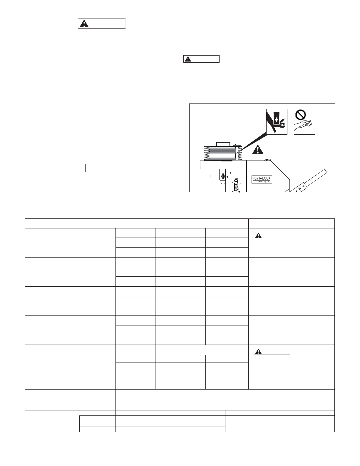
PRECAUCIÓN
El incumplimiento de las siguientes precauciones de seguridad
podría ocasionar lesiones menores o moderadas. También podrían
producirse daños materiales.
• Cuando no se utilice el gato, retraiga completamente el cilindro
y proteja toda la unidad de daños externos. Mantenga el gato
limpio, evite salpicaduras de soldaduras y guárdelo en un lugar
limpio y seco. El incumplimiento de estas precauciones puede
provocar un funcionamiento errático, menor rendimiento, mayor
desgaste y/o daño al gato.
• Mantenga el gato alejado de llamas y calor. Para un rendimiento
óptimo, no exponga el gato a temperaturas superiores a 150 ºF
[65 ºC]. El incumplimiento de estas precauciones puede provocar
un funcionamiento errático, menor rendimiento, mayor desgaste
y/o daño al gato.
• Sustituya inmediatamente las piezas desgastadas o dañadas
por piezas originales de Enerpac. Las piezas de Enerpac están
diseñadas para encajar debidamente y resistir grandes cargas.
Piezas que no sean de Enerpac pueden romperse o causar un
fallo del gato.
ATENCIÓN
• El gato no está diseñado para un soporte prolongado de objetos
elevados. Si la carga debe permanecer apoyada por más de 30 días,
utilice dispositivos de soporte de carga de una capacidad apropiada
para soportar la carga.
• El mantenimiento del equipo hidráulico solo debe ser realizado por
un técnico hidráulico cualifi cado. Comuníquese con el Centro de
Servicio Autorizado de Enerpac en su zona para prestarle servicio
de reparaciones.
1.3 Peligro de aplastamiento y machucadura
ADVERTENCIA
Nunca introduzca las manos entre la placa anti-rotación del cilindro
y la tapa de acceso delantera del gato. No toque ni introduzca las
manos en los rodillos anti-rotación. No coloque las manos en o sobre
los fuelles protectores del cilindro. Pueden producirse lesiones
personales graves si el cilindro se baja y las manos, dedos u otras
partes del cuerpo están presentes en estas áreas. Véase fi gura 1.
¡PELIGRO DE APLASTAMIENTO Y MACHUCADURA!
Peligro de aplastamiento y
machucadura
¡No introduzca las manos en
esta zona!
Figura 1, Peligro de machucadura
2.0 DATOS DEL PRODUCTO
Tabla 1 - Especifi caciones generales
Modelo Toneladas EE.UU. kN
Capacidad de carga
(Capacidad máxima)
Peso
Altura cilindro retraído
(completamente retraído)
Carrera máxima (completamente
extendido)
Presión hidráulica
Velocidad de avance de cilindro
Requisitos del aire
comprimido
ATENCIÓN: Sujeto a modifi caciones sin previo aviso.
Típico 90 - 100 psi [6,2 - 6,9 bar]
Máximo 120 psi [8,3 bar]
PL20014-ASA 200 1779
PL20025-ASA 200 1779
Modelo Libras kg
PL20014-ASA 1105 501
PL20025-ASA 1320 599
Modelo pulgadas mm
PL20014-ASA 34.0 864
PL20025-ASA 45.5 1156
Modelo pulgadas mm
PL20014-ASA 14.0 356
PL20025-ASA 24.5 622
Presión máxima de funcionamiento a
Modelo
PL20014-ASA 9898 682
PL20025-ASA 9898 682
Aproximadamente 2.0 a 2.4 pulgadas [51 - 61 mm] por minuto.
ATENCIÓN: La velocidad de avance real puede variar en función del fl ujo de aire disponible, el
ajuste del regulador de presión, la velocidad de la bomba, el peso de la carga, el diámetro de la
línea de aire entrante y otras variables.
Presión dinámica del aire Volumen del fl ujo de aire
capacidad de carga
psi bar
20
130 - 150 CFM [3681 - 4247 l/min]Mínimo 50 - 60 psi [3,4 - 4,1 bar]
(notas y precauciones)
ADVERTENCIA
capacidad de carga del gato.
Podría causar la muerte, lesiones
graves y/o daños materiales.
El peso incluye un depósito lleno de
aceite, pero no incluye accesorios,
tales como un adaptador del cilindro,
extensiones o espaciadores.
Consulte las tablas 2 y 3,
pieza E1.
Consulte las tablas 2 y 3,
pieza E2.
ADVERTENCIA
máxima del sistema hidráulico del
gato es ajustada en fábrica a
10000 psi [700 bar]. No intente
reajustar la válvula de alivio.
Podría causar la muerte, lesiones
graves y/o daños materiales.
No exceda la
La presión
Page 21
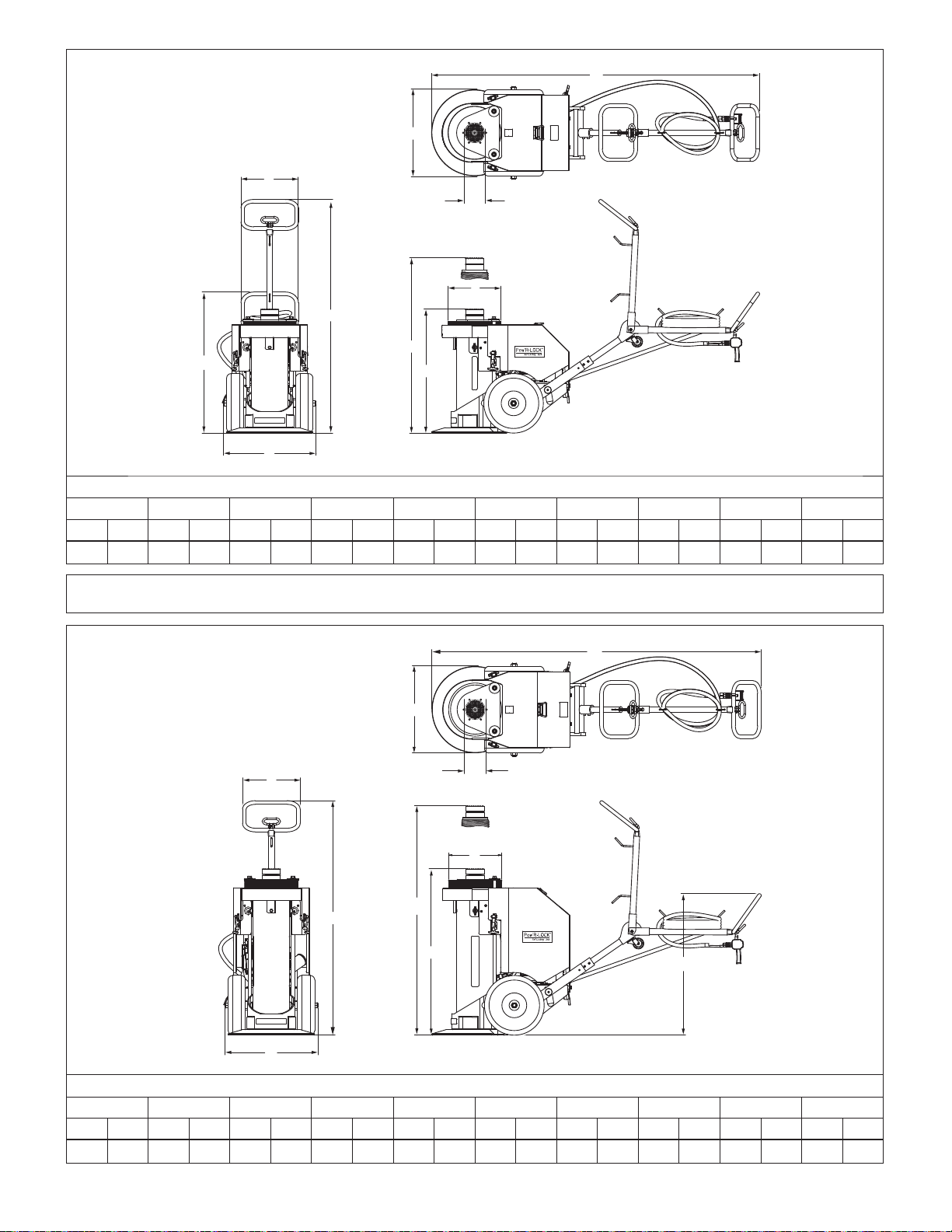
D
H
B
G
F
A2
E2
A1
C
E1
Tabla 2 - Dimensiones externas, PL20014-ASA
A1 A2 B C D E1 E2 F G H
pulgada
mm
pulgada
mm
pulgada
mm
pulgada
mm
pulgada
mm
pulgada
mm
pulgada
mm
pulgada
mm
pulgada
mm
pulgada
mm
38.6 980 64.0 1626 15.7 399 25.4 645 89.9 2283 34.0 864 48.0 1219 14.5 368 5.0 127 23.6 599
ATENCIÓN: La altura de las piezas E1 y E2 es con silleta giratoria instalada. Reste 2 pulgadas (51 mm) si se usa una silleta no giratoria.
Las dimensiones indicadas son aproximadas y sujetas a cambios sin previo aviso.
D
H
E1
G
F
A1
B
A2
E2
C
Tabla 3 - Dimensiones externas, PL20025-ASA
A1 A2 B C D E1 E2 F G H
pulgada
mm
pulgada
mm
pulgada
mm
pulgada
mm
pulgada
mm
pulgada
mm
pulgada
mm
pulgada
mm
pulgada
mm
pulgada
mm
38.6 980 64.0 1626 15.7 399 25.4 645 89.9 2283 45.5 1156 70.0 1778 14.5 368 5.0 127 23.6 599
2121
Page 22
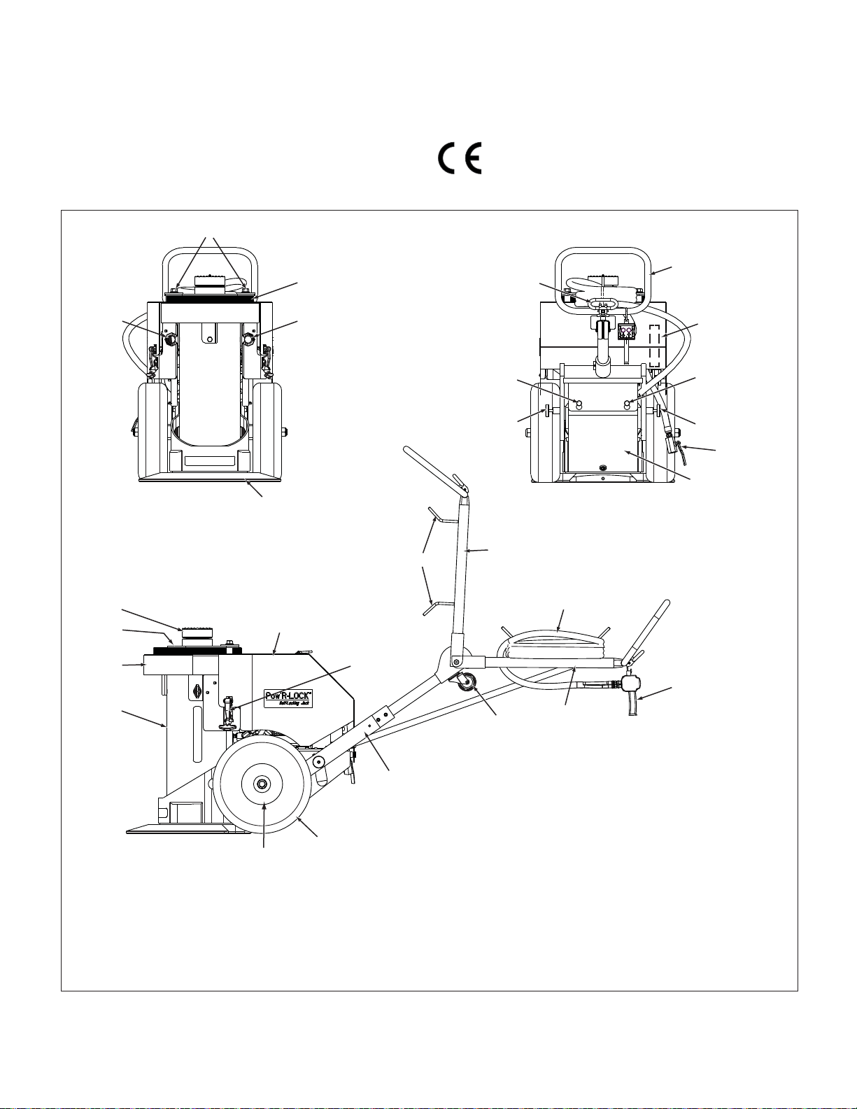
3.0 DESCRIPCIÓN DEL PRODUCTO
El gato de elevación Pow’R-LOCK ™ proporciona un bloqueo positivo
continuo de la carga durante todas las etapas de elevación y descenso.
No se requiere la intervención del operador para activar o desactivar el
sistema de bloqueo automático.
Hay disponibles dos longitudes de carrera. Ambos modelos están
equipados con un sistema de aire comprimido externo (suministrado
por el usuario). Una botonera práctica con dos botones controla el
funcionamiento del motor de aire del gato y de la válvula de control
direccional.
02
03
Consulte el párrafo 2.0 para las especifi caciones, las dimensiones y
otros datos del producto. Véase fi gura 2 para una lista de las principales
características y componentes.
4.0 CONFORMIDAD CON LAS NORMAS NACIONALES E
INTERNACIONALES
Enerpac declara que este producto ha sido probado, que
cumple con las normas aplicables y que está aprobado para
llevar la marca CE. Una declaración de conformidad UE se
adjunta por separado.
06
05
01 01
04
24
23
22
21
18
19
13
12A
16
08
09
Véase fi g. 3.
08
09
07
10
14
15
12B
11
20
17
Clave:
01. Ojillo de elevación
02. Tubos antirotación
03. Fuelles protectores
04. Base del gato
05.
Palanca de bloqueo de la manija
06. Palanca de posicionamiento
07.
Válvula de suministro de aire
08. Soportes de tapa trasera
09. Pasador de retención
10. Depósito hidráulico
11. Rueda y cubo
12A. Manija superior (levantada)
12B. Manija superior (bajada)
13.
Ganchos para recoger la manguera
14. Manguera de botonera
15. Botonera de control
16. Rueda pivotante
17. Manija inferior
18. Tapa de acceso trasera
19. Pestillo de goma
20. Neumático
21. Cilindro hidráulico
22. Tapa de acceso delantera
23. Placa antirotación
24. Silleta
Figura 2, Principales características y componentes, modelos de la serie PL200 (en la foto PL20014-ASA, PL20025-ASA similar)
22
22
Page 23
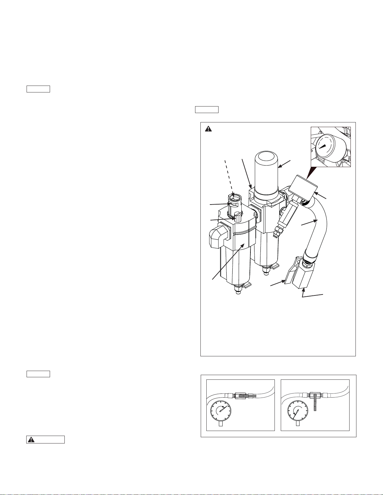
5.0 MONTAJE E INSTALACIÓN
aire está en la posición cerrada. Puede provocar una lesión grave a
los ojos y/o penetración de la piel. Si se indica alguna presión,
5.1 Importantes instrucciones de recepción
Inspeccione visualmente todos los componentes en busca de posibles
daños ocasionados durante el transporte. La garantía no cubre los
daños sufridos durante el transporte. Avise inmediatamente la empresa
transportadora en caso de que se comprueben daños de transporte.
El transportista es responsable de todos los gastos de reparación y
sustitución ocasionados por daños producidos durante el transporte.
ATENCIÓN
Debe quitar la tapa de acceso trasera del gato para acceder
a varios componentes y las piezas de servicio que se describen en los
párrafos 5.2 a 5.4. Consulte el párrafo 7.1 para las instrucciones para
retirar la tapa.
5.2 Nivel de aceite hidráulico
elimine la presión tal como se describe en el párrafo 7.2 de este
manual.
Antes de usar el gato, compruebe el nivel de lubricante en la mirilla
del lubricador para la línea de aire. Añada más lubricante si el nivel es
bajo. Consulte el párrafo 7.6 para las recomendaciones de lubricantes e
información adicional sobre el lubricador de aire.
Después de haber conectado la manguera de suministro de aire,
observe el fl ujo de aceite por la mirilla de goteo de aceite mientras el
cilindro está en movimiento. Compruebe si la velocidad de goteo del
lubricador es de 4 a 5 gotas por minuto.
ATENCIÓN
motor de aire debe estar funcionando y el cilindro debe subir y bajar.
Antes de utilizar el gato o conectar el suministro de aire, debe retirar el
tapón de llenado de aceite del depósito hidráulico y comprobar el nivel
de aceite. Añada aceite hidráulico en el depósito si el nivel del aceite
hidráulico es bajo. Consulte el párrafo 7.3. para la tabla de niveles de
aceite, especifi caciones de aceite e instrucciones adicionales.
5.3 Requisitos del aire comprimido
El sistema de aire comprimido para el gato debe ser capaz de producir
80 - 100 psi [5,5 - 6,9 bar] @ 130 CFM [3681 l/min].
El gato está equipado con un fi ltro/regulador de aire, que consiste en un
regulador de aire, manómetro y un colector de humedad. Véase fi gura
3, piezas A, B y F.
Una manguera corta conecta el fi ltro/regulador a la válvula de suministro
de aire. La conexión de entrada de aire es una rosca hembra 1/2
pulgadas NPT. Véase fi gura 3, piezas C, D y E. Consulte fi gura 4 para las
posiciones de la válvula de suministro.
Para conseguir efi ciencia en la salida de aire y un funcionamiento fi able,
se recomienda una línea de aire de alimentación con un diámetro interior
de al menos 0.82 pulgadas [20,8 mm]. (Tamaño nominal de tubo - tubo
de 3/4 pulgadas).
Compruebe el manómetro con el botón SUBIR en la botonera apretado
y el motor de aire del gato en marcha. Asegúrese de que NO haya
carga en el cilindro. Esto proporcionará una lectura exacta de la presión
dinámica del aire.
La presión dinámica mínima del aire necesaria para hacer funcionar el
gato puede variar, pero es típicamente unos 50 a 60 psi [3,4 - 4,1 bar].
Para que el gato alcance su capacidad de elevación nominal de 200
toneladas [1779 kN] se necesita una presión dinámica de aire de
aproximadamente 90 a 100 psi [6,2 a 6,9 bar].
La velocidad de elevación y par de torsión se pueden regular mediante
el botón situado encima del fi ltro/regulador. Para evitar que se dañen los
componentes del gato, el ajuste de la presión del regulador de aire no
debe exceder los 120 psi [8,3 bar].
ATENCIÓN
reducirán la vida útil del motor de aire y anularán la garantía de Enerpac
del producto.
Los ajustes de presión superiores a 120 psi [8,3 bar]
Cuando compruebe la velocidad de goteo del lubricador, el
Asegúrese de que el manómetro
(pieza B) indique cero (0) psi/bar antes
de sacar el tapón de llenado del
lubricador (pieza H).
J
I
F
A
0
B
H
C
G
E
D
Clave:
A. Botón regulador de aire
B. Manómetro
C. Manguera de suministro de aire
D. Conexión de entrada de aire
(1/2 pulgadas NPT)
E. Válvula de suministro de aire
F. Filtro/regulador de aire
(con colector de humedad)
G. Lubricador de la línea de aire
H. Tapón de llenado de lubricante
I. Mirilla de goteo de aceite
J. Control de velocidad de goteo
de aceite (en la carcasa de
goteo de aceite)
Figura 3, Filtro/regulador, lubricador de la línea
de aire y válvula de suministro de aire
5.4 Lubricación del aire
El sistema neumático del gato está equipado con un lubricador
automático para la línea de aire. Véase fi gura 3, piezas G, H, I y J. Se
necesita aire lubricado para proporcionar lubricación al motor de aire y
para prevenir la oxidación.
ADVERTENCIA
indique cero (0) psi/bar antes de retirar el tapón de llenado de
lubricante. Puede rociarse lubricante de la abertura de llenado si se
retira el tapón mientras el sistema está bajo presión, también si se
ha desconectado la manguera de aire y la válvula de suministro de
Asegúrese de que el manómetro del regulador
23
23
ABIERTA
CERRADA
Figura 4, Posiciones de válvula de suministro de aire
Page 24

5.5 Montaje de la manija superior
La manija superior se suministra sin montar. Móntela tal como se describe
en los siguientes pasos. Véase fi gura 5 para los detalles del montaje.
1.
Alinee el extremo de la manija superior con la abertura en la manija inferior.
Introduzca la manija superior en la manija inferior hasta que se detenga.
2. Fije la manija superior con dos tornillos de 3/8-16 pulgadas
(suministrados sueltos). Apriete los tornillos aproximadamente a
150 in-lbs [16,9 Nm].
3. Enrolle la manguera de la botonera holgadamente sobre los ganchos
de la manguera y cuelgue la botonera en la manija superior.
Manija
superior
4. Después de colocar el pasador de bloqueo y ambos pasadores de
retención, el gato se puede inclinar hacia atrás sobre las ruedas y
tirar o empujar hacia el área de trabajo.
PRECAUCIÓN
No camine de espaldas mientras arrastra el gato.
Mire siempre en la dirección hacia donde desplaza el gato. El no
observar esta precaución puede causar que tropiece y se caiga,
resultando en posibles lesiones personales.
Palanca de
bloqueo de
la manija
Manija
superior
Manija inferior
Tornillos
(suministrados
sueltos)
Figura 5, Montaje de la manija superior
5.6 Utilizar la manija
La manija se utiliza para transportar el gato sobre las ruedas y también
sirve para facilitar el posicionamiento del gato bajo el punto de elevación.
Véase fi gura 6 para los detalles del ajuste.
AJUSTE DE LA MANIJA SUPERIOR
Para liberar los pasadores de retención:
1. Empuje la manija superior fi rmemente hacia abajo para sacar el
2.
3. Libere lentamente la presión de mano en la manija superior hasta la
1. Empuje la palanca de bloqueo de la manija para liberar el pasador
de bloqueo.
2. Con el pasador de bloqueo liberado, posicione la manija superior
en la posición deseada. A continuación, libere la palanca de
bloqueo de la manija para que encaje el pasador de bloqueo.
• Asegúrese de que ambos pasadores de retención estén extraídos
antes de usar el gato para elevar, apoyar o descender una carga.
El no observar esta precaución puede dañar la manija inferior, las
ruedas o los ejes.
• Para posicionar el gato exactamente debajo de la carga, empuje la
PASADORES DE RETENCIÓN - MANIJA INFERIOR
Los pasadores de retención en la manija inferior deben introducirse en
los orifi cios correspondientes en el depósito hidráulico, antes de inclinar
el gato sobre las ruedas.
Para hacer encajar los pasadores de retención:
1. Asegúrese de que los pasadores de retención estén extraídos en
ambos lados de la manija inferior.
2. Empuje la manija superior fi rmemente hacia abajo. El gato se
inclinará ligeramente hacia adelante. Alinee los pasadores de
retención con los orifi cios correspondientes (situados en ambos
lados del depósito hidráulico).
3. Mientras sigue empujando la manija superior hacia abajo,
introduzca ambos pasadores de retención hasta que encajen
completamente en los orifi cios correspondientes.
manija superior hacia abajo con los pasadores de retención liberados.
5.7 Rueda pivotante
En extremo superior de la manija
superior se ha montado una rueda
pivotante. Esta rueda permite que el
gato se pueda inclinar hacia atrás y tirar
o empujar hacia el área de trabajo. La
rueda pivotante se utiliza para facilitar el
manejo del gato cuando se sitúa debajo
del punto de elevación.
Para el mejor resultado, la manija
superior debe ajustarse a la posición
más vertical posible, antes de utilizar la
rueda pivotante.
24
24
Pasador de
bloqueo
Manija inferior
Pasador de retención
(uno en cada lado
de la manija)
Figura 6, Ajustes de la manija
(botonera y manguera no mostradas)
peso de los pasadores de retención.
Saque los pasadores de retención en ambos lados de la manija inferior.
base del gato descanse en el suelo.
ATENCIÓN
Figura 7, Rueda pivotante
Page 25

5.8 Levantar y soportar el gato
En la carcasa del cilindro hay dos ojillos de elevación. Utilice estos
ojillos solo si el gato debe levantarse o soportarse por cualquier razón.
Siempre utilice un dispositivo de elevación de una capacidad adecuada.
Consulte el párrafo 2.0 para los pesos del gato.
ADVERTENCIA
gato. La manija no está diseñada para este fi n. El gato se caerá si la
manija falla. Podría causar la muerte, lesiones graves y/o daños
materiales.
Ojillo de
elevación
Nunca utilice la manija para levantar o apoyar el
Ojillo de
elevación
Figura 8, Ojillos de elevación
6.2
Antes de utilizar el gato, se debe verifi car que la superfi cie debajo del
gato es capaz de soportar la carga. El siguiente cálculo determinará la
presión máxima aproximada que ejerce el gato contra la superfi cie del
suelo, sobre la base de la carga levantada.
puede soportar de forma segura la carga a elevar, no se debe
utilizar el gato. Evite el uso del gato en caso de una sobrecarga o
con apoyos que pueden desplazarse o aplastarse bajo la carga.
Consulte a un profesional califi cado, como un ingeniero civil
licenciado o arquitecto si tiene alguna pregunta o duda sobre los
requisitos de la presión del suelo de la carga. El incumplimiento
de estas instrucciones puede causar una disposición de elevación
inestable y puede resultar en la pérdida de la carga, lesiones
personales y/o daños materiales.
CÁLCULO DE LA PRESIÓN DEL SUELO DE LA CARGA:
Peso de la carga x Factor de carga = Requisito de
• El factor de carga que debe utilizarse para el sistema imperial es 0.0125.
•
El factor de carga que debe utilizarse para el sistema métrico es 0.00194.
Cálculo de los requisitos de presión para el suelo de la carga
ADVERTENCIA
Si existe alguna duda con respecto a si el suelo
la presión del suelo
6.0 FUNCIONAMIENTO
6.1 Seguridad en la elevación
Debe conocer el peso de aquello que desea elevar y elegir un gato que
tenga una capacidad adicional de al menos un 20 por ciento.
Todas las personas que hagan uso del gato deberán adquirir y estar
familiarizados con las normas del American National Standards Institute
(Instituto Nacional Estadounidense de Normativas), o las normas
equivalentes vigentes en su país o región, que se aplican a los cilindros
y gatos hidráulicos (ASME ANSI B30.1).
ADVERTENCIA
El incumplimiento de las siguientes precauciones de seguridad
podría ocasionar la muerte o lesiones graves.
• Nunca coloque ninguna parte del cuerpo por debajo de la carga
mientras se está elevando o descendiendo. La carga podría caer
repentinamente si se vuelve inestable.
• Nunca deje el gato desatendido durante su funcionamiento,
aunque se trate de un corto período de tiempo. Vigile atentamente
el funcionamiento del gato en todo momento y esté preparado
para detener la elevación o el descenso inmediatamente. La
carga podría caerse si no se vigila durante el funcionamiento del
gato.
• No aplique fuerzas externas en la carga elevada mientras sea
soportada por el gato. La carga podría volverse inestable y caer.
• No utilice el gato en el exterior cuando haga viento. Cambios en
la dirección del viento podrían causar inestabilidad en la carga y,
en consecuencia, su caída.
• Tenga especial cuidado para mantener el nivel de la carga
cuando se efectúe la elevación con más de un gato. La mejor
manera de conseguir la nivelación adecuada, es regularla con la
válvula de suministro de aire o alternando y deteniendo los gatos
para lograr una nivelación de la carga, a fi n de que permanezca
estable y no se caiga.
• Nunca opere el gato con la tapa de acceso delantera levantada
o retirada. Pueden producirse lesiones personales graves si los
dedos, las manos u otras partes del cuerpo quedan atrapadas en
la cadena de accionamiento de la contratuerca o en las roscas
del cilindro.
Estos factores de carga son aplicables para todos los modelos de
gatos Pow’R-LOCK ™.
EJEMPLO:
Para una carga de 100000 libras [45359 kg], se aplican las siguientes
ecuaciones:
Sistema imperial: 100000 x 0.0125 = 1250 psi
Sistema métrico: 45359 x 0.00194 = 87.99 kg/cm
ATENCIÓN
limitada de carga lateral. Una carga lateral excesiva puede reducir el
soporte efectivo del gato en el suelo y aumentará la presión de contacto
del gato. Podrían dañarse los componentes del gato.
6.3 Botoneras de control
El motor de aire se pondrá en marcha automáticamente al pulsar
cualquier botón de la botonera. Véase fi gura 9.
• Para extender (subir) el cilindro pulse y mantenga apretado el botón SUBIR de la botonera.
• Para retraer (bajar) el cilindro pulse y mantenga apretado el botón BAJAR de la botonera.
• Para detener el cilindro y retener la carga suelte ambos botones de la botonera.
ATENCIÓN
una pequeña demora hasta que se produzca la acción deseada. El
circuito de control neumático del gato requiere un poco de tiempo
(hasta un segundo) para responder a los comandos de la botonera.
2
El gato está diseñado para soportar solo una cantidad
Al pulsar o soltar los botones de la botonera puede haber
BOTÓN
BAJAR
Figura 9, Controles de botonera
BOTÓN
SUBIR
25
25
Page 26

6.4 Comprobar el funcionamiento del gato antes del uso
Antes de utilizar el gato por primera vez o si el gato ha estado
almacenado durante más de 30 días, compruebe el funcionamiento del
gato tal como se describe en los siguientes pasos:
1. Si aún no lo ha hecho, compruebe el nivel de aceite en el depósito
hidráulico. Consulte el párrafo 7.3 para más información.
2. Compruebe si el gato está conectado al suministro de aire
comprimido y si el ajuste de la presión del aire es correcto.
Consulte el párrafo 5.3 para los requisitos y las recomendaciones
para la presión del aire.
3. Asegúrese de que la válvula de suministro de aire está en la
posición ABIERTA.
ATENCIÓN
párrafo 6.3 para más información sobre la botonera de control.
4. Extienda y retraiga el cilindro por completo para verifi car el
ATENCIÓN
aire está conectado y la válvula de suministro de aire está en la posición
ABIERTA. Este ruido es normal e indica que el sistema hidráulico del
gato está bajo presión.
Realice el siguiente paso sin carga en el gato. Consulte el
funcionamiento correcto. Si es necesario, haga subir y bajar el
cilindro hasta que funcione suavemente y se haya eliminado todo
el aire atrapado del sistema.
El gato hará un sonido “silbante”, cuando el suministro de
6.5 Instrucciones de funcionamiento
ADVERTENCIA
El incumplimiento de las siguientes precauciones de seguridad podría
ocasionar la muerte o lesiones graves. La carga podría volverse
inestable o caer. También podrían producirse daños materiales.
• Siempre levante, soporte y descienda la carga de acuerdo con
todas las normas de trabajo y regulaciones aplicables y vigentes
en su lugar de trabajo o centro.
• Espere durante un período de tiempo apropiado antes de
comenzar a trabajar debajo de la carga. Cualquier hundimiento
de la base del gato o de los soportes de carga (si se usan) en el
suelo no debe exceder las 1/4 pulgadas [6,4 mm]. Si se produce
un hundimiento adicional, vuelva a colocar el gato o los soportes
de carga en suelo sólido.
ANTES DE COMENZAR CON LA ELEVACIÓN:
1. Con la manija, ajuste la posición del gato para que la silleta del
cilindro esté centrada bajo el punto de elevación de la carga.
Asegúrese de que el gato está situado en una superfi cie de
soporte sólida y nivelada, con el cilindro de elevación en posición
perpendicular al suelo.
2. Después de posicionar el gato, asegúrese de que ambos pasadores
de retención en la manija inferior estén completamente extraídos
(liberados).
ATENCIÓN
extraídos antes de usar el gato para elevar, apoyar o descender una
carga. El no observar esta precaución puede dañar la manija inferior, las
ruedas o los ejes.
3. Si un punto de elevación alto requiere un gato más alto, instale
4. Coloque una pieza de contrachapado u otro tipo de material
Asegúrese de que ambos pasadores de retención estén
extensiones y /o espaciadores (accesorios opcionales) en el cilindro,
según sea necesario. Consulte el párrafo 6.6 para las instrucciones de
instalación e información adicional sobre extensiones y espaciadores.
comprimido (con un grosor de aproximadamente1/4 pulgadas
[6,4 mm], con buenas características de fricción) entre la
silleta del cilindro y el punto de elevación. Esto proporcionará
26
un poco de amortiguación y ayudará a prevenir daños al
punto de elevación.
ADVERTENCIA
podríaprovocar un desplazamiento del gato, lo que podría resultar
en una pérdida de la carga, lesiones personales y/o daños al gato.
Si es necesario, utilice una silleta giratoria para ajustar
correctamente los puntos de elevación desnivelados. La pendiente
del punto de elevación desnivelado no debe exceder los 5 grados.
PARA ELEVAR LA CARGA:
1. Pulse y mantenga apretado el botón SUBIR de la botonera. El motor
de aire se pondrá en marcha y el cilindro empezará a extenderse.
2. Cuando la carga haya alcanzado la altura deseada, suelte el
botón SUBIR de la botonera. El cilindro se detendrá y la carga
permanecerá soportada.
ATENCIÓN
funcionar como un dispositivo de soporte de cargas, puede ser que en
su ubicación se requieran soportes adicionales, dispositivos de bloqueo
u otros soportes de carga adicionales. Observe todas las normas de
trabajo y regulaciones aplicables y vigentes en su centro o lugar de
trabajo.
PARA DESCENDER LA CARGA:
ADVERTENCIA
asegúrese de que la carga desciende de manera uniforme para
evitar que esta se desplace. El desplazamiento de la carga puede
causar inestabilidad, lo cual puede resultar en la pérdida de la carga
y/o fallo del gato. Esto puede causar la muerte, lesiones graves y/o
daños materiales.
1. Asegúrese de que no haya personas trabajando debajo de la carga.
Avise a todo el personal que la carga está a punto de descender.
2. Pulse y mantenga apretado el botón BAJAR de la botonera.
El motor de aire se pondrá en marcha y el cilindro avanzará un
poco para levantar y liberar la contratuerca del cilindro. El cilindro
comenzará a retraerse.
3. Cuando la carga haya bajado la altura deseada, suelte el botón
BAJAR de la botonera. El motor de aire se parará.
DESPUÉS DE FINALIZAR EL TRABAJO:
1. Retraiga completamente el cilindro. Desconecte la manguera de
suministro de aire de la válvula de suministro de aire del gato.
2. Pulse y mantenga pulsado el botón SUBIR de la botonera para
eliminar la presión atrapada en el sistema neumático del gato.
Puede ser que el motor de aire siga funcionando unos segundos,
pero se parará cuando se haya liberado la presión.
3. Guarde el gato y sus accesorios siempre en un lugar limpio y seco, sin
humedad y sin luz solar directa.
ATENCIÓN
superior del cilindro cuando no se utilice el gato. Esto evitará la acumulación
de agua dentro de el área rebajada en la parte superior del cilindro.
6.6
Instrucciones de apilamiento – Extensiones y espaciadores
Las extensiones y los espaciadores están disponibles como accesorios
opcionales en su distribuidor autorizado de Enerpac. Consulte las
tablas 4 y 5 para información adicional.
Las extensiones de la serie PLE permiten que la altura de la elevación
útil del gato aumente en 9 pulgadas [229 mm] para el modelo PL20025ASA y hasta 28 pulgadas [711 mm] para el modelo PL20014-ASA.
Los espaciadores de la serie PLS permiten ajustes precisos adicionales
en la altura de elevación útil. Se pueden utilizar individualmente o en
combinación con las extensiones de la serie PLE. Hay disponibles
espaciadores con una altura de 1 y 2 pulgadas [25 y 51 mm].
El uso del gato en una superfi cie desnivelada
A pesar de que el gato Pow’R-LOCK ™ está diseñado para
Proceda con cuidado durante el descenso y
Mantenga siempre una silleta o extensión instalada en la parte
Page 27

▲
Usar solo con el modelo de gato PL20014-ASA.
▼
Usar con el modelo de gato PL20014-ASA o PL20025-ASA.
PLB12 PLE5 PLE7 PLE9 PLE11 PLE14
▲
▼ ▼ ▼
▲ ▲
Tabla 4 - Extensiones para las series PLB y PLE (accesorios opcionales)
Modelo de
extensión
PLB12 12 305 44.2 20,0 PLE9 9 229 28.0 12,7
PLE5 5 127 24.6 11,2 PLE11 11 279 31.7 14,4
PLE7 7 178 29.9 13,6 PLE14 14 356 37.4 17,0
ADVERTENCIA
Altura (cada una) Peso (cada una)
pulgadas mm libras kg
Modelo de
extensión
Las extensiones PLE11, PLB12 o PLE14 deben utilizarse exclusivamente con el modelo “corto” del gato PL20014-ASA.
Altura (cada una) Peso (cada una)
pulgadas
mm libras kg
El uso de estas extensiones en el modelo “alto” del gato PL20025-ASA resultará en una altura máxima de elevación excesiva. La carga
puede volverse inestable y caer, provocando posibles lesiones personales y/o daños materiales.
ATENCIÓN: Las dimensiones y los pesos mostrados son aproximados.
ADVERTENCIA
El incumplimiento de las siguientes instrucciones podría provocar
el desplazamiento o la caída de la carga y puede resultar en una
lesión personal y/o daños materiales.
• Utilice solo extensiones y espaciadores auténticos de Enerpac
de la serie PLB, PLE y PLS con el gato Pow’R-LOCK ™. Nunca
utilice extensiones o espaciadores que se hayan fabricado o
precauciones y condiciones puede causar una disposición de
elevación inestable. La carga puede desplazarse o caer y provocar
lesiones personales y/o daños materiales.
Siga las siguientes reglas, precauciones y condiciones cuando utilice
extensiones y espaciadores de la serie PLB, PLE y PLS.
• En la tabla 6 se indica la altura adicional máxima de apilamiento
diseñado para el uso en otro dispositivo de elevación.
• Nunca exceda la altura adicional máxima de apilamiento
establecida para el modelo de su gato. Consulte la tabla 6 para
• La altura total de los espaciadores de la serie PLS instalados en el
más información. Una altura de apilamiento excesiva reducirá la
estabilidad del gato.
• Modelo de gato PL20014-ASA: En el bloque puede haber solo una
ADVERTENCIA
(dimensión “X”) permita. Al instalar las extensiones y los espaciadores,
no exceda las dimensiones establecidas para su modelo de gato.
bloque no debe exceder las 2 pulgadas [51 mm].
El incumplimiento de las siguientes reglas,
extensión base PLB12 (si se utiliza) y la PLB12 siempre debe estar
situada en el fondo del apilamiento. No intente apilar dos o más
PLB12 una encima de la otra.
• Las extensiones PLE11, PLB12 y PLE14 están diseñadas para ser
utilizadas únicamente con el modelo PL20014-ASA. Para evitar una
PLS1
PLS2
operación peligrosa, no utilice estas extensiones en el modelo de
gato PL20025-ASA (véase la declaración de advertencia al pie de la
Tabla 5 - Espaciadores de la serie PLS
(accesorios opcionales)
Modelo de espaciador
Altura (cada uno)
pulgadas
mm libras kg
Peso (cada uno)
Tabla 4).
• Tenga especial cuidado para evitar cargas descentradas y cargas
laterales al utilizar extensiones y espaciadores.
ATENCIÓN:
PLS1 1.0 25 4.5 2,0
PLS2 2.0 51 9.1 4,1
Las dimensiones y los pesos mostrados son aproximados.
27
Page 28

Tabla 6 - Altura adicional de apilamiento máxima
(Utilizando extensiones de la serie PLB y PLE
y espaciadores de la serie PLS opcionales)
Altura adicional
de apilamiento
Modelo de gato
máxima
(dimensión “X”)
pulgadas
mm
alineados con los pasadores de soporte de la tapa en la parte
trasera del depósito hidráulico.
PL20014-ASA 28.0 711
PL20025-ASA 9.0 229
Altura de apilamiento (dimensión “X”) incluye la altura total combinada de
todas las extensiones y espaciadores instalados. La altura de la silleta NO está
incluida en la altura de apilamiento.
X
6.7 Silletas
Una silleta giratoria viene incluida con el gato como parte del equipo.
Hay una silleta no giratoria disponible como accesorio opcional, que se
utiliza para aplicaciones donde se requiere una altura retraída pequeña.
Consulte el párrafo 7 para los números de modelo de las silletas.
ATENCIÓN
Utilice una silleta giratoria para ajustar correctamente los
puntos de elevación desnivelados. La silleta giratoria deberá utilizarse
siempre que el desalineamiento entre la silleta estándar y el punto de
elevación sea tan grande que no pueda compensarse solo con el uso de
una madera contrachapada u otro material comprimido adecuado.
3. Retire la tapa con cuidado hacia atrás hasta que se hayan
4. Invierta los pasos 1, 2 y 3 para volver a montar la cubierta. En las
antes de utilizar el gato. A no ser que sea necesario para los
procedimientos de mantenimiento, no opere el gato con la tapa
retirada. Pueden producirse lesiones personales graves si personas
entran en contacto con superfi cies calientes o con líneas o
componentes bajo presión mientras la tapa está retirada. También
podrían producirse daños si caen objetos sobre los componentes
expuestos.
Figura 10, Sacar la tapa de acceso trasera
desbloqueado los pasadores y levante entonces la tapa del gato.
aberturas del chavetero, asegúrese de que la ranura de cada pasador
de soporte de la tapa esté alineada con la cubierta de chapa metálica
antes de montar completamente la tapa sobre el gato.
ADVERTENCIA
Siempre monte la tapa de acceso trasera del gato
DD4880045SR PLC1
Tabla 7 - Silletas
Altura
Modelo de silleta
DD4880045SR
Silleta giratoria (de serie)
PLC1
Silleta no giratoria (accesorio
opcional)
ATENCIÓN: Las dimensiones y los pesos mostrados son aproximados.
(cada una)
pulgadas
3.3 84 20.2 9,2
0,88 22 10.4 4,7
mm libras kg
Peso
(cada una)
7.0 MANTENIMIENTO
7.1 Sacar la tapa de acceso trasera
Debe quitar la tapa de acceso trasera del gato para acceder a varios
puntos de inspección, lubricación y mantenimiento. Retire la tapa de
acceso trasera del gato tal como se describe en los siguientes pasos:
1. Desenganche los pestillos de goma en ambos lados de la tapa.
2. Levante la tapa hasta que los orifi cios redondos de la tapa estén
28
7.2
Despresurizar los sistemas hidráulicos y neumáticos del gato
Para ciertos procedimientos de mantenimiento que se describen en
el párrafo 7 de este manual, se requiere que los sistemas hidráulicos
y neumáticos del gato estén despresurizados antes de empezar el
procedimiento. Estas operaciones son necesarias para garantizar la
seguridad del personal de mantenimiento.
ADVERTENCIA
El incumplimiento de los procedimientos en los
siguientes pasos podría ocasionar un arranque inesperado del gato
mientras se lleva a cabo el mantenimiento y la reparación. Una
liberación incontrolada de la presión también puede ocurrir si se
abren componentes o se afl ojan conexiones bajo presión. Podrían
producirse lesiones graves.
ATENCIÓN
El sistema hidráulico debe despresurizarse primero, antes
despresurizar el sistema neumático. Asegúrese siempre de despresurizar
ambos sistemas.
1. Despresurice el sistema hidráulico del gato, tal como se describe
en los pasos 1a hasta 1c:
a. Compruebe si el gato está conectado al suministro de aire y la
válvula de suministro de aire está en la posición ABIERTA.
b. Asegúrese de que el cilindro está en la posición totalmente retraída.
c.
Pulse el botón SUBIR en la botonera mientras observa el cilindro.
Suelte el botón SUBIR INMEDIATAMENTE cuando el cilindro comienza a
avanzar (generalmente después de 1 o 2 segundos). Este procedimiento
eliminará la presión atrapada en el sistema hidráulico del gato.
Page 29

ATENCIÓN
Para evitar que se acumule presión hidráulica en el sistema,
no pulse el botón BAJAR de la botonera en cualquier momento durante
los siguientes pasos.
2. Despresurice el sistema neumático del gato, tal como se describe
en los pasos 2a hasta 2f:
a. Ponga la válvula de suministro de aire en la posición CERRADA.
b. Desconecte la manguera de suministro de aire de la válvula de
suministro de aire del gato.
ATENCIÓN
En el siguiente paso, el gato puede arrancar y funcionar
brevemente, al expulsar aire atrapado del sistema neumático del gato.
c. Pulse y mantenga apretado el botón SUBIR de la botonera.
Mantenga el botón apretado hasta que el motor de aire del gato
deje de funcionar. El motor generalmente se parará después de
aproximadamente 2 a 6 segundos, dependiendo de la longitud de
la manguera de suministro de aire.
d. Verifi que si el gato no hace un “silbido” audible.
e. Retire la tapa de acceso trasera del gato (si no la ha retirado
antes). Consulte el párrafo 7.1.
f. Compruebe el manómetro de aire en el fi ltro/lubricador del gato.
Verifi que si indica cero (0) psi/bar.
ATENCIÓN
Si el manómetro indica presión, asegúrese de que la válvula
de suministro de aire está en la posición CERRADA y que la manguera
de aire está desconectada de la válvula de suministro de aire. A
continuación, repita los pasos 2c hasta 2f.
Continúe con el procedimiento de mantenimiento o reparación deseado.
3.
7.3 Comprobar el Nivel de aceite
Compruebe el nivel de aceite hidráulico cada 90 días.
1. Asegúrese de que el cilindro esté completamente retraído y el gato
esté situado en una superfi cie sólida y nivelada.
2. Retire la tapa de acceso trasera del gato. Consulte el párrafo 7.1.
3. Asegúrese de que la válvula de suministro de aire está en la
posición CERRADA.
4. Desenrosque y retire el tapón de llenado de aceite. Véase fi gura 11.
5. Compruebe el nivel de aceite en el depósito. El nivel de aceite debe
encontrarse aproximadamente a 1 pulgada [25 mm] de la parte
superior del depósito, con el cilindro completamente retraído y el
motor apagado. Véase fi gura 11.
6. Si el nivel de aceite es bajo, añada aceite hidráulico HF de Enerpac,
según sea necesario. Utilice un embudo para evitar goteos.
ATENCIÓN
• El depósito tiene un conducto de ventilación. No llene el depósito
completamente hasta el borde, para evitar que rebose aceite del
conducto de ventilación.
• Para evitar que el depósito se sobrellene accidentalmente, asegúrese
siempre de que el cilindro esté completamente retraído antes de
comprobar el nivel de aceite o añadir aceite adicional.
• Si Enerpac HF no está disponible en el lugar de trabajo, utilice un
aceite hidráulico equivalente que cumpla con las especifi caciones
que se muestran en la tabla 8.
7. Vuelva a colocar el tapón de llenado de aceite.
Vuelva a montar la tapa de acceso trasera del gato. Consulte el párrafo 7.1.
8.
Tabla 8 - Especifi caciones del aceite hidráulico - ISO 32
Grado ISO 32
Índice de viscosidad 100 min
Viscosidad a 210
Viscosidad a 100 °F
Viscosidad a 0
Gravedad API 31.0-33.0
Infl amación,C.O.C.
Punto de fl uidez,
°F
°F
°F
°F
42-45 S.U.S.
150-165 S.U.S.
<12000 S.U.S.
400
-35
29
Tapón de
llenado de
aceite
Nivel de
aceite
(LLENO)
LLENO = 1 pulgada [25 mm]
debajo del borde superior del depósito
Figura 11, Nivel de aceite - Depósito hidráulico
(manija retirada para mostrar los detalles)
ATENCIÓN
• El no utilizar el aceite adecuado podría provocar daños en los
componentes hidráulicos del gato e invalidar la garantía del producto.
Se recomienda enérgicamente el uso del aceite HF de Enerpac.
• Asegúrese de que el aceite está limpio. La limpieza del aceite debe
mantenerse a un nivel máximo de 18/16/13 de conformidad con la norma
ISO4406. Si el aceite tiene una apariencia oscura, nebulosa o lechosa,
debe cambiarse de inmediato, tal como se describe en el párrafo 7.4.
7.4 Cambiar el aceite
Cambie el aceite en el depósito hidráulico cada 12 meses o 500 horas
de funcionamiento. Véase fi gura 12.
Las condiciones expuestas a continuación requerirán cambios de aceite
más frecuentes:
• Un funcionamiento bajo circunstancias pesadas, en las que la
temperatura del aceite alcance los 150º F [60° C].
• Cuando haya un alto grado de humedad en el entorno y/o cambios
de temperatura extremos que puedan provocar la condensación del
aceite dentro del depósito.
• Cuando haya un entorno sucio o polvoriento que pueda contaminar
el aceite.
Cambie el aceite como se describe en los siguientes pasos:
1. Asegúrese de que el cilindro esté completamente retraído.
2. Retire la tapa de acceso trasera del gato. Consulte el párrafo 7.1.
3. Libere completamente toda la presión atrapada en el sistema
hidráulico y neumático del gato. Desconecte la manguera de
suministro de aire de la válvula de suministro de aire. Siga el
procedimiento en el párrafo 7.2.
ATENCIÓN
[18,9 litros] de aceite cuando se llena hasta el nivel adecuado con el
cilindro completamente retraído y el motor de aire apagado. Elimine el
aceite usado de acuerdo con la legislación y normas aplicables.
4. Afl oje y retire el tapón de drenaje del aceite de la parte inferior
5. Limpie y vuelva a colocar el tapón de drenaje de aceite.
El depósito hidráulico contiene aproximadamente 5 galones
del depósito. Deje que el aceite usado se vacíe en un recipiente
adecuado. Puede ser necesario inclinar el gato ligeramente hacia
atrás para drenar completamente todo el aceite y los residuos del
fondo del depósito.
Page 30

6. Retire, limpie y vuelva a colocar el conducto de ventilación del
depósito. Cambie el conducto de ventilación del depósito si está
obstruido o dañado.
7. Con una llave de correa, afl oje y retire el fi ltro de aceite viejo. Recoja
todo el aceite vertido en un recipiente adecuado. Elimine el aceite
vertido de acuerdo con todas las legislaciones y normas aplicables.
ATENCIÓN
Utilice solo un fi ltro de aceite nuevo de 10 micras con las
especifi caciones adecuadas (No. de artículo de Enerpac 69670E o equivalente).
8. Antes de la instalación, lubrique la junta de goma del fi ltro de aceite
nuevo con un poco de aceite. Apriete el fi ltro a mano (no utilice
herramientas).
4
1
2.
Clave:
1. Conducto de ventilación
2. Tapón de llenado de aceite
Figura 12, Cambio de aceite (manija retirada para mostrar los detalles)
9. Retire el tapón de llenado de aceite y añada aceite hidráulico HF
de Enerpac, según sea necesario. Utilice un embudo para evitar
goteos. El nivel de aceite debe encontrarse aproximadamente a 1
Vista trasera
3.
3. Tapón de drenaje de aceite
4. Filtro de aceite
F
G
Asegúrese de que el
manómetro (pieza B) indique
cero (0) psi/bar antes de sacar el
tapón de llenado del lubricador
(pieza H) o realizar actividades
de mantenimiento.
pulgada [25 mm] de la parte superior del depósito, con el cilindro
completamente retraído y el motor apagado. Véase fi gura 11 para
la tabla de niveles de aceite.
ATENCIÓN
• El depósito tiene un conducto de ventilación. No llene el depósito
completamente hasta el borde, para evitar que rebose aceite del
conducto de ventilación.
• Para evitar que el depósito se sobrellene accidentalmente, asegúrese
siempre de que el cilindro esté completamente retraído antes de
comprobar el nivel de aceite o añadir aceite adicional.
• Si Enerpac HF no está disponible en el lugar de trabajo, utilice un
aceite hidráulico equivalente que cumpla con las especifi caciones
que se muestran en la tabla 8.
10. Limpie el tapón de llenado de aceite y aplique un sellador de rosca
en las roscas. Vuelva a colocar el tapón de llenado de aceite.
ADVERTENCIA
cilindro varias veces. Manténgase alejado del cilindro y los
componentes relacionados. Mantenga las manos y los dedos alejados
de los puntos de machucadura y aplastamiento. El incumplimiento de
estas precauciones podría causar lesiones graves. Consulte el párrafo
1.3 de este manual para más información sobre peligros.
11. Sin carga en el gato, extienda y retraiga el cilindro varias veces
para comprobar su correcto funcionamiento y para eliminar el aire
atrapado en el sistema hidráulico.
12. Con el cilindro completamente retraído y el motor de la bomba
apagado, vuelva a comprobar el nivel de aceite para asegurarse de
que no ha bajado. Añada más aceite si es necesario. Véase fi gura
11 para la tabla de niveles de aceite.
13.
Vuelva a montar la tapa de acceso trasera del gato. Consulte el párrafo 7.1.
7.5 Filtro/regulador para línea de aire (véase la fi gura 13)
Cada 30 horas de funcionamiento:
1. Retire la tapa de acceso trasera del gato. Consulte el párrafo 7.1.
2. Libere completamente toda la presión atrapada en el sistema
hidráulico y neumático del gato. Desconecte la manguera de
suministro de aire de la válvula de suministro de aire. Siga el
procedimiento en el párrafo 7.2.
En el siguiente paso, debe extender y retraer el
J
A
B
I
H
K
Clave:
A. Botón regulador de aire
B. Manómetro
C. Manguera de suministro de aire
D. Conexión de entrada de aire
(1/2 pulgadas NPT)
E. Válvula de suministro de aire
Figura 13, Elementos de servicio y de mantenimiento de rutina - Filtro/regulador de aire y lubricador de línea de aire
M
L
F. Filtro/regulador de aire
(con colector de humedad)
G. Lubricador de la línea de aire
H. Tapón de llenado de lubricante
I. Mirilla de goteo de aceite
J. Control de velocidad de goteo de aceite
N
K. Mirilla del recipiente del fi ltro
L. Válvulas de drenaje
M. Mirilla del recipiente de lubricante
N. Recipiente de lubricante
O. Recipiente del fi ltro
30
Vista frontal
O
C
E
D
Page 31

3. Compruebe si hay agua en la mirilla del recipiente del fi ltro. En el
fondo del recipiente del fi ltro/regulador hay un drenaje manual.
Si hay agua, drénela en un recipiente adecuado y elimine el agua
de acuerdo con todas las legislaciones y normas aplicables.
Asegúrese de que el drenaje esté completamente cerrado después
de fi nalizar el drenaje.
4. Retire el recipiente del fi ltro e inspeccione el elemento del fi ltro de
aire (en el interior del recipiente del fi ltro). Cambie el elemento del
fi ltro si está sucio.
ATENCIÓN
contacto con Norgren para instrucciones detalladas sobre el
mantenimiento, los elementos fi ltrantes y las piezas de repuesto.
El fi ltro/regulador es fabricado por Norgren. Póngase en
7.7 Silenciador de
Cada 30 horas de funcionamiento:
1. Retire la tapa de acceso trasera del gato. Consulte el párrafo 7.1.
2.
3. Inspeccione el silenciador de escape de aire. Elimine toda la
4. Si el silenciador viejo está muy sucio u obstruido, reemplace el
7.6 Lubricador para línea de aire (véase la fi gura 13)
Cada 30 horas de funcionamiento:
1. Retire la tapa de acceso trasera del gato. Consulte el párrafo 7.1.
2. Compruebe la mirilla en el recipiente de lubricante para la línea de
aire. El nivel de lubricante debe estar al menos 1/2 lleno.
ATENCIÓN
como se describe en los pasos 3 hasta 6. Si el nivel de lubricante es
correcto, salte estos pasos y preceda con el paso 7.
3. Libere completamente toda la presión atrapada en el sistema
presión del sistema neumático del gato y de que el manómetro del
regulador indique cero (0) psi/bar antes de retirar el tapón de
llenado de lubricante. Puede rociarse lubricante de la abertura de
llenado si se retira el tapón mientras el sistema está bajo presión,
también si se ha desconectado la manguera de aire y la válvula de
suministro de aire está en la posición cerrada. Puede provocar una
lesión grave a los ojos y/o penetración de la piel.
4. Retire el tapón de llenado de lubricante. Añada más lubricante si es
Para temperaturas ambiente superiores a 32°F [0°C], utilice un
ATENCIÓN
en la mirilla. No utilice el gato con una cantidad excesiva de
lubricante en el recipiente de lubricante. Si se llena en exceso el
recipiente de lubricante, el circuito lógico de aire del gato puede
inundarse con lubricante e impedir el funcionamiento normal del
gato.
5. Vuelva a colocar el tapón de llenado de lubricante.
6. Vuelva conectar la manguera de suministro de aire. Asegúrese de
7. Compruebe la velocidad de goteo en la mirilla.
• La velocidad de goteo debe ser de 4 a 5 gotas por minuto.
• Si la velocidad de goteo es demasiado baja o alta, reajústela según
ATENCIÓN
Póngase en contacto con Norgren para instrucciones detalladas sobre
el mantenimiento, los elementos fi ltrantes y las piezas de repuesto.
8.
Si el nivel de lubricante es bajo, añada más lubricante tal
hidráulico y neumático del gato. Desconecte la manguera de
suministro de aire de la válvula de suministro de aire. Siga el
procedimiento en el párrafo 7.2.
ADVERTENCIA
necesario, hasta que el nivel llegue a la parte superior de la mirilla
de lubricante. ¡NO SOBREPASE EL NIVEL!
lubricante para herramientas neumáticas de alta calidad SAE
10 [ISO 32]. Para temperaturas ambiente inferiores a 32°F [0°C],
utilice solo un lubricante para herramientas neumáticas con un
anticongelante a base de glicol (número de artículo de Enerpac
DD5142835 o equivalente).
que la válvula de suministro de aire está en la posición ABIERTA.
Compruebe siempre la velocidad de goteo mientras el cilindro
avanza o retrocede.
sea necesario. Use un destornillador de punta plana para girar el
tornillo de ajuste de la velocidad de goteo.
Vuelva a montar la tapa de acceso trasera del gato. Consulte el párrafo 7.1.
Asegúrese de que se haya eliminado toda la
El nivel del lubricante no debe exceder el nivel máximo
El lubricador para la línea de aire es fabricado por Norgren.
31
7.8 Ruedas y neumáticos (véase la fi gura 15)
Cada 30 horas de funcionamiento:
• Compruebe si los neumáticos están desgastados o dañados.
• Compruebe la presión de aire de los neumáticos. Cada neumático
Cada 12 meses:
• En cada cubo de rueda hay un lubricador. Lubrique los dos cojinetes
• Compruebe si la rueda pivotante está dañada y si gira libremente.
escape de aire (véase la fi gura 14)
Desconecte la manguera de suministro de aire de la válvula de
suministro de aire. Libere completamente toda la presión atrapada en
el sistema neumático del gato. Siga el procedimiento en el párrafo 7.2.
suciedad o residuos.
silenciador por uno nuevo. Utilice solo un silenciador de escape
de aire de 25 micras con las especifi caciones originales (No. de
artículo de Enerpac DD4791116 o equivalente).
Silenciador de
escape de aire
Figura 14, Silenciador de escape de aire
Cámbielos si es necesario.
debe tener una presión de hasta 90 psi [6,2 bar].
de las ruedas con una grasa para cojinetes de ruedas de alta calidad.
Limpie toda la suciedad suelta y lubrique los cojinetes con aceite.
Consulte la fi gura 7 en el párrafo 5.7 de este manual.
Lubricador de
cojinetes de ruedas
Válvula de aire
del neumático
Figura 15, Ruedas y neumáticos
Page 32

7.9 Lubricar las roscas del cilindro y la cadena de
accionamiento de la contratuerca (véanse las fi guras 16-19)
Las roscas del cilindro y la cadena de accionamiento de la contratuerca
deben lubricarse aproximadamente cada 30 horas de funcionamiento.
Ambas actividades de lubricación se pueden realizar al mismo tiempo,
como se describe en los siguientes pasos:
1. Asegúrese de que no haya carga en el gato.
2. Desenganche los pestillos de goma y retire la tapa de acceso
trasera del gato. Véase párrafo 7.1. para el procedimiento.
ATENCIÓN
debe estar completamente extendido y el sistema neumático del gato
debe estar sin presión. Siga las instrucciones en los pasos 3a-3f.
3. Extienda completamente el cilindro y despresurice el sistema
a. Pulse y mantenga apretado el botón SUBIR de la botonera para
b. Ponga la válvula de suministro de aire en la posición CERRADA.
c. Desconecte la manguera de suministro de aire de la válvula de
ATENCIÓN
brevemente, al expulsar aire atrapado del sistema neumático del gato.
d. Pulse y mantenga apretado el botón SUBIR o BAJAR de la
e. Verifi que si el gato no hace un “silbido” audible.
f. Compruebe el manómetro de aire en el fi ltro/lubricador del gato.
NOTICE
de suministro de aire está en la posición CERRADA y que la manguera
de aire está desconectada de la válvula de suministro de aire. A
continuación, repita los pasos 2d hasta 2f.
esté desconectada y que el manómetro del regulador indique cero (0)
psi/bar antes de Continúar con este procedimiento. El gato se pondrá
en marcha inmediatamente cuando el manómetro indique presión y se
pulse en cualquier botón de la botonera. La contratuerca y la cadena
empezarán a girar. Si el gato se pone en marcha mientras se realizan
procedimientos de lubricación pueden producirse lesiones graves.
4. Retire la tapa de acceso delantera del gato de modo que las roscas
Antes de realizar los procedimientos de lubricación, el cilindro
neumático del gato:
hacer subir el cilindro. Siga manteniendo el botón apretado hasta
que el cilindro esté completamente extendido y el motor de aire del
gato deje de funcionar. Véase fi gura 16.
suministro de aire.
En el siguiente paso, el gato puede arrancar y funcionar
botonera. Mantenga el botón apretado hasta que el motor de
aire del gato deje de funcionar. El motor generalmente se parará
después de aproximadamente 2 a 6 segundos, dependiendo de la
longitud de la manguera de suministro de aire.
Verifi que si indica cero (0) psi/bar.
Si el manómetro indica presión, asegúrese de que la válvula
ADVERTENCIA
Asegúrese de que la manguera de suministro de aire
del cilindro estén máximamente expuestas. Véase fi gura 17.
Figura 17, Levantar la tapa de acceso trasera para mostrar las roscas
5. Fije una eslinga de elevación a la cubierta de acceso delantera.
Envuelva la eslinga alrededor de la placa anti-rotación y la silleta,
de modo que la cubierta se mantenga en la posición elevada.
Asegúrese de que la eslinga sea lo sufi cientemente fuerte para
soportar el peso de la cubierta (aproximadamente 15 libras [5,6
kg]) y de que quede bien sujeta.
6. Lleve a cabo las siguientes tareas de inspección y lubricación.
Véase fi gura 18.
• Elimine toda la suciedad o residuos de la transmisión de cadena.
• Compruebe cada tensor de la cadena para verifi car si el muelle
ejerce sufi ciente tensión contra la cadena. Si el tensor no se
mueve libremente o si la tensión del muelle es débil, debe ser
reemplazado. Los tensores no se pueden ajustar o reparar.
• Compruebe si en los rodillos tensores hay indicaciones evidentes
de desgaste o daños. Cambie los rodillos si es necesario. Los
rodillos se venden por separado como pieza de repuesto.
• Compruebe todos los dientes en los piñones de la contratuerca
y de transmisión para ver si hay indicaciones evidentes de
desgaste o daños. Cambie estas piezas si es necesario.
ATENCIÓN
Consulte la tabla 9 para las especifi caciones del aceite para
engranajes.
• Aplique una capa fi na de aceite para engranajes SAE 80w-90
[ISO 150] en las conexiones de la cadena de accionamiento de
la contratuerca.
• En cada tensor, aplique un poco de aceite para engranajes 80w-
90 [ISO 68] en las áreas expuestas del casquillo del eje pivotante
del tensor, situado debajo de la tuerca de retención del tensor.
Una parte del aceite fl uirá por el casquillo y en el eje pivotante del
tensor. No es necesario sacar la tuerca.
Figura 16, Extensión completa del cilindro
Tabla 9 - Especifi caciones del aceite de engranajes - SAE
80w-90 [ISO 150]
(Para lubricar las roscas del cilindro, la cadena de accionamiento de
la contratuerca, los piñones y el eje pivotante del tensor.)
Grado SAE
Grado ISO
Índice de viscosidad 103
Viscosidad a 40
Viscosidad a 100
Punto de infl amación,
Punto de fl uidez,
ATENCIÓN: Las especifi caciones mostradas en esta tabla son típicas. Las
especifi caciones exactas pueden diferir, dependiendo de la marca de aceite.
32
°C, cSt
°cSt
°C
°F
80w-90
150
136
14.5
202
-30
Page 33

Lubrique con aceite de engranajes.
✽
(véase párrafo 7.9 para
instrucciones detalladas)
A
B
✽
C
D
✽
E2
E1
F
G
H
E1
Clave:
A. Cilindro hidráulico
B. Contratuerca
C. Cadena de accionamiento
D. Rodillo
E 1. Tensor de cadena
7. Elimine toda la suciedad o residuos de las roscas del cilindro e
inspeccione las roscas para ver si hay indicaciones evidentes de
desgaste o daños. Si el lubricante viejo se ha secado, limpie las
roscas con un cepillo y un poco de disolvente antes de aplicar el
nuevo lubricante.
8. Con una botella de aceite con vertedor, aplique dos líneas
verticales de aceite para engranajes SAE 80w-90 [ISO 150] en las
roscas expuestas del cilindro, de arriba a abajo del cilindro. Véase
fi gura 19.
Aplique dos
líneas de aceite
de engranaje en
las roscas
(Véase párrafo 7.9
para instrucciones
detalladas)
Figura 19, Lubricación de la rosca del cilindro
E 2. Eje pivotante de tensor
F. Placa de cadena de accionamiento
G. Piñón de accionamiento
H. Sensores de proximidad
I. Piñón de contratuerca
Figura 18, Cadena de accionamiento de contratuerca
33
I
9. Retire la eslinga de elevación y baje la tapa de acceso delantera del
gato a su posición normal, de forma que es apoyada por la placa
de la cadena de accionamiento. Ahora, la tapa de acceso delantera
y los fuelles protectores deben cubrir completamente las roscas
del cilindro y el mecanismo de la cadena de accionamiento.
ADVERTENCIA
gato esté montada y completamente bajada antes de poner en
marcha el gato. Nunca opere el gato con la tapa de acceso delantera
retirada o levantada, ya sea durante los procedimientos de
lubricación y mantenimiento o cuando el gato está en uso. Si no se
observa esta precaución, pueden quedar personas atrapadas en
las partes móviles del mecanismo de la cadena de accionamiento.
Podrían producirse lesiones graves.
10. Vuelva a conectar la manguera de suministro de aire y ponga la
válvula de suministro de aire en la posición ABIERTA.
ADVERTENCIA
cilindro varias veces. Manténgase alejado del cilindro y los
componentes relacionados. Mantenga las manos y los dedos
alejados de los puntos de machucadura y aplastamiento. El
incumplimiento de estas precauciones podría causar lesiones
graves. Consulte el párrafo 1.3 de este manual para más información
sobre peligros.
11. Sin carga en el gato, extienda y retraiga el cilindro varias veces para
distribuir el aceite de engranajes sobre las roscas del cilindro, en
la cadena y en los componentes de accionamiento. Compruebe si
funciona correctamente.
12. Vuelva a montar la tapa de acceso trasera del gato. Consulte el
párrafo 7.1.
Asegúrese de que la tapa de acceso delantera del
En el siguiente paso, debe extender y retraer el
D
E2
✽
Page 34

8.0 SOLUCIÓN DE PROBLEMAS
La información en la Guía de solución de problemas (consulte la tabla
10) está diseñada como ayuda al diagnóstico y la corrección de los
distintos posibles problemas.
Para obtener servicio de reparación, contacte con su Centro de Servicio
Autorizado de Enerpac. Solo un Centro de Servicio Autorizado de
Enerpac puede reparar el gato y sus componentes.
Tabla 10 - Guía de solución de problemas
Síntoma Posible causa Solución
1. Acción esporádica del
cilindro y/o funcionamiento
difi cultoso.
a. Hay aire retenido en el sistema hidráulico. Haga subir y bajar el cilindro varias veces para liberar el aire retenido.
b. Nivel bajo de aceite en el depósito
hidráulico.
c. Volumen o presión de aire comprimido
insufi ciente.
El incumplimiento de las siguientes precauciones de seguridad
podría ocasionar la muerte o lesiones graves. También podrían
producirse daños materiales.
• No apriete ni afl oje las conexiones hidráulicas cuando el sistema
• Cuando observe el funcionamiento durante la solución de problemas,
• Para evitar lesiones, siempre asegúrese de que la válvula de suministro
Añada aceite HF de Enerpac según se necesite.
Compruebe la presión de aire en el fi ltro/regulador. Suba el ajuste del regulador si la
presión indicada en el manómetro es demasiado baja.
ADVERTENCIA
hidráulico del gato esté presurizado. El aceite saliente bajo presión
puede penetrar la piel y causar lesiones graves.
mantenga las manos, los dedos y otras partes del cuerpo alejados de
puntos de machucadura y piezas móviles.
de aire del gato está en la posición CERRADA y que la manguera de
suministro de aire está desconectada, antes de comenzar cualquier
procedimiento de mantenimiento, ajuste o reparación. Asegúrese de
toda la presión atrapada está completamente liberada tal como se
describe en el párrafo 7.2 de este manual.
Si es necesario, aumente la cantidad de aire comprimido o el tamaño de la línea de
suministro de aire para cumplir los requisitos de presión y de fl ujo de aire.
d. Rejilla de entrada de aire de la bomba
obstruida o bloqueada.
e. Componentes del circuito neumático con
fugas, desgastados, dañados o fuera de ajuste.
f. Juntas desgastadas, fugas internas,
componentes desgastados y/u otros daños
internos.
2. Funcionamiento con ruido. a. Hay aire retenido en el sistema hidráulico. Haga subir y bajar el cilindro varias veces para liberar el aire retenido.
b. Nivel bajo de aceite en el depósito
hidráulico.
c. Silenciador de escape de aire falta o está
dañado.
d. Hay fugas de aire en el sistema hidráulico. Compruebe todos los puntos por los que pueda entrar aire en el sistema. Apriete, repare
e. Rejilla de entrada de aire de la bomba
obstruida o bloqueada.
f. Motor de aire desgastado o dañado. Solicite la inspección del motor de aire en un Centro de Servicio Autorizado de Enerpac.
3. Sobrecalentamiento del
aceite.
a. Nivel bajo de aceite en el depósito hidráulico. Añada aceite HF de Enerpac según se necesite.
b. Viscosidad del aceite demasiado alta o
demasiado baja.
c. Funcionamiento excesivo del cilindro. Reduzca el funcionamiento del cilindro. Deje que el aceite se enfríe entre las
d. Gato sobrecargado. Reduzca la carga o utilice un gato de mayor capacidad.
Solicite el vaciado y la limpieza del depósito hidráulico y la rejilla de entrada de aire en
un Centro de Servicio Autorizado de Enerpac.
Solicite la inspección del circuito neumático en un Centro de Servicio Autorizado de
Enerpac. Repare o sustituya los componentes según sea necesario.
Solicite la inspección del sistema hidráulico en un Centro de Servicio Autorizado de
Enerpac. Repare o sustituya los componentes según sea necesario.
Añada aceite HF de Enerpac según se necesite.
Sustituya el silenciador de escape de aire.
o sustituya los componentes según sea necesario.
Solicite el vaciado y la limpieza del depósito hidráulico y la rejilla de entrada de aire en
un Centro de Servicio Autorizado de Enerpac.
Repare o sustituya los componentes según sea necesario.
Drene y rellene el depósito con aceite HF de Enerpac.
elevaciones.
ATENCIÓN: El aceite puede calentarse excesivamente si el gato está sobrecargado, y
si el aceite se extiende sobre la válvula de alivio por un período prolongado de tiempo.
e. Fugas de alta presión en la bomba. Solicite la inspección del sistema hidráulico en un Centro de Servicio Autorizado de
(Continúa en la siguiente página)
Enerpac. Repare o sustituya los componentes según sea necesario.
3434
Page 35

Tabla 10 - Guía de solución de problemas (continuación)
Síntoma Posible causa Solución
4. El motor no funciona al
pulsar cualquier botón de
la botonera.
5. El motor arranca al pulsar
el botón SUBIR o BAJAR
en la botonera, pero el
cilindro no se mueve, o se
mueve solo un poco.
a. Válvula de suministro de aire está en la
posición CERRADA.
b. Presión de aire comprimido insufi ciente. Compruebe la presión de aire en el fi ltro/regulador. Suba el ajuste del regulador si la
c. Volumen de aire comprimido insufi ciente. Si es necesario, aumente la cantidad de aire comprimido o el tamaño de la línea de
d. El silenciador de escape de aire está
obstruido por hielo o suciedad.
e. Hay humedad en el aire comprimido que
causa la formación de hielo en el motor.
f. Botonera dañada. Solicite la inspección de la botonera en un Centro de Servicio Autorizado de Enerpac.
g. Componentes del circuito neumático con
fugas, desgastados, dañados o fuera de ajuste.
h. Componentes del sistema hidráulico con
fugas, desgastados, dañados o fuera de ajuste.
i
. Motor físicamente bloqueado y/o elemento
de bomba agarrotado.
a. Volumen o presión de aire comprimido
insufi ciente.
b. El silenciador de escape de aire está
obstruido por hielo o suciedad.
Ponga la palanca de la válvula en la posición ABIERTA. Compruebe si la mirilla del
fi ltro/regulador indica presión.
presión indicada en el manómetro es demasiado baja. No exceda los 120 psi [8,3 bar].
suministro de aire para cumplir los requisitos de presión y fl ujo de aire.
ATENCIÓN: Si la lectura del manómetro baja mucho (más de aproximadamente 40 psi
[2,75 bar]), al pulsar cualquier botón de la botonera, es una indicación de que el volumen
de aire comprimido disponible es demasiado bajo.
Compruebe si el silenciador de escape de aire está obstruido por hielo o suciedad.
Cambie el silenciador de escape de aire si está obstruido.
Si hay hielo, consulte el paso 10 de la tabla Solución de problemas.
Asegúrese de que el aire comprimido está limpio, seco y que no contiene
agua.
Si hay o se sospecha formación de hielo, consulte el paso 10 de la tabla Solución de
problemas.
Repare o sustituya los componentes según sea necesario.
Solicite la inspección del circuito neumático en un Centro de Servicio Autorizado de
Enerpac. Repare o sustituya los componentes según sea necesario.
Solicite la inspección del sistema hidráulico en un Centro de Servicio Autorizado de
Enerpac. Repare o sustituya los componentes según sea necesario.
Solicite la inspección del motor de aire, bomba hidráulica y componentes relacionados
en un Centro de Servicio Autorizado de Enerpac. Repare o sustituya los componentes
según sea necesario.
Compruebe la presión de aire en el fi ltro/regulador. Suba el ajuste del regulador si la
presión indicada en el manómetro es demasiado baja. No exceda los 120 psi [8,3 bar].
Si es necesario, aumente la cantidad de aire comprimido o el tamaño de la línea de
suministro de aire.
Compruebe si hay hielo o suciedad en el silenciador de escape de aire. Cambie el
silenciador de escape de aire si está obstruido.
ATENCIÓN: Al pulsar
el botón BAJAR en la
botonera, el cilindro
subirá un poco antes
de comenzar la
retracción. Esto es un
movimiento normal.
6. El cilindro avanza al pulsar
el botón BAJAR de la
botonera.
Si hay formación de hielo, consulte el paso 10 de la tabla Solución de problemas.
c. Gato sobrecargado. Reduzca la carga o utilice un gato de mayor capacidad.
d. La válvula de control del sistema hidráulico
del cilindro no cambia de posición.
e. Sensor de giro de la contratuerca sucio u
obstruido (este síntoma solo es aplicable al
circuito de avance del cilindro).
f. La contratuerca del cilindro no gira. Consulte el paso 9 de la Solución de problemas.
g. El lubricador de la línea de aire del sistema
neumático está demasiado lleno.
h. Componentes del circuito neumático con
fugas, desgastados, dañados o fuera de ajuste.
i. Componentes del sistema hidráulico con
fugas, desgastados, dañados o fuera de ajuste.
a. Sensor de posición Proximity-2 de la
contratuerca sucio u obstruido.
b. El lubricador de la línea de aire del sistema
neumático está demasiado lleno.
(Continúa en la siguiente página)
Solicite la inspección de la válvula de control en un Centro de Servicio Autorizado de
Enerpac. Repare o sustituya los componentes según sea necesario.
ATENCIÓN: En ambos extremos de la válvula hay un accionador manual. Estos
accionadores pueden utilizarse para mover la válvula y comprobar el funcionamiento de
retracción y extensión del cilindro.
Solicite la inspección del sensor de giro de la contratuerca en un Centro de Servicio
Autorizado de Enerpac. Compruebe si los puertos y las líneas de aire del sensor están
sucios u obstruidos.
Drene el lubricante excesivo del recipiente de lubricante para la línea de aire. No opere
el gato durante 8 a 12 horas para que pueda salir el lubricante excesivo del circuito
neumático del gato.
Solicite la inspección del circuito neumático en un Centro de Servicio Autorizado de
Enerpac. Repare o sustituya los componentes según sea necesario.
Solicite la inspección del sistema hidráulico en un Centro de Servicio Autorizado de
Enerpac. Repare o sustituya los componentes según sea necesario.
Solicite la inspección del sensor Proximity-2 en un Centro de Servicio Autorizado
de Enerpac. Compruebe si los puertos y las líneas de aire del sensor están sucios u
obstruidos.
Drene el lubricante excesivo del recipiente de lubricante para la línea de aire. No opere
el gato durante 8 a 12 horas para que pueda salir el lubricante excesivo del circuito
neumático del gato.
3535
Page 36

Tabla 10 - Guía de solución de problemas (continuación)
Síntoma Posible causa Solución
7. El cilindro se detiene en el
movimiento de retracción
cuando la contratuerca
toca la carcasa del
cilindro. No se retrae
completamente.
8. La contratuerca gira
demasiado despacio
cuando el cilindro está
retraído.
El cilindro se detiene a
medio camino y no se
retrae completamente.
9. La contratuerca no gira. a. Las roscas del cilindro deben lubricarse. Limpie y lubrique las roscas del cilindro. Consulte el párrafo 7.9.
a. La contratuerca no gira. Consulte el paso 9 de la Solución de problemas.
b. Sensor de giro de la contratuerca sucio u
obstruido.
c. El lubricador de la línea de aire del sistema
neumático está demasiado lleno.
d. Componentes del circuito neumático con
fugas, desgastados, dañados o fuera de ajuste.
e. Componentes del sistema hidráulico con
fugas, desgastados, dañados o fuera de ajuste.
a. La contratuerca no gira libremente sobre las
roscas del cilindro.
b. Componentes del accionamiento de la
contratuerca están desgastados o sueltos.
c. Descenso del cilindro demasiado rápido. Solicite la inspección de la válvula de contrapeso y los componentes hidráulicos
b. Cadena de accionamiento de la contratuerca
descarrilada, rota o desgastada.
Solicite la inspección del sensor de giro de la contratuerca en un Centro de Servicio
Autorizado de Enerpac. Compruebe si los puertos y las líneas de aire del sensor están
sucios u obstruidos.
Drene el lubricante excesivo del recipiente de lubricante para la línea de aire. No opere
el gato durante 8 a 12 horas para que pueda salir el lubricante excesivo del circuito
neumático del gato.
Solicite la inspección del circuito neumático en un Centro de Servicio Autorizado de
Enerpac. Repare o sustituya los componentes según sea necesario.
Solicite la inspección del sistema hidráulico en un Centro de Servicio Autorizado de
Enerpac. Repare o sustituya los componentes según sea necesario.
Limpie y lubrique las roscas del cilindro. Consulte el párrafo 7.9.
Solicite la inspección de la cadena de accionamiento de la contratuerca, los piñones y
los componentes relacionados en un Centro de Servicio Autorizado de Enerpac. Repare
o sustituya los componentes según sea necesario.
relacionados en un Centro de Servicio Autorizado de Enerpac. Ajuste, repare o
sustituya los componentes según sea necesario.
Inspeccione la cadena de accionamiento de la contratuerca. Vuelva a instalar o sustituya
la cadena según sea necesario. Determine si otros problemas pudieran causar el
desgaste o fallo de la cadena de accionamiento.
10. Formación de hielo en
el silenciador de escape
de aire de la bomba.
o
Formación de hielo en
los sensores de posición
de la contratuerca.
11. El gato rueda con
difi cultad sobre las
ruedas.
c. Componentes del accionamiento de la
contratuerca están desgastados o sueltos.
d. Sensores de posición de la contratuerca
sucios u obstruidos.
e. Componentes del circuito neumático con
fugas, desgastados, dañados o fuera de ajuste.
f. Componentes del sistema hidráulico con
fugas, desgastados, dañados o fuera de ajuste.
a. Agua en el recipiente del fi ltro de aire. Compruebe si hay agua en el recipiente del fi ltro de aire. Si hay agua, drénela.
b. Elemento del fi ltro de aire sucio. Limpie o cambie el elemento del fi ltro de aire (dentro del fi ltro/regulador).
c. El lubricador de la línea de aire está vacío. Llene el recipiente de lubricante con lubricante anticongelante. Consulte el párrafo 7.6
d. Velocidad de goteo del lubricador de la línea
de aire incorrecta.
e. Suministro de aire contiene demasiada agua. Reduzca la cantidad de agua en el suministro de aire.
a. Neumáticos con presión de aire baja. Compruebe la presión de aire de los neumáticos. Añada más aire si la presión es baja.
a. Los cojinetes de las ruedas deben lubricarse. Aplique grasa en los cojinetes de las ruedas. Véase párrafo 7.8.
d. Contratuerca de la rueda fuera de ajuste. Afl oje la contratuerca hasta que las ruedas giren libremente.
d. Rueda pivotante desgastada o dañada. Compruebe si la rueda pivotante está desgastada y verifi que si la rueda gira y rueda
Solicite la inspección de la cadena de accionamiento de la contratuerca, los piñones y
los componentes relacionados en un Centro de Servicio Autorizado de Enerpac. Repare
o sustituya los componentes según sea necesario.
Compruebe el sensor de giro y el sensor Proximity-2. Compruebe si los puertos y las
líneas de aire del sensor están sucios u obstruidos. Si se ha formado hielo sobre o en los
sensores, consulte el paso 10 de Solución de problemas.
Solicite la inspección del circuito neumático en un Centro de Servicio Autorizado de
Enerpac. Repare o sustituya los componentes según sea necesario.
Solicite la inspección del sistema hidráulico en un Centro de Servicio Autorizado de
Enerpac. Repare o sustituya los componentes según sea necesario.
para más información.
Ajuste la velocidad de goteo del lubricador a 4 a 5 gotas por minuto.
La presión debe ser 90 psi [6,2 bar].
libremente.
Lubrique los cojinetes con aceite si es necesario. Cambie la rueda pivotante si es
necesario.
36
36
Page 37

Folha de Instruções
POWERFUL SOLUTIONS. GLOBAL FORCE.
Pow’R-LOCK ™ Sistema Portátil de Levantamento
Modelos da Série PL200 (acionamento pneumático)
L4075 Rev. B 07/14
1.0 SEGURANÇA
1.1 Introdução
Leia cuidadosamente todas as instruções. Siga todos os avisos de
segurança para evitar lesões pessoais, assim como danos ao macaco
e/ou a outras propriedades. A Enerpac não pode ser responsabilizada
por danos ou lesões pessoais resultantes do uso indevido, falta
de manutenção ou operação incorreta. Não remova os rótulos de
advertência, etiquetas ou decalques. Caso surjam perguntas ou
preocupações, entre em contato com a Enerpac ou com um distribuidor
local da Enerpac para esclarecimentos.
Caso não tenha recebido treinamento sobre segurança na hidráulica
de alta pressão, consulte seu distribuidor ou centro de serviço para um
Curso gratuito da Enerpac sobre Hidráulica de Alta Pressão.
Este manual segue um sistema de símbolos de alerta de segurança,
palavras de sinalização e mensagens de segurança para avisar
ao usuário sobre perigos específi cos. O não cumprimento destas
advertências pode resultar em morte ou sérias lesões pessoais, assim
como danos ao equipamento ou a outras propriedades.
O Símbolo de Alerta de Segurança aparece em todo este
manual. É usado para alertá-lo sobre potenciais perigos de
danos físicos. Preste muita atenção aos Símbolos de Alerta
de Segurança e obedeça a todas as mensagens de segurança que
acompanham este símbolo para evitar a possibilidade de morte ou
sérias lesões pessoais.
Os Símbolos de Alerta de Segurança são utilizados em conjunto com
certas Palavras de Sinalização que chamam atenção para mensagens
de segurança ou de danos materiais e designam um grau ou nível da
seriedade do perigo. As Palavras de Sinalização usadas neste manual
são PERIGO, ADVERTÊNCIA, PRECAUÇÃO e AVISO.
PERIGO
ADVERTÊNCIA
PRECAUÇÃO
AVISO
ou
AVISO
Indica uma situação perigosa que, se não for
evitada, resultará em morte ou graves lesões
pessoais.
Indica uma situação perigosa que, se não for
evitada, poderá resultar em morte ou graves lesões
pessoais.
Indica uma situação perigosa que, se não for
evitada, poderá resultar em lesões pessoais
menores ou moderadas.
Indica informações consideradas importantes,
mas não relacionadas ao perigo (por exemplo,
mensagens relacionadas com danos materiais).
Por favor, observe que os Símbolos de Alerta de
Segurança não serão usados com esta palavra de
sinalização.
1.2 Precauções de Segurança - Pow'R-LOCK ™ Sistema
Portátil de Levantamento
A inobservância em cumprir as seguintes precauções pode
resultar em morte ou graves lesões pessoais. Podem ocorrer
danos materiais.
• Mantenha mãos e pés distantes do cilindro hidráulico e
• Use sempre equipamentos de proteção individual (EPI) quando
• Não manuseie mangueiras pressurizadas. Sob pressão, o
• O macaco deve ser usado somente para levantar cargas e
• Nunca exceda a capacidade nominal do macaco. Permita uma
• Nunca interfi ra nos dispositivos de proteção contra sobrecarga.
• Certifi que-se de que o arranjo para o levantamento esteja estável
• Distribua a carga uniformemente ao executar levantamentos
• Informe-se sobre acontecimentos externos ou atos da
37
ADVERTÊNCIA
componentes relacionados durante a operação de levantamento.
acionar equipamento hidráulico (tais como luvas, proteção para
os olhos, proteção para a cabeça, calçados de proteção etc).
vazamento de óleo pode penetrar na pele, causando graves
lesões pessoais. Se o óleo penetrar na pele, procure um médico
imediatamente.
suportar as cargas levantadas. Nunca use o macaco para
empurrar ou separar objetos, ou para outros objetivos não
relacionados ao levantamento.
margem de segurança que responda por possíveis condições
de cargas deslocadas ou cargas laterais. A inobservância desta
advertência pode causar falha do macaco.
A válvula interna de alívio do macaco não deve ser consertada
ou ajustada exceto por um centro autorizado de serviços. A
máxima pressão hidráulica nominal do sistema hidráulico de
levantamento é de 700 bar [10.000 psi]. Ajustes mais altos podem
resultar em lesões pessoais e/ou danos ao equipamento.
antes de levantar a carga. Somente use o macaco em uma
superfície sólida e estável, capaz de suportar a carga e a base do
macaco. Centralize sempre a carga na assento do macaco. Se o
macaco não estiver perpendicular em relação à carga, é possível
que ocorram escorregões ou perda da carga.
com vários macacos. Falta de atenção a esta advertência pode
causar perda da carga e/ou falha dos macacos.
natureza (vento, tempestade, inundações, terremotos ou outras
atividades sísmicas etc.) que podem ocorrer, tanto enquanto
o macaco estiver em uso, ou quando for deixado carregado e
desacompanhado. Não utilize o macaco se houver possibilidade
de ocorrência destas condições.
Page 38

PRECAUÇÃO
Deixar de observar e cumprir as seguintes precauções pode resultar
em lesões pessoais menores ou moderadas. Podem ocorrer danos
materiais.
• Quando o macaco não estiver em uso, recolha totalmente o
cilindro e proteja toda a unidade de danos externos. Mantenha
o macaco limpo, evite respingos de solda e guarde-o em área
limpa e seca. A inobservância destas precauções pode causar
operação irregular, menor desempenho, maior desgaste e/ou
danos ao macaco.
• Mantenha o macaco longe de chamas e calor. Para um
desempenho ideal, não exponha o macaco a temperaturas
acima de 65ºC [150°F]. A inobservância destas precauções pode
causar operação irregular, menor desempenho, maior desgaste
e/ou danos ao macaco.
• Substitua imediatamente as peças gastas ou danifi cadas por
peças originais Enerpac. As peças da Enerpac são projetadas
para se encaixar adequadamente e resistir a cargas altas.
Peças que não sejam Enerpac podem quebrar ou causar o mal
funcionamento do macaco.
AVISO
• O macaco não é projetado para apoio de objetos levantados por um período
longo. Caso a carga deva ser mantida apoiada por mais de 30 dias, use
dispositivos apropriadamente dimensionados para suportar a carga.
• A manutenção de equipamento hidráulico deve ser executada somente
por técnico qualifi cado em hidráulica. Para serviços de reparo, entre
em contato com o Centro Autorizado de Serviço em sua área.
1.3 Ponto de Perigo de Esmagamento e Aperto
ADVERTÊNCIA
APERTO! Nunca entre em contato com a placa antirrotacional do
cilindro e com a tampa frontal de acesso do macaco. Não toque ou
agarre as hastes antirrotacionais. Não coloque as mãos no cilindro
ou nos foles de proteção do cilindro. Graves lesões pessoais podem
ocorrer se o cilindro for baixado e mãos, dedos ou outras partes do
corpo estiverem nestas áreas. Veja a Fig. 1.
PONTO DE PERIGO DE ESMAGAMENTO E
Ponto de Perigo de Aperto e
Esmagamento
Não se aproxime desta área!
Figura 1, Ponto de Perigo de Aperto
2.0 DADOS DO PRODUTO
Tabela 1 - Especifi cações Gerais (notas e precauções)
Modelo kN
Capacidade Nominal da Carga
(Capacidade Máxima)
Peso
Altura fechada (totalmente retraído)
Curso Máximo (totalmente
estendido)
Pressão Hidráulica
Velocidade de Avanço do Cilindro
Requisitos para o Ar
Comprimido
AVISO: As especifi cações estão sujeitas a modifi cação sem aviso prévio.
Típico 6,2 - 6,9 bar [90 - 100 psi]
Máximo 8,3 bar [120 psi]
PL20014-ASA 1779 200
PL20025-ASA 1779 200
Modelo kg Libras
PL20014-ASA 501 1105
PL20025-ASA 599 1320
Modelo mm polegadas
PL20014-ASA 864 34,0
PL20025-ASA 1156 45,5
Modelo mm polegadas
PL20014-ASA 356 14,0
PL20025-ASA 622 24,5
Pressão Máx. de Trabalho na
Modelo
PL20014-ASA 682 9898
PL20025-ASA 682 9898
Aproximadamente 51 – 61 mm [2,0 a 2,4" NPT] por minuto.
AVISO: A velocidade de avanço real vai variar dependendo da vazão de ar, ajuste do regulador de pressão,
velocidade da bomba, peso da carga, diâmetro da linha de entrada de alimentação e outras variáveis.
Pressão Pneumática Dinâmica Volume de Vazão Pneumática
Capacidade Nominal da Carga
bar psi
38
Toneladas Americanas
3681 - 4247 l/min [130 - 150 CFM]Mínimo 3,4 - 4,1 bar [50 - 60 psi]
ADVERTÊNCIA
capacidade nominal de força. Pode
resultar em morte, graves lesões
pessoais e/ou danos materiais.
O peso inclui o reservatório
abastecido com óleo, mas não inclui
acessórios como adaptadores do
cilindro, extensões e espaçadores.
Veja as tabelas 2 e 3,
item E1.
Veja as tabelas 2 e 3,
item E2.
ADVERTÊNCIA
do sistema do macaco hidráulico vem
ajustada de fábrica para 700 bar
[10000 psi]. Não tente reajustar a
pressão da válvula de alívio. Pode
resultar em morte, graves lesões
pessoais e/ou danos materiais.
Não exceda a
A pressão máxima
Page 39

D
H
B
G
F
A2
E2
A1
C
E1
Tabela 2 - Dimensões Externas, PL20014-ASA
A1 A2 B C D E1 E2 F G H
mm
polegadammpolegadammpolegadammpolegadammpolegadammpolegadammpolegadammpolegadammpolegadammpolegada
980 38,6 1626 64,0 399 15,7 645 25,4 2283 89,9 864 34,0 1219 48,0 368 14,5 127 5,0 599 23,6
AVISO: A altura dos itens E1 e E2 é com o assento oscilante instalado. Subtraia 51 mm (2 polegadas) se o assento oscilante não for utilizado.
As dimensões mostradas são aproximadas e estão sujeitas à modifi cações sem aviso prévio.
D
H
E1
G
F
A1
B
A2
C
E2
Tabela 3 - Dimensões Externas, PL20025-ASA
A1 A2 B C D E1 E2 F G H
mm
polegadammpolegadammpolegadammpolegadammpolegadammpolegadammpolegadammpolegadammpolegadammpolegada
980 38,6 1626 64,0 399 15,7 645 25,4 2283 89,9 1156 45,5 1778 70,0 368 14,5 127 5,0 599 23,6
3939
Page 40

3.0 DESCRIÇÃO DO PRODUTO
O macaco de levantamento Pow’R-LOCK ™ oferece travamento positivo
contínuo da carga através de todos os estágios dos movimentos de
levantamento e descida. Sem necessidade de intervenção do operador
para ativar ou desativar o sistema de travamento automático.
Veja a Seção 2.0 para as especifi cações, dimensões e outros detalhes
do produto. Veja a Figura 2 para uma lista das principais características
e componentes.
4.0 DE ACORDO COM OS PADRÕES NACIONAIS E
Dois comprimentos diferentes de curso estão disponíveis. Ambos
os modelos são acionados por uma rede externa de ar comprimido
(fornecida pelo usuário). Um conveniente controle remoto de dois
botões comanda a operação pneumática do motor e a válvula de
controle direcional.
02
03
incluída separadamente.
INTERNACIONAIS.
A Enerpac declara que este produto foi testado, está de
acordo com os padrões aplicáveis e aprovado para ter a
marca da C.E. Uma Declaração de Conformidade da UE está
06
05
01 01
04
24
23
22
21
18
19
13
12A
16
08
09
Veja a Fig. 3.
08
09
07
10
14
15
12B
11
20
17
Legenda:
01. Olhal de Levantamento
02. Tubos antirrotacionais
03. Foles de Proteção
04. Base do Macaco
05. Trava do Punho da Alavanca
06. Posicionando a Alavanca
07. Válvula de Bloqueio de Ar
08. Apoios da Tampa Posterior
09. Pino de Detenção
10. Reservatório Hidráulico
11. Roda e Cubo
12A. Alavanca Superior (levantada)
12B. Alavanca Superior (abaixada)
13. Ganchos de Armazenamento
de Mangueira
14. Mangueira do controle
15. Controle
16. Rodízio
17. Alavanca Inferior
18. Tampa de Acesso Posterior
19. Trava de Borracha
20. Pneu
21. Cilindro Hidráulico
22. Tampa de Acesso Dianteira
23. Placa antirrotacional
24. Assento
Figura 2, Principais Características e Componentes, Modelos da Série PL200 (PL20014-ASA mostrada, PL20025-ASA similar)
40
40
Page 41

5.0 MONTAGEM E CONFIGURAÇÃO
e/ou penetração na pele. Caso haja indicação de qualquer pressão,
alivie a pressão, conforme descrito na Seção 7.2 deste manual.
5.1 Instruções importantes para o recebimento
Inspecione visualmente todos os componentes quanto à avarias durante
o transporte. Avarias no transporte não são cobertas pela garantia.
Caso haja avarias no transporte, avise o transportador imediatamente.
O transportador é responsável por todos os custos de consertos e
substituições decorrentes de avarias ocorridas no transporte.
AVISO
A tampa traseira de acesso do macaco deve ser removida
para conseguir acesso a diversos componentes e itens de manutenção
discutidos nas seções 5.2 até 5.4. Veja a Seção 7.1 para instruções de
remoção da tampa.
5.2 Nível do Óleo Hidráulico
Antes de usar o macaco, verifi que o nível do lubrifi cante no indicador
de nível no lubrifi cador da linha de ar. Adicione lubrifi cante se estiver
baixo Veja a Seção 7.6 para as recomendações de lubrifi cação do ar e
informações adicionais sobre o lubrifi cador de ar.
Depois que a mangueira de suprimento de ar for conectada, observe
a vazão de óleo através da janela de gotejamento enquanto o cilindro
estiver em movimento. Verifi que se a velocidade de gotejamento do
lubrifi cador é de 4 a 5 gotas por minuto.
AVISO
movendo para cima ou para baixo quando a velocidade de gotejamento
de óleo do lubrifi cador for verifi cada.
Antes de usar o macaco ou fazer a ligação ao suprimento de ar, remova
o bujão de abastecimento de óleo do reservatório hidráulico e verifi que
o nível de óleo. Adicione mais óleo hidráulico ao reservatório se o nível
de óleo estiver baixo. Veja a Seção 7.3 para o diagrama de nível de óleo,
especifi cações de óleo e instruções adicionais.
5.3 Requisitos para o Ar Comprimido
O sistema de ar comprimido usado com o macaco deve ser capaz de
fornecer 5,5 - 6,9 bar [80 - 100 psi] @ 3681 l/min [130 CFM].
O macaco é equipado com um conjunto de fi ltro de ar/regulador,
que consiste em um regulador de ar, manômetro de pressão e um
reservatório de condensados. Veja a Figura 3, itens A, B e F.
Uma mangueira curta conecta o fi ltro/regulador com a válvula de
bloqueio de ar. A conexão de entrada de ar tem roscas fêmeas de
1/2" NPT. Veja a Figura 3, itens C, D e E. Consulte a Figura 4 para as
posições da válvula de bloqueio.
Para uma vazão efi ciente e operação confi ável, recomenda-se uma
linha de suprimento de ar de não menos que 20,8 mm [0,82" NPT] de
diâmetro interno. (Tamanho Nominal do Tubo – tubo de 3/4" NPT).
Verifi que o manômetro de pressão de ar com o botão UP (para cima)
pressionado e com o motor pneumático do macaco funcionando.
Certifi que-se de que NÃO há carga no cilindro. Isto dará a leitura precisa
da pressão pneumática dinâmica.
A pressão pneumática dinâmica mínima necessária para acionar o
macaco varia, mas, tipicamente, é de cerca de 3,4 – 4,1 bar [50 a 60 psi].
Aproximadamente de 6,2 a 6,9 bar [90 a 100 psi] de pressão pneumática
dinâmica serão necessários para que o macaco atinja sua capacidade
de levantamento de 1779kN [200 ton].
A velocidade de levantamento e o torque podem ser ajustados usando
o botão de ajuste localizado na parte superior do fi ltro/regulador. Para
evitar danos aos componentes pneumáticos do macaco, o ajuste do
regulador de pressão pneumática não deve exceder 8,3 bar [120psi].
AVISO
vida reduzida do motor pneumático e anularão a garantia do produto
Enerpac.
Ajustes de pressão acima de 8,3 bar [120 psi] resultarão em
O motor pneumático deve estar funcionando e o cilindro se
Esteja certo do manômetro de pressão de ar
(item B) indicar zero (0) bar/psi antes de remover o
bujão de abastecimento de lubrifi cação (item H).
0
F
J
I
A
B
H
C
G
E
D
Legenda:
A. Botão do Regulador de Ar
B. Manômetro de Pressão de Ar
C. Mangueira de Entrada de Ar
D. Conexão de Entrada de Ar
(1/2" NPT)
E. Válvula de Bloqueio de Ar
F. Filtro/regulador de Ar (com
reservatório de condensados)
G. Lubrifi cador da Linha de Ar
H. Bujão de Abastecimento do
Lubrifi cador
I. Janela de Gotejamento de Óleo
J. Controle de Velocidade do
Gotejamento de Óleo
(dentro do alojamento do
gotejamento de óleo)
Figura 3, Filtro/regulador, Lubrificador da Linha de Ar
e Válvula de Bloqueio de Ar
5.4 Lubrifi cação Pneumática
O sistema pneumático do macaco é equipado com um lubrifi cador
automático da linha de ar. Veja a Figura 3, itens G, H e J. Ar lubrifi cado
é necessário para fornecer lubrifi cação ao motor pneumático e para
ajudar a evitar a formação de ferrugem.
ADVERTÊNCIA
ar do regulador indique zero (0) bar/psi antes de remover o bujão de
abastecimento do lubrifi cador. O lubrifi cante pode ser pulverizado
a partir da abertura se o bujão de abastecimento for removido
enquanto o sistema estiver pressurizado, mesmo quando a
mangueira de ar tiver sido desconectada e a válvula de bloqueio
estiver na posição fechada. Podem resultar lesões oculares graves
Certifi que-se de que o manômetro de pressão de
41
41
ABERTA
FECHADA
Figura 4, Posições da Válvula de Bloqueio de Ar
Page 42

5.5 Instalação da Alavanca Superior
A alavanca superior é fornecida desmontada. Instale conforme descrito
nos passos seguintes. Veja a Figura 5 para detalhes de montagem.
1. Alinhe a extremidade da alavanca superior com a abertura da
alavanca inferior. Deslize a alavanca superior sobre a alavanca
inferior até que pare.
2. Fixe a alavanca superior com dois parafusos de 3/8-16" NPT.
(fornecidos soltos). Aperte os parafusos até aproximadamente 16,9
Nm [150 pol-libras].
3. Enrole frouxamente a mangueira pendente ao redor dos ganchos
de armazenamento da mangueira e pendure o controle na alavanca
superior.
Alavanca
Superior
Alavanca
Inferior
4. Depois de engatar o pino trava e ambos os pinos de detenção,
o macaco pode agora ser inclinado de volta sobre as rodas e
empurrado ou puxado para a área de trabalho.
PRECAUÇÃO
Não ande para trás enquanto o macaco é puxado.
Sempre olhe para a direção em que o macaco está sendo puxado.
A inobservância desta precaução pode fazer com que você tropece
e caia, o que pode resultar em possíveis lesões pessoais.
Alavanca de
travamento
da alavanca
Alavanca
Superior
Pino Trava
Parafusos
(despachados
soltos)
Para desengatar os pinos de detenção:
1. Empurre fi rmemente para baixo sobre a alavanca superior para
Figura 5, Instalação da Alavanca Superior
5.6 Usando o Conjunto da Alavanca
O conjunto da alavanca é usado para transportar o macaco em suas
2. Puxe para fora os pinos de detenção em ambos os lados da
3. Vagarosamente libere a pressão da mão sobre a alavanca superior
rodas e serve também como ajuda no posicionamento do macaco sob
o ponto de levantamento. Veja a Figura 6 para detalhes de ajuste.
AJUSTES DA ALAVANCA SUPERIOR
1. Empurre a alavanca de bloqueio para liberar o pino trava.
• Certifi que-se de que ambos os pinos de detenção estejam
2. Com o pino trava liberado, posicione a alavanca superior na
posição desejada. Depois, libere a alavanca de bloqueio para
acoplar o pino trava
PINOS DE DETENÇÃO - ALAVANCA INFERIOR
Os pinos de detenção da alavanca inferior devem estar acoplados nos
furos correspondentes do reservatório hidráulico antes de inclinar o
macaco de volta em suas rodas.
Para acoplar os pinos de detenção:
1. Certifi que-se de que os pinos de detenção estejam removidos em
ambos os lados da alavanca inferior.
2. Firmemente, empurre para baixo sobre a alavanca superior. O
macaco inclinará ligeiramente para frente. Alinhe os pinos de
detenção com os furos do pino de detenção (localizados em cada
lado do reservatório hidráulico).
3. Ainda movendo para baixo sobre a alavanca superior, empurre
ambos os pinos de detenção para o lado de dentro até que estejam
totalmente engatados nos furos dos pinos de detenção.
• Para posicionar fi rmemente o macaco sob a carga, empurre para
5.7 Rodízio
Um rodízio é montado na extremidade
superior da alavanca superior. Isto
permite que o macaco seja inclinado
de volta e empurrado ou puxado para
o local de trabalho desejado. O rodízio
pode também ser usado para ajudar a
manobrar o macaco quando posicionado
sob o ponto de levantamento.
Para melhores resultados, a alavanca superior deve ser ajustada para a posição perpendicular (vertical) antes de usar o rodízio.
42
42
Alavanca
Inferior
Pinos de Detenção
(um de cada lado
da alavanca inferior)
Figura 6, Ajustes da Alavancas
(controle e mangueira não mostrados)
remover o peso dos pinos de detenção.
alavanca inferior.
até que a base do macaco descanse no chão ou no solo.
AVISO
desengatados antes de usar o macaco para levantar, apoiar ou baixar
uma carga. A inobservância desta precaução pode resultar em danos
à alavanca inferior, rodas ou eixos.
baixo a alavanca superior com os pinos de detenção desengatados.
Figura 7, Rodízio
Page 43

5.8 Levantando e Apoiando o Macaco
Dois olhais de levantamento estão localizados no alojamento do cilindro.
Somente use estes olhais quando necessário para levantar ou apoiar o
macaco por qualquer razão. Use sempre o dispositivo apropriado para
levantamento com capacidade adequada. Veja a Seção 2.0 para os
pesos do macaco.
ADVERTÊNCIA
ou apoiar o macaco. O conjunto da alavanca não é projetada para
este objetivo. O macaco cairá se ocorrer falha no conjunto da
alavanca. Isso pode resultar em morte, graves lesões pessoais e/
ou danos materiais.
Olhal de
Levantamento
Nunca use o conjunto da alavanca para levantar
Olhal de
Levantamento
6.2 Calculando as exigências da Pressão de Carga no Piso
Antes de usar o macaco, deve-se verifi car se a superfície sob o macaco
é capaz de suportar a carga. O seguinte cálculo determinará a pressão
máxima aproximada que será exercida pelo macaco contra a superfície
do piso ou do solo, baseada na carga a ser levantada.
ADVERTÊNCIA
apoiar com segurança a carga a ser levantada, o macaco não deve
ser usado naquele lugar. Evite usar o macaco em terra superfi cial ou
cascalho que pode movimentar ou ser esmagado sob a carga.
Consulte um profi ssional qualifi cado, como um engenheiro
civil ou um arquiteto de edifícios caso haja alguma dúvida ou
preocupação com relação às exigências da Pressão da Carga no
Piso. A inobservância desta instrução pode causar um arranjo
de levantamento instável, resultando na perda da carga, lesões
pessoais e/ou danos materiais.
CÁLCULO DA PRESSÃO DE CARGA NO PISO:
Peso da Carga x Fator da Carga = Exigência da Pressão de Carga no
• O fator de carga a ser usado para o sistema imperial é 0,0125.
• O fator de carga a ser usado para o sistema métrico é 0,00194.
Se houver alguma dúvida se o chão e/ou solo pode
Piso
Figura 8, Olhais de Levantamento
6.0 OPERAÇÃO
6.1 Levantando com Segurança
Você deve saber o peso do que pretende levantar e escolher um macaco
com pelo menos 20 porcento de capacidade adicional.
Todas as pessoas que acionarem o macaco devem obter e estarem
familiarizadas com as regras do American National Standards Institute
(Instituto Nacional Americano de Padrões) que se aplicam aos cilindros
hidráulicos e macacos (ASME ANSI B30.1) ou padrões equivalentes
usados em seu país ou região.
ADVERTÊNCIA
A inobservância em cumprir as seguintes precauções pode resultar
em morte ou graves lesões pessoais.
• Nunca coloque qualquer parte de seu corpo sob a carga enquanto
o movimento de levantar ou abaixar estiver em progresso. A
carga pode cair subitamente caso se torne instável.
• Nunca deixe o macaco desacompanhado durante a operação, mesmo que por um breve período de tempo. Sempre acompanhe de
perto a operação do macaco e esteja preparado para interromper
imediatamente o movimento de levantar ou abaixar. A carga pode
cair se não estiver monitorada enquanto o macaco estiver em uso.
• Evite colocar forças externas na carga levantada enquanto ela
estiver sendo apoiada pelo macaco. A carga pode tornar-se
instável e cair.
• Não use o macaco ao ar livre em condições de vento. Mudanças
na direção do vento ou velocidade podem fazer com que a carga
se torne instável e caia.
• Quando levantar com mais de um macaco, seja especialmente
cuidadoso ao manter o nível da carga. O nivelamento é conseguido
de forma mais efi caz com o estrangulamento da válvula de bloqueio
ou pela alternância e parada dos macacos para manter o nível
sufi ciente da carga de modo que ela continue estável e não caia.
• Nunca acione o macaco com a tampa de seu acesso frontal levantada ou retirada. Graves lesões pessoais podem resultar se dedos,
mãos ou outras partes do corpo se enroscarem no mecanismo da
corrente de transmissão da porca trava, ou nas roscas do cilindro.
Estes fatores de carga são aplicáveis a todos os modelos do macaco
Pow’R-LOCK ™.
EXEMPLO:
Para uma carga de 45359 kg [100000 libras], deve-se aplicar as
seguintes equações:
Sistema Imperial: 100000 x 0,0125 = 1250 psi
Sistema Métrico: 45359 x 0,00194 = 87,99 kg/cm
AVISO
limitado de carga lateral. Carga lateral excessiva reduzirá o limite efetivo
de espaço do macaco no piso da carga e aumentará a pressão de contato
do macaco. Podem ocorrer danos aos componentes do macaco
O macaco é projetado para resistir somente a um volume
2
6.3 Controles Remotos
O motor pneumático dará partida automaticamente quando qualquer
dos botões do controle for pressionado. Veja a Fig. 9.
• Para distender (elevar) o cilindro pressione e mantenha pressionado o botão UP.
• Para retrair (abaixar) o cilindro pressione e mantenha pressionado o botão DOWN.
• Para parar o cilindro e sustentar a carga libere ambos os botões de controle.
AVISO
haver uma breve demora até que ocorra a ação desejada. Um pequeno
espaço de tempo (até um segundo) é necessário para que o controle do
circuito pneumático responda aos comandos do controle.
Ao pressionar ou liberar qualquer botão do controle, pode
BOTÃO
DOWN
Figura 9. Controles Remotos
BOTÃO
UP
43
43
Page 44

6.4 Verifi cando o Funcionamento do Macaco Antes do Uso
Antes de utilizar o macaco pela primeira vez, ou caso o macaco tenha
sido armazenado por mais de 30 dias, verifi que seu funcionamento
conforme descrito nos próximos passos:
1. Caso ainda não tenha sido feito, verifi que o nível de óleo no
reservatório hidráulico. Veja a Seção 7.3 para informações adicionais.
2. Verifi que que o macaco esteja conectado ao suprimento de ar
comprimido, e que o ajuste da pressão de ar está correto. Veja a
seção 5.3 para as exigências de pressão de ar e recomendações.
3. Certifi que-se de que a válvula de bloqueio do macaco esteja na
posição OPEN (ABERTA).
AVISO
Seção 6.3 para informações sobre o controle remoto.
4. Faça com que o cilindro avance e retorne para verifi car o
AVISO
suprimento de ar for conectado e a válvula de bloqueio de ar estiver na
posição OPEN. Este som é normal, e indica que o sistema pneumático
do macaco está pressurizado.
Execute o passo seguinte com o macaco sem carga. Veja a
funcionamento adequado. Se necessário, continue acionando
o cilindro até que o funcionamento seja suave, e qualquer ar
aprisionado tenha sido removido do sistema.
O macaco produzirá um "som de assobio" quando o
6.5 Instruções de operação
ADVERTÊNCIA
A inobservância em cumprir as seguintes precauções pode resultar
em morte ou graves lesões pessoais. A carga pode se tornar
instável ou cair Podem ocorrer danos materiais.
• Sempre levante, apoie ou baixe a carga de acordo com todas as
regras de trabalho aplicáveis e regulamentos em vigor em seu
local de trabalho ou instalações.
• Espere por um período adequado de tempo antes de trabalhar
sob a carga. Qualquer ajuste da base do macaco ou dos apoios
da carga (se usados) para o solo não deve exceder 6,4 mm [1/4"
NPT] Se ocorrer ajuste adicional, abaixe a carga e reposicione o
macaco em terra fi rme
ANTES DE INICIAR O LEVANTAMENTO:
1. Usando o conjunto da alavanca, ajuste a posição do macaco de
modo que o assento da haste do cilindro fi que centrado sob o
ponto de levantamento da carga. Certifi que-se de que a base do
cilindro esteja posicionada em superfície sólida e nivelada, com o
cilindro perpendicular ao solo ou a terra.
2. Depois de posicionar o macaco, certifi que-se de que ambos os
pinos de detenção sobre a alavanca inferior do macaco tenham
sido totalmente puxados para fora (desengatados).
AVISO
desengatados antes de usar o macaco para levantar, apoiar ou abaixar
uma carga. A inobservância desta precaução pode resultar em danos à
alavanca inferior, rodas ou eixos.
3. Se um ponto de levantamento mais elevado necessita de um macaco
4. Coloque uma peça de madeira compensada de boa qualidade
Certifi que-se de que ambos os pinos de detenção estejam
mais alto, instale extensões e/ou espaçadores (acessórios opcionais)
no cilindro, conforme exigido. Veja a Seção 6.6 para as instruções de
instalação e informações adicionais sobre extensões e espaçadores.
ou outro material de compressão de (aproximadamente 6,4 mm
[1/4" NPT]) de espessura com características de alto atrito) entre
o assento da haste do cilindro e o ponto de levantamento. Isto
proporcionará um pequeno volume de amortecimento e também
ajudará a evitar danos no ponto de levantamento.
macaco escorregue de sua posição, resultando em possível perda
da carga, lesões pessoais e/ou danos ao macaco. Conforme
necessário, use um assento oscilante para carga para acoplar
adequadamente um ponto de levantamento em ângulo. A inclinação
do ponto de elevação em ângulo não deve exceder 5 graus.
PARA LEVANTAR A CARGA:
1. Pressione e mantenha pressionado o botão UP do controle. O
2. Quando a carga tiver atingido a altura desejada, libere o botão UP
AVISO
dispositivo de sustentação de carga, a utilização de suportes auxiliares,
bloqueios ou outros apoios adicionais para carga pode ser necessária
em seu local de trabalho. Siga todas as regras de trabalho aplicáveis e
regulamentos em vigor em seu local de trabalho ou instalações.
PARA ABAIXAR A CARGA:
carga desça uniformemente, de modo que não ocorra o
deslocamento da carga. O deslocamento da carga pode gerar
instabilidade, o que pode resultar em perda da carga e/ou falha do
macaco. Isto pode causar mortes, graves lesões pessoais e/ou
danos materiais.
1. Esteja certo de não haver pessoas trabalhando sob a carga. Alerte
2. Pressione e mantenha pressionado o botão DOWN (PARA BAIXO)
3. Quando a carga tiver sido baixada até a altura desejada, libere o
DEPOIS DE COMPLETAR O TRABALHO:
1. Retraia totalmente o cilindro. Desconecte a mangueira de
2. Para remover a pressão retida no sistema pneumático do macaco,
3. Guarde sempre o macaco e seus acessórios em uma área limpa e
AVISO
parte superior do cilindro, quando o macaco não estiver em uso. Isto
impedirá o acúmulo de água no interior da área rebaixada no topo do
cilindro.
6.6
Extensões e espaçadores estão disponíveis como acessórios
opcionais em seu distribuidor autorizado Enerpac. Veja as tabelas 4 e
5 para informações adicionais.
Extensões da Série PLE permitem que a altura de levantamento utilizável
do macaco seja aumentada em até 229 mm [9" NPT] para o modelo
PL20025-ASA e em até 711 mm [28" NPT] para o modelo PL20014ASA.
Espaçadores da Série PLS permitem ajuste fi no adicional da altura
de levantamento utilizável. Podem ser usados individualmente ou em
conjunto com extensões da Série PLE. Espaçadores de 25 e 51 mm
[1 e 2" NPT] de altura estão disponíveis.
44
ADVERTÊNCIA
motor pneumático dará partida e o cilindro começará a avançar.
do controle. O cilindro parará e a carga permanecerá apoiada.
ADVERTÊNCIA
todo o pessoal de que a carga está prestes a ser abaixada.
do controle. O motor pneumático dará partida e o cilindro avançará
um pouco para levantar e liberar a porca trava do cilindro. Então o
cilindro começará a retrair.
botão DOWN do controle. O motor pneumático parará.
suprimento de ar comprimido da válvula de bloqueio de ar do
macaco.
pressione e mantenha pressionado o botão UP do controle O
motor pneumático pode funcionar por alguns segundos, mas
parará quando a pressão for liberada.
seca, livre de umidade e luz direta do sol.
O levantamento em ângulo pode fazer com que o
Apesar do macaco Pow’R-LOCK ™ ser projetado como um
Seja cuidadoso ao abaixar para garantir que a
Mantenha sempre um assento ou extensão instalado na
Instruções para Empilhamento - Extensões e Espaçadores
Page 45

▲
Use apenas com o modelo de macaco PL20014-ASA.
▼
Use com o modelo de macaco PL20014-ASA ou PL20025-ASA.
PLB12 PLE5 PLE7 PLE9 PLE11 PLE14
▲
▼ ▼ ▼
▲ ▲
Tabela 4 - Extensões da Série PLB e PLE (acessórios opcionais)
Modelo
Extensão
PBL12 305 12 20,0 44,2 PLE9 229 9 12,7 28,0
PLES 127 5 11,2 24,6 PLE11 279 11 14,4 31,7
PLE7 178 7 13,6 29,9 PLE14 356 14 17,0 37,4
ADVERTÊNCIA
As extensões PLE11, PLB12 ou PLE14 devem ser usadas apenas com o modelo "baixo" de macaco PL20014-ASA. O
Altura (cada) Peso (cada)
mm
polegadas
kg libras mm
Modelo
Extensão
Altura (cada) Peso (cada)
polegadas
kg libras
uso destas extensões com o modelo "alto" de macaco PL20025-ASA resultará em altura máxima excessiva de levantamento. A carga
pode se tornar instável e cair, resultando em possíveis lesões pessoais e/ou danos materiais.
AVISO: As dimensões e pesos mostrados são aproximados.
ADVERTÊNCIA
A inobservância desta precauções e instruções pode permitir
que a carga se desloque ou caia, resultando em possíveis lesões
pessoais e/ou danos materiais.
• Use somente extensões e espaçadores originais Enerpac das
Séries PLB, PLE e PLS com o macaco Pow’R-LOCKTM Nunca
utilize extensões ou espaçadores fabricados ou projetados para
e condições pode resultar em um arranjo de levantamento instável.
A carga pode escorregar ou cair, resultando em possíveis lesões
pessoais e/ou danos materiais.
Ao usar extensões e espaçadores das Séries PLB, PLE ou PLS,
obedeça sempre as seguintes regras, precauções e condições:
• A tabela 6 mostra a altura máxima adicional de empilhamento
uso com outros dispositivos de levantamento.
• Nunca exceda a altura máxima do empilhamento adicional de seu
modelo de macaco. Veja a Tabela 6 para informações adicionais.
• No empilhamento, a altura total dos espaçadores da Série PLS
Uma altura excessiva de empilhamento reduzirá a estabilidade
do macaco.
• Modelo de macaco PL20014-ASA: Somente uma extensão da
ADVERTÊNCIA
(dimensão "X") que é permitida. Ao instalar extensões e espaçadores,
não exceda esta dimensão para o modelo de seu macaco.
instalados não deve exceder 51 mm [2" NPT].
A inobservância das regras seguintes, precauções
base PLB12 (se usada) deve estar presente no empilhamento, e a
PLB12 deve sempre estar localizada na parte inferior do arranjo do
empilhamento. Não tente empilhar juntos dois ou mais PLB12.
• As extensões PLE11, PLB12 e PLE14 são projetadas somente
para uso com o modelo PL20014-ASA. Para evitar uma operação
PLS1
PLS2
arriscada, não use estas extensões no modelo de macaco PL20025ASA (veja a declaração de advertência ao fi nal da Tabela 4).
Tabela 5 - Espaçadores Série PLS (acessórios opcionais)
Espaçador Modelo
Altura (cada) Peso (cada)
mm
polegadas
kg libras
• Seja especialmente cuidadoso, evitando cargas fora de centro e
cargas laterais ao usar extensões e espaçadores.
PLS1 25 1,0 2,0 4,5
PLS2 51 2,0 4,1 9,1
AVISO:
As dimensões e pesos mostrados são aproximados.
45
Page 46

Tabela 6 - Altura Adicional Máxima de Empilhamento
(usando extensões opcionais da Série PLB e PLE
e espaçadores da Série PLS)
Altura Máxima
Modelo do
macaco
Adicional do
Empilhamento
(dimensão "X")
mm
polegadas
2. Puxe a tampa até que as aberturas redondas nas ranhuras da
tampa se alinhem com os pinos de suporte na parte traseira do
reservatório hidráulico.
PL20014-ASA 711 28,0
PL20025-ASA 229 9,0
A altura de empilhamento (dimensão "X") incluiu a altura total
combinada de todas as extensões e espaçadores. A altura da assento
NÃO está incluída na altura do empilhamento
X
6.7 Proteções para Carga
Um assento oscilante para carga está incluído com o macaco como
equipamento padrão. Um assento não oscilante para carga está
disponível como acessório opcional, e é para utilização em aplicações
onde uma altura fechada reduzida é necessária. Veja a Tabela 7 para os
números de modelos de assento oscilante.
AVISO
adequadamente pontos angulares de levantamento. Um assento oscilante
para carga deve sempre ser usada quando o montante de desalinhamento
entre o assento não oscilante para carga e o ponto de levantamento for
muito grande para ser compensado somente com o uso de madeira
compensada ou outro material de compressão adequado.
Use um assento oscilante para a carga se acomodar
Figura 10, Remoção da Tampa de Acesso Traseiro
3. Guie suavemente a tampa para trás até que tenha liberado os pinos
e então levante a tampa do macaco.
4. Inverta os passos 1, 2 e 3 para reinstalar a tampa. Nas aberturas
das ranhuras, certifi que-se de que o rebaixo de cada pino de
suporte esteja alinhado com a folha de metal da tampa antes de
instalar totalmente a tampa no macaco.
ADVERTÊNCIA
Sempre reinstale a tampa traseira de acesso antes
de usar o macaco. Exceto quando necessário para procedimentos
de manutenção, não acione o macaco com a tampa removida.
Graves lesões pessoais podem ocorrer, caso pessoas entrem em
contato com superfícies quentes ou linhas pressurizadas e
componentes enquanto a tampa estiver removida. Danos também
podem ocorrer caso objetos caiam sobre os componentes expostos.
DD4880045SR PLC1
Tabela 7 – Proteções para carga
Modelo de Assento
DD4880045SR
Assento oscilante para Carga
AVISO:
(padrão)
PLC1
Assento não oscilante para
carga (acessório opcional)
As dimensões e pesos mostrados são aproximados.
Altura (cada) Peso (cada)
mm libras kg libras
84 20,2 9,2 20,2
22 10,4 4,7 10,4
7.0 MANUTENÇÃO
7.1 Remoção da Tampa Traseira de Acesso
A tampa traseira de acesso do macaco deve ser removida para se
conseguir acesso a diversos pontos de inspeção, lubrifi cação e
manutenção. Remova a tampa traseira de acesso do macaco conforme
descrito nos passos seguintes:
1. Desprenda as travas de borracha em cada lado da tampa.
46
7.2 Despressurizando os Sistemas Hidráulico e Pneumático
do Macaco
Para alguns procedimentos de manutenção contidos na Seção 7 deste
manual, é necessário que os sistemas hidráulico e pneumático do macaco
sejam despressurizados, antes do início do processo. Estas operações
são necessárias para garantir a segurança do pessoal de manutenção.
ADVERTÊNCIA
seguintes pode resultar em uma inesperada partida do macaco enquanto
os processos de manutenção e reparo estão sendo executados. Pode
ocorrer liberação descontrolada de pressão também se componentes
pressurizados forem abertos ou acessórios pressurizados forem
afrouxados. Graves lesões pessoais podem ocorrer.
AVISO
antes que o sistema pneumático seja despressurizado. Certifi que-se
sempre de despressurizar ambos os sistemas.
1. Despressurize o sistema hidráulico do macaco, conforme descrito nos
passos 1a até 1c:
a) Verifi que que o macaco está ligado ao suprimento de ar e que a
válvula de bloqueio de ar está na posição OPEN (ABERTA).
b. Certifi que-se de que o cilindro esteja na posição totalmente retraída.
c. Pressione o botão UP do controle enquanto observa o cilindro.
Libere IMEDIATAMENTE o botão UP quando o cilindro começar
a avançar (normalmente depois de 1 ou 2 segundos). Este
procedimento aliviará qualquer pressão aprisionada no sistema
hidráulico do macaco.
A inobservância dos procedimentos nos passos
O sistema hidráulico deve ser despressurizado primeiro,
Page 47

AVISO
Para evitar que pressão hidráulica seja criada novamente no
sistema, não pressione o botão DOWN do controle em qualquer
momento durante os passos seguintes.
2. Despressurize o sistema pneumático do macaco, conforme
descritos nospassos 2a até 2f:
a. Mova a válvula de bloqueio de ar para a posição CLOSED.
Desconecte a mangueira de suprimento de ar na válvula de bloqueio de ar.
b.
AVISO
O macaco pode dar partida e funcionar brevemente no
passo seguinte, enquanto o ar aprisionado é expelido do sistema
pneumático do macaco.
c. Pressione e mantenha pressionado o botão UP do controle.
Continue pressionando o botão até que o motor pneumático do
macaco pare de funcionar. Normalmente o motor parará depois de
aproximadamente 2 a 6 segundos, dependendo do comprimento
da mangueira de suprimento de ar.
d.
Verifi que se não há "som de assobio de ar" audível vindo do macaco.
e. Remova a tampa traseira de acesso do macaco (se já não tiver
sido removida). Veja a Seção 7.1.
f. Verifi que o manômetro de pressão de ar no fi ltro/lubrifi cador do
macaco. Verifi que se indica zero (0) bar/psi.
AVISO
certeza de que a válvula de bloqueio de ar esteja na posição CLOSED e
Caso alguma pressão esteja indicada no manômetro, tenha
• A não utilização do óleo adequado pode resultar em danos aos
que a mangueira de ar esteja desconectada da válvula de bloqueio de
ar. Depois, repita os passos 2c até 2f.
3. Prossiga com os procedimentos de manutenção ou reparo desejados.
• Certifi que-se de que o óleo esteja limpo. A limpeza do óleo deve ser
7.3 Verifi cando o Nível de Óleo
Verifi que o nível do óleo hidráulico a cada 90 dias.
1. Tenha certeza do cilindro estar totalmente retraído do macaco e
estar posicionado em uma superfície fi rme e nivelada.
2. Remova a tampa traseira de acesso do macaco. Veja a Seção 7.1.
3. Certifi que-se de que a válvula de bloqueio de ar esteja na posição
CLOSED.
4.
Desparafuse e remova o bujão de abastecimento de óleo. Veja a Fig. 11.
5.
Verifi que o nível de óleo no reservatório. O nível de óleo deve estar
aproximadamente 25 mm [1" NPT] abaixo da parte superior do reservatório,
com o cilindro totalmente retraído e o motor desligado. Veja a Fig. 11.
6. Se o nível de óleo estiver baixo, adicione óleo hidráulico Enerpac
HF, conforme necessário. Use um funil para evitar derramamento.
AVISO
• O reservatório é ventilado. Para evitar vazamento de óleo através do
respiro de ar, não abasteça totalmente o reservatório até a parte superior.
• Para evitar o acidental abastecimento excessivo do reservatório,
certifi que-se sempre de que o cilindro esteja totalmente retraído
antes de verifi car o nível de óleo ou de acrescentar óleo adicional.
• Se o Enerpac HF não estiver disponível no local de trabalho, use
um óleo hidráulico equivalente e que esteja de acordo com as
especifi cações mostradas na Tabela 8.
7. Reinstale o bujão de abastecimento de óleo.
8. Reinstale a tampa traseira de acesso do macaco. Veja a Seção 7.1.
Tabela 8 - Especifi cações do Óleo para Engrenagem - ISO 32
Grau ISO 32
Índice de Viscosidade 100 min
Viscosidade a 210
Viscosidade a 100
Viscosidade a 0
Gravidade API 31.0-33.0
Fulgor C.O.C.
Ponto de fl uidez,
°F
°F
°F
°F
°F
42-45 S.U.S.
150-165 S.U.S.
<12000 S.U.S.
400
-35
7.4 Trocando o Óleo
Troque o óleo do reservatório hidráulico a cada 12 meses ou 500 horas
de uso. Veja a Fig. 12.
As seguintes condições exigirão trocas de óleo mais frequentes:
• Serviço exigente, onde a temperatura do óleo pode alcançar 60ºC [150ºF].
• Um ambiente de grande umidade e/ou mudanças extremas na
• Ambientes sujos ou empoeirados que possam contaminar o óleo.
Troque o óleo conforme descrito nos passos seguintes:
1. Certifi que-se de que o cilindro esteja totalmente retraído.
2. Remova a tampa traseira de acesso do macaco. Veja a Seção 7.1.
3. Libere completamente qualquer pressão aprisionada nos sistemas
litros [5 galões] de óleo quando abastecido até o nível adequado com o
cilindro totalmente retraído e o motor pneumático desligado. Elimine o
óleo usado de acordo com todas as leis e regulamentos aplicáveis.
4. Afrouxe e remova o bujão de drenagem de óleo na parte inferior
5. Limpe e instale novamente o bujão de drenagem de óleo.
6. Remova, limpe e reinstale o respirador do reservatório. Substitua o
7. Usando uma chave inglêsa, desparafuse e remova o fi ltro de
47
Bujão de
Abastecimento
de Óleo
Nível de
Óleo
(CHEIO)
CHEIO = 25 mm [1" NPT]
abaixo da parte superior do reservatório
Figura 11, Nível de Óleo - Reservatório Hidráulico
(conjunto da alavanca removido para mostrar os detalhes)
AVISO
componentes hidráulicos do macaco e anulará a garantia do produto.
Recomenda-se com veemência o uso do óleo hidráulico Enerpac HF.
mantida até um nível máximo de 18/16/13 pelos padrões ISO4406.
Se o óleo tiver uma aparência leitosa, turva ou escura, deve ser
trocado imediatamente conforme descrito na Seção 7.4.
temperatura que podem resultar em condensação dentro do reservatório.
hidráulico e pneumático do macaco. Desconecte a mangueira de
suprimento de ar da válvula de bloqueio de ar. Siga o procedimento
na seção 7.2.
AVISO
O reservatório hidráulico contém aproximadamente 18,9
do reservatório. Faça com que o óleo usado seja drenado para
um recipiente adequado. Pode ser necessário inclinar ligeiramente
o macaco para trás para drenar completamente todo o óleo e
qualquer detrito do fundo do reservatório.
respirador se entupido ou danifi cado.
óleo velho. Recolha qualquer óleo derramado para um recipiente
adequado. Elimine o óleo derramado de acordo com todas as leis
e regulamentos aplicáveis.
Page 48

AVISO
Use somente um fi ltro novo de óleo de 10 micra com as
especifi cações adequadas (Peça Enerpac nº 69670E ou equivalente).
8. Antes da instalação, lubrifi que a vedação de borracha do novo
fi ltro de óleo com uma pequena quantidade de óleo. Aperte o fi ltro
com somente um aperto de mão (não use ferramentas).
4
1
2
Legenda:
1. Respiro de Ar
2. Bujão de Abastecimento de Óleo
(conjunto da alavanca removido para mostrar os detalhes)
9. Remova o bujão de abastecimento de óleo e acrescente óleo
hidráulico Enerpac HF, conforme necessário. Use um funil para
evitar derramamento. O nível de óleo deve estar aproximadamente
25 mm [1" NPT] abaixo da parte superior do reservatório, com o
cilindro totalmente retraído e o motor desligado. Veja a Figura 11
para o diagrama de nível de óleo.
3
3. Bujão de Drenagem de Óleo
4. Filtro de Óleo
Figura 12, Troca de Óleo
AVISO
• O reservatório é ventilado. Para evitar vazamento de óleo através do
respiro de ar, não abasteça totalmente o reservatório até a parte superior.
• Para evitar o acidental abastecimento excessivo do reservatório,
certifi que-se sempre de que o cilindro esteja totalmente retraído
antes de verifi car o nível de óleo ou de acrescentar óleo adicional.
• Se o Enerpac HF não estiver disponível no local de trabalho, use
um óleo hidráulico equivalente que esteja de acordo com as
especifi cações mostradas na Tabela 8.
10. Limpe o bujão de abastecimento de óleo e aplique selante nas
roscas. Reinstale o bujão de abastecimento de óleo.
ADVERTÊNCIA
o cilindro avance e retraia diversas vezes. Fique longe do cilindro e dos
componentes relacionados. Mantenha as mãos e os dedos distantes
dos pontos de aperto e esmagamento. Graves lesões pessoais podem
ocorrer se estas precauções não forem observadas. Veja a Seção 1.3
deste manual para informações adicionais sobre perigos.
11. Sem carga sobre o macaco, faça com que o cilindro avance e
retraia diversas vezes para verifi car o funcionamento adequado e
para remover qualquer ar aprisionado no sistema hidráulico.
12. Com o cilindro totalmente retraído e o motor da bomba desligado,
verifi que novamente o nível de óleo para ter certeza de que não
caiu. Acrescente óleo, se necessário. Veja a Figura 11 para o
diagrama de nível de óleo.
13. Reinstale a tampa traseira de acesso do macaco. Veja a Seção 7.1.
7.5 Filtro/regulador da Linha de Ar (Veja a Figura 13)
A cada 30 horas de funcionamento:
1. Remova a tampa traseira de acesso do macaco. Veja a Seção 7.1.
2. Libere completamente qualquer pressão aprisionada nos sistemas
hidráulico e pneumático do macaco. Desconecte a mangueira de
suprimento de ar da válvula de bloqueio de ar. Siga o procedimento
na seção 7.2.
3. Verifi que o indicador de nível da água no "copo" do fi ltro-
regulador Um dreno manual está localizado no fundo do copo
do fi ltro/regulador. Se houver água, faça a drenagem para um
recipiente adequado e elimine-a de acordo com todas as leis e
Nos passos seguintes, será necessário fazer com que
Vista Traseira
F
G
J
I
Esteja certo do manômetro
de pressão de ar (item B) indicar
zero (0) bar/psi antes de remover
o bujão de abastecimento de
lubrifi cação (item H) ou executar
atividades de manutenção.
H
N
K
Legenda:
A. Botão do Regulador de Ar
B. Manômetro de Pressão de Ar
C. Mangueira de Entrada de Ar
D. Conexão de Entrada de Ar
(1/2" NPT)
E. Válvula de Bloqueio de Ar
L
F. Filtro/regulador de Ar
(com reservatório de condensados)
G. Lubrifi cador da Linha de Ar
H. Bujão de Abastecimento do Lubrifi cador
I. Janela de Gotejamento de Óleo
J. Controle de Velocidade do Gotejamento
de Óleo
M
Vista Frontal
K. Indicador de nível de água
L. Válvulas de Drenagem
M. Indicador de nível do reservatório do
lubrifi cante
N. Reservatório do lubrifi cante
O. Reservatório do Filtro
Figura 13, Itens de Manutenção e Serviços Rotineiros - Filtro/regulador de Ar e Lubrificador da Linha de Ar
48
A
B
O
C
E
D
Page 49

regulamentos aplicáveis. Certifi que-se de que o dreno esteja
totalmente fechado depois que a drenagem for completada.
4. Remova o copo do fi ltro e inspecione o elemento do fi ltro de ar (dentro
do reservatório do fi ltro) Se sujo, substitua o elemento do fi ltro.
AVISO
com a Norgren para instruções detalhadas de manutenção, elementos
do fi ltro e peças de substituição.
O fi ltro/regulador é fabricado pela Norgren. Entre em contato
3. Inspecione o silenciador de ar comprimido Remova qualquer
4. Se o silenciador de ar comprimido estiver muito sujo ou entupido,
7.6 Lubrifi cador da Linha de Ar (veja a Fig. 13)
A cada 30 horas de funcionamento:
1. Remova a tampa traseira de acesso do macaco. Veja a Seção 7.1.
2. Verifi que o indicador de nível no reservatório da linha de ar. O nível
do lubrifi cante deve estar pelo menos 1/2 cheio.
AVISO
lubrifi cante, conforme descrito nos passos 3 até 6. Se o nível do
lubrifi cante está OK, pule estes passos e vá para o passo 7.
3. Libere completamente qualquer pressão aprisionada nos sistemas
completamente despressurizado
indica zero (0) bar/psi antes de remover o bujão de abastecimento do
lubrifi cador. Lubrifi cante pode ser pulverizado a partir da abertura se o
bujão de abastecimento for removido enquanto o sistema estiver
pressurizado, mesmo quando a mangueira de ar tiver sido desconectada
e a válvula de bloqueio estiver na posição fechada. Podem ocorrer
lesões oculares graves e/ou penetração na pele.
4.
Para temperaturas ambientes acima de 0°C [32°F] use um
AVISO
indicador de nível. Não acione o macaco com excesso de lubrifi cante
no reservatório do lubrifi cador Se o reservatório do lubrifi cador
estiver cheio demais, o circuito pneumático lógico do macaco pode
transbordar, impedindo o funcionamento normal do macaco.
5. Reinstale o bujão de abastecimento do lubrifi cador
6. Reconecte a mangueira de suprimento de ar. Certifi que-se de que
7. Verifi que a velocidade de gotejamento do lubrifi cante na janela de
• A velocidade de gotejamento deve ser de 4 a 5 gotas por minuto
• Se a velocidade de gotejamento for muita lenta ou muito rápida,
AVISO
em contato com a Norgren para instruções detalhadas de manutenção,
elementos do fi ltro e peças de substituição.
8. Reinstale a tampa traseira de acesso do macaco. Veja a Seção 7.1.
Se o nível do lubrifi cante estiver baixo, acrescente
hidráulico e pneumático do macaco. Desconecte a mangueira de
suprimento de ar da válvula de bloqueio de ar. Siga o procedimento
na seção 7.2.
ADVERTÊNCIA
Remova o bujão de abastecimento do lubrifi cador. Acrescente
lubrifi cante, conforme necessário, até que o nível atinja o topo do
indicador de nível do reservatório do lubrifi cante. NÃO ENCHA DE MAIS!
lubrifi cante para ferramenta pneumática de alta qualidade SAE
10 [ISO 32]. Para temperaturas ambientes abaixo de 0°C [32°F]
use um lubrifi cante para ferramenta pneumática à base de glicol
anticongelante (Peça Enerpac DD5142835 ou equivalente).
a válvula de bloqueio de ar esteja na posição OPEN.
gotejamento.
Verifi que sempre a velocidade de gotejamento enquanto o cilindro
estiver avançando ou retraindo.
reajuste a velocidade de gotejamento, conforme necessário. Use
uma chave de fenda para girar o parafuso de ajuste da velocidade
de gotejamento.
Esteja certo
O nível do lubrifi cante não deve estar acima do topo do
O lubrifi cador da linha de ar é fabricado pela Norgren. Entre
do sistema pneumático do macaco estar
o regulador do manômetro de pressão
7.8 Rodas e Pneus (Veja a Figura 15)
A cada 30 horas de funcionamento:
• Verifi que os pneus para desgaste ou danos. Substitua, conforme
necessário.
• Verifi que a pressão de ar do pneu. Cada pneu deve ser infl ado até
6,2 bar [90 psi].
A cada 12 meses:
• Cada cubo de roda contém uma conexão de graxa. Lubrifi que ambos
os rolamentos da roda com uma graxa para rolamento de roda de
alta qualidade.
• Inspecione o rodízio para danos e verifi que se vira e gira livremente.
Remova qualquer sujeira e lubrifi que os rolamentos com óleo. Veja a
Figura 7 na Seção 5.7 deste manual.
7.7 Silenciador de Ar Comprimido (Veja a Figura 14)
A cada 30 horas de funcionamento:
1. Remova a tampa traseira de acesso do macaco. Veja a Seção 7.1.
Desconecte a mangueira de suprimento de ar da válvula de bloqueio
2.
de ar. Libere completamente qualquer ar aprisionado no sistema
pneumático do macaco. Siga o procedimento na seção 7.2.
sujeira ou detrito
substitua por um novo. Use somente um silenciador de ar
comprimido de 25 micra com as especifi cações originais (Peça
Enerpac nº DD4791116 ou equivalente).
Silenciador de Ar
Figura 14, Silenciador de Ar
Mancal de roda
Graxeira
Válvula do Ar
do Pneu
Figura 15, Rodas e Pneus
49
Page 50

7.9 Lubrifi cação das Roscas do Cilindro e da Corrente de
Transmissão da Porca Trava (Veja as Figuras 16-19)
As roscas do cilindro e a corrente de transmissão da porca trava devem
ser lubrifi cadas a cada 30 horas de funcionamento aproximadamente.
Ambas as atividades de lubrifi cação podem ser executadas ao mesmo
tempo, conforme descrito nos passos seguintes:
1. Certifi que-se de não haver carga no macaco.
2. Desprenda as travas de borracha e remova a tampa de acesso
traseiro do macaco. Veja a Seção 7.1 para o procedimento.
AVISO
deve estar totalmente estendido e o sistema pneumático do macaco deve
estar despressurizado. Siga as instruções dos passos 3a-3f.
3. Faça com que o cilindro avance totalmente e despressurize o
a. Pressione e mantenha pressionado o botão UP do controle
b. Mova a válvula de bloqueio de ar para a posição CLOSED.
c. Desconecte a mangueira de suprimento de ar na válvula de
AVISO
passo seguinte, enquanto o ar aprisionado é expelido do sistema
pneumático do macaco.
d. Pressione e mantenha pressionado os botões UP ou DOWN
f. Verifi que o manômetro de pressão de ar no fi ltro/lubrifi cador do
AVISO
certeza de que a válvula de bloqueio de ar esteja na posição CLOSED e
que a mangueira de ar esteja desconectada da válvula de bloqueio de
ar. Depois, repita os passos 2d até 2f.
desconectada e do regulador de ar do manômetro de pressão indicar
zero (0) bar/psi antes de continuar com este procedimento. O macaco
começará a funcionar imediatamente, se houver indicação de pressão de
ar no manômetro, ou se qualquer botão do controle estiver pressionado.
A porca trava e a corrente começarão a girar. Graves lesões pessoais
podem ocorrer se o macaco começar a funcionar enquanto pessoas
estiverem executando os procedimentos de lubrifi cação.
4.
Antes de executar os procedimentos de lubrifi cação, o cilindro
sistema pneumático do macaco.
para levantar o cilindro. Continue pressionando o botão até que
o cilindro esteja totalmente estendido e o motor pneumático do
macaco pare de funcionar. Veja a Fig. 16.
bloqueio de ar.
O macaco pode dar partida e funcionar brevemente no
do controle. Continue pressionando o botão até que o motor
pneumático do macaco pare de funcionar. Normalmente o motor
parará depois de aproximadamente 2 a 6 segundos, dependendo
do comprimento da mangueira de suprimento de ar.
e. Verifi que se não há "som de assobio de ar" audível vindo do macaco.
macaco. Verifi que se indica zero (0) bar/psi.
Caso alguma pressão esteja indicada no manômetro, tenha
ADVERTÊNCIA
Esteja certo da mangueira de suprimento de ar estar
Levante a tampa dianteira de acesso do macaco para que as roscas
do cilindro fi quem expostas o máximo possível. Veja a Fig. 17.
5. Prenda uma correia de levantamento na tampa dianteira de acesso.
6. Execute as seguintes tarefas de inspeção e lubrifi cação. Veja a Fig.
engrenagem.
Figura 17, Levantando a Tampa de Acesso Dianteira para Expor as Roscas
Enrole a correia ao redor da placa antirrotação e do assento para
que a tampa seja mantida na posição levantada. Esteja certo
da correia ser forte o sufi ciente para suportar o peso da tampa
(aproximadamente 5,6 kg [15 libras]) e de estar bem presa.
18.
• Remova qualquer sujeira ou detritos do conjunto da corrente de
transmissão.
• Confi ra cada tensor da corrente para verifi car se está aplicando
tensão sufi ciente contra a corrente. Se o tensor não se move
livremente, ou se a tensão da mola for fraca, o mesmo deve ser
substituído. Os tensores não são ajustáveis ou reparáveis.
• Verifi que os roletes dos tensores quanto à indicações óbvias de
desgaste ou danos. Substitua os roletes conforme necessário.
Os roletes estão disponíveis como peça de reposição separada.
• Verifi que todos os dentes na porca trava e nas rodas dentadas
da transmissão quanto à indicações óbvias de desgaste ou
danos. Substitua estas peças, conforme necessário.
AVISO
Veja a Tabela 9 para as especifi cações de óleo para
• Aplique uma camada de óleo para engrenagem SAE 80W-90
[ISO 150] nos elos da corrente de transmissão da porca trava.
• Em cada tensor, aplique uma pequena quantidade de óleo para
engrenagem 80w-90 [ISO 68] nas áreas expostas das buchas
do pivô, localizadas sob as porcas de retenção do tensor. Parte
do óleo fl uirá através da bucha e sobre o eixo de articulação do
tensor. Não é necessário remover a porca.
Tabela 9 – Especifi cações do Óleo para Engrenagem –
SAE 80w-90 [ISO 150]
Figura 16, Estendendo totalmente o Cilindro
(Use para lubrifi car as roscas do cilindro, corrente de transmissão
da porca trava, rodas dentadas e eixo de articulação do tensor).
Grau SAE
Grau ISO
Índice de Viscosidade 103
Viscosidade a 40
Viscosidade a 100
Ponto de Fulgor
Ponto de fl uidez,
AVISO: As especifi cações mostradas nesta tabela são típicas. As
especifi cações exatas podem divergir ligeiramente, dependendo
da marca do óleo.
50
°C, cSt
°cSt
°C
°F
80w-90
150
136
14,5
202
-30
Page 51

Lubrifi que com óleo de engrenagem
✽
(veja a Seção 7.9 para
instruções detalhadas)
A
B
✽
C
D
✽
E2
E1
F
G
H
E1
Legenda:
A. Cilindro Hidráulico
B. Porca Trava
C. Corrente de transmissão
D. Rolete
E 1. Tensionador da Corrente
7. Remova qualquer sujeira ou detritos das roscas do cilindro e
inspecione as roscas quanto a desgastes ou danos óbvios. Se o
lubrifi cante velho tiver secado, limpe as roscas com uma escova e
um solvente antes de aplicar um novo.
8. Usando um frasco de óleo com bico, aplique óleo para engrenagem
SAE 80w-90 [ISO 150], em duas faixas verticais de cima para
baixo, nas roscas expostas do cilindro. Veja a Fig. 19.
Aplicar dois
jatos de óleo
de engrenagem
nas roscas.
(veja Seção 7.9
para as instruções
detalhadas)
Figura 19: Lubrificação da Rosca do Cilindro
E 2. Eixo de articulação do tensor
F. Placa da corrente de transmissão
G. Rodas dentadas da transmissão
H. Sensores de Proximidade
I. Rodas Dentadas da Porca Trava
Figure 18, Conjunto da Corrente de Transmissão da Porca Trava
I
9. Remova a correia de levantamento e abaixe a tampa frontal de
acesso do macaco até sua posição normal, para ser apoiada na
placa da corrente de transmissão. A tampa frontal de acesso e os
foles de proteção devem agora cobrir completamente as roscas do
cilindro e o mecanismo da corrente de transmissão.
ADVERTÊNCIA
macaco estar instalada e totalmente abaixada antes de dar partida
no macaco. Nunca acione o macaco com a tampa frontal de acesso
removida ou levantada, durante os procedimentos de lubrifi cação e
manutenção ou quando o macaco estiver em uso. A inobservância
desta precaução pode resultar em pessoas enroscadas nas partes
móveis do mecanismo da corrente de transmissão. Graves lesões
pessoais podem ocorrer.
10. Reconecte a mangueira de ar comprimido e mova a válvula de
bloqueio de ar para a posição OPEN.
ADVERTÊNCIA
com que o cilindro av
do cilindro e dos componentes relacionados. Mantenha as mãos e
os dedos dis
esmagamento. Graves lesões pessoais podem ocorrer se
estas precauções não forem observadas. Veja a Seção 1.3
deste manual para informações adicionais sobre perigos.
11. Sem carga sobre o macaco, faça com que o cilindro avance e
retraia diversas vezes para distribuir o óleo para engrenagem nas
roscas do cilindro e nos componentes da corrente de transmissão.
Verifi que o funcionamento adequado
12. Reinstale a tampa traseira de acesso do macaco. Veja a Seção 7.1.
Esteja certo da tampa frontal de acesso de
Nos passos seguintes, será necessário fazer
tantes dos pontos de esmagamento e
D
ance e retraia diversas vezes. Fique longe
E2
✽
51
Page 52

8.0 SOLUCIONANDO PROBLEMAS
Pretende-se que as informações contidas no Guia de Soluções de
Problemas (veja a Tabela 10) sejam uma ajuda no diagnóstico e correção
de vários possíveis problemas que possam ocorrer.
Para serviços de conserto, entre em contato com seu Centro Autorizado
de Serviços Enerpac local. Somente um Centro de Autorizado de
Serviços Enerpac deve consertar o macaco e seus componentes.
Tabela 10 - Guia de Solução de Problemas
Sintoma Causa possível Solução:
1. Ação esporádica do
cilindro e/ou operação
lenta.
a. Ar aprisionado no sistema hidráulico Acione o cilindro para cima e para baixo diversas vezes para sangrar o ar
b. Nível baixo de óleo no reservatório
hidráulico.
c. Pressão ou volume insufi cientes de ar
comprimido.
A inobservância em cumprir as seguintes precauções pode resultar
em morte ou graves lesões pessoais. Podem ocorrer danos
materiais.
• Nunca aperte ou afrouxe conexões hidráulicas enquanto o sistema
hidráulico do macaco estiver pressurizado. Sob pressão, o vazamento
de óleo pode penetrar na pele, causando graves lesões pessoais.
• Mantenha mãos, dedos e outras partes do corpo distantes dos
pontos de esmagamento e de peças móveis ao observar a operação
durante a solução de problemas.
• Para evitar ferimentos, esteja sempre certo da válvula de bloqueio
de ar do macaco estar na posição CLOSED e da mangueira de
suprimento de ar estar desconectada antes de iniciar qualquer
procedimento de manutenção, ajuste ou conserto. Esteja certo de
qualquer pressão aprisionada ser totalmente liberada conforme
descrito na Seção 7.2 deste manual.
aprisionado.
Acrescente óleo Enerpac HF, conforme necessário.
Verifi que a pressão de ar no fi ltro/regulador. Aumente o ajuste do regulador se a
pressão mostrada no manômetro estiver muito baixa.
ADVERTÊNCIA
Se necessário, aumente o volume de ar comprimido ou aumente o tamanho da linha
de suprimento de ar para satisfazer as exigências de vazão de ar e pressão.
d. Tela de entrada da bomba entupida ou
bloqueada.
e. Componentes do circuito de controle
pneumático vazando, gastos, danifi cados ou
fora de ajuste.
f. Vedações gastas, vazamento interno,
componentes usados e/ou outros danos
internos.
2. Operação barulhenta. a. Ar aprisionado no sistema hidráulico Acione o cilindro para cima e para baixo diversas vezes para sangrar o ar aprisionado.
b. Nível baixo de óleo no reservatório
hidráulico.
c. Silenciador de ar faltando ou danifi cado. Substitua o silenciador de ar.
d. Vazamento de ar no sistema hidráulico. Verifi que todos os pontos onde o ar pode vazar no sistema. Aperte, conserte ou
e. Tela de entrada da bomba entupida ou
bloqueada.
f. Motor pneumático gastos ou danifi cados. Faça com que o motor pneumático seja inspecionado por um Centro Autorizado de
3. Óleo está
superaquecendo.
a. Nível baixo de óleo no reservatório
hidráulico
b. Viscosidade do óleo muito alta ou muito
baixa.
c. Acionamento excessivo do cilindro. Reduza o acionamento do cilindro. Permita que o óleo esfrie entre os
d. Macaco está com carga excessiva. Reduza a carga ou use um macaco diferente com capacidade maior.
Faça com que o reservatório hidráulico e a tela de entrada sejam lavados e limpos
em um Centro Autorizado de Serviços Enerpac.
Faça com que o circuito de controle pneumático seja inspecionado em um Centro
Autorizado de Serviços Enerpac. Conserte ou substitua os componentes conforme
necessário.
Faça com que o sistema hidráulico seja inspecionado em um Centro Autorizado
de Serviços Enerpac. Conserte ou substitua os componentes, conforme
necessário.
Acrescente óleo Enerpac HF, conforme necessário.
substitua componentes conforme necessário.
Faça com que o reservatório hidráulico e a tela de entrada sejam lavados e limpos
em um Centro Autorizado de Serviços Enerpac.
Serviços Enerpac. Conserte ou substitua os componentes, conforme necessário.
Acrescente óleo Enerpac HF, conforme necessário.
Drene o óleo do reservatório e reabasteça com óleo Enerpac HF.
levantamentos.
AVISO: O óleo pode superaquecer se o macaco estiver com carga excessiva, e o
óleo escorre sobre a válvula de alívio por um período prolongado de tempo.
e. Vazamento de alta pressão na bomba. Faça com que o sistema hidráulico seja inspecionado em um Centro Autorizado
(Continua na próxima página)
de Serviços Enerpac. Conserte ou substitua os componentes, conforme
necessário.
5252
Page 53

Tabela 10 - Guia de Solução de Problemas (Continuação)
Sintoma Causa possível Solução:
4. O motor não funciona
quando qualquer dos
botões do controle é
pressionado.
5. Motor dá partida
quando os botões UP
ou DOWN do controle
são pressionados, mas o
cilindro não se move, ou
move apenas um pouco.
AVISO: Quando
o botão DOWN
do controle for
pressionado, o cilindro
se movimentará um
pouco para cima
antes do início da
retração. Esta é uma
operação normal.
a. Válvula de suprimento de ar na posição
CLOSED.
b. Pressão de ar comprimido insufi ciente. Verifi que a pressão de ar no fi ltro/regulador. Aumente o ajuste do regulador se a
c. Volume de ar comprimido insufi ciente. Se necessário, aumente o volume de ar comprimido ou aumente o tamanho da linha
d. Silenciador de ar bloqueado por gelo ou
detritos.
e. Umidade no ar comprimido causando
formação de gelo no motor.
f. Controle danifi cado. Faça com que o conjunto do controle seja inspecionado por um Centro Autorizado
g. Componentes do circuito de controle
pneumático vazando, gastos, danifi cados ou
fora de ajuste.
h. Componentes do sistema hidráulico
vazando, gastos, danifi cados ou fora de
ajuste.
i
. Motor travado fi sicamente e/ou elemento
da bomba engripado.
a. Pressão ou volume de ar comprimido
insufi cientes.
b. Silenciador de ar bloqueado por gelo ou
detritos
c. O macaco está com carga excessiva. Reduza a carga ou use um macaco diferente com capacidade maior.
d. Válvula de controle hidráulico do cilindro
não muda de posição.
e. Sensor de giro da porca trava está sujo ou
obstruído (este sintoma é aplicável somente
ao circuito de avanço do cilindro).
f. A porca trava do cilindro não está girando. Veja passo 9 de solução de problemas
Mova a alavanca da válvula para a posição OPEN. Verifi que se o manômetro do
fi ltro/regulador indica a pressão.
pressão mostrada no manômetro estiver muito baixa. Não exceda 8,3 bar [120 psi].
de suprimento de ar para satisfazer as exigências de vazão de ar e pressão.
AVISO: Se a leitura de pressão do manômetro cair em grande volume (mais de
2,75 bar [40psi]) quando qualquer dos botões do controle for pressionado, é uma
indicação de que o volume de ar comprimido disponível está muito baixo.
Verifi que o silenciador de ar quanto a gelo ou detritos. Substitua o silenciador se
entupido.
Veja o passo 10 da tabela de Solução de Problemas, caso haja gelo.
Esteja certo do ar comprimido estar limpo, seco e sem água.
Veja o passo 10 da tabela de Solução de Problemas se há suspeita ou se há
formação de gelo.
de Serviços Enerpac. Conserte ou substitua os componentes, conforme necessário.
Faça com que o circuito de controle pneumático seja inspecionado em um Centro
Autorizado de Serviços Enerpac. Conserte ou substitua os componentes, conforme
necessário.
Faça com que o sistema hidráulico seja inspecionado em um Centro Autorizado de
Serviços Enerpac. Conserte ou substitua os componentes, conforme necessário.
Faça com que o motor pneumático, a bomba hidráulica e componentes relacionados
sejam inspecionados por um Centro Autorizado de Serviços Enerpac. Conserte ou
substitua os componentes, conforme necessário.
Verifi que a pressão de ar no fi ltro/regulador. Aumente o ajuste do regulador se a
pressão mostrada no manômetro estiver muito baixa. Não exceda 8,3 bar [120 psi].
Se necessário, aumente o volume de ar comprimido ou aumente o tamanho da linha
de suprimento de ar.
Verifi que o silenciador quanto a gelo ou detritos. Substitua o silenciador se entupido.
Veja o passo 10 da tabela de Solução de Problemas se houver formação de gelo.
Faça com que a válvula de controle seja inspecionada por um Centro Autorizado de
Serviços Enerpac. Conserte ou substitua os componentes, conforme necessário.
AVISO: Um pino de acionamento manual está localizado em cada extremidade da
válvula. Estes pinos podem ser usados para mudar a posição da válvula para testar
o cilindro nas operações de avanço e retração.
Faça com que o sensor de giro da porca trava seja inspecionado por um Centro
Autorizado de Serviços Enerpac. Verifi que se as saídas do sensor e linhas de ar não
estão sujas ou bloqueadas.
6. O cilindro avança
quando o botão DOWN
do controle está
pressionado.
g. Lubrifi cador da linha de ar do sistema
pneumático está abastecido em excesso.
h. Os componentes do controle do circuito
pneumático estão vazando, gastos,
danifi cados ou fora de ajuste.
i. Os componentes do sistema hidráulico
estão vazando, gastos, danifi cados ou fora
de ajuste.
a. Sensor de posição de proximidade-2 da
porca trava está sujo ou bloqueado.
b. Lubrifi cador da linha de ar do sistema
pneumático está abastecido em excesso.
(Continua na próxima página)
Drene o excesso de lubrifi cante do reservatório da linha de ar. Não acione o macaco
por 8 a 12 horas para limpar o excesso de lubrifi cante do controle do circuito
pneumático do macaco.
Faça com que o circuito de controle pneumático seja inspecionado em um Centro
Autorizado de Serviços Enerpac. Conserte ou substitua os componentes conforme
necessário.
Faça com que o sistema hidráulico seja inspecionado em um Centro Autorizado de
Serviços Enerpac. Conserte ou substitua os componentes, conforme necessário.
Faça com que o sensor de posição de proximidade-2 seja inspecionado por um
Centro Autorizado de Serviços Enerpac. Verifi que se as saídas do sensor e linhas
de ar não estão sujas ou bloqueadas.
Drene o excesso de lubrifi cante do reservatório da linha de ar. Não acione o macaco
por 8 a 12 horas para limpar o excesso de lubrifi cante do controle do circuito
pneumático do macaco.
5353
Page 54

Tabela 10 - Guia de Solução de Problemas (Continuação)
Sintoma Causa possível Solução:
7. A retração do cilindro
para quando a porca
trava entra em contato
com o alojamento do
cilindro. Não retrai
totalmente.
8. A porca trava gira muito
lentamente quando o
cilindro está retornando.
O cilindro para no meio
do deslocamento e não
retrai totalmente.
a. A porca trava não está girando. Veja passo 9 de solução de problemas
b. Sensor de giro da porca trava está sujo ou
bloqueado.
c. O lubrifi cador da linha de ar do sistema
pneumático está abastecido em excesso.
d. Os componentes do circuito de controle
pneumático estão vazando, gastos,
danifi cados ou fora de ajuste.
e. Os componentes do sistema hidráulico
estão vazando, gastos, danifi cados ou fora
de ajuste.
a. A porta trava não está girando livremente
nas roscas do cilindro.
b. Os componentes do sistema de
transmissão da porca trava estão gastos ou
frouxos.
c. Cilindro baixando muito rapidamente. Faça com que um Centro Autorizado de Serviços Enerpac inspecione o
Faça com que o sensor de giro da porca trava seja inspecionado por um Centro
Autorizado de Serviços Enerpac. Verifi que se as saídas do sensor e linhas de ar não
estão sujas ou bloqueadas.
Drene o excesso de lubrifi cante do reservatório da linha de ar. Não acione o macaco
por 8 a 12 horas para limpar o excesso de lubrifi cante do controle do circuito
pneumático do macaco.
Faça com que o circuito de controle pneumático seja inspecionado em um Centro
Autorizado de Serviços Enerpac. Conserte ou substitua os componentes, conforme
necessário.
Faça com que o sistema hidráulico seja inspecionado em um Centro Autorizado de
Serviços Enerpac. Conserte ou substitua os componentes, conforme necessário.
Limpe e lubrifi que as roscas do cilindro. Veja a Seção 7.9.
Faça com que um Centro Autorizado de Serviços Enerpac inspecione as condições
do sistema de transmissão da porca trava, rodas dentadas e componentes
relacionados. Conserte ou substitua os componentes conforme necessário.
contrapeso da válvula e componentes do sistema hidráulico. Ajuste, conserte ou
substitua os componentes, conforme necessário.
9. A porca trava não está
girando
10. Formação de gelo no
silenciador de ar da
bomba.
ou
Formação de gelo nos
sensores de posição
da porca trava.
11. É difícil rolar o macaco
sobre as rodas.
a. As roscas do cilindro necessitam
lubrifi cação.
b. A porca trava da corrente de transmissão
está fora do prumo, quebrada ou gasta.
c. Os componentes da corrente estão gastos
ou frouxos.
d. Os sensores de posição da porca trava
estão sujos ou bloqueados.
e. Os componentes do circuito de controle
pneumático vazando, gastos, danifi cados ou
fora de ajuste.
f. Os componentes do sistema hidráulico
estão vazando, gastos, danifi cados ou fora
de ajuste.
a. Água no reservatório do fi ltro de ar. Verifi que o reservatório do fi ltro de ar quanto à água. Se presente, drene a água do
b. O elemento do fi ltro de ar está sujo. Limpe ou substitua o elemento do fi ltro de ar (dentro do fi ltro/regulador).
c. O lubrifi cador da linha de ar está vazio. Abasteça o reservatório lubrifi cador com lubrifi cante anticongelante. Veja a Seção
d. A velocidade de gotejamento da linha do
lubrifi cador da linha de ar está incorreta.
e. O suprimento de ar contém água em
excesso.
a. Baixa pressão de ar no pneu. Verifi que a pressão do pneu. Adicione ar se estiver baixo.
b. Os rolamentos da roda precisam de
lubrifi cação.
c. A porca trava da roda está fora de ajuste. Desaperte a porca trava até que a roda gire livremente.
d. Rodízio da roda gasto ou emperrado. Inspecione o rodízio da roda quanto ao desgaste e verifi que se gira e articula
Limpe e lubrifi que as roscas do cilindro. Veja a Seção 7.9.
Inspecione a porca trava da corrente de transmissão. Reinstale ou substitua a
corrente, conforme necessário. Defi na se outros problemas podem ter causado o
desgaste ou a falha da corrente de transmissão.
Faça com que um Centro Autorizado de Serviços Enerpac inspecione as condições
do sistema de transmissão da porca trava, rodas dentadas e componentes
relacionados. Conserte ou substitua os componentes, conforme necessário.
Verifi que o sensor de giro e o sensor de proximidade-2. Verifi que se as saídas do
sensor e linhas de ar não estão sujas ou bloqueadas. Veja passo 10 de solução de
problemas se houver formação de gelo sobre ou dentro dos sensores.
Faça com que o circuito de controle pneumático seja inspecionado em um Centro
Autorizado de Serviços Enerpac. Conserte ou substitua os componentes, conforme
necessário.
Faça com que o sistema hidráulico seja inspecionado em um Centro Autorizado de
Serviços Enerpac. Conserte ou substitua os componentes, conforme necessário.
reservatório.
7.6 para informações adicionais.
Ajuste da velocidade de gotejamento do lubrifi cador para 4 a 5 gotas por minuto.
Reduza a quantidade de água no suprimento de ar.
A pressão deve ser de 6,2 bar [90 psi].
Aplique graxa nos rolamentos da roda. Veja a Seção 7.8
livremente.
Lubrifi que os rolamentos com óleo, se necessário. Substitua o rodízio da roda se
necessário.
54
54
Page 55

说明书
POWERFUL SOLUTIONS. GLOBAL FORCE.
L4075 修订版 B 2014 年 7 月
1.0 安全
1.1 简介
请仔细阅读所有说明。为避免造成人身伤害以及损坏千斤顶和/
或其它财产,请遵守所有建议的安全预防措施。对于因不安全使
用、缺乏维护或操作不当所引起的损坏或人员受伤,Enerpac 概
不负责。切勿撕下警示标识、标签或贴标。如有任何问题或担
忧,请联系 Enerpac 或当地的 Enerpac 经销商,获取相关说明。
如果您从未受过有关高压液压安全的培训,请咨询经销商或服务
中心,免费获取 Enerpac 液压安全课程。
本手册采用安全警告符号、信号词和安全信息系统,就特定危险
警示用户。不遵守此类警告,可造成死亡或严重人身伤害,并对
设备或其它财产造成损坏。
安全警告符号贯穿于本手册全文,用于提醒您潜在的人
身伤害危险。为避免造成死亡或严重人身伤害,请密切
注意安全警告符号并遵守符号之后的所有安全信息。
安全警告符号与特定信号词同时使用,后者用于提醒用户注意安
全信息或财产损坏信息,并指定危险严重性程度或等级。本手册
使用的信号词包括“危险”、“警告”、“小心”和“注意”。
䰽
䄺
ᇣᖗ
⊼ᛣ
或
⊼ᛣ
表明若不加以避免将造成死亡或严重人身伤害
的危险情况。
表明若不加以避免可能造成死亡或严重人身伤
害的危险情况。
表明若不加以避免可能造成轻度或中度人身伤
害的危险情况。
表明视为重要但不与危险相关的信息[比如与财
产损坏相关的信息]。请注意,安全警告符号不
与此信号词同时使用。
1.2 安全预防措施 - Pow'R-LOCK ™ 便携式顶升系统
䄺
如果不遵守以下预防措施,可能导致人员死亡或严重的人身伤
害。还可能导致财产损坏。
• 操作千斤顶时,避免让手脚接触液压缸和相关组件。
• 操作液压设备时,务必穿戴合适的个人防护装备 [PPE],比如
手套、护目用具、头部保护用品、防护鞋等。
• 切勿触摸加压管道。在压力下溢出的油能渗透皮肤,造成严重
的人身伤害。如果液压油注入皮肤下,应立即就医。
• 千斤顶仅可用于顶升负荷物和支撑顶升的负荷物。切勿使用千
斤顶推动或分离物体,或用于顶升以外的其它用途。
• 负荷切勿超过千斤顶的额定载重。考虑安全裕度,以防出现负
荷转移或侧面加载的情形。不遵守此警告可能导致千斤顶故
障。
• 切勿乱动过载保护装置。不得维修或调整千斤顶的内置泄压
阀,由授权服务中心执行此操作的情况除外。千斤顶液压系统
的最大额定液压为 700 bar[10000psi]。若设定高于此数值,
可能造成人身伤害和/或设备损坏。
Pow’R-LOCK ™ 便携式顶升系统
PL200 系列型号[气动]
• 顶升负荷物之前,确保顶升布置稳定。仅可在可支撑负荷物和
千斤顶底座的坚实水平表面上使用千斤顶。负荷物务必始终置
于千斤顶负荷帽的中心位置。如果千斤顶不与负荷物垂直,则
可能导致负荷物滑落或损坏。
• 使用多个千斤顶顶升时,请均匀分布负荷。忽视此警告,可能
导致负荷物损坏和/或千斤顶故障。
• 使用千斤顶或千斤顶已顶升负荷物且无人看管时,请注意可能
会出现的外部事件和自然灾害[风、暴风、洪水、地震或其它
地震活动]。如果可能会出现此类情况,切勿使用千斤顶。
ᇣᖗ
若不遵守以下预防措施,可造成轻度或中度人身伤害。还可能导
致财产损坏。
• 不使用千斤顶时,使液压缸完全缩回,并保护整个装置免受外
部损坏。保持千斤顶清洁,避免焊熔金属飞溅,将其存放于干
燥洁净处。不遵守此类预防措施,可能导致运转不稳定、性能
下降、磨损加剧和/或千斤顶损坏。
• 避免让千斤顶接触火焰和热源。为实现最佳性能,切勿将千斤
顶置于温度高于 65 °C [150 °F] 的环境中。不遵守此类预
防措施,可能导致运转不稳定、性能下降、磨损加剧和/或千斤
顶损坏。
• 立即使用正品 Enerpac 零件更换已磨损或损坏的零件。Enerpac
零件设计成可完美适应并承受高负荷。非 Enerpac 零件可能会
损坏千斤顶,或致使千斤顶出现故障。
⊼ᛣ
• 千斤顶不用于长期支撑顶升的物体。如果必须支撑负荷物 30 天
以上,请使用合适的额定负荷支撑装置来支撑负荷物。
• 仅可由有资格的液压技术员维修液压设备。如需维修服务,请
联系您所在区域的 Enerpac 授权服务中心。
55
Page 56

1.3 挤压和夹点危险
䄺
挤压和夹点危险!切勿接触液压缸防转板和千斤顶前
检修盖之间的区域。切勿触摸或握住防转杆。切勿将双手伸进液
压缸保护波纹管内或放在波纹管上。如果在液压缸缩回时双手、
手指或身体其他部位处于此类区域,则会造成严重的人身伤害。
参见图 1。
挤压和夹点危险
切勿接触此区域!
图 1,夹点危险
2.0 产品数据
表 1 - 一般规格 [注意事项和预防措施]
额定负荷
[最大负荷]
重量
本体高度[完全缩回]
最大行程[完全伸出]
液压压力
型号 千牛 美吨
PL20014-ASA 1779 200
PL20025-ASA 1779 200
型号 千克 磅
PL20014-ASA 501 1105
PL20025-ASA 599 1320
型号 毫米 英寸
PL20014-ASA 864 34.0
PL20025-ASA 1156 45.5
型号 毫米 英寸
PL20014-ASA 356 14.0
PL20025-ASA 622 24.5
型号
PL20014-ASA 682 9898
PL20025-ASA 682 9898
额定负荷时的最大工作压力
bar psi
䄺
切勿超过千斤顶的额定
负荷。否则,可能造成人员死亡、严
重的人身伤害和/或财产损坏。
重量包括油箱装满油时的重量,但不
包括液压缸接头、加长件或垫片等配
件的重量。
参见表 2 和表 3 中的
E1 项。
参见表 2 和表 3 中的
E2 项。
䄺
千斤顶液压系统出厂时
的最大液压设置为 700
bar[10000psi]。切勿试图重新调整溢
流阀。否则,可能造成人员死亡、严
重的人身伤害和/或财产损坏。
液压缸伸出速度
压缩空气要求
注意: 规格可能发生变更,恕不另行通知。
典型 6.2-6.9 bar[90-100psi]
最大 8.3 bar[120psi]
大约每分钟 51-61 毫米 [2.0-2.4 英寸]。
注意:实际伸出速度视乎可用气流、压力调节器设定、泵速、负荷物重量、进气管直径和其它变量而
定。
动态气压 空气流量
3681-4247 升/分钟 [130-150 CFM]最小 3.4-4.1 bar[50-60psi]
56
Page 57

D
H
B
G
F
A2
E2
A1
C
E1
表 2 - 外形尺寸,PL20014-ASA
A1 A2 B C D E1 E2 F G H
毫米 英寸 毫米 英寸 毫米 英寸 毫米 英寸 毫米 英寸 毫米 英寸 毫米 英寸 毫米 英寸 毫米 英寸 毫米 英寸
980 38.6 1626 64.0 399 15.7 645 25.4 2283 89.9 864 34.0 1219 48.0 368 14.5 127 5.0 599 23.6
注意: E1 和 E2 项中的高度是指已安装旋转负荷帽时的情况。如果使用非旋转负荷帽,则减去 51 毫米 [2 英寸]。
所示尺寸为近似值,可能随时变更,恕不另行通知。
D
H
E1
G
F
A1
B
A2
E2
C
表 3 - 外形尺寸,PL20025-ASA
A1 A2 B C D E1 E2 F G H
毫米 英寸 毫米 英寸 毫米 英寸 毫米 英寸 毫米 英寸 毫米 英寸 毫米 英寸 毫米 英寸 毫米 英寸 毫米 英寸
980 38.6 1626 64.0 399 15.7 645 25.4 2283 89.9 1156 45.5 1778 70.0 368 14.5 127 5.0 599 23.6
57
Page 58

3.0 产品描述
Pow’R-LOCK ™ 千斤顶可在所有顶升和下降阶段中持续彻底锁定负
荷物。无需操作员介入即可启动或停用自动锁定系统。
可提供两种不同的行程长度。两种型号均由外部压缩空气系统[由
用户提供]提供动力。便捷的双按钮控制板可以控制千斤顶气动马
达和定向控制阀的运行。
规格、尺寸和其它产品数据请参见第 2.0 节。主要特性和组件列
表请参见图 2。
02
03
4.0 国家和国际标准符合性。
Enerpac 声明,此产品已经过测试,符合适用的标准,
且获批加贴 CE 标志。单独随附《欧盟符合性声明》。
06
05
01 01
04
24
23
22
21
18
19
13
12A
16
08
09
参见图 3。
08
09
07
10
14
15
12B
11
20
17
图例:
01. 吊环
02. 防转管
03. 保护波纹管
04. 千斤顶底座
05. 手柄锁定杆
06. 定位手柄
07. 空气关闭阀
08. 后检修盖支撑件
09. 制动销
10. 液压油箱
11. 脚轮和轮毂
12A.上手柄[抬高]
12B.上手柄[降低]
13.软管收纳挂钩
14. 控制板软管
15. 控制板
16. 脚轮
17. 下手柄
18. 后检修盖
19. 橡胶插销
20. 轮胎
21. 液压缸
22. 前检修盖
23. 防转板
24. 负荷帽
图 2,PL200 系列型号的主要特性和组件[图中所示为 PL20014-ASA,PL20025-ASA 与之类似]
58
Page 59

5.0 装配和安装
5.1 有关产品接收的重要说明
目视检查所有组件在运输过程中是否发生损坏。运输过程中发生
的损坏不在保修范围内。如果发现运输损坏,请立即通知承运
人。承运人承担运输损坏导致的所有维修和更换费用。
⊼ᛣ
要接触各种组件和第 5.2 节至第 5.4 节所述项目,必须
拆下千斤顶后检修盖。检修盖拆除说明请参见第 7.1 节。
5.2 液压油油位
使用千斤顶或连接气源前,先从液压油箱上拆下注油塞,并检查
油位。如果油位较低,则往油箱中加注液压油。油位图、油品规
格和其它说明请参见第 7.3 节。
5.3 压缩空气要求
千斤顶所配备的压缩空气系统必须能够提供 5.5-6.9 bar [80100psi] @ 3681 升/分钟 [130 CFM] 的气流。
千斤顶配备有空气过滤器/调节器总成,调节器总成由空气调节
器、气压计和除潮器组成。请参见图 3 中的 A、B 和 F 项。
短软管将过滤器/调节器连接至空气关闭阀。进气口接头采用 1/2
英寸 NPT 阴螺纹。请参见图 3 中的 C、D 和 E 项。如需了解关
闭阀的位置,请参见图 4。
为实现高效率输出和可靠运行,建议使用内直径大于或等于 20.8
毫米 [0.82 英寸] 的供气管。[管道公称尺寸 - 3/4 英寸管道]。
按下控制板的“向上”按钮并运行千斤顶气动马达后,检查气压
计。确保液压缸上无负荷。这样可确保动态气压读数的准确性。
运行千斤顶所需的最小动态气压将有所差异,但是通常约为 3.4
- 4.1 bar[50-60psi]。
如果千斤顶要达到其额定顶升负荷 1779 千牛 [200 吨],则需要
大约 6.2 - 6.9 bar[90-100psi] 的动态气压。
可使用过滤器/调节器顶部的旋钮调节顶升速度和扭矩。为避免损
坏千斤顶气动元件,调节器气压设置应不超过 8.3 bar[120psi]。
⊼ᛣ
若压力设置超过 8.3 bar[120psi],则会缩短气动马达的
使用寿命,致使 Enerpac 产品质保失效。
在拔下润滑器注油塞[H 项]之
前,确保气压计[B 项]指示为零
[0] bar/psi。
F
J
A
I
0
B
H
C
G
E
D
图例:
A. 空气调节器旋钮
B. 气压计
C. 进气软管
D. 进气口接头
[1/2 英寸 NPT]
E. 空气关闭阀
F. 空气过滤器/调节器
[带除湿器]
G. 空气管路润滑器
H. 润滑器注油塞
I. 滴油器检视窗
J. 滴油速度控制器
[滴油器壳体内]
图 3, 过滤器/调节器、空气管路润滑器和空气
关闭阀
5.4 空气润滑
千斤顶气动系统配备自动空气管路润滑器。
G、H、I 和 J 项。
为润滑气动马达并帮助防止生锈,需使用润滑
空气。
䄺
拆下润滑器的加注塞之前,确保调节器气压计指示为
零 [0] /bar/psi。如果在系统加压的情况下拆下注油塞,即使已
断开空气软管而且空气关闭阀处于闭合位置,润滑油仍可能会从
注油口喷出。可能会导致眼睛严重受伤和/或润滑油渗入皮肤。如
果气压计上指示有压力,请按照本手册第 7.2 节泄压。
使用千斤顶前,请检查空气管路润滑器观测计显示的润滑油油
位。如果油位较低,请加注润滑油。有关空气润滑油的建议和更
多有关空气润滑器的信息,请参见第 7.6 节。
连接供气软管后,在液压缸处于运转状态时通过滴油器检视窗观
察油流。检验润滑器的滴油速度是否设定在每分钟 4 至 5 滴。
⊼ᛣ
检查润滑器的滴油速度时,必须运行气动马达,液压缸必
须处于运转状态。
请参见图 3 中的
开启
图 4,空气关闭阀位置
闭合
59
59
Page 60

5.5 上手柄安装
装运时,上手柄并未装配好。请按以下步骤安装上手柄。装配细
节请参见图 5。
1. 将上手柄的末端与下手柄的开口对齐。将上手柄滑入下手
柄,直至其卡住。
2. 用两颗 3/8-16 英寸的螺钉[散装]紧固上手柄。使用约 16.9
牛米 [150 英寸-磅] 的力矩拧紧螺钉。
3. 将控制板软管松散地缠绕在软管收纳挂钩的周围,并将控制
板挂在上手柄上。
上手柄
手柄锁定杆
上手柄
锁销
下手柄
螺钉
[散装]
图 5,上手柄安装
5.6 使用手柄总成
手柄总成用于通过脚轮运送千斤顶,同时可辅助将千斤顶置于支
承点下方。调节细节请参见图 6。
上手柄调节
1. 推动手柄锁定杆,以释放锁销。
2. 释放锁销后,将上手柄置于所需位置。然后,释放手柄锁定
杆,啮合锁销。
制动销 - 下手柄
将千斤顶在脚轮上往后倾斜前,下手柄上的制动销应啮合在液压
油箱上的对应孔中。
如需啮合制动销:
1. 确保下手柄两侧的制动销均已拉出。
2. 用力下推上手柄。千斤顶将稍稍向前倾斜。将制动销与制动
销孔对齐[位于液压油箱的两侧]。
3. 继续下推上手柄的同时,向内推动两个制动销,直至其完全
啮合在制动销孔中。
4. 啮合锁销和两个制动销后,千斤顶可在脚轮上往后倾斜或推
拉至工作区域。
ᇣᖗ
拉动千斤顶时, 切勿倒退着走。务必面向千斤顶的拉
动方向。不遵守此预防措施可能导致绊倒和摔倒,从而造成人身
伤害。
下手柄
制动销
[下手柄两侧各一个]
图 6,手柄调节
[图中未显示控制板和软管]
如需分离制动销:
1. 用力下推上手柄,以转移制动销上的重量。
2. 拉出下手柄两侧的制动销。
3. 缓慢释放手部在上手柄上施加的压力,直至千斤顶底座落于
地板或地面上。
⊼ᛣ
• 使用千斤顶顶升、支撑或降低负荷物前,确保两个制动销均已
分离。不遵守此预防措施,可导致下手柄、脚轮或轮轴损坏。
• 要将千斤顶紧贴置于负荷物的正下方,请在制动销分离的情况
下下推上手柄。
5.7 脚轮
脚轮安装在上手柄的顶端。通过脚
轮,千斤顶可往后倾斜,以及推拉
至所需的工作地点。此外,脚轮还
可用于在千斤顶支承点下方帮助操
纵千斤顶。
为实现最佳效果,使用脚轮前,应
将上手柄调节至最直立[垂直]的位
置。
5.8 顶升和支撑千斤顶
两个吊环螺栓位于液压缸外壳上。
只有在出于某种原因需要顶升或支撑千斤顶时方可使用这两个吊
环螺栓。务必使用承重能力足够的合适起吊装置。千斤顶重量请
参见第 2.0 节。
䄺
切勿使用手柄总成顶升或支撑千斤顶。手柄总成不用
于此用途。如果手柄总成失效,千斤顶会掉落。可造成人员死
亡、严重的人身伤害和/或财产损坏。
图 7,脚轮
60
Page 61

吊环螺栓
图 8,吊环螺栓
吊环螺栓
6.0 操作
6.1 安全顶升
您必须知悉需要顶升的物体的重量,而且所选的千斤顶必须可承
受至少 20% 的额外负荷。
所有千斤顶操作人员应获取并熟悉适用于液压油缸和千斤顶
[ASME ANSI B30.1] 的美国国家标准协会准则或您所在国家或地
区所使用的同等标准。
䄺
若不遵守以下预防措施,可造成人员死亡或严重人身伤害:
• 顶升或下降过程中,切勿将身体任何部位置于负荷物下方。如
果负荷物不稳,则可能会突然掉落。
• 操作过程中务必始终看管千斤顶,即使是离开片刻。始终密切
监控千斤顶的运行情况,准备好即刻停止顶升或下降。如果在
千斤顶使用过程中不对负荷物进行监控,负荷物可能会掉落。
• 顶升的负荷物正由千斤顶支撑时,避免向负荷物施加外力。否
则,负荷物可能会变得不稳并掉落。
• 切勿在大风天气时在户外使用千斤顶。风向或风速变化可导致
负荷物变得不稳并掉落。
• 使用多个千斤顶顶升时,尤其注意确保负荷物水平。通过空气
关闭阀进行节流调节或交替使用和停止使用千斤顶来实现最佳
调平效果,以使负荷物保持足够水平,从而保持平稳,不会掉
落。
• 切勿在抬起或已拆下千斤顶前检修盖的情况下操作千斤顶。如
果手指、双手或身体其他部位被卷入锁紧螺母传动链机构或液
压缸螺纹中,会导致严重的人身伤害。
6.2 计算地板负荷压力要求
使用千斤顶前,必须确认放置千斤顶的表面是否能够支撑负荷
物。以下计算基于被顶升的负荷物,确定千斤顶对地板或地面表
面所施加的最大压力的近似值。
䄺
如果对地板和/或地面是否可安全支撑要顶升的负荷
物存在任何疑虑,则不应在此位置使用千斤顶。避免在表土或碎
石上使用千斤顶,它们在负荷下会移位或破碎。
如果对地板负荷压力要求存在任何问题或担忧,请咨询合资格的
专业人员,比如注册土木工程师或建筑架构师。不遵守此说明可
导致顶升布置不平稳,从而导致负荷物损坏、人身伤害和/或财产
损坏。
地板负荷压力计算:
负荷重量 x 负荷系数 = 地板负荷压力要求
• 若为英制单位,负荷系数采用 0.0125。
• 若为公制单位,负荷系数采用 0.00194。
负荷系数适用于所有 Pow’R-LOCK ™ 千斤顶型号。
示例:
若为 45359 千克 [100000 磅] 的负荷物,以下等式将适用:
英制:100000 x 0.0125 = 1250 psi
公制:45359 x 0.00194 = 87.99 bar
⊼ᛣ
千斤顶只能承受有限的侧向负载。如果侧面加载过量,将
会减少千斤顶在负荷地板上的有效受力点,增加千斤顶的接触压
力。可能对千斤顶组件造成损坏。
6.3 控制板
按下控制板的任何一个按钮时,气动马达均会自动启动。参见图
9。
• 要使液压缸伸出[顶升]
按住控制板的“向上”按钮。
• 要使液压缸缩回[下降] -
按住控制板的“向下”按钮。
• 要使液压缸停止运动并支撑负荷物 -
释放控制板的两个按钮。
⊼ᛣ
按下或释放控制板的任何一个按钮时,可能会在短暂的延
迟后再执行所需的操作。千斤顶的气动控制回路需要少许时间[一
秒钟以内]来对控制板指令作出回应。
向下按钮
-
向上按钮
图 9,控制板
6.4 使用前检查千斤顶的运行情况
首次使用千斤顶前或如果千斤顶已存放 30 天以上,请按下述步
骤检查千斤顶的运行情况:
1. 如果尚未进行此操作,则检查液压油箱中的油位。如需获取
更多信息,请参见第 7.3 节。
2. 确认千斤顶是否已连接至压缩空气气源,以及气压设置是否
正确。气压要求和建议请参见第 5.3 节。
3. 确保千斤顶的空气关闭阀处于“开启”位置。
⊼ᛣ
在千斤顶空载的情况下执行以下步骤。如需获取有关控制
板的信息,请参见第 6.3 节。
4. 使液压缸完全伸缩,以验证是否可正确运转。必要时,继续
使液压缸作循环运动,直至运转平稳,以及已排尽系统中残
余的空气。
⊼ᛣ
连接至气源后,且空气关闭阀处于“开启”位置时,千斤
顶将发出“嘶嘶”声。此声音属正常现象,表明千斤顶的气动系
统正处于加压状态。
61
Page 62

6.5 操作说明
䄺
⊼ᛣ
不使用千斤顶时,务必将负荷帽或安装的加长件放置于液
压缸顶部。这样可防止液压缸顶部的凹陷区域内部积水。
6.6 堆叠说明 - 加长件和垫片
如果不遵守以下预防措施,可能导致人员死亡或严重的人身伤
害。负荷物可能会变得不稳或掉落。还可能导致财产损坏。
• 务必依据工作场所或设施处生效的所有适用工作规章制度顶
升、支撑和下降负荷物。
• 等待适当的时间后再在负荷物下作业。放置千斤顶底座或负
荷物支架[若使用]时,其嵌入地面的深度不得超过 6.4 毫米
[1/4 英寸]。如果需要进行其它设置,则降下负荷物后,将千
斤顶重新放在坚实的地面上。
开始顶升前:
1. 使用手柄总成调整千斤顶位置,使液压缸负荷帽位于负荷物
支承点下方的中心位置。确保千斤顶底座位于坚实的水平支
撑面上,液压缸与地板或地面垂直。
2. 安放千斤顶后,确保千斤顶下手柄上的两个制动销已完全拉
出[分离]。
⊼ᛣ
使用千斤顶顶升、支撑或下降负荷物前,确保两个制动销
均已分离。不遵守此预防措施,可导致下手柄、脚轮或轮轴损
坏。
3. 如果较高支承点需要更高的千斤顶,请按需在液压缸上安装
加长件和/或垫片[选装配件]。安装说明和更多有关加长件和
垫片的信息请参见第 6.6 节。
4. 在液压缸负荷帽和支承点之间放置一块优质胶合板或其它压
缩材料[大约 6.4 毫米 [1/4 英寸] 厚,具备高摩擦特性]。
这样可提供少许缓冲,有助于防止损坏支承点。
䄺
若千斤顶未保持水平,其将滑落,从而导致负荷物损
坏、人身伤害和/或千斤顶损坏。请按需使用旋转负荷帽来恰当啮
合成角顶升点。成角顶升点的坡度不得超过 5 度。
可从 Enerpac 授权经销商处购买选装配件:加长件和垫片。如需
获取更多信息,请参见表 4 和表 5。
通过 PLE 系列加长件,千斤顶的可用顶升高度可增加高达 229 毫
米 [9 英寸][对于 PL20025-ASA 型号]和 711 毫米 [28 英寸][对
于 PL20014-ASA 型号]。
通过 PLS 系列垫片,可额外对可用顶升高度进行微调。垫片可单
独使用或与 PLE 系列加长件配合使用。可提供高度为 25 毫米 [1
英寸] 和 51 毫米 [2 英寸] 的垫片。
要顶升负荷物:
1. 按住控制板的“向上”按钮。气动马达将启动,液压缸将开
始伸出。
2. 当负荷物达到所需高度时,释放控制板的“向上”按钮。液
压缸将停止运动,负荷物仍将受到支撑。
⊼ᛣ
尽管 Pow’R-LOCK ™ 千斤顶专设计用作负荷支承装置,但
是可能需要在您所在位置使用辅助支架、木块或其它额外负荷物
支架。遵守设施或工作场所处生效的所有适用工作规章制度。
要下降负荷物:
䄺
下降负荷物时保持谨慎,确保均匀下降负荷物,从而
避免出现负荷转移的情形。负荷转移可导致失稳,从而导致负荷
物损坏和/或千斤顶故障,可造成人员死亡、严重人身伤害和/或
财产损坏。
1. 确保负荷物下无人作业。提醒所有人,即将下降负荷物。
2. 按住控制板的“向下”按钮。气动马达将启动,液压缸将略
伸出一点点以顶升和释放液压缸锁紧螺母。之后,液压缸开
始缩回。
3. 当负荷物下降至所需高度时,释放控制板的“向下”按钮。
气动马达将停止运转。
完成作业后:
1.
使液压缸完全缩回。
的连接。
2. 要消除千斤顶气动系统中残余的压力,请按住控制板的“向
上”按钮。气动马达可能会运行几秒,但在泄压后将停止运
转。
3. 务必将千斤顶及其配件存放于无湿气且不受阳光直射的干燥
洁净区域。
断开供气软管与千斤顶空气关闭阀之间
62
Page 63

▲
仅适用于 PL20014-ASA 型千斤顶。
▼
适用于 PL20014-ASA 或 PL20025-ASA 型千斤顶。
▲ ▲
PLB12 PLE5 PLE7 PLE9 PLE11 PLE14
▼
▼
▼
▲
表 4 - PLB 和 PLE 系列加长件[选装配件]
加长件型号
PLB12 305 12 20,0 44.2 PLE9 229 9 12,7 28.0
PLE5 127 5 11,2 24.6 PLE11 279 11 14,4 31.7
PLE7 178 7 13,6 29.9 PLE14 356 14 17,0 37.4
䄺
加长件 PLE11、PLB12 或 PLE14 仅用于 PL20014-ASA 型“短”千斤顶。在 PL20025-ASA 型“长”千斤顶上使用这些加
高度[每个] 重量[每个]
毫米 英寸 千克 磅 毫米 英寸 千克 磅
加长件型号
高度[每个] 重量[每个]
长件将导致最大顶升高度过大。因此,负荷物可能变得不稳,甚至掉落,导致人员严重受伤和/或财产损失。
注意:所示尺寸和重量为近似值。
䄺
䄺
不遵守以下预防措施和说明可导致负荷物移动或掉落,从而造成
人身伤害和/或财产损坏。
• 在 Pow’R-LOCK ™ 千斤顶上只使用正品 Enerpac PLB、PLE 和
PLS 系列加长件和垫片。切勿使用专制造或设计用于与其它起
吊装置配合使用的加长件或垫片。
• 切勿超出千斤顶型号的最大额外堆叠高度。如需获取更多信
息,请参见表 6。堆叠高度过高,将降低千斤顶的稳定性。
不稳定。负荷物会移动或掉落,从而造成人身伤害和/或财产损
坏。
使用 PLB、PLE 或 PLS 系列加长件和垫片时,始终遵循以下规
则、预防措施和条件:
• 表 6 中显示了允许的最大额外堆叠高度[尺寸“X”]。安装加
长件和垫片时,切勿超出千斤顶型号所对应的尺寸。
• 堆叠时所安装的 PLS 系列垫片的总高度不得超过 51 毫米 [2
英寸]。
不遵循以下规则、预防措施和条件,会导致顶升布置
• PL20014-ASA 型千斤顶:仅可使用一个 PLB12 基础加长件[若
使用]进行堆叠,PLB12 必须始终放置于堆叠布置的底部。切勿
试图将两个或更多个 PLB12 加长件堆叠在一起。
• 加长件 PLE11、PLB12 和 PLE14 仅适用于 PL20014-ASA 型号。
PLS1
PLS2
为防止不安全运转,切勿在 PL20025-ASA 型千斤顶上使用此类
加长件[请参见表 4 底部的警告声明]。
表 5 - PLS 系列垫片[选装配件]
垫片型号
高度[每个] 重量[每个]
毫米 英寸 千克 磅
• 使用加长件和垫片时,尤其注意避免偏心负荷和侧向负荷。
PLS1 25 1.0 2,0 4.5
PLS2 51 2.0 4,1 9.1
注意:所示尺寸和重量为近似值。
63
Page 64

表 6 - 最大额外堆叠高度
[使用可选 PLB 和 PLE 系列
加长件和 PLS 系列垫片]
最大额外堆叠高
千斤顶型号
PL20014-ASA 711 28.0
度[尺寸“X”]
毫米 英寸
X
PL20025-ASA 229 9.0
堆叠高度[尺寸“X”]包括所有已安装的加长件和垫片的总组合高度。
负荷帽高度未包含在堆叠高度中。
6.7 负荷帽
千斤顶标配有旋转负荷帽。可选购非旋转负荷帽,用于需要降低
折叠高度的应用。负荷帽型号请参见表 7。
⊼ᛣ
请使用旋转负荷帽来恰当啮合成角顶升点。如果非旋转负
荷帽和顶升点之间未对齐的部分过大,而无法通过单独使用胶合
板或其它合适的高摩擦压缩材料进行补偿,则务必始终使用旋转
负荷帽。
DD4880045SR PLC1
表 7 - 负荷帽
负荷帽型号
DD4880045SR
旋转负荷帽[标配]
PLC1
非旋转负荷帽
[选装配件]
注意:所示尺寸和重量为近似值。
高度[每个] 重量[每个]
毫米 英寸 千克 磅
84 3.3 9,2 20.2
22 0.88 4,7 10.4
7.0 维护
7.1 后检修盖拆除
如需接近各种检查点、润滑点和维护点,则必须拆下千斤顶后检
修盖。请按下述步骤拆下千斤顶后检修盖:
1. 解开盖两侧的橡胶插销。
2. 向上拉起盖子,直至盖键槽上的圆形开口与液压油箱后部的
盖支撑销对齐。
图 10,拆卸后检修盖
3. 轻柔地向后移动盖子,直至其越过销,然后从千斤顶上拿下
盖子。
4. 按步骤 3、2、1 重新装回盖子。将盖子完全安装至千斤顶上
前,在键槽开口处,确保各盖支撑销上的凹槽与金属盖板对
齐。
䄺
使用千斤顶前,务必重新安装后检修盖。除维护步骤
所需外,切勿在已拆下检修盖的情况下操作千斤顶。在检修盖已
拆下的情况下,如果人员与热表面或加压管路和组件接触,则可
能会造成严重的人身伤害。如果坠落物体掉落至外露组件上,还
可能会损坏组件。
7.2 为千斤顶的液压系统和气动系统泄压
对于本手册第 7 节所述部分维护步骤,在开始执行步骤之前,需
要先为千斤顶的液压系统和气动系统泄压。为确保维护人员的安
全,需进行此类操作。
䄺
不按照以下步骤进行操作可导致在执行维护和修理程
序的过程中千斤顶意外启动。如果加压组件被开启或加压配件变
松,则可能会出现不受控制的泄压。从而导致人员严重受伤。
⊼ᛣ
在为气动系统泄压前必须先为液压系统泄压。务必始终对
两个系统均进行泄压处理。
1. 按步骤 1a 至 1c 所述为千斤顶液压系统泄压:
a. 检查千斤顶是否已连接至气源,空气关闭阀是否处于“开
启”位置。
b. 确保液压缸处于完全缩回的状态。
c. 按下控制板的“向上”按钮,同时观察液压缸的运动情
况。液压缸开始伸出时立即释放“向上”按钮[通常约在 1
或 2 秒后]。此步骤将释放千斤顶液压系统中残余的压力。
⊼ᛣ
为防止系统中重新积聚液压压力,在以下步骤中切勿按下
控制板的“向下”按钮。
2. 按步骤 2a 至 2f 所述为千斤顶气动系统泄压:
a. 将千斤顶空气关闭阀切换至“闭合”位置。
b. 断开千斤顶空气关闭阀上的供气软管。
⊼ᛣ
在下一步中,因为残余的空气从千斤顶气动系统中排出,
千斤顶可能会启动并运行片刻。
c. 按住控制板的“向上”按钮。继续按住按钮,直至千斤顶
气动马达停止运行。气动马达通常约在 2 至 6 秒后停止运
行,具体取决于供气软管的长度。
d. 确保千斤顶不会发出可听见的“嘶嘶”声。
64
Page 65

e. 拆下千斤顶后检修盖[如果尚未拆下]。参见第 7.1 节。
f. 检查千斤顶过滤器/润滑器上的气压计。确保气压计指示
为零 [0] bar/psi。
⊼ᛣ
如果气压计上指示有压力,请确保空气关闭阀处于“闭
合”位置,空气软管与空气关闭阀之间的连接已断开。然后,重
复步骤 2c 至 2f。
3. 继续执行所需的维护或修理步骤。
注油塞
7.3 检查油位
每 90 天检查一次液压油油位。
1. 确保液压缸已完全缩回,千斤顶放在坚实的水平表面上。
2. 拆下千斤顶后检修盖。参见第 7.1 节。
3. 确保空气关闭阀处于“闭合”位置。
4. 拧松并拆下注油塞。参见图 11。
5. 检查油箱中的油位。在液压缸完全缩回和气动马达关闭的情
况下,油位应在油箱顶部下方大约 25 毫米 [1 英寸] 的位
置。参见图 11。
6. 如果油位过低,则按需加注 Enerpac HF 液压油。为避免油
液溢出,请使用漏斗。
⊼ᛣ
• 油箱设有通风孔。为避免油液通过通气孔漏出,切勿将油箱完
全加满。
• 为帮助避免油箱出现意外装油过满,在检查油位或加注更多油
液前务必始终确保液压缸已完全缩回。
• 如果工作场所不提供 Enerpac HF,请使用符合表 8 所示规格
的对等液压油。
7. 重新安装注油塞。
8. 重新安装千斤顶后检修盖。参见第 7.1 节。
表 8 - 液压油规格 - ISO 32
ISO 等级
粘度指数 最低 100
210 °F 时的粘度
100 °F 时的粘度
0 °F 时的粘度
API 比重指数
闪点,C.O.C.°F
°F
倾点,
32
42-45 S.U.S.
150-165 S.U.S.
<12000 S.U.S.
31.0-33.0
400
-35
油位
[满]
满油位 = 低于油箱顶部
25 毫米 [1 英寸]
图 11,油位 — 液压油箱
[已拆掉手柄组件,便于显示细节]
⊼ᛣ
• 若使用的油液不合适,会导致千斤顶液压组件损坏,致使产品
质保失效。强烈建议使用 Enerpac HF 液压油。
• 确保油液洁净。依据 ISO4406 标准,油液洁净度应维持在
18/16/13 的最高等级。如果油液呈乳状、混浊或发黑,则即刻
按第 7.4 节所述进行更换。
7.4 更换油液
每 12 个月或使用 500 小时后更换一次液压油箱中的油液。参见
图 12。
以下情形将需要更频繁地更换油液:
• 严苛作业,油液温度可达到 60 °C [150 °F]。
• 高湿度环境和/或温度的极端变化,可导致油箱内部出现冷凝。
• 环境肮脏或多尘,可污染油液。
请按下述步骤更换油液:
1. 确保液压缸已完全缩回。
2. 拆下千斤顶后检修盖。参见第 7.1 节。
3. 完全释放千斤顶液压系统和气动系统中残余的压力。断开供
气软管与空气关闭阀之间的连接。按照第 7.2 节中的步骤操
作。
⊼ᛣ
在液压缸完全缩回和气动马达关闭的情况下,如果将油箱
加注至合适油位,则液压油箱可容纳约 18.9 升 [5 加仑] 的油
液。依据所有适用的法律法规处理使用过的油液。
4. 拧松并拆下油箱底部的放油塞。将使用过的油液排至合适的
容器中。为完全排出所有油液和油箱底部的残渣,可能需要
稍微向后倾斜千斤顶。
5. 清洁并重新安装放油塞。
6. 拆下、清洁并重新安装油箱通气孔。如果通气孔堵塞或损
坏,请予以更换。
7. 使用带式扳手拧松并拆下旧滤油器。使用合适的容器接住溢
出的油液。依据所有适用的法律法规处理溢出的油液。
65
Page 66

⊼ᛣ
仅使用符合正确规格的全新 10 微米滤油器[Enerpac 零
件编号 69670E 或对等零件]。
8. 安装前,使用少量油液润滑新滤油器的橡胶密封圈。仅用手
拧紧滤油器[切勿使用工具]。
4
1
2
图例:
1.通气孔
2.注油塞
[已拆掉手柄组件,便于显示细节]
9. 拆下注油塞,并按需加注 Enerpac HF 液压油。为避免油液
溢出,请使用漏斗。在液压缸完全缩回和气动马达关闭的情
况下,油位应在油箱顶部下方大约 25 毫米 [1 英寸] 的位
置。油位图请参见图 11。
3
3.放油塞
4.滤油器
图 12,更换油液
⊼ᛣ
• 油箱设有通风孔。为避免油液通过通气孔漏出,切勿将油箱完
全加满。
• 为帮助避免油箱出现意外装油过满,在检查油位或加注更多油
液前务必始终确保液压缸已完全缩回。
• 如果工作场所不提供 Enerpac HF,请使用符合表 8 所示规格
的对等液压油。
10. 清洁注油塞,在螺纹上涂上螺纹密封剂。重新安装注油塞。
䄺
在下一步中,需要使液压缸完成几次伸缩。不要接触
液压缸和相关组件。双手和手指务必远离夹点和挤压点。如果不
遵守此类预防措施,可能会造成严重的人身伤害。其它危险信息
请参见本手册第 1.3 节。
11. 在千斤顶无负荷的情况下,使液压缸伸缩几次,检查其是否
正常工作并排尽液压系统中滞留的空气。
12. 将液压缸完全缩回并关闭液压泵马达时,重新检查油位,确
保油位未下降。如有需要,另外加油。油位图请参见图 11。
13. 重新安装千斤顶后检修盖。参见第 7.1 节。
7.5 空气管路过滤器/调节器[参见图 13]
每工作 30 小时后:
1. 拆下千斤顶后检修盖。参见第 7.1 节。
2. 完全释放千斤顶液压系统和气动系统中残余的压力。断开供
气软管与空气关闭阀之间的连接。按照第 7.2 节中的步骤操
作。
3. 检查滤杯观测计中是否有水。过滤器/调节器杯底部有一个手
动排水孔。如果有水,将水排到合适的容器中,然后按照所
有适用法律法规进行处理。完成排水操作后,请务必确保将
排水孔完全关闭。
4. 拆下滤杯,然后检查空气过滤器滤芯[滤杯内]。如果滤芯较
脏,请予以更换。
⊼ᛣ
过滤器/调节器的制造商是 Norgren。请联系 Norgren 了
解详细的维护说明、滤芯和替换零件信息。
后视图
K
图例:
A. 空气调节器旋钮
B. 气压计
C. 进气软管
D. 进气口接头
[1/2 英寸 NPT]
E. 空气关闭阀
F
G
J
I
在拔下润滑器注油塞[H
项]或进行维护操作之前,确
保气压计[B 项]指示为零
[0] bar/psi。
H
N
M
L
F. 空气过滤器/调节器
[带除湿器]
G. 空气管路润滑器
H. 润滑器注油塞
I. 滴油器检视窗
J. 滴油速度控制器
K. 滤杯观测计
L. 排放阀
M. 润滑杯观测计
N. 润滑杯
O. 滤杯
前视图
图 13,日常检修和维护项目 — 空气过滤器/调节器和空气管路润滑器
66
A
B
O
C
E
D
Page 67

7.6 空气管路润滑器[参见图 13]
每工作 30 小时后:
1. 拆下千斤顶后检修盖。参见第 7.1 节。
2. 检查空气管路润滑杯上的观测计。润滑油油位必须至少为
1/2 满。
⊼ᛣ
如果润滑油油位过低,按照第 3 至 6 步中的说明加注润
滑油。如果润滑油油位正常,跳至第 7 步。
3. 完全释放千斤顶液压系统和气动系统中残余的压力。断开供
气软管与空气关闭阀之间的连接。按照第 7.2 节中的步骤操
作。
䄺
确保千斤顶气动系统完全泄压,调节器气压计显示为
零 [0] bar/psi,才拆下润滑器注油塞。如果在系统加压的情况
下拆下注油塞,即使已断开空气软管而且空气关闭阀处于闭合位
置,润滑油仍可能会从注油口喷出。可能会导致眼睛严重受伤和/
或润滑油渗入皮肤。
4. 拆下润滑器注油塞。按照需要加注润滑油,直到油位达到润
滑杯观测计的顶部。不得加入过量的润滑油!
如果环境温度高于 0°C [32°F],使用优质的 ISO 32 [SAE
10] 气动工具润滑油。如果环境温度低于 0°C [32°F],则
只需使用乙二醇基防冻气动工具润滑油[Enerpac 零件编号
DD5142835 或与之相当的润滑油]。
⊼ᛣ
润滑油油位不得高于观测计的顶部。不得在润滑杯内有过
量润滑油的情况下操作千斤顶。如果润滑杯内润滑油过满,润滑
油将涌入千斤顶的气动逻辑回路,妨碍千斤顶正常工作。
5. 重新装好润滑器注油塞。
6. 重新接好供气软管。确保空气关闭阀处于“开启”位置。
7. 通过滴油器检视窗检查润滑器的滴油速度:
• 滴油速度应为每分钟 4 至 5 滴。每次在液压缸前进或缩回
时检查滴油速度。
• 如果滴油速度过慢或过快,请根据需要重新调节滴油速度。
使用一字螺丝刀转动滴油速度调节螺钉。
⊼ᛣ
空气管路润滑器的制造商是 Norgren。请联系 Norgren
了解详细的维护说明、滤芯和替换零件信息。
8. 重新安装千斤顶后检修盖。参见第 7.1 节。
空气消声器
图 14,空气消声器
7.8 脚轮和轮胎[参见图 15]
每工作 30 小时后:
• 检查轮胎的磨损或损坏情况。根据需要更换。
• 检查轮胎充气压力。每个轮胎的充气压力应达到 6.2 bar [90]
。
每过 12 个月:
• 每个轮毂中都配备了润滑脂嘴。使用优质机轮轴承润滑脂润滑
两个脚轮轴承。
• 检查脚轮是否损坏,是否能够自由滚动和转动。清除松动的污
垢,然后用润滑油润滑轴承。参见本手册第 5.7 节中的图 7。
脚轮轴承
润滑脂嘴
7.7 空气消声器[参见图 14]
每工作 30 小时后:
1. 拆下千斤顶后检修盖。参见第 7.1 节。
2. 断开供气软管与空气关闭阀之间的连接。完全排出千斤顶气
动系统中残余的空气。按照第 7.2 节中的步骤操作。
3. 检查空气消声器。清除任何松动的污垢或碎屑。
4. 如果旧空气消声器比较脏或被堵塞,请换上新消声器。
仅使用原规格的 25 微米空气消声器[Enerpac 零件编号
DD4791116 或与之相当的消声器]。
轮胎气门
图 15,脚轮和轮胎
67
Page 68

7.9 液压缸螺纹和锁紧螺母链传动装置的润滑[参见图 16-
19]
设备每工作约 30 小时后,应对液压缸螺纹和锁紧螺母传动链进
行润滑。可按照以下步骤同时对液压缸螺纹和锁紧螺母传动链进
行润滑:
1. 确保千斤顶无负荷。
2. 解开橡胶插销,拆下千斤顶后检修盖。操作程序请参见第
7.1 节。
⊼ᛣ
进行润滑之前,必须使液压缸完全伸出并泄掉千斤顶气动
系统的压力。按照步骤 3a-3f 中的说明操作。
3. 使液压缸完全伸出并泄掉千斤顶气动系统的压力:
a. 按住控制板的“向上”按钮,使液压缸伸出。继续按住按
钮,直到液压缸完全伸出,千斤顶气动马达停止运行。参见
图 16。
b. 将千斤顶空气关闭阀切换至“闭合”位置。
c. 断开千斤顶空气关闭阀上的供气软管。
⊼ᛣ
在下一步中,因为残余的空气从千斤顶气动系统中排出,
千斤顶可能会启动并运行片刻。
d. 按住控制板的“向上”或“向下”按钮。继续按住按钮,
直至千斤顶气动马达停止运行。气动马达通常约在 2 至 6 秒
后停止运行,具体取决于供气软管的长度。
e. 确保千斤顶不会发出可听见的“嘶嘶”声。
f. 检查千斤顶过滤器/润滑器上的气压计。确保气压计指示
为零 [0] bar/psi。
⊼ᛣ
如果气压计上指示有压力,请确保空气关闭阀处于“闭
合”位置,空气软管与空气关闭阀之间的连接已断开。然后,重
复步骤 2d 至 2f。
䄺
请确保供气软管已从空气关闭阀上断开,而且空气调
节器气压计指示为零 [0] psi/bar,然后再继续此步骤。如果气
压计上指示有压力,按下控制板的任意按钮时,千斤顶将立即启
动。锁紧螺母和传动链将开始转动。当千斤顶在操作人员进行润
滑的过程中被启动,可能导致人员受重伤。
4. 抬起千斤顶前检修盖,让尽可能多的液压缸螺纹暴露在外。
参见图 17。
图 17,抬起前检修盖以使螺纹露出
5. 在前检修盖上连接一根起重吊索。将吊索缠绕在防转板和负
荷帽周围,确保将检修盖固定在抬起位置上。确保吊索能够
承受检修盖的重量[约 5.6 千克 [15 磅]]并将其牢牢地固
定。
6. 进行如下检查和润滑工作。参见图 18。
• 清除链传动装置总成上的所有松动污垢或碎屑。
• 检查每个紧链器,确保其能够对链条施加稳定的弹簧张
力。如果紧链器不能自由移动,或者弹簧张力较弱,则应
更换紧链器。紧链器不可调节或修理。
• 检查紧链器辊子是否有明显的磨损或损坏迹象。如有需
要,更换辊子。辊子可作为单独的替换零件购买。
• 检查锁紧螺母和传动链轮上的齿是否有明显的磨损或损坏
迹象。根据需要更换这些零件。
⊼ᛣ
齿轮油规格请参见表 9。
• 在锁紧螺母传动链上涂薄薄的一层 ISO 150 [SAE 80w-90]
齿轮油。
• 在每个紧链器枢轴衬套[位于紧链器锁紧螺母下方]的外露
部分涂少量的 ISO 68 [80w-90] 齿轮油。一些齿轮油会流
经衬套并到达紧链器枢轴。无需拆下螺母。
图 16,完全伸出液压缸
表 9 - 齿轮油规格 - ISO 150 [SAE 80w-90]
[用于润滑液压缸螺纹、锁紧螺母传动链、链轮和紧链器枢
轴。]
SAE 等级
ISO 等级
粘度指数 103
40 °C 时的粘度,cSt
100
°时的粘度,cSt
闪点,
°C
倾点,
°F
注意:本表中所示规格均为典型值。准确规格可能略有差异,具体
取决于齿轮油的品牌。
68
80w-90
150
136
14.5
202
-30
Page 69

用齿轮油润滑。
✽
[详细说明请参见第 7.9 节]
✽
A
B
C
D
✽
E2
E1
F
G
H
E1
图例:
A. 液压缸
B. 锁紧螺母
C. 传动链
D. 辊子
E 1. 紧链器
7. 清除液压缸螺纹上松动的污垢或碎屑并检查螺纹是否有明显
的磨损或损坏。如果原来的润滑油已经变干,先用刷子和溶
剂清洁螺纹,然后再涂抹新润滑油。
8. 使用带喷嘴的油壶,从液压缸顶部向下滴两股 ISO 150 [SAE
80w-90] 垂直齿轮油流到暴露在外的液压缸螺纹上。参见图
19。
在螺纹上滴
两股齿轮油流
[详细说明请参见第
7.9 节]
E 2. 紧链器枢轴
F. 链条传动盘
G. 传动链轮
H. 接近传感器
I. 锁紧螺母链轮
图 18,锁紧螺母链传动装置 总成
I
9. 拆下起重吊索,将千斤顶前检修盖降至正常位置,使其由链
条传动盘支撑。此时,前检修盖和保护波纹管应完全盖住液
压缸螺纹和链传动机构。
䄺
启动千斤顶之前,请确保千斤顶前检修盖已装好并置
于正常位置。当前检修盖被拆下或抬起[无论是在千斤顶润滑与维
护还是使用过程中]时切勿操作千斤顶。如果不遵守此预防措施,
可能导致人员被链传动机构的活动件缠住。从而导致人员严重受
伤。
10. 重新连接供气软管并将空气关闭阀切换至“开启”位置。
䄺
在下一步中,需要使液压缸完成几次伸缩。不要接触
液压缸和相关组件。双手和手指务必远离夹点和挤压点。如果不
遵守此类预防措施,可能会造成严重的人身伤害。其它危险信息
请参见本手册第 1.3 节。
11. 在千斤顶无负荷的情况下,使液压缸伸缩几次,以便将齿轮
油散布在液压缸螺纹、链条和传动组件上。检查千斤顶是否
正常运行。
12. 重新安装千斤顶后检修盖。参见第 7.1 节。
D
E2
✽
图 19,润滑液压缸螺纹
69
Page 70

8.0 故障排除
“故障排除指南”[参见表 10]中的信息用于协助诊断和纠正各种
可能出现的问题。
如需维修服务,请联系当地的 Enerpac 授权服务中心。千斤顶及
其组件必须由 Enerpac 授权服务中心进行检修。
表 10 - 故障排除指南
故障现象 可能的故障原因 解决方法
1. 液压缸动作异常和/或
运行不畅。
a. 液压系统中滞留空气。 操作液压缸完成几次伸缩循环,排出滞留的空气。
b. 液压油箱中的油位较低。 根据需要加注 Enerpac HF 液压油。
c. 压缩空气的压力或量不足。 检查过滤器/调节器处的空气压力。如果气压计上所示压力过低,调高调节
如果不遵守以下预防措施,可能导致人员死亡或严重的人身伤
害。还可能导致财产损坏。
• 在千斤顶液压系统加压时切勿拧紧或拧松液压配件。在压力下
• 在故障排除期间,如要观察运行情况,务必确保双手、手指和
• 在开始维护、调节或修理操作之前,为防止受伤,请确保千斤
器的设置。
䄺
溢出的油能渗透皮肤,造成严重的人身伤害。
身体其他部位远离易夹点和活动件。
顶空气关闭阀处于“闭合”位置,且供气软管已断开。请确保
按照本手册第 7.2 节中的说明完全泄掉残余的压力。
如有必要,增大压缩空气量或增大供气管道的尺寸,以满足空气流量和压力
要求。
d. 泵进口滤网被阻塞或堵塞。 请 Enerpac 授权服务中心冲洗并清洁液压油箱和进口滤网。
e. 气动控制回路组件泄漏、磨损、损坏
或故障。
f. 密封圈磨损、内部泄露、组件磨损
和/或其他内部损坏。
2. 工作时噪音很大。 a. 液压系统中滞留空气。 操作液压缸完成几次伸缩循环,排出滞留的空气。
b. 液压油箱中的油位较低。 根据需要加注 Enerpac HF 液压油。
c. 空气消声器丢失或损坏。 更换空气消声器。
d. 空气渗入液压系统。 检查空气可能渗入液压系统的所有点。如有必要,拧紧、修理或更换组件。
e. 液压泵进口滤网被阻塞或堵塞。 请 Enerpac 授权服务中心冲洗并清洁液压油箱和进口滤网。
f. 气动马达磨损或损坏。 请 Enerpac 授权服务中心检查气动马达。如有必要,修理或更换组件。
3. 液压油过热。 a. 液压油箱中的油位较低。 根据需要加注 Enerpac HF 液压油。
b. 液压油的粘度过高或过低。 排空液压油箱,然后重新加注 Enerpac HF 液压油。
c. 液压缸伸缩过于频繁。 降低液压缸伸缩频率。待液压油冷却后再进行下一次顶升操作。
d. 千斤顶负荷过大。 减小负荷或使用顶升力更大的千斤顶。
请 Enerpac 授权服务中心检查气动控制回路。如有必要,修理或更换组件。
请 Enerpac 授权服务中心检查液压系统。如有必要,修理或更换组件。
注意:如果千斤顶负荷过大,液压油可能会出现过热的情况,液压油在泄压
阀处流动的时间将延长
e. 液压泵处出现高压泄漏。 请 Enerpac 授权服务中心检查液压系统。如有必要,修理或更换组件。
[接下页]
70
Page 71

表 10 - 故障排除指南[续]
故障现象 可能的故障原因 解决方法
4. 按下控制板的任意按钮
时,马达都不运转。
a. 供气阀处于“闭合”位置。 将阀门切换至“开启”位置。检查过滤器/调节器气压计是否指示有压力。
b. 压缩空气的压力不足。 检查过滤器/调节器处的空气压力。如果气压计上所示压力过低,调高调节
c. 压缩空气量不足。 如有必要,增大压缩空气量或增大供气管道的尺寸,以满足空气流量和压力
d. 空气消声器受到冰或碎屑的干扰。 检查空气消声器中是否有冰或碎屑。如果堵塞,请更换消声器。
e. 压缩空气中有水气,从而在马达中
结冰。
f. 控制板损坏。 请 Enerpac 授权服务中心检查控制板组件。如有必要,修理或更换组件。
器的设置。不得超过 8.3 bar [120 psi]。
要求。
注意:如果按下控制板的任意按钮时,气压计读数剧降[超过约 2.75 bar
[40 psi]],就表示可用的压缩空气量过低。
如果出现冰,请参见故障排除表中的第 10 步。
请确保压缩空气清洁干燥、无水
如果结冰或怀疑有结冰的情况,请参见故障排除表中的第 10 步。
5. 按控制板的“向上”
或“向下”按钮时,马
达会启动,但液压缸却
不移动,或只略微移
动。
注意:按下控制板的“
向下”按钮时,液压缸
先略向上移动,然后再
开始缩回。这是正常
现象。
6. 按下控制板的“向下”
按钮时,液压缸伸出。
7. 当锁紧螺母与液压缸壳
体接触时,液压缸停止
缩回。未完全缩回。
g. 气动控制回路组件泄漏、磨损、损坏
或故障。
h. 液压系统组件泄漏、磨损、损坏或
故障。
i
.马达被锁住和/或液压泵芯子被卡住。 请 Enerpac 授权服务中心检查气动马达、液压泵和相关组件。如有必要,
a. 压缩空气的压力或量不足。 检查过滤器/调节器处的空气压力。如果气压计上所示压力过低,调高调节
b. 空气消声器受到冰或碎屑的干扰。 检查消声器中是否有冰或碎屑。如果堵塞,请更换消声器。
c. 千斤顶负荷过大。 减小负荷或使用顶升力更大的千斤顶。
d. 液压缸液压控制阀不移位。 请 Enerpac 授权服务中心检查控制阀。如有必要,修理或更换组件。
e. 锁紧螺母向上自旋传感器脏污或堵塞[
这一现象仅针对液压缸伸出动作回路]。
f. 液压缸锁紧螺母不转动。 参见故障排除的第 9 步。
g. 气动系统空气管路润滑器中的润滑油
装得过满。
h. 气动控制回路组件泄漏、磨损、损坏
或故障。
i. 液压系统组件泄漏、磨损、损坏或
故障。
a. Proximity-2 锁紧螺母位置传感器脏
污或堵塞。
b. 气动系统空气管路润滑器中的润滑油
装得过满。
a. 锁紧螺母不转动。 参见故障排除的第 9 步。
b. 锁紧螺母向上自旋传感器脏污或堵塞。请 Enerpac 授权服务中心检查锁紧螺母向上自旋传感器。确保传感器口和
c. 气动系统空气管路润滑器中的润滑油
装得过满。
d. 气动控制回路组件泄漏、磨损、损坏
或故障。
e. 液压系统组件泄漏、磨损、损坏或
故障。
请 Enerpac 授权服务中心检查气动控制回路。如有必要,修理或更换组件。
请 Enerpac 授权服务中心检查液压系统。如有必要,修理或更换组件。
修理或更换组件。
器的设置。不得超过 8.3 bar [120 psi]。
如有必要,增大压缩空气量或增大供气管道的尺寸。
如果出现结冰的情况,请参见故障排除的第 10 步。
阀门两端各有一个手动超控销。超控销用于使阀门移位,测试液压缸的伸
注意:
缩。
请 Enerpac 授权服务中心检查锁紧螺母向上自旋传感器。确保传感器口和
空气管道清洁或畅通。
从空气管路润滑杯中排出多余的润滑油。在 8 至 12 小时内不要操作千斤
顶,让多余的润滑油从千斤顶气动控制回路中排出。
请 Enerpac 授权服务中心检查气动控制回路。如有必要,修理或更换组件。
请 Enerpac 授权服务中心检查液压系统。如有必要,修理或更换组件。
请 Enerpac 授权服务中心检查 Proximity-2 传感器。确保传感器口和空气
管道清洁或畅通。
从空气管路润滑杯中排出多余的润滑油。在 8 至 12 小时内不要操作千斤
顶,让多余的润滑油从千斤顶气动控制回路中排出。
空气管道清洁或畅通。
从空气管路润滑杯中排出多余的润滑油。在 8 至 12 小时内不要操作千斤
顶,让多余的润滑油从千斤顶气动控制回路中排出。
请 Enerpac 授权服务中心检查气动控制回路。如有必要,修理或更换组件。
请 Enerpac 授权服务中心检查液压系统。如有必要,修理或更换组件。
[接下页]
71
Page 72

表 10 - 故障排除指南[续]
故障现象 可能的故障原因 解决方法
8. 液压缸缩回时,锁紧螺
母转动得过慢。
液压缸半途停止,未完
全缩回。
a. 锁紧螺母不能在液压缸螺纹上自由
转动。
b. 锁紧螺母驱动机构组件磨损或松动。 请 Enerpac 授权服务中心检查锁紧螺母传动链、链轮和相关组件的状态。
清洁并润滑液压缸螺纹。参见第 7.9 节。
如有必要,修理或更换组件。
c. 液压缸缩回速度过快。 请 Enerpac 授权服务中心检查平衡阀和相关液压系统组件。如有必要,调
9. 锁紧螺母不转动。 a. 液压缸螺纹需要润滑。 清洁并润滑液压缸螺纹。参见第 7.9 节。
b. 锁紧螺母传动链脱轨、损坏或磨损。 检查锁紧螺母传动链。如有必要,重新安装或更换链条。确定是否有其他问
c. 锁紧螺母驱动机构组件磨损或松动。 请 Enerpac 授权服务中心检查锁紧螺母传动链、链轮和相关组件的状态。
d. 锁紧螺母位置传感器脏污或堵塞。 检查向上自旋传感器和 Proximity-2 传感器。确保传感器口和空气管道清
e. 气动控制回路组件泄漏、磨损、损坏
或故障。
f. 液压系统组件泄漏、磨损、损坏或
故障。
10. 液压泵空气消声器结
冰。
或
锁紧螺母位置传感器
结冰。
a. 空气滤杯中有水。 检查空气滤杯中是否有水。如果有水,将水排出。
b. 空气过滤器滤芯比较脏。 清洁或更换空气过滤器滤芯[在过滤器/调节器内]。
c. 空气管路润滑器内无润滑油。 往润滑杯中加满防冻润滑油。如需获取更多信息,请参见第 7.6 节。
d. 空气管路润滑器滴油速度不正确。 将润滑器滴油速度调节为每分钟 4 至 5 滴。
节、修理或更换组件。
题导致传动链磨损或故障。
如有必要,修理或更换组件。
洁或畅通。如果传感器上面或内部出现结冰的情况,请参见故障排除的第
10 步。
请 Enerpac 授权服务中心检查气动控制回路。如有必要,修理或更换组件。
请 Enerpac 授权服务中心检查液压系统。如有必要,修理或更换组件。
e. 供应的空气中含大量水。 减少所供应空气中的含水量。
11. 千斤顶的脚轮很难滚动。a. 轮胎充气压力较低。 检查轮胎充气压力。如果充气压力较低,则请加气。
b. 脚轮轴承需要润滑。 在脚轮轴承上涂润滑脂。参见第 7.8 节。
c. 脚轮锁紧螺母出现故障。 拧松锁紧螺母直到脚轮能自由转动。
d. 脚轮磨损或卡住。 检查脚轮是否磨损,是否能够自由滚动和转动。
充气压力应为 6.2 bar [90 psi]。
如有必要,使用润滑油润滑轴承。如有必要,更换脚轮。
72
Page 73

NOTES: OBSERVACIONES: NOTAS: 注释:
_______________________________________________________________________________________
_______________________________________________________________________________________
_______________________________________________________________________________________
_______________________________________________________________________________________
_______________________________________________________________________________________
_______________________________________________________________________________________
_______________________________________________________________________________________
_______________________________________________________________________________________
_______________________________________________________________________________________
_______________________________________________________________________________________
_______________________________________________________________________________________
_______________________________________________________________________________________
_______________________________________________________________________________________
_______________________________________________________________________________________
_______________________________________________________________________________________
_______________________________________________________________________________________
_______________________________________________________________________________________
_______________________________________________________________________________________
_______________________________________________________________________________________
_______________________________________________________________________________________
_______________________________________________________________________________________
_______________________________________________________________________________________
_______________________________________________________________________________________
_______________________________________________________________________________________
_______________________________________________________________________________________
_______________________________________________________________________________________
_______________________________________________________________________________________
_______________________________________________________________________________________
_______________________________________________________________________________________
73
Page 74

NOTES: OBSERVACIONES: NOTAS: 注释:
_______________________________________________________________________________________
_______________________________________________________________________________________
_______________________________________________________________________________________
_______________________________________________________________________________________
_______________________________________________________________________________________
_______________________________________________________________________________________
_______________________________________________________________________________________
_______________________________________________________________________________________
_______________________________________________________________________________________
_______________________________________________________________________________________
_______________________________________________________________________________________
_______________________________________________________________________________________
_______________________________________________________________________________________
_______________________________________________________________________________________
_______________________________________________________________________________________
_______________________________________________________________________________________
_______________________________________________________________________________________
_______________________________________________________________________________________
_______________________________________________________________________________________
_______________________________________________________________________________________
_______________________________________________________________________________________
_______________________________________________________________________________________
_______________________________________________________________________________________
_______________________________________________________________________________________
_______________________________________________________________________________________
_______________________________________________________________________________________
_______________________________________________________________________________________
_______________________________________________________________________________________
_______________________________________________________________________________________
74
Page 75

NOTES: OBSERVACIONES: NOTAS: 注释:
_______________________________________________________________________________________
_______________________________________________________________________________________
_______________________________________________________________________________________
_______________________________________________________________________________________
_______________________________________________________________________________________
_______________________________________________________________________________________
_______________________________________________________________________________________
_______________________________________________________________________________________
_______________________________________________________________________________________
_______________________________________________________________________________________
_______________________________________________________________________________________
_______________________________________________________________________________________
_______________________________________________________________________________________
_______________________________________________________________________________________
_______________________________________________________________________________________
_______________________________________________________________________________________
_______________________________________________________________________________________
_______________________________________________________________________________________
_______________________________________________________________________________________
_______________________________________________________________________________________
_______________________________________________________________________________________
_______________________________________________________________________________________
_______________________________________________________________________________________
_______________________________________________________________________________________
_______________________________________________________________________________________
_______________________________________________________________________________________
_______________________________________________________________________________________
_______________________________________________________________________________________
_______________________________________________________________________________________
75
Page 76

Enerpac Worldwide Locations e-mail: info@enerpac.com internet: www.enerpac.com
Australia and New Zealand
Actuant Australia Ltd.
Block V Unit 3
Regents Park Estate
391 Park Road
Regents Park NSW 2143
(P.O. Box 261) Australia
T +61 (0)2 9743 8988
F +61 (0)2 9743 8648
sales-au@enerpac.com
Brazil
Power Packer do Brasil Ltda.
Rua
Luiz Lawrie Reid, 548
09930-760
T +55 11 5525 2311
Toll Free: 0800 891 5770
vendasbrasil@enerpac.com
China
Actuant (China) Industries Co. Ltd.
No. 6 Nanjing East Road,
Taicang Economic Dep Zone
Jiangsu, China
T +86 0512 5328 7500
F +86 0512 5335 9690
Toll Free: +86 400 885 0369
sales-cn@enerpac.com
France, Switzerland, North Africa
and French speaking African
countries
ENERPAC
Une division d’ACTUANT France S.A.
ZA de Courtaboeuf
32, avenue de la Baltique
91140 VILLEBON /YVETTE
France
T +33 1 60 13 68 68
F +33 1 69 20 37 50
sales-fr@enerpac.com
Germany and Austria
ENERPAC GmbH
P.O. Box 300113
D-40401 Düsseldorf
Willstätterstrasse 13
D-40549 Düsseldorf, Germany
T +49 211 471 490
F +49 211 471 49 28
sales-de@enerpac.com
-
Diadema (SP) - Brazil
India
ENERPAC Hydraulics Pvt. Ltd.
No. 1A, Peenya Industrial Area
IInd Phase, Bangalore, 560 058, India
T +91 80 40 792 777
F +91 80 40 792 792
sales-in@enerpac.com
Italy
ENERPAC S.p.A.
Via Canova 4
20094 Corsico (Milano)
T +39 02 4861 111
F +39 02 4860 1288
sales-it@enerpac.com
Japan
Applied Power Japan LTD KK
Besshocho 85-7
Kita-ku, Saitama-shi 331-0821, Japan
T +81 48 662 4911
F +81 48 662 4955
sales-jp@enerpac.com
Middle East, Egypt and Libya
ENERPAC Middle East FZE
Oce 423, LOB 15
P.O. Box 18004, Jebel Ali, Dubai
United Arab Emirates
T +971 (0)4 8872686
F +971 (0)4 8872687
sales-ua@enerpac.com
Russia
Rep. oce Enerpac
Russian Federation
Admirala Makarova Street 8
125212 Moscow, Russia
T +7 495 98090 91
F +7 495 98090 92
sales-ru@enerpac.com
Southeast Asia, Hong Kong
and Taiwan
Actuant Asia Pte Ltd.
83 Joo Koon Circle
Singapore 629109
T +65 68 63 0611
F +65 64 84 5669
Toll Free: +1800 363
sales-sg@enerpac.com
7722
South Kore
Actuant Korea Ltd.
3Ba 717, Shihwa Industrial Complex
Jungwang-Dong, Shihung-Shi,
Kyunggi-Do
Republic of Korea 429-450
T +82 31 434 4506
F +82 31 434 4507
sales-kr@enerpac.com
Spain and Portugal
ENERPAC SPAIN, S.L.
Avda. Los Frailes, 40 – Nave C & D
Pol. Ind. Los Frailes
28814 Daganzo de Arriba
(Madrid) Spain
T +34 91 884 86 06
F +34 91 884 86 11
sales-es@enerpac.com
Sweden, Denmark, Norway, Finland
and Iceland
Enerpac Scandinavia AB
Fabriksgatan 7
412 50 Gothenburg
Sweden
T +46 (0) 31 799 0281
F +46 (0) 31 799 0010
scandinavianinquiries@enerpac.com
The Netherlands, Belgium,
Luxembourg,
Central and Eastern Europe,
Baltic States, Greece, Turkey
and CIS countries
ENERPAC B.V.
Galvanistraat 115
6716 AE Ede
P.O. Box 8097
6710 AB Ede
The Netherlands
T +31 318 535 911
F +31 318 535 848
sales-nl@enerpac.com
Enerpac Integrated Solutions B.V.
Opaalstraat 44
7554 TS Hengelo
P.O. Box 421
7550 AK Hengelo
The Netherlands
T +31 74 242 20 45
F +31 74 243 03 38
integratedsolutions@enerpac.com
a
South Africa and other English
speaking African countries
Enerpac Africa Pty Ltd.
No. 5 Bauhinia Avenue
Cambridge Oce Park
Block E
Highveld Techno Park
Centurion 0157
South Africa
T: +27 12 940 0656
United Kingdom and Ireland
ENERPAC UK Ltd.
5 Coopies Field
Morpeth, Northumberland
NE61 6JR, England
T +44 (0)121 50 50 787
F +44 (0)121 50 50 799
sales-uk@enerpac.com
USA, Latin America and Caribbean
ENERPAC
P.O. Box 3241
Milwaukee WI 53201 USA
T +1 262 293 1600
F +1 262 293 7036
User inquiries:
T +1 800 433 2766
Distributor inquiries/orders:
T +1 800 558 0530
F +1 800 628 0490
Technical inquiries:
techservices@enerpac.com
sales-us@enerpac.com
All Enerpac products are guaranteed
against defects in workmanship and
materials for as long as you own them.
For the location of your nearest authorized
Enerpac Service Center, visit us at
www.enerpac.com
061014
 Loading...